Embed Size (px)
Citation preview

Details
Overview
Index
Applications
Optimization
Set-up
Glossary
1
6-8
2
3-5
9
Waveform
1F / PA Lap
Sense Leads
Description
Synergic Welding
2F / PB Lap
Work Leads
™UltimArc Control
3F / PG Lap
Connection Diagram
Icons
Troubleshooting
Technical Terms
Rapid X™ improves productivityin semi-automatic, robotic and hard automation applications.
Rapid X™ increases travel speed by 50% without sacrificing bead appearance.
Rapid X™ minimizes spatter associated with conventional Pulse modes.
* When compared to standard Pulse mode.
Procedure NotesCustomer Assistance Policy
Rapid X Weld Process GuideTM
The Performance You Need.The Quality You Expect.SM
10
2
3
4
5
6
7
Wire
Weld Joint Weld Bead
Torch Nozzle
Gas Cone
Acceptable Unacceptable
Weave
Control Knob
12:00
Weld Location
Tacking
Strike Arcon side wall
Begin welding across root
Weld across root opening
Weld in root opening
Stop arcon side wall.
Torch perpendicular to weld surface
oTorch at 45
to weld surface
oTorch at 10
to weld surface
o10
o10
o45
o45
Pipe end angle
Heat Note Material Electrode
Position
Gas
Root Opening Peak (A) Background (A) Tailout
A A
Wire Feed Speed
Rapid X Weld Process GuideTM
Details
Index
Disclaimer
Applications
Optimization
Set-up
Glossary
1
6-8
2
3-5
9
Waveform
1F / PA Lap
Sense lead
Description
Synergic Controls
2F / PB Lap
Work Lead
UltimArc™ Control
3F / PG Lap
Connection Diagram
Icons
Troubleshooting
Technical Terms
Rapid X™ minimizes spatter.
Rapid X™ increases travel speed* by 50% without sacrificing bead appearance.
Rapid X™ improves productivity*
* When compared to standard Pulse mode.
Customer Assistance Policy
All listed procedures are starting points and may require some adjustment depending on the specific application.
It is ultimately the responsibility of the end user to ensure the proper weld deposition rate, bead profile, and structural integrity of a given weld application.
Refer to the included trouble-shooting guide for assistance in overcoming welding issues.
Rapid X™ revolutionizes the productivity of welding by significantly*:
Rapid X™ revolutionizes the productivity of welding by significantly*:
Reducing SpatterIncreasing Penetration
Reducing Heat Input
Reducing Distortion
* When compared to standard Pulse mode.
Reduces SpatterIncreases Penetration
Reduces Heat Input
Reduces Distortion
Rapid X™ revolutionizes the productivity of welding.*
™Rapid X revolutionizes the productivity of welding*.
REV A.07
CV
*Based on a side by side comparison of Rapid X™ and Pulse.
Reduces Spatter by 30%Increases Travel Speed by 40%
Increases Penetration
Reduces Heat Input
Reduces Distortion
TE12.002
10
2
3
4
5
6
7
Wire
Weld Joint Weld Bead
Torch Nozzle
Gas Cone
Acceptable Unacceptable
Weave
Control Knob
12:00
Weld Location
Tacking
Strike Arcon side wall
Begin welding across root
Weld across root opening
Weld in root opening
Stop arcon side wall.
Torch perpendicular to weld surface
oTorch at 45
to weld surface
oTorch at 10
to weld surface
o10
o10
o45
o45
Pipe end angle
Heat Note Material Electrode
Position
Gas
Root Opening Peak (A) Background (A) Tailout
A A
Wire Feed Speed
Waveform
1 2
3
4
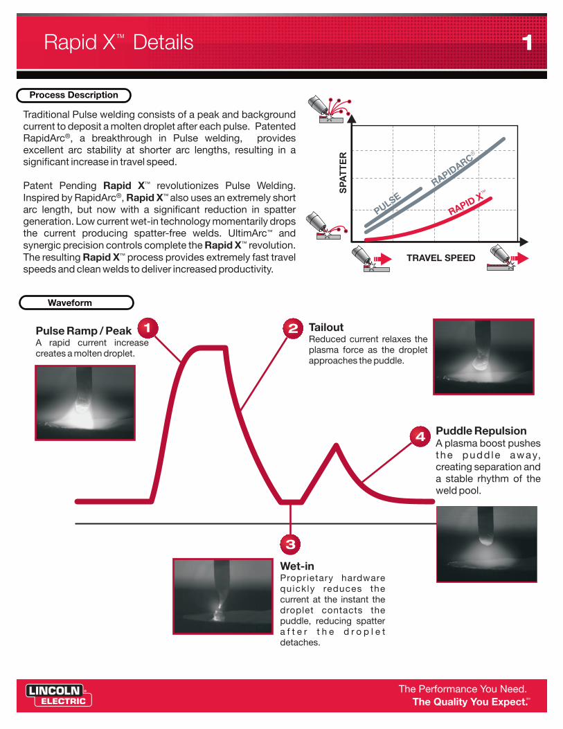
Pulse Ramp / Peak A rapid current increase creates a molten droplet.
Tailout Reduced current relaxes the plasma force as the droplet approaches the puddle.
Puddle RepulsionA plasma boost pushes the pudd le away, creating separation and a stable rhythm of the weld pool.
Wet-inProprietary hardware quickly reduces the current at the instant the droplet contacts the puddle, reducing spatter a f t e r t h e d r o p l e t detaches.
Process Description
Traditional Pulse welding consists of a peak and background current to deposit a molten droplet after each pulse. RapidArc®, a breakthrough in Pulse welding, provides excellent arc stability at shorter arc lengths, resulting in a significant increase in travel speed.
Inspired by RapidArc®, Rapid X™ utilizes an extremely short arc length. Low current wet-in technology momentarily drops the current producing spatter-free welds. UltimArc™ and synergic precision controls complete the Rapid X™ evolution. The resulting Rapid X™ process provides extremely fast travel speed and clean welds to deliver increased productivity.
Rapid X™ revolutionizes Pulse Welding.
Traditional Pulse welding consists of a peak and background current to deposit a molten droplet after each pulse. Patented
®RapidArc , a breakthrough in Pulse welding, provides excellent arc stability at shorter arc lengths, resulting in a significant increase in travel speed.
®Inspired by RapidArc ,
Low current wet-in technology momentarily drops ™the current producing spatter-free welds. UltimArc and
™synergic precision controls complete the Rapid X revolution. ™The resulting Rapid X process provides extremely fast travel
speeds and clean welds to deliver increased productivity.
™Patent Pending Rapid X revolutionizes Pulse Welding. ™Rapid X also uses an extremely short
arc length, but now with a significant reduction in spatter generation.
PULSE
®
RAPIDARC
™
RAPID X
SP
AT
TE
R
SPATTER
TRAVEL SPEED
TR
AV
EL
SP
EE
D
SPATTER
TR
AV
EL
SP
EE
D
ESLUP
™X DIPAR
Rapid X DetailsTM 1
10
2
3
4
5
6
7
Wire
Weld Joint Weld Bead
Torch Nozzle
Gas Cone
Acceptable Unacceptable
Weave
Control Knob
12:00
Weld Location
Tacking
Strike Arcon side wall
Begin welding across root
Weld across root opening
Weld in root opening
Stop arcon side wall.
Torch perpendicular to weld surface
oTorch at 45
to weld surface
oTorch at 10
to weld surface
o10
o10
o45
o45
Pipe end angle
Heat Note Material Electrode
Position
Gas
Root Opening Peak (A) Background (A) Tailout
A A
Wire Feed Speed
Synergic Welding
UltimArc Control™
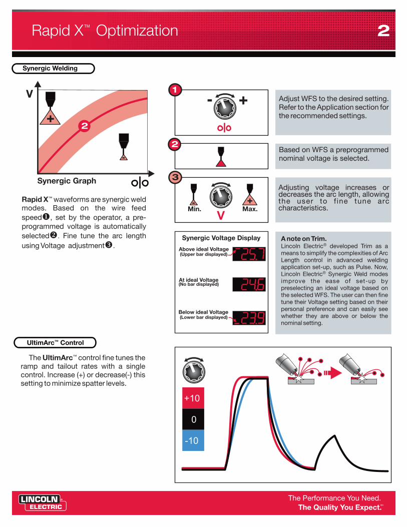
™Rapid X waveforms are synergic weld modes. Based on the wire feed speedu, set by the operator, a pre-programmed voltage is automatically selectedv. Fine tune the arc length using Voltage adjustmentw.
V
2
+10
-10
0
™ The UltimArc control fine tunes the ramp and tailout rates with a single control. Increase (+) or decrease(-) this setting to minimize spatter levels.
Synergic GraphAdjusting voltage increases or decreases the arc length, allowing the user to f ine tune arc characteristics.
V
3
Max.+
Min.-
-
+
Adjust WFS to the desired setting. Refer to the Application section for the recommended settings.
1
+-
2Based on WFS a preprogrammed nominal voltage is selected.
A note on Trim. Lincoln Electric developed Trim as a means to simplify the complexities of Arc Length control in advanced welding application set-up, such as Pulse. Now,
®Lincoln Electric Synergic Weld modes improve the ease of set-up by preselecting an ideal voltage based on the selected WFS. The user can then fine tune their Voltage setting based on their personal preference and can easily see whether they are above or below the nominal setting.
®Above ideal Voltage
At ideal Voltage
Below ideal Voltage
(Upper bar displayed)
(No bar displayed)
(Lower bar displayed)
Synergic Voltage Display
Rapid X OptimizationTM 2

10
2
3
4
5
6
7
Wire
Weld Joint Weld Bead
Torch Nozzle
Gas Cone
Acceptable Unacceptable
Weave
Control Knob
12:00
Weld Location
Tacking
Strike Arcon side wall
Begin welding across root
Weld across root opening
Weld in root opening
Stop arcon side wall.
Torch perpendicular to weld surface
oTorch at 45
to weld surface
oTorch at 10
to weld surface
o10
o10
o45
o45
Pipe end angle
Heat Note Material Electrode
Position
Gas
Root Opening Peak (A) Background (A) Tailout
A A
Wire Feed Speed
1F / PA Lap
FRONT SIDE
SIDESIDE
V
V
A
A
®SuperArc L-560.035”
®SuperArc L-560.045”
19 mm
mm m/min cm/min
Metric
�
�
�
�
oUse a 10-20 push angle. oUse a 35 work angle.
Position the electrode approximately one electrode diameter outside the joint favoring the bottom leg.
For 14ga applications position the electrode directly in the joint or slightly favoring the top edge. May require decreased work angle.
90Ar / 10CO2
80Ar / 20CO2
3/4 in.
1F
14 ga
1/4 in3/16 in.10ga12ga14ga
800800750700625
3040506065
25.024.524.024.022.0
in/min in/min260260245235220
1/4 in.3/16 in.10ga12ga14ga
500460450400375
3545505560
24.023.522.021.020.0
300280260240235
18.417.115.214.012.0
90100115125140
24.524.023.523.022.8
6.44.83.42.61.9
265245235225200
12.711.410.89.58.9
76101127140152
25.524.522.521.520.5
6.44.83.42.61.9
290270255235230
®SupraMig 1.2mm
®SupraMig 1.0mm
o o10 - 20
o35
See Customer Assistance Policy and Disclaimer Notice on page 9.
Adjust Names
Brief rundown of the changes.....
- These changes should be made in the level 2, and 3.- For all Imperial CTWD's change to 3/4". All metric to 19mm- The 1.0mm, and .035 procedures have not been altered other than CTWD.- The parameters listed below should replace the existing data for 1.2mm and .045 applications.- Also, please note that the asterisk used for the macro picture should be next to the 1.2mm data, for the 2F application.
Please let me know if you require anything else, or if you have the final versions we can scan over, and hopefully call this done.
† Mill scale may require slower travel speeds and higher voltages.†† May require the electrode to be placed directly in joint.
A note on Trim. Lincoln Electric developed Trim as a means to simplify the complexities of Volts and Amps in advanced welding application set-up, such as Pulse. Now, Lincoln Electric Synergic Weld modes (see pg 2) improve the ease of set-up by preselecting a ideal voltage based on the selected WFS. The user can then fine tune their volt setting based on their personal preference.
"Lincoln Electric developed Trim as a means to simplify the complexities of Volts and Arc Length in advanced welding application set-up, such as Pulse. While Trim has been successful in accomplishing this, there is an increasing need to use standard measurable parameters, without decoding, such as WFS, Amperage and Voltage. Lincoln Electric Power Feed® wire feeders providethe user with an indication of whether their voltage is higher or lower than the nominal setting. for a particularwire feed speed"
And we could include this if we want to reinforce it is still easy and change the wording from Synergic Control CV Voltage display to Synergic Voltage Display, and of course some of the wording
Rapid X ApplicationsTM 3
10
2
3
4
5
6
7
Wire
Weld Joint Weld Bead
Torch Nozzle
Gas Cone
Acceptable Unacceptable
Weave
Control Knob
12:00
Weld Location
Tacking
Strike Arcon side wall
Begin welding across root
Weld across root opening
Weld in root opening
Stop arcon side wall.
Torch perpendicular to weld surface
oTorch at 45
to weld surface
oTorch at 10
to weld surface
o10
o10
o45
o45
Pipe end angle
Heat Note Material Electrode
Position
Gas
Root Opening Peak (A) Background (A) Tailout
A A
Wire Feed Speed
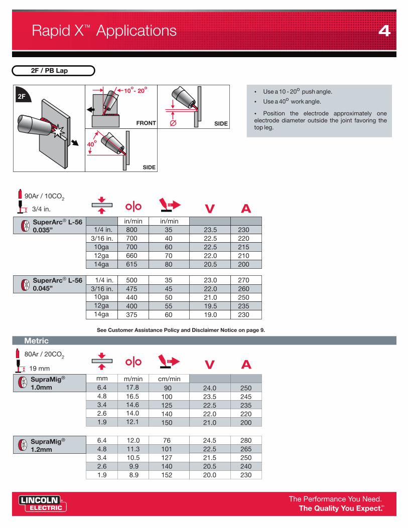
2F / PB Lap
SIDEFRONT
SIDE
1/4 in.3/16 in.10ga12ga14ga
500475440400375
3545505560
23.022.021.019.519.0
270260250235230
6.44.83.42.61.9
12.011.310.59.98.9
76101127140152
24.522.521.520.520.0
280265250240230
1/4 in.3/16 in.10ga12ga14ga
800700700660615
3540607080
23.522.522.522.020.5
230220215210200
6.44.83.42.61.9
17.816.514.614.012.1
90100125140150
24.023.522.522.021.0
250245235220200
mm
in/min
m/min
in/min
cm/min
Metric
�
�
�
oUse a 10 - 20 push angle.
oUse a 40 work angle.
Position the electrode approximately one electrode diameter outside the joint favoring the top leg.
2F
o o10 - 20
o40
90Ar / 10CO2
80Ar / 20CO2
V A
V A
See Customer Assistance Policy and Disclaimer Notice on page 9.
19 mm
3/4 in.
®SuperArc L-560.035”
®SuperArc L-560.045”
®SupraMig 1.2mm
®SupraMig 1.0mm
Rapid X ApplicationsTM 4

10
2
3
4
5
6
7
Wire
Weld Joint Weld Bead
Torch Nozzle
Gas Cone
Acceptable Unacceptable
Weave
Control Knob
12:00
Weld Location
Tacking
Strike Arcon side wall
Begin welding across root
Weld across root opening
Weld in root opening
Stop arcon side wall.
Torch perpendicular to weld surface
oTorch at 45
to weld surface
oTorch at 10
to weld surface
o10
o10
o45
o45
Pipe end angle
Heat Note Material Electrode
Position
Gas
Root Opening Peak (A) Background (A) Tailout
A A
Wire Feed Speed
o10
o30
14 ga
3F
TOP TOP
TOPSIDE
3F / PG Lap
3/16 in.10ga12ga14ga
475400400360
50506070
22.021.021.019.5
295260260240
4.83.42.61.9
11.49.79.78.9
127127152178
23.021.521.520.5
280250250230
3/16 in.10ga12ga14ga
780650650600
50506070
24.023.022.522.0
260235235230
4.83.42.61.9
15.915.214.012.1
125140152165
24.024.023.322.5
240225220210
mm
in/min
m/min
in/min
cm/min
Metric
�
�
�
�
o Use a 10 drag angle.
o Use a 30 work angle.
Position the electrode approximately one electrode diameter outside the joint favoring the bottom leg.
For 14ga applications position the electrode directly in the joint or slightly favoring the edge.
V A
V A
See Customer Assistance Policy and Disclaimer Notice on page 9.
19 mm
3/4 in.
90Ar / 10CO2
80Ar / 20CO2
®SuperArc L-560.035”
®SuperArc L-560.045”
®SupraMig 1.2mm
®SupraMig 1.0mm
A note on Trim. Lincoln Electric developed Trim as a means to simplify the complexities of Volts and Amps in welding application set-up. While Trim has been successful, our company recognizes and responds to the needs of a global market. An increasing demand for global ly measurable parameters, without decoding, has lead Lincoln Electric to focus on universal terms: WFS, Amperage and Voltage.
V Min.
Max.
2
Rapid X ApplicationsTM 5

10
2
3
4
5
6
7
Wire
Weld Joint Weld Bead
Torch Nozzle
Gas Cone
Acceptable Unacceptable
Weave
Control Knob
12:00
Weld Location
Tacking
Strike Arcon side wall
Begin welding across root
Weld across root opening
Weld in root opening
Stop arcon side wall.
Torch perpendicular to weld surface
oTorch at 45
to weld surface
oTorch at 10
to weld surface
o10
o10
o45
o45
Pipe end angle
Heat Note Material Electrode
Position
Gas
Root Opening Peak (A) Background (A) Tailout
A A
Wire Feed Speed
+ A negative sense lead is optional to monitor arc voltage, however it is highly recommended for total welding cable lengths in excess of 50 ft. The sense lead should be connected directly to the workpiece.
A negative sense lead (optional) is highly recommended for total welding cable lengths >50 ft. and should be connected directly to the workpiece.
A positive (+) sense lead is required. This ®is a standard connection in an Arclink
cable.
For best performance, connect the work sense lead close to the welding arc.
The negative sense lead should be separated away from welding cables to minimize interference.
DO NOT route sense lead cable close to high current welding cables as this may distort the sense lead signal.
DO NOT route sense lead cable close to high current welding cables as this may distort the sense lead signal.
DO NOT connect either sense lead to a welding stud as this may result in erratic arc or increased spatter.
+
- -C
A
B
If A+B+C > 50 ft (15 meters) use coaxial welding cables. They combine the positive and negative welding leads into one cable.
For configurations with excessive ®inductance, use Lincoln Electric
patented coaxial welding cables.
® Lincoln Electric coaxial cables combine the positive and negative welding leads into one cable to minimize cable inductance.
Test cable inductance levels using the ®Power Wave Manager software
®exclusively from Lincoln Electric .
Connect the work lead to the negative stud on the power source and directly to the work piece. Maintain the shortest connection length possible.
The total length of the welding current loop (A+B+C) should be minimized to reduce inductance.
Route cables (A,B) close together to further reduce cable inductance.
Sense Leads
Work Leads
+
+
--
-
--
67 (+) sense lead
21 (-) sense lead
Work Clamp
Work Clamp
Rapid X Set-UpTM 6

Connection Diagram
10
2
3
4
5
6
7
Wire
Weld Joint Weld Bead
Torch Nozzle
Gas Cone
Acceptable Unacceptable
Weave
Control Knob
12:00
Weld Location
Tacking
Strike Arcon side wall
Begin welding across root
Weld across root opening
Weld in root opening
Stop arcon side wall.
Torch perpendicular to weld surface
oTorch at 45
to weld surface
oTorch at 10
to weld surface
o10
o10
o45
o45
Pipe end angle
Heat Note Material Electrode
Position
Gas
Root Opening Peak (A) Background (A) Tailout
A A
Wire Feed Speed+
-
W
Rapid X Set-UpTM 7

!
!
Troubleshooting
Spatter
VVolts
Erratic Arc
Travel Speed
Push Angle
Porosity Poor PenetrationUnder Cut Convex Bead Burn Through
Wire Feed Speed
Contact Tipto Work Distance
o?
Tip
Sense Lead
?Gas Coverage
Surface Contaminates
Proper Feeding
+
10
2
3
4
5
6
7
Wire
Weld Joint Weld Bead
Torch Nozzle
Gas Cone
Acceptable Unacceptable
Weave
Control Knob
12:00
Weld Location
Tacking
Strike Arcon side wall
Begin welding across root
Weld across root opening
Weld in root opening
Stop arcon side wall.
Torch perpendicular to weld surface
oTorch at 45
to weld surface
oTorch at 10
to weld surface
o10
o10
o45
o45
Pipe end angle
Heat Note Material Electrode
Position
Gas
Root Opening Peak (A) Background (A) Tailout
A A
Wire Feed Speed
+
+ +
+
++ +
+ +
+
+
+
+
-
- -
- -
- -
- -
- -
- - -
-
-
-
-
--
--
-
Increase Decrease Inspect & Replace !
!
!
!
! !!
!!
!
!
!
!!
!
Important
Concave Bead
Problem
So
luti
on
Rapid X Set-UpTM 8
10
2
3
4
5
6
7
Wire
Weld Joint Weld Bead
Torch Nozzle
Gas Cone
Acceptable Unacceptable
Weave
Control Knob
12:00
Weld Location
Tacking
Strike Arcon side wall
Begin welding across root
Weld across root opening
Weld in root opening
Stop arcon side wall.
Torch perpendicular to weld surface
oTorch at 45
to weld surface
oTorch at 10
to weld surface
o10
o10
o45
o45
Pipe end angle
Heat Note Material Electrode
Position
Gas
Root Opening Peak (A) Background (A) Tailout
A A
Wire Feed Speed
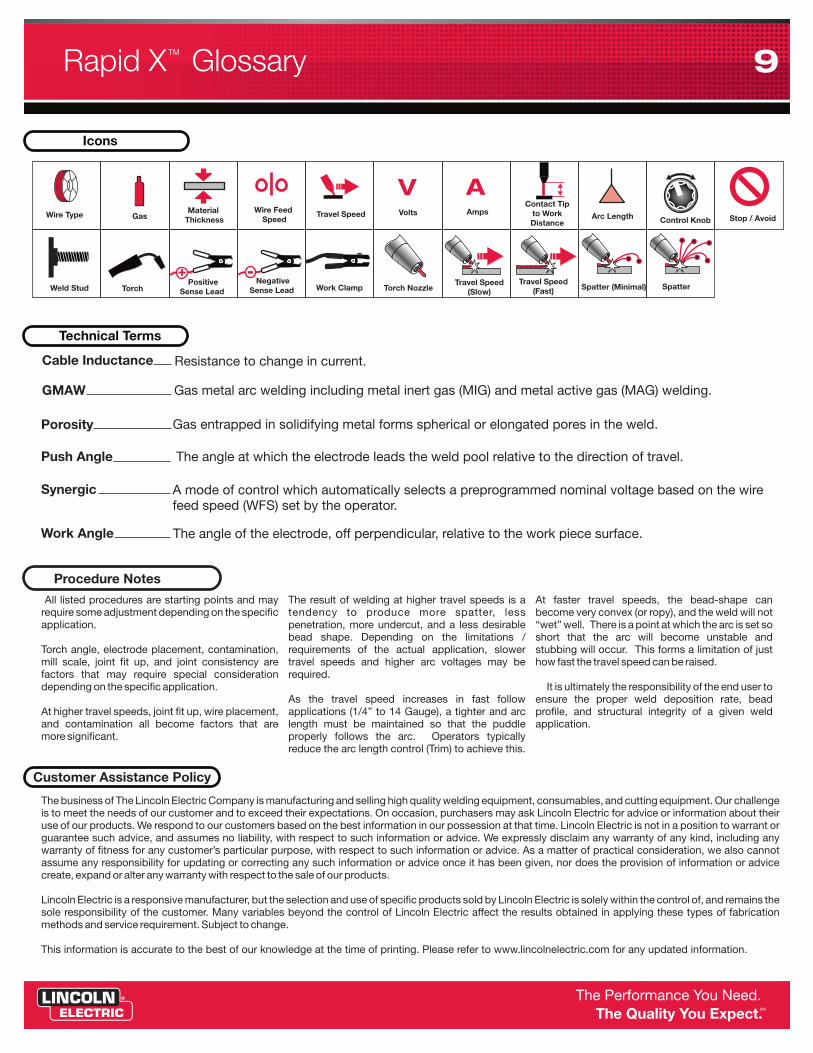
Icons
Technical Terms
Control Knob
Weld Stud Torch NozzleWork ClampTorchTravel Speed
(Slow)Travel Speed
(Fast)
V ATravel SpeedWire Feed
SpeedMaterial
ThicknessGasWire Type VoltsContact Tip
to Work Distance
Amps
SpatterSpatter (Minimal)
Arc Length Stop / Avoid
Cable Inductance
GMAW
Porosity
Push Angle
Synergic
Work Angle
Resistance to change in current.
Gas metal arc welding including metal inert gas (MIG) and metal active gas (MAG) welding.
Gas entrapped in solidifying metal forms spherical or elongated pores in the weld.
The angle at which the electrode leads the weld pool relative to the direction of travel.
A mode of control which automatically selects a preprogrammed nominal voltage based on the wire feed speed (WFS) set by the operator.
The angle of the electrode, off perpendicular, relative to the work piece surface.
The business of The Lincoln Electric Company is manufacturing and selling high quality welding equipment, consumables, and cutting equipment. Our challenge is to meet the needs of our customer and to exceed their expectations. On occasion, purchasers may ask Lincoln Electric for advice or information about their use of our products. We respond to our customers based on the best information in our possession at that time. Lincoln Electric is not in a position to warrant or guarantee such advice, and assumes no liability, with respect to such information or advice. We expressly disclaim any warranty of any kind, including any warranty of fitness for any customer’s particular purpose, with respect to such information or advice. As a matter of practical consideration, we also cannot assume any responsibility for updating or correcting any such information or advice once it has been given, nor does the provision of information or advice create, expand or alter any warranty with respect to the sale of our products.
Lincoln Electric is a responsive manufacturer, but the selection and use of specific products sold by Lincoln Electric is solely within the control of, and remains the sole responsibility of the customer. Many variables beyond the control of Lincoln Electric affect the results obtained in applying these types of fabrication methods and service requirement. Subject to change.
This information is accurate to the best of our knowledge at the time of printing. Please refer to www.lincolnelectric.com for any updated information.
Customer Assistance Policy
Procedure Notes
All listed procedures are starting points and may The result of welding at higher travel speeds is a At faster travel speeds, the bead-shape can require some adjustment depending on the specific tendency to produce more spatter, less become very convex (or ropy), and the weld will not application. penetration, more undercut, and a less desirable “wet” well. There is a point at which the arc is set so
bead shape. Depending on the limitations / short that the arc will become unstable and Torch angle, electrode placement, contamination, requirements of the actual application, slower stubbing will occur. This forms a limitation of just mill scale, joint fit up, and joint consistency are travel speeds and higher arc voltages may be how fast the travel speed can be raised. factors that may require special consideration required. depending on the specific application. It is ultimately the responsibility of the end user to
As the travel speed increases in fast follow ensure the proper weld deposition rate, bead At higher travel speeds, joint fit up, wire placement, applications (1/4” to 14 Gauge), a tighter and arc profile, and structural integrity of a given weld and contamination all become factors that are length must be maintained so that the puddle application.more significant. properly follows the arc. Operators typically
reduce the arc length control (Trim) to achieve this.
Negative Sense Lead
- Positive
Sense Lead
+
As Lincoln works to meet the needs of a global market it becomes necessary to speak a global language in regards to welding parameters. WFS, Amperage, and Voltage have always been measurable, universal terms related to welding parameters. Defining procedures by these terms allows customers to transfer information globally without having to decode parameter settings or train personal on the meaning of specific terms. Since the meaning of "Trim" changes from process to process, and from power source to power source it makes it difficult to communicate necessary process information effectively on a global level.
Lincoln Electric developed Trim as a means to simplify the complexities of Volts and Amps in welding application set-up. While Trim has been successful, our company recognizes and responds to the needs of a global market. An increasing demand for globally measurable parameters, without decoding, has lead Lincoln Electric to focus on universal terms: WFS, Amperage and Voltage.
Rapid X GlossaryTM 9