Embed Size (px)
Citation preview
Plasmonic Force Propulsion Revolutionizes Nano/PicoSat Propulsion
Joshua L. Rovey and Xiaodong Yang
Department of Mechanical and Aerospace Engineering
1
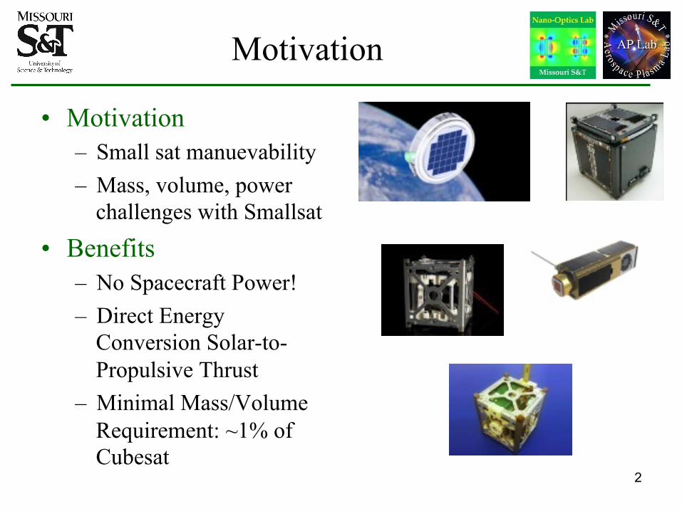
Motivation
• Motivation – Small sat manuevability
Mass, volume, power challenges with Smallsat
–
– Benefits
No Spacecraft Power! Direct Energy Conversion Solar-to-Propulsive Thrust Minimal Mass/Volume Requirement: ~1% of Cubesat
–
–
2
•
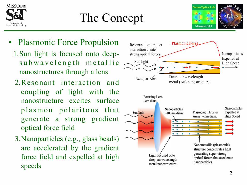
The Concept
• Plasmonic Force Propulsion 1. Sun light is focused onto deep-
s u b w a v e l e n g t h m e t a l l i c nanostructures through a lens
2. Resonant interact ion and coupling of light with the nanostructure excites surface p l a s m o n p o l a r i t o n s t h a t generate a strong gradient optical force field
3. Nanoparticles (e.g., glass beads) are accelerated by the gradient force field and expelled at high speeds
3
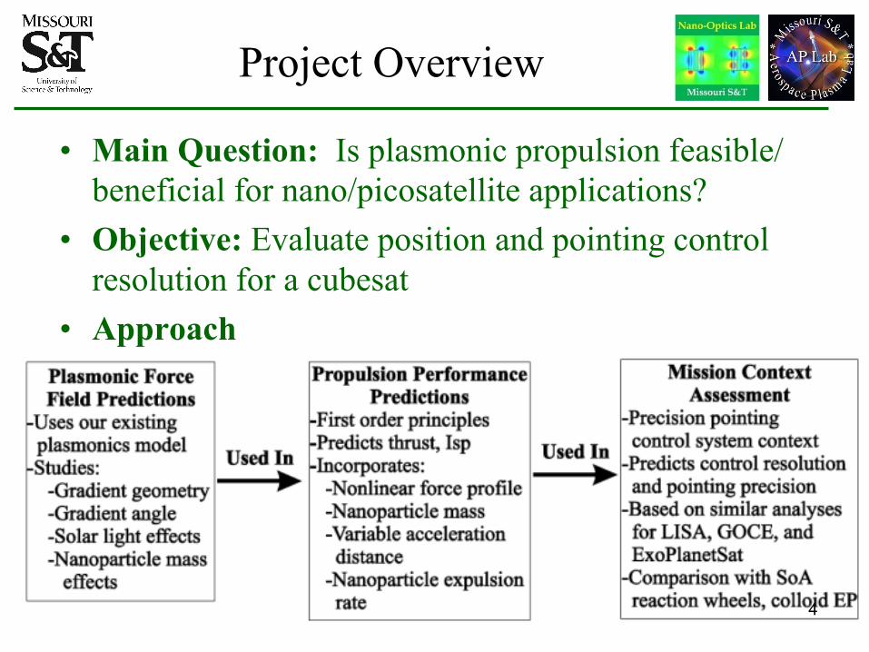
Project Overview
•
•
•
Main Question: Is plasmonic propulsion feasible/ beneficial for nano/picosatellite applications? Objective: Evaluate position and pointing control resolution for a cubesat Approach
4
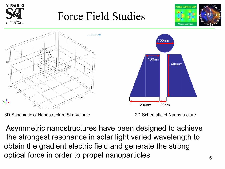
Force Field Studies
3D-Schematic of Nanostructure Sim Volume
400nm 100nm
100nm
200nm 30nm
2D-Schematic of Nanostructure
Asymmetric nanostructures have been designed to achieve the strongest resonance in solar light varied wavelength to obtain the gradient electric field and generate the strong optical force in order to propel nanoparticles 5
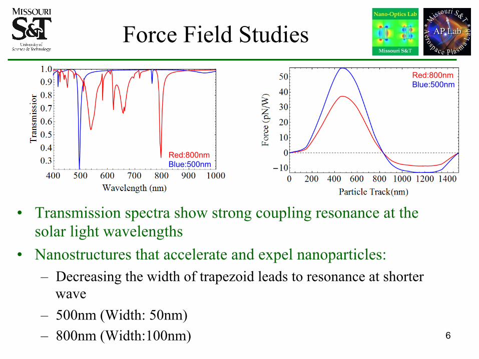
Force Field Studies
•
•
Transmission spectra show strong coupling resonance at the solar light wavelengths Nanostructures that accelerate and expel nanoparticles: –
– –
Decreasing the width of trapezoid leads to resonance at shorter wave 500nm (Width: 50nm) 800nm (Width:100nm) 6
Red:800nm Blue:500nm
Red:800nm Blue:500nm
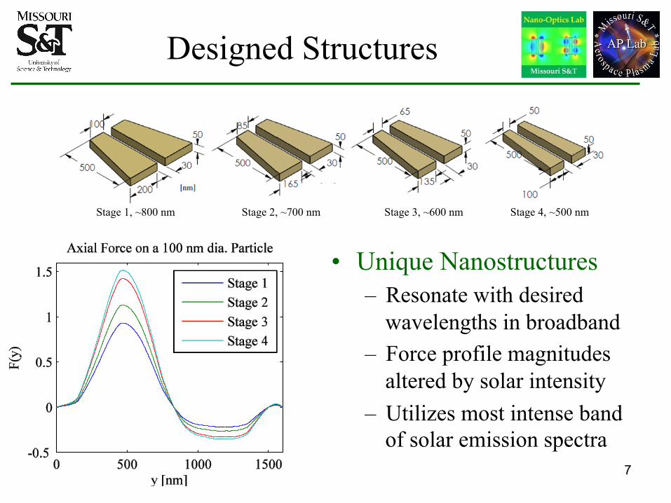
Designed Structures
Stage 1, ~800 nm Stage 2, ~700 nm Stage 3, ~600 nm Stage 4, ~500 nm
• Unique Nanostructures –
–
–
Resonate with desired wavelengths in broadband Force profile magnitudes altered by solar intensity Utilizes most intense band of solar emission spectra
7
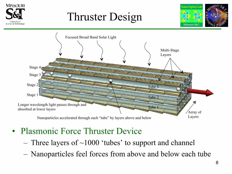
Thruster Design
•
Focused Broad Band Solar Light
Stage 4
Stage 3
Stage 2
Stage 1
Longer wavelength light passes through and absorbed at lower layers
Tube 3
Tube 2
Tube 1 Array of Layers Nanoparticles accelerated through each “tube” by layers above and below
Multi-Stage Layers
Plasmonic Force Thruster Device – –Three layers of ~1000 ‘tubes’ to support and channel Nanoparticles feel forces from above and below each tube
8
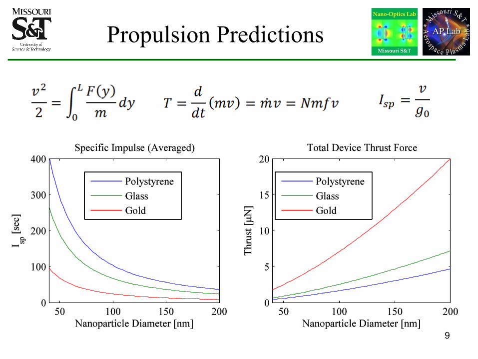
Propulsion Predictions
9
Mission Context Assessment
•
•
On-Off ACS Model – –
–
Simple First-Principles Analysis Quickly Compare SoA Thrusters/Torquers Control Authority Pointing and Positioning Accuracy
Cubesat RCSs compared using following assumptions –
–––
Attitude constantly known with zero error Minimum impulse bit for each thruster has no variation. Solar radiation pressure is only disturbance Solid 1U cube sat with 2 kg mass
10
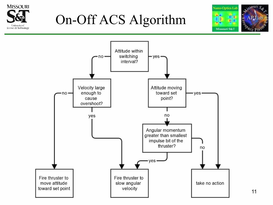
On-Off ACS Algorithm
11
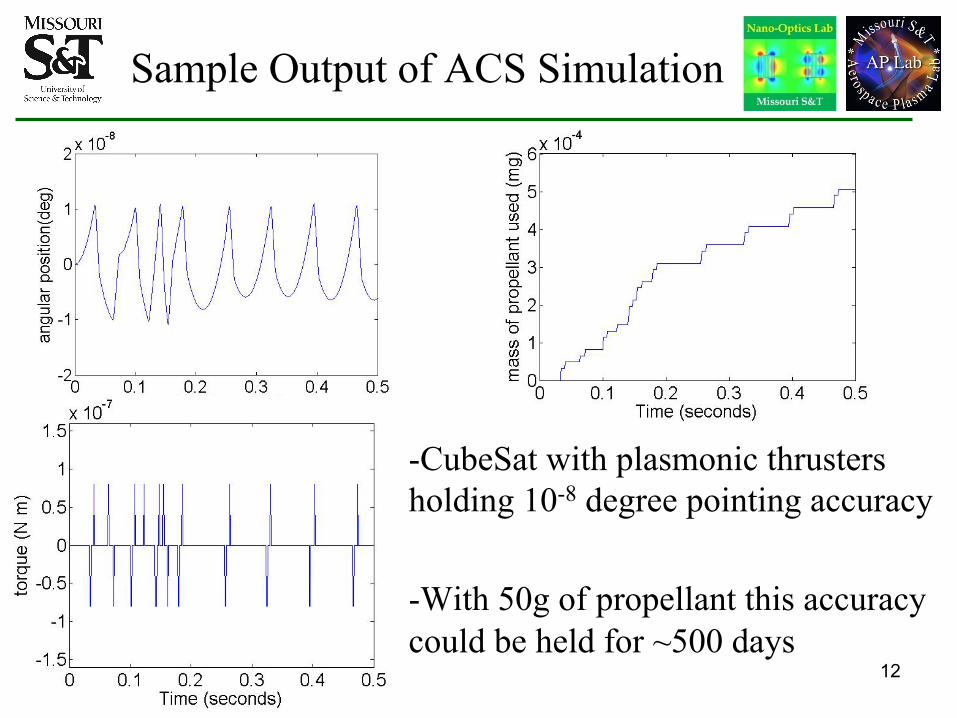
Sample Output of ACS Simulation
-CubeSat with plasmonic thrusters holding 10-8 degree pointing accuracy -With 50g of propellant this accuracy could be held for ~500 days
12
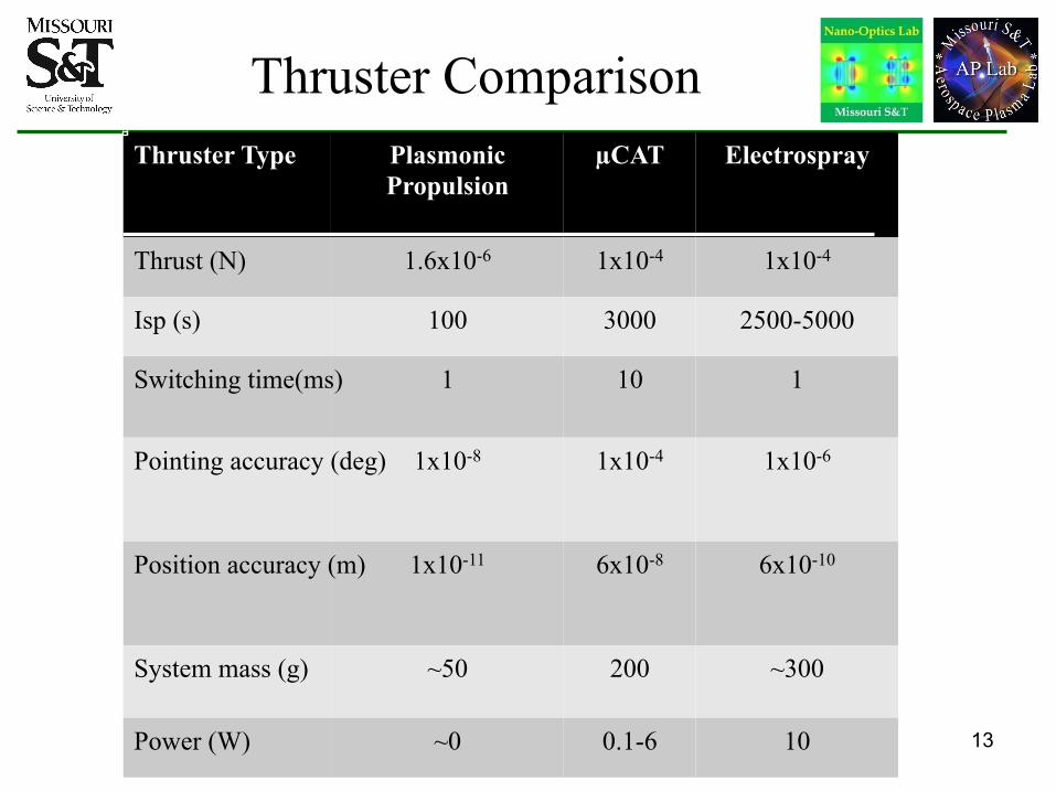
Thruster Comparison Thruster Type Plasmonic
Propulsion µCAT Electrospray
Thrust (N) 1.6x10⁻⁶ 1x10⁻⁴ 1x10⁻⁴
Isp (s) 100 3000 2500-5000
Switching time(ms) 1 10 1
Pointing accuracy (deg) 1x10⁻⁸ 1x10⁻⁴ 1x10⁻⁶
Position accuracy (m) 1x10-11 6x10⁻⁸ 6x10⁻¹⁰
System mass (g) ~50 200 ~300
Power (W) ~0 0.1-6 10 13
Other Activities
• NASA Interaction –– Ames: Lead for Small Spacecraft Mission Design Division
• • •
•
Division Chief: Dr. Chad Frost Chief Technologist: Dr. Elwood Agasid Conduct early-stage concept development and technology maturation supporting the Center's space mission proposals Facilities and software for rapid mission development and analysis. Experts covering the domains required to fully develop successful spacecraft mission concepts
14
Phase II Plans
• •
Raise TRL 2 to 3 Experimentally Demonstrate Nanoparticle Propulsion –
–
– –
Fabricate single, multi-stage asymmetric nanostructures Characterize transmission spectra, characterize nanoparticle motion Compare experiment with model predictions Update propulsion predictions, Smallsat controllability predictions
15
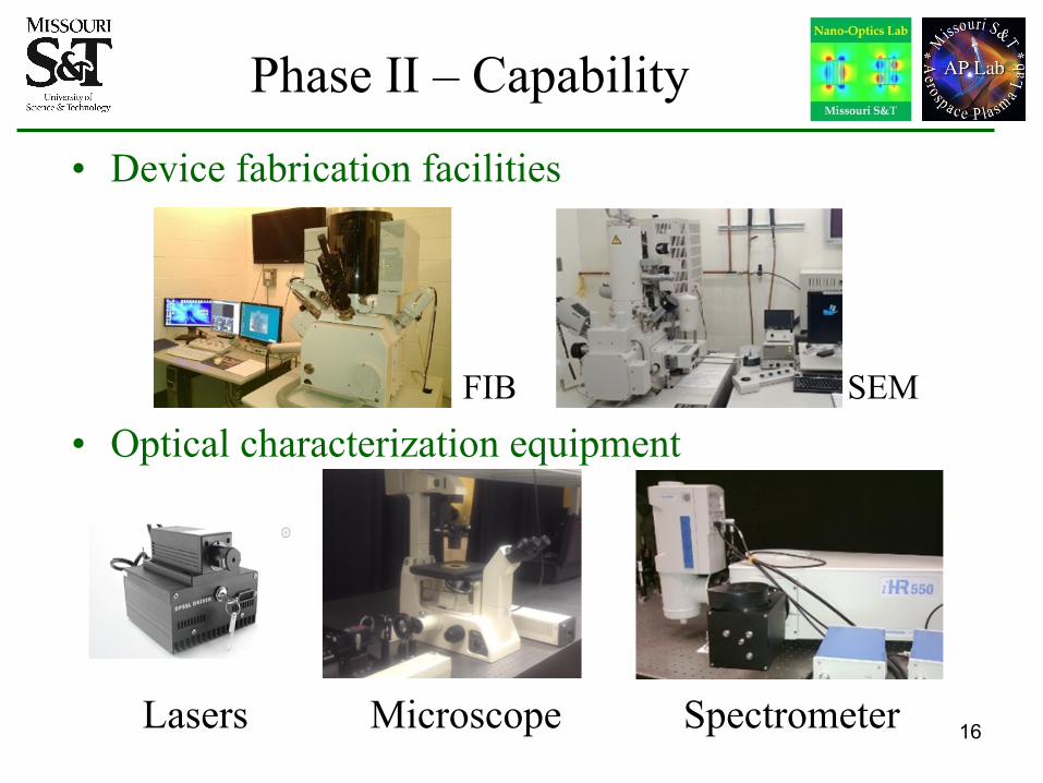
Phase II – Capability
• Device fabrication facilities
FIB SEM
• Optical characterization equipment
Lasers Microscope Spectrometer 16
Major Conclusions to Date
• Main Question: Is plasmonic propulsion feasible for nano/picosatellite applications? – Still to be finalized, but appears promising
•
•
• •
Nanostructures that produce fields for expelling nanostructures are possible – Can also be designed with narrow band in solar spectrum,
i.e., 40nm FWHM for 500nm resonance Optimum Use of Solar Light and Useable Thrust Requires Multi-stage, Layered, Arrays NASA Ames wants to work with us Phase II – we have the capability to Raise TRL 2 to 3 – Facilities, equipment to fabricate, test nanostructures 17
Questions?
18