Embed Size (px)
Citation preview

Quality Audit report
of
Carriage Workshop
Ajmer, NW Rly
Report no. 68/2012
MAY 2012
( Audit is done by CMPE/DMU/HQ, NR )
Co-ordinated by
Quality Assurance ( Mechanical) Directorate
Research Designs & Standards Organisation Manak Nagar, Lucknow - 226011

Page 1 of 31 Carriage Workshop – AII, NW Rly May 2012
Quality audit Report of Ajmer Workshop, NW Railway
1.0 Introduction
Quality audit of the repair and maintenance practices followed at Ajmer Workshop was carried out as per Railway Board’s letter no. 2012/M(W)/814/5 dt. 20.03.2012 and RDSO letter no. QAM/Quality Audit Dt. 21.03.2012.
1.1 Audit Team – Sh. Amitabh, CPM/J&K and CMPE/DMU/HQ, Sh. Vikas Anand, Dy. CME/JUDW, Sh. Anup Singh, SSE/JUDW, Sh. Rajesh Dhatwalia, SSE/JUDW, Sh. A Raja SSE/JUDW, Sh. Rakesh Gera SSE/JUDW, Sh. R U Khan SSE/AMV-LKO, Sh. Birbal Singh SSE/AMV-LKO, Sh. Sanjeev Sharma IOR/UMB Division, Sh Kulbhushan SSE/FZR, Sh. Karun Kapil SSE/NDBH, Sh. Devendra Pingolia, SSE/IT
1.2 Date(s) of Audit – 26.04.2012 & 27.04.2012 1.3 Escorting officials – Sh. Sudhir Gupta, CWM/AII, Sh. A K Abrol, Dy. CME/
Carr/AII, Sh. Ram Pratap, PE/Carr/AII, Sh. R N Choudhary, WM/Carr/AII, Sh. S K Srivastava, CMT/Carr/AII, Sh. R A Yadav, AWM/Carr/AII, Sh. Vishnu Seth, SSE/Carr/AII, Sh. Harsh Vardhan, SSE/Carr/AII, Sh. Jai Singh, SSE/Carr/AII, Sh. R S Chaturvedi, SSE/Carr/AII, Sh. Dayal Harisinghani, SSE/Carr/AII, Sh. Dhan Singh, SSE/Carr/AII, Sh. Meghraj Parihar, SSE/Carr/AII, Sh. Vishnu Prakash, SSE/Carr/AII
1.4 Scope of Audit – Wheel & Roller Bearing shop, Bogie Repair shop, Brake block
hanger maintenance, Air Brake shop and Interior furnishing.
2.0 Brief about Workshop Central Workshop (Loco, Carriage & Wagon) built in 1877. Carriage and Wagon Workshop was built in 1884 for repairs and manufacture of Carriage and Wagon for the Rajputanamalwa Railway. POH of first BG AC Coach in C&W Workshop was started on 29.03.96. Steel casting produced in this shop in 1902. Certified ISO 9002:1994 in 2001. Re-certified ISO 9001:2000 in 2007. Modernization plan sanctioned in 2007-08. Certified ISO 9001:2008 in August 2010. It is currently carring out POH of 109 BG coaches (82 Non - AC POH + 07 Non – AC Refurbishing and 18 AC POH + 02 AC refurbishing) per month. This workshop also carries out POH of POW and RROW.

Page 2 of 31 Carriage Workshop – AII, NW Rly May 2012
3.0 Strengths
3..1 ‘A’ Schedule Painting: About 10 coaches per month are attended which includes all the refurbished coaches. Quality of painting is satisfactory since old layers of paint are effectively removed.
4.0 Weaknesses
4.1 Roller Bearing, Wheel & Axle Section 4.1.1 Digital micrometer is not being used for checking the dimension of axle. The
micrometer in use may result in giving incorrect reading.
4.1.2 Suitable instructions for measurement of surface finish are not available.
4.1.3 Surface finish on the wheel seat is not measured and recorded though same has been prescribed as 1.6 micron.
4.1.4 Cleaning of axle boxes is done with the solvent spray in open. Spray jet machine was giving fumes which are causing unpleasant environment.
4.1.5 Thread plug gauge is not used for checking the thread in roller bearing section and bolts are directly fitted and tightened.
4.1.6 Spray jet cleaning of axle box is not being done in the floor chamber. However, the same is done in the open surrounding.
4.1.7 Induction heater with demagnetize device is not available. 4.2 Bogie Section 4.2.1 Bogie frames are cleaned by scrapping. High pressure hot water jet is not being
used for removing all the dirt and dust.
4.2.2 Manipulators are not available for ensuring down hand welding. Before any repair of bogies, the bogie frames are not cleaned to bare metal as there is no provision of sand blasting.
4.2.3 Brake beam ends are being replaced if found unserviceable. However, proper fixtures need to be used for checking the squareness.
4.2.4 All brake gear components required to be given two coats of red oxide primer and 4 coats of bituminous solution and one coat of anti corrosive lead paint. However, only single coat of red oxide and bituminous solution is given to few components of brake gear.
4.2.5 The machine for checking the assembled bogie for load testing is defective and was not working.

Page 3 of 31 Carriage Workshop – AII, NW Rly May 2012
4.3 Brake Block Hanger Brake block hanger are not checked for wear on the bore of the hole with the
help of the plug gauge. 4.4 Interior Fittings (Furnishings) For maintenance of windows of non-AC coaches the entire window assembly
should be dismantled and shutter removed. Broken or cracked glasses should be replaced with toughened glass. However, this is not being followed by the workshop.
4.4.1 Compreg sheet is not coated with water sealing compound.
4.4.2 For maintenance of upholstery 9 core of cotton threads are used instead of nylon sewing threads. Nails are being used instead of pneumatic staplers. 4.5 Air Brake System
Transportation of DV from overhauling section to the coach is not done in proper boxes to avoid damage/ingress of dirt.
4.5.1 The stacking up of air brake components required to be improved.

Page 4 of 31 Carriage Workshop – AII, NW Rly May 2012
List of Annexures
No. Subject
1 Sick Marking of Coaches with 100 days of POH
2 Sick Marking of Coaches in Coaching Depots of JP and AII Divn. During Primary Maintenance
3 Roller bearing, Wheels & Axles (ICF Wheels)
4 BOGIE OVERHAUL
5 Maintenance for Brake Block Hanger for ICF coaches
6 Interior fittings (Furnishings)
7 air brake system

Page 5 of 31 Carriage Workshop – AII, NW Rly May 2012
Annexure 1
Sick marking of coaches within 100 days of POH (BG) Year 2011-12 (All Rly.)
Sr. No
Defect
Ap
r.1
1
Ma
y.1
1
Ju
ne.1
1
Ju
ly.1
1
Au
g.1
1
Se
pt.
1
1
Oc
t.11
No
v.1
1
Dec
.11
Ja
n.1
2
Feb
.12
Ma
r.1
2
To
tal
1 Wheel defects - - 1 1
2 Roller bearing defects - 1 1 2
3 Bolster spring. Broken/weak
- - 1 1 1 3
4 Axle box spring. Broken/weak
- -
5 Equalizing Stay rod spring. Broken/weak
- -
6 Anchor link bent/broken
- -
7 Bolster assembly defect
- -
8 Centre pivot defect - -
9 Shock absorber defective
- -
10 Vacuum cylinder defect
-
11 Vacuum train pipe leakage
-
12 D.V. defective 2 2 1 1 6
13 Air brake cylinder def. - - 1 1
14 BP/EP def. - -
15 ACP apparatus def. - -
16 Head stock/diagonal crack broken/sole bar drooping
- -
17 Water tank/system leaky
- 1 1
18 Buff. Head Stock patch/broken
- -
19 Poor carpentry work - -
20 Main door def. - -
21 Buffer assembly def. - 1 1 1 3
22 Other defects 1 - 2 1 1 1 1 7
Total(Mechanical) 3 5 1 2 0 2 1 1 2 2 3 2 24
Total (Elect.) 6 1 6 6 7 4 2 3 2 4 3 3 47
Grand total 9 6 7 8 7 6 3 4 4 6 6 5 71

Page 6 of 31 Carriage Workshop – AII, NW Rly May 2012
Sick marking of coaches within 100 days of POH (BG) Year Comparative From
2009-10 to 2011-12
S No
Defect 2009-10 2010-11 2011-12
1 Wheel defects 01 01 1
2 Roller bearing defects 03 0 2
3 Bolster spring. Broken/weak 05 03 3
4 Axle box spring. Broken/weak 01 1 0
5 Equalizing Stay rod spring. Broken/weak
- 0 0
6 Anchor link bent/broken - 0 0
7 Bolster assembly defect 01 0 0
8 Centre pivot defect - 01 0
9 Shock absorber defective - 01 0
10 Vacuum cylinder defect - 0 0
11 Vacuum train pipe leakage - 0 0
12 D.V. defective 05 06 6
13 Air brake cylinder def. 02 01 1
14 BP/EP def. 06 0 0
15 ACP apparatus def. - 0 0
16 Head stock/diagonal crack broken/sole bar drooping
- 0 0
17 Water tank/system leaky 04 04 1
18 Buff. Head Stock patch/broken 01 0 0
19 Poor carpentry work - 0 0
20 Main door def. 03 0 0
21 Buffer assembly def. 01 0 3
22 Other defects 19 17 7
Total(Mechanical) 52 35 24
Total (Elect.) 53 24 47
Grand total 105 59 71

Page 7 of 31 Carriage Workshop – AII, NW Rly May 2012
Annexure 2
Sick Marking during Primary Maintenance of Coaches in Jaipur division
Defect 2009-10 2010-11 2011-12
Axle box spring 0 1 0
Bolster spring 0 2 2
Buffer 32 97 72
Deshpot 59 24 15
Furnishing/Upholistry 5 0 0
V- belt 142 184 130
Wheel 166 211 196
Other 115 114 103
Total 519 633 518
Holding of Jaipur division
AC Non Ac
108 428
Sick Marking during Primary Maintenance of Coaches in Ajmer division
Defect 2009-10 2010-11 2011-12
Axle box spring 0 5 1
Bolster spring 6 15 1
Buffer 0 3 3
Deshpot 9 18 6
Furnishing/Upholistry 17 42 7
V- belt 46 51 36
Wheel 5 6 6
Other 21 45 25
Total 104 185 85
Holding of Aii division
AC Non Ac
108 412

Page 8 of 31 Carriage Workshop – AII, NW Rly May 2012
Annexure 3 Check Sheet for Quality Audit of
Roller bearing, Wheels & Axles (ICF Wheels) (Ref.: CAMTECH Maintenance Manual for BG coaches of ICF Design and Technical Pamphlet C-7817)
SN REQUIREMENTS CLAUSE OBSERVATIONS 1. Check that wheel gauge (1600+2/-1) is being
measured at 3 location 120º apart. 1001 c (i) (a) In pre- inspection only GO & NOT
GO gauge is being used at 03 locations. In final stage line gauge is being used and record is maintained of maximum dimension. Additionally this dimension is also being maintained on CNC machine and record is kept.
2. Check that wheel dia is being measured with the help of trammel gauge with least count of 0.5mm or wheel dia measuring gauge of least count of 0.1mm. Check that wheel flanges are being checked with the help of wheel profile gauge and thickness and height of flanges is being measured. The difference in tread dia of the two wheels on the same axle permitted is 0.5mm max and this is being measured. Check that wheels turned out from wheel shop are according to shop issue sizes.
1001 c (i) (b & d)
Being checked. Shop is using worn wheel profile to extract maximum life. Effort is to give minimum depth of cut even by reducing the flange thickness to the lower permitted values. RDSO needs to review its instruction regarding flange thickness of the last shop issue size wheel. As per the existing instructions, wheel profile to Sketch – 91146 demands flange thickness of 29 mm on the wheel diameter of last shop issue size necessitating huge depth of cut which will do away all the benefits accrued by adopting WWP. Ajmer workshop and CME/NWR have referred this matter to RDSO which should be clarified at the earliest.
ICF/BEML solid New - 915 Shop issue-836 3. Check that each axle are being thoroughly cleaned for
inspection & inspected for pitting, ovality, taper, ridges & ultrasonically as per RDSO procedure.
Taper must not exceed – 0.015/0.01mm
Out of roundness must not exceed-0.015/0.02mm
1001c (i) (e) Analogue micrometer with L.C. -0.01 is being used to measure the taper. In case of doubt, digital micrometer having LC of 0.001mm is used to verify. Shop was advised to invariably use digital micrometer for all readings.
4. Check that wheels are being categorised into following categories after pre-inspection. (i) Normal repair wheels. (ii) Wheels requiring replacement of Axle. (iii) Wheels requiring replacement of Wheel discs
1002 Being done
5 The wheel should be inspected for rejectable defects in accordance with CMI/K003. (i) All wheel sets must be cleaned with high pressure jet machine. (ii) Wheels with thermal cracks or heat checks must be subjected to ultrasonic testing of the rim prior to removal of defect by machine. (iii) A wheel disc that is bent or show signs of being loosely fitted the axle should be rejected. (iv) Wheel sets overheated due to involvement in fire
1001 c (i) (c) Being done Being done. However, cases of heat checks and shelling on tread are being observed excessively. Details of wheel shelling and heat checks in the month of April-12 are as under Total wheel received 634 Nos.(01-

Page 9 of 31 Carriage Workshop – AII, NW Rly May 2012
SN REQUIREMENTS CLAUSE OBSERVATIONS accidents. 04-12 to 23-04-12)
Heat Checks : 131 Nos. Wheel Shelling : 56 Nos. Axle Condemned : 08 Shop was advised to study this problem jointly with the divisions to know the root cause as heat checks/wheel shelling is not heard of ICF wheels.
6. Check that wheels are being turned to WWP & machining standard is N11 to IS:3073.
C-7817 Being done. However, surface finish tester is not available.
7. Check that when wheels sent for turning with roller bearings, a protective cover is provided.
C-7817 Being done (Locally designed protective cover is being used)
8. Check that new axles are being machined as per the correct drawing dimensions.
1003 b Being done
9. Check that dimensions of finished journals is being measured with micrometer at 3 points along length of the journal both on horizontal & vertical axis.
C-7817 Being done and record of only one measurement(maximum size) is maintained
10. Check that axles are being given ultrasonic flaw detection test.
1001 c (e) Being done by Lab staff
11. Check that the bore & the wheel seats are having specified surface finish & correct interference fit and
pressing in pressure. interference allowed – 0.20 to 0.24mm Surface finish – 1.6 microns Pressing in pressure – 400 to 600 kg./mm dia of wheel seat.
1003 Interference and pressure is maintained and recorded properly. Surface finish is not measured/ recorded as surface finish tester is not available.
12. Check that after dropping of axle boxes and roller bearing dismounted, the journal dia is being checked and wheels are being ultrasonic tested for flaw detection.
1003 Being done
13. Check that cleaned wheel seat and bore on wheel is being lubricated with a mixture of basic carbonate white lead and boiled linseed oil in the proportion of 1.2 kg of white lead to 1 ltr. of boiled linseed oil.
1003 Being done and proper record is maintained
14. Check that wheel press is equipped with a dial pressure gauge and pressure recording gauge with graph to record mounting pressure diagram and also is being recorded for each assembly.
1003 Being done
15. Check that mounting particulars are being punched on journal face.
1003 Being done on disc hub at outer side as per RDSO DRG No. 92114 instead of axle face
16. Check that roller bearing shop is well laid out for easy work load and careful bearing handling and shop is having clean surrounding and dust free atmosphere and it has adequate equipment and facilities for repair.
1005 Cleaning of axle box housing is being done with solvent spray in open. Spray jet machine was giving fumes which are causing unpleasant environment. Proper mechanized cleaning of axle boxes will be set up under the modernization work.
17. Check that : i) Only specified tools are being used for
attention to the bearing. ii) Tools are being kept clean and placed on dry
surface. iii) Bearings are being handled carefully and not
being dropped. iv) Only cotton cloth, free from fluff is being used
1007 All items are being done
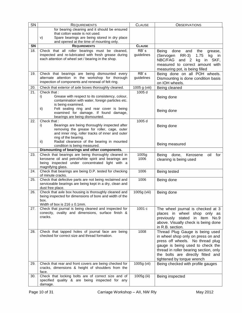
Page 10 of 31 Carriage Workshop – AII, NW Rly May 2012
SN REQUIREMENTS CLAUSE OBSERVATIONS for bearing cleaning and it should be ensured that cotton waste is not used.
v) Spare bearings are being stored in dry place and opened at the time of mounting only.
SN REQUIREMENTS CLAUSE 18. Check that all roller bearings must be cleaned,
inspected and re-lubricated with fresh grease during each attention of wheel set / bearing in the shop.
RB’ s guidelines
Being done and the grease, (Servogen RR-3) 1.75 kg in NBC/FAG and 2 kg in SKF, measured to correct amount with measuring pot, is being filled
19. Check that bearings are being dismounted every alternate attention in the workshop for thorough inspection of components and renewal of felt ring.
RB’ s guidelines
Being done on all POH wheels. Dismounting is done condition basis on IOH wheels.
20. Check that exterior of axle boxes thoroughly cleaned. 1005 g (viii) Being cleaned 21. Check that :
i) Grease with respect to its consistency, colour, contamination with water, foreign particles etc. is being examined.
ii) Felt sealing ring and rear cover is being examined for damage. If found damage, bearings are being dismounted.
1005 d Being done Being done
22. Check that : i) Bearings are being thoroughly inspected after
removing the grease for roller, cage, outer and inner ring, roller tracks of inner and outer ring of the bearing.
ii) Radial clearance of the bearing in mounted condition is being measured.
1005 d Being done
Being measured
Dismounting of bearings and other components. 23. Check that bearings are being thoroughly cleaned in
kerosene oil and petrol/white spirit and bearings are being inspected under concentrated light with a magnifying glass.
1005g 1006
Being done, Kerosene oil for cleaning is being used
24. Check that bearings are being D.P. tested for checking of minute cracks.
1006 Being tested
25. Check that defective parts are not being reclaimed and serviceable bearings are being kept in a dry, clean and dust free place.
1006 Being done
26. Check that axle box housing is thoroughly cleaned and being inspected for dimensions of bore and width of the box. Width of box is 216 ± 0.1mm.
1005g (viii) Being done
27. Check that journal is being cleaned and inspected for conecity, ovality and dimensions, surface finish & cracks.
1001 c The wheel journal is checked at 3 places in wheel shop only as previously stated in item No.9 above. Visually check is being done in R.B. section.
28. Check that tapped holes of journal face are being checked for correct size and thread formation.
1008 Thread Plug Gauge is being used in wheel shop only on press on and press off wheels. No thread plug gauge is being used to check the thread in roller bearing section, only the bolts are directly fitted and tightened by torque wrench
29. Check that rear and front covers are being checked for cracks, dimensions & height of shoulders from the face.
1005g (vii) Being checked with profile gauges
30. Check that locking bolts are of correct size and of specified quality & are being inspected for any damage.
1005g (iii) Being inspected
Page 11 of 31 Carriage Workshop – AII, NW Rly May 2012
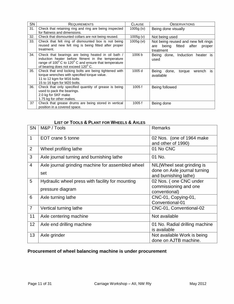
SN REQUIREMENTS CLAUSE OBSERVATIONS 31. Check that retaining ring and ring are being inspected
for flatness and dimensions. 1005g (iv) Being done visually
32. Check that dismounted collars are not being reused. 1005g (v) Not being used 33. Check that felt ring of dismounted box is not being
reused and new felt ring is being fitted after proper treatment.
1005g (vi) Not being reused and new felt rings are being fitted after proper treatment
34. Check that bearings are being heated in oil bath / induction heater before fitment in the temperature range of 100
0 C to 120
0 C and ensure that temperature
of bearing does not exceed 1200 C.
1006 b Being done, Induction heater is used
35. Check that end locking bolts are being tightened with torque wrenches with specified torque value. 11 to 12 kgm for M16 bolts 15 to 16 kgm for M20 bolts.
1005 d Being done, torque wrench is available
36. Check that only specified quantity of grease is being used to pack the bearings. 2.0 kg for SKF make 1.75 kg for other makes.
1005 f Being followed
37 Check that grease drums are being stored in vertical position in a covered space.
1005 f Being done
LIST OF TOOLS & PLANT FOR WHEELS & AXLES
SN M&P / Tools Remarks
1 EOT crane 5 tonne 02 Nos. (one of 1964 make and other of 1990)
2 Wheel profiling lathe 01 No CNC
3 Axle journal turning and burnishing lathe 01 No.
4 Axle journal grinding machine for assembled wheel
set
NIL(Wheel seat grinding is done on Axle journal turning and burnishing lathe)
5 Hydraulic wheel press with facility for mounting
pressure diagram
02 Nos. ( one CNC under commissioning and one conventional)
6 Axle turning lathe CNC-01, Copying-01, Conventional-01
7 Vertical turning lathe CNC-01, Conventional-02
11 Axle centering machine Not available
12 Axle end drilling machine 01 No. Radial drilling machine is available
13 Axle grinder Not available Work is being done on AJTB machine.
Procurement of Wheel balancing machine is under procurement

Page 12 of 31 Carriage Workshop – AII, NW Rly May 2012
LIST OF TOOLS & PLANT FOR ROLLER BEARINGS
SN M&P / Tools Remarks
1 Automatic roller bearing cleaning plant with 3-stage cleaning of pre-wash, wash and hot water rinsing.
Available
2 Axle box cleaning plant with bosch tank and spray jet cleaning in closed chamber, having conveyor facility
Closed chamber not available, cleaning is being done in open surroundings
3 Axle box extractor Mechanical screw type – 01 No.
4 Hydraulic dismounting equipment for direct mounted spherical roller bearing.
Available
5 Induction heater with demagnetizing device Available but without demagnetizing device.
6 Torque wrench and torque wrench tester. Available
7 Feeler gauge set. Available
8 Outside micrometer for journal and shoulder diameter measurement.
Available(both digital and non digital are available)
9 Three legged inside micrometer with 0.05mm least count for inner race bore Measurement.
Available
10 Magnifying glass with light. Available
11 Volumetric containers for grease. Available ( 06 Nos. of different sizes)
12 Thread ring gauges for end locking screw inspection.
M16x1.5 – 1 set available
13 Thread plug gauges for end locking holes. M16x1.5 – 1 set available
14 Engraving/etching machine. Engraving on bearing is being done with acid etching. Bearing details are available for wheel tag.
Page 13 of 31 Carriage Workshop – AII, NW Rly May 2012
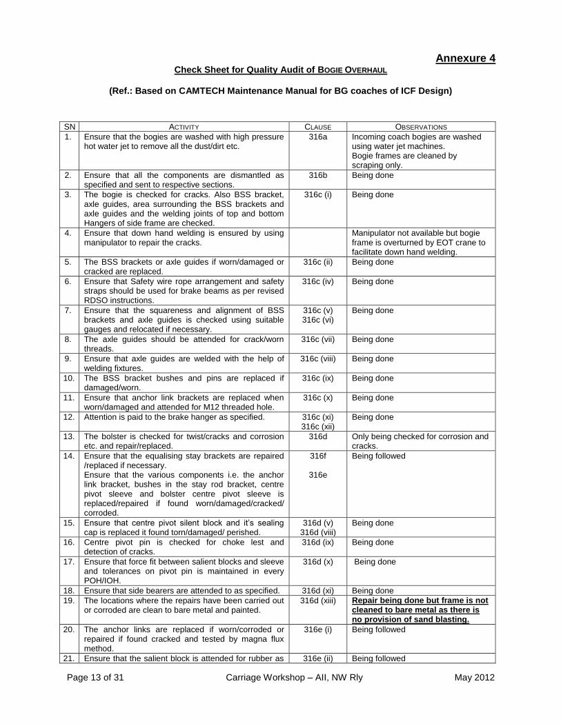
Annexure 4 Check Sheet for Quality Audit of BOGIE OVERHAUL
(Ref.: Based on CAMTECH Maintenance Manual for BG coaches of ICF Design)
SN ACTIVITY CLAUSE OBSERVATIONS
1. Ensure that the bogies are washed with high pressure hot water jet to remove all the dust/dirt etc.
316a Incoming coach bogies are washed using water jet machines. Bogie frames are cleaned by scraping only.
2. Ensure that all the components are dismantled as specified and sent to respective sections.
316b Being done
3. The bogie is checked for cracks. Also BSS bracket, axle guides, area surrounding the BSS brackets and axle guides and the welding joints of top and bottom Hangers of side frame are checked.
316c (i) Being done
4. Ensure that down hand welding is ensured by using manipulator to repair the cracks.
Manipulator not available but bogie frame is overturned by EOT crane to facilitate down hand welding.
5. The BSS brackets or axle guides if worn/damaged or cracked are replaced.
316c (ii) Being done
6. Ensure that Safety wire rope arrangement and safety straps should be used for brake beams as per revised RDSO instructions.
316c (iv) Being done
7. Ensure that the squareness and alignment of BSS brackets and axle guides is checked using suitable gauges and relocated if necessary.
316c (v) 316c (vi)
Being done
8. The axle guides should be attended for crack/worn threads.
316c (vii) Being done
9. Ensure that axle guides are welded with the help of welding fixtures.
316c (viii) Being done
10. The BSS bracket bushes and pins are replaced if damaged/worn.
316c (ix) Being done
11. Ensure that anchor link brackets are replaced when worn/damaged and attended for M12 threaded hole.
316c (x) Being done
12. Attention is paid to the brake hanger as specified. 316c (xi) 316c (xii)
Being done
13. The bolster is checked for twist/cracks and corrosion etc. and repair/replaced.
316d Only being checked for corrosion and cracks.
14. Ensure that the equalising stay brackets are repaired /replaced if necessary. Ensure that the various components i.e. the anchor link bracket, bushes in the stay rod bracket, centre pivot sleeve and bolster centre pivot sleeve is replaced/repaired if found worn/damaged/cracked/ corroded.
316f
316e
Being followed
15. Ensure that centre pivot silent block and it’s sealing cap is replaced it found torn/damaged/ perished.
316d (v) 316d (viii)
Being done
16. Centre pivot pin is checked for choke lest and detection of cracks.
316d (ix) Being done
17. Ensure that force fit between salient blocks and sleeve and tolerances on pivot pin is maintained in every POH/IOH.
316d (x) Being done
18. Ensure that side bearers are attended to as specified. 316d (xi) Being done
19. The locations where the repairs have been carried out or corroded are clean to bare metal and painted.
316d (xiii) Repair being done but frame is not cleaned to bare metal as there is no provision of sand blasting.
20. The anchor links are replaced if worn/corroded or repaired if found cracked and tested by magna flux method.
316e (i) Being followed
21. Ensure that the salient block is attended for rubber as 316e (ii) Being followed

Page 14 of 31 Carriage Workshop – AII, NW Rly May 2012
SN ACTIVITY CLAUSE OBSERVATIONS
well as force fit.
22. Ensure that the equalising stay rod and pin are attended as specified.
316 f Being followed
23. Clean the BSS hangers and check for cracks and wear. The hangers are replaced if wear exceeds 1mm.
316 h (i) Being followed
24. Ensure that the magna flux crack detection equipment is used for checking the cracks.
316 h (i) Being followed
25. Ensure that the repair to BSS hangers is done as specified.
316 h (ii) Not being repaired but unserviceable are replaced with new.
26. Hanger blocks are checked for cracks by magna flux test and worn hangers blocks are built up by using 2B electrodes and machined to size.
316 i Hanger blocks are being properly checked and magna-flux test is being done. Repair not being done instead unserviceable are replaced. Brake beam ends are being replaced if found unserviceable. However proper fixture needs to be used for checking the squareness.
27. Ensure that the entire components i.e. upper and lower rubber washer, packing rings, guide rings, dust shield, guide bush dust shield spring and spring clip are replaced.
316j (ii) Being followed
28. The lower spring seat is checked and replaced/reclaimed if necessary.
317 Being followed
29. The springs are cleaned thoroughly in Bosch tank. Bosch tank not available but springs are cleaned by scraping and shot blasting.
30. The springs are inspected by magna flux/chalk test to detect cracks.
Being followed
31. Each spring is subjected to incremental load as specified.
Being followed
32. After load deflection, the springs are painted. Being followed
33. The springs are grouped into three groups as per deflection.
Being followed
34. Ensure that brake levers/bushes are replaced. 318 Being followed
35. The components of brake gear such as worn brake beams, brake head shoes, brake gear pins are replaced/repaired.
Being followed
36. The brake gear pins should be used which are case hardened, crown finish and chromium plated.
318 Being followed
37. Ensure that maximum permissible clearance between brake gear pins and bush is 1.5mm.
Being followed
38. All the brake gear components are given two coats of red oxide primer, 4 coats of bituminous solution and one coat of anti-corrosive black paint.
Single coat of red oxide and bituminous is being given to few components only. Instructions to use many coats of paint need review.
39. Ensure that a sub, store is available in the shop to ensure supply of proper components and sub assembly for bogie assembly.
319a Sub stores is available
40. Ensure that during assembly cotters is spilitted min.mm.45” and not slack in the pins modified levers hanger pins are used to prevent the bush working of the lever hanger.
319b (ii) Being followed
41. Ensure that while tightening guide cap guide bush sits tight against the rubber packing ring and holes, in the guide are in alignment with corresponding holes in the guide bush.
Being done
42. Ensure that the wheel sets are selected in such a way that the variation in the diameter of the wheels in the same bogie and in the same coach does not exceed the specified limits.
319d (i) Being done
43. The assembled bogie should be load tested on a bogie test stand where it is lowered up to its normal
319d (v) Machine is available but not working.
It was reported that dimensions

Page 15 of 31 Carriage Workshop – AII, NW Rly May 2012
SN ACTIVITY CLAUSE OBSERVATIONS
working load and height of the bolster top surface from rail level should be measured for comparison with pre-determined dimension corresponding to correct coach buffer height.
checked and maintained on this machine change when coach body is lowered. Usefulness of this machine needs review.
44. Ensure that maximum modifications to different bogie components issued by RDSO are carried out during POH.
Appendix D Being done
SHOCK ABSORBERS :
1. Ensure that shock absorber are given POH when the capacity is beyond ± 20% of the specified value on after 4 lakhs kms or alternate POH which ever is earlier.
319f Being done
2. The shock absorber is tested to measure its capacity in both tension and compression by developing the existing force at a velocity of 10cm per sec.
Being done
3. Ensure that the shock absorbers are properly painted covered and stamped.
Being done
LIST OF TOOLS & PLANTS FOR BOGIES
LIFTING SHOP
Ball pen hammer Available
Chisel Available
Spanner Available
WASHING PLANT
Bosch tank Not Available
Hot water jet system Yes, available
Waste water treatment plant Not available
Bins and pallets Yes, available.
Jib crane EOT cranes of sufficient capacity are available.
Fork lift Yes, available.
Platform truck Yes, available
BOGIE SHOP
Ball pein hammer Available
Chisel Available
Standard spanner set Available
Welding transformer Available
Gas cutting plant Available
Bogie alignment gauges Available
Spring testing machine Available
Magna flux crack detector Available
Paint brushes Available
Floor scraper Available
Platform truck Available
Bogie test rig working stands Available
Overhead crane Available
Bins and pallets Available
Fork lift Available
FITTING SHOP

Page 16 of 31 Carriage Workshop – AII, NW Rly May 2012
Ball pein hammer Available
Chisel Available
Welding transformer Available
Gas cutting plant. Available
Hydraulic press Available
Measuring gauges Available
Centre lathe Available
Brake beam end turning m/c. Available
Electrode heater Available
BSS hanger testing machine Available
Bins and pallets Available
Fork lift Available
Platform truck Available

Page 17 of 31 Carriage Workshop – AII, NW Rly May 2012
Annexure 5 Quality Audit of
Maintenance for Brake Block Hanger for ICF coaches (Ref.: CAMTECH Maintenance Manual for BG coaches of ICF Design
& RDSO STR C9808 (Rev- 4) Corrigendum-1)
SN Requirements Observations
1 Railway must conduct audit checks on the new supply of brake hanger received by them and should maintain records
New supply is RITES inspected and are therefore not inspected by the shop.
2 Hanger should be removed from coaches during POH/IOH. They should be cleaned and checked visually for cracks, distortion or excessive corrosion. Hanger found serviceable should be
Checked for wear on the bore of the hole with the help of a plug gauge.
Magnaflux / chalk tested for any cracks before they are put into service.
It was not being done though plug gauge was available. Started from the day of audit. Being followed
Other observations: 1. TSO / LTO / Work instruction on maintenance of brake block hanger: Available. 2. Rejection of brake block hanger: : Record maintained by CMT – WI/FL/005 3. Average POH/IOH attention: 108+68 (POH+IOH) coaches per month. 4. Procurement during last three years is as under:
Year Total procurement in Nos.
2008-09 720
2009 -10 714
2010 -11 2243
2011- 12 2147
5. Procurement status of brake block hanger as per revised drawing: Since 09-10.
However, additional quantity against replacement of all old design hangers needs to be planned.
6. Details of brake block hangers checked and rejected are detailed as under:
Month BB hangers checked
Passed Rejected % rejection
Cause of rejection
Dimension Pitted M/flux
Aug.11 2434 2403 33 1.35 - - 33
Sept.11 3474 3425 49 1.4 02 - 47
Oct.11 2173 2160 13 0.51 - - 13
Nov.11 2701 2681 20 0.73 - - 20
Dec.11 3076 3054 16 0.52 01 - 15
Jan.12 2636 2606 30 1.13 - - 30
Feb.12 2386 2364 19 0.71 - - 19
March 2854 2828 26 0.9 - - 26
Page 18 of 31 Carriage Workshop – AII, NW Rly May 2012
12
7. Last quality audit done (Internal):-Yes.
8. Other observation:-Nil

Page 19 of 31 Carriage Workshop – AII, NW Rly May 2012
Annexure 6 Check Sheet for
Quality Audit of Interior fittings (Furnishings) (Ref.: Chapter 11 of CAMTECH Maintenance Manual for BG coaches of ICF Design)
SN Requirements Clause Observations
1.0 Interior fittings such as panels, seats, berths, windows, lights, fans, sanitary fittings, etc. should be furnished as per Rly/RDSO standard for various types and classes of vehicle.
1101 Being followed
2.0 Amenity Fittings – Various passenger amenities fittings
should be provided as per table no.11.1 of Chapter 11 of CAMTECH manual
1102 Being followed
3.0 Plastics, FRP and various other synthetic materials
are now a days used which are light in weight and requires less maintenance and give better aesthetics. Status of implementation during POH
1103
3.1 Roof Paneling Sheet: 2 mm thick limpet asbestos sheet or 1.5 mm thick NFTC should be used.
1103a Being followed
3.2 Side Wall Paneling: 3 mm thick thermosetting synthetic resin bonded decorative LP Sheets (C-9602) should be used.
1103b Being followed
Use of other Plastic Materials :
SMC moulded window shutters, Wall protector and Axle box cover
Plastic Push Cock made of HDPE, PTMT and acetal material..
1103c Being followed except wall protector and taps
4.0 Attention in Workshop :
Inspect interior fittings for corrosion and damage, Missing, defective fittings should be refitted/repaired.
All distorted/damaged panels should be replaced. No patch work allowed. While replacing the panels, care should be taken to match the colour and design.
After 5-7 years while attending corrosion on the roof sheets, deficient/damaged insulation should be replaced.
1103d Being followed Being followed but small patches observed in coach No. 7408 Cases of roof sheet corrosion are not observed.
5.0 Anti Pilferage Measures: To prevent theft, anti pilferage measures should be taken as advised by CME or RDSO.
1103e Being followed
6.0 Window 1104
6.1 Window of non-AC coaches –
Check balancing mechanism of glass shutter from dripping.
Check spring loaded safety latch to prevent Louvre shutter from falling
1104a Being followed Being followed
6.2 Window of AC Coaches : Sealed windows of both ICF or RCF design should meet the following requirement: 5.5 / 6 mm thick toughened safety glass (IS2553, Part-II) are used in window. A reflective sun control film of smoke grey colour is pasted on inside surface of outer glass.
1104b Being followed Being followed
6.3 Emergency openable window – It is provided as 4 nos. in Non AC coaches (3
rd window from both end).
2 nos. in AC coaches (3rd
window from both end)
1104c Being followed. However, the securing arrangement of chain for opening the window inside a small box with glass cover needs

Page 20 of 31 Carriage Workshop – AII, NW Rly May 2012
SN Requirements Clause Observations
review as it may be unworkable in case of emergency.
6.4 Lavatory Windows of Non AC coaches – FRP banjo type windows frosted glass are fitted in lab.
1104d Being followed
6.5 Lavatory windows of AC coaches – Sealed type windows with frosted glass are fitted in lavatory of AC coaches.
1104e Being followed
6.6 Maintenance of AC windows in workshops –
Replace broken, cracked, defected or scratched window.
Glass should be cleaned with lime and detergent before fitting.
The hinges of inner window frame should be checked well oiled before fitting.
The rubber beading between window and coach body should be replaced if found set, deteriorated or damaged to ensure air tightness.
The damaged FRP inner frames / holding frame should be replaced.
1104f Being followed Being done Being done Being done No broken FRP found
6.7 Maintenance of windows of non-AC coaches in workshops
All windows shutters should be fully removed from body shell at every 2
nd POH or when found defective
during pre-inspection.
When windows are not removed, the shutters should be checked for easy working by lifting and lowering them check, safety catches, rubber channels.
The entire window assembly should be dismantled and shutters removed. Broken or cracked glasses should be replaced with toughened glass.
Holes in the frames for safety catches , which have become oblong should either be plugged and re-drilled.
Torn, rusted or deteriorated wire gaze should be replaced by proper galvanized wire mesh.
The shutter should be checked for easy working in grooves after rubber channels are replaced. Balancing mechanism for the shutter should be dismantled and repaired.
Spring tension should be correctly adjusted such that the shutter can easily be lifted and positioned wherever required.
The wire gauge should be cleaned with a wire brush and blown with compressed air.
On body side door windows of Non AC coaches safety bars should be provided.
1104g Being replaced based on pre-inspection report. Being followed Being followed Not being followed as not workable. Full channel needs replacement. This needs review. N.A. being obsolete Being followed Being followed N.A. being obsolete Being followed
7.0 FLOOR 1105
7.1 Flooring arrangement in a coach –
The flooring in a coach consists of a compreg sub-floor covered with PVC sheet. It should be done as per proper ICF drawing.
1105b Being followed
7.2 Material description
12 mm thick compreg floor board as per RDSO Sp. No.C-9407 (Revised) type-II should be used whenever floor boards of complete coaches require replacement.
When only part of the floor is to be replaced, repair to
1105c Being followed Being followed

Page 21 of 31 Carriage Workshop – AII, NW Rly May 2012
SN Requirements Clause Observations
floor should be carried out by using plywood to IS-303-1975 Grade-A fully treated for protection against fungi, termite, marine bores and other insecticides and requirement of preventive treatment to IS:5539.
PVC flooring – 2 mm thick homogeneous vinyl flooring as per RDSO sp.no. C-8515 (Rev 2). Alternatively PVC flooring as per revised specification RDSO/2006/CG12 (Rev1) to be procured.
Adhesive – Neoprene based rubber adhesive of Dunlop S-758 or Fevicol SR-998 make or equivalent quality.
Being followed Fire retardant solvent based adhesive is used (ICF/MD/Spec-093&075). Instructions needs review.
7.3 Attachment & Fixing i) Laying procedure for sub flooring
12mm thick compreg floor board as per RDSO sp.no. C-9407 (Revised) type II should be laid properly in level to the cross member/trough floor. Compreg sheet should be coated with water sealing compound to Sp.no. IS:7084-1973.
Drill holes on the compreg floor board and cross member/trough floors and should be fixed by self tapping counter sunk screw as per drgs.
Any gap between compreg floor board should be filled with epoxy putty. Try to minimize the gap. 5 kgs of epoxy putty should be prepared as under: French Chalk - 2.1 kg Resin HSK - 2.1 kg Acetone commercial - 0.4 kg Accelerator - 0.2 kg Catalyst - 0.2 kg Total 5.0 kg
The self tapping screw head should also be leveled by applying epoxy putty.
The coach floor should be sweeped and cleaned thoroughly before laying the PVC floor sheets/rolls.
ii) Laying of PVC Flooring
PVC roll/sheet should be opened on half the width of coach and should be left for 30 to 40 minutes to enable it to lie flat on the floor.
Proper marking the position of pillars, seat frame etc on the PVC and cut neatly around the pillars and frames.
The roll should be folded half way and spread a thin and even layer of adhesive (Dunlop S-758 or Fevicol SR-998 make or equivalent) on the compreg sub-floor.
Adhesive should also be applied on the rough reverse side of PVC flooring thinly and evenly.
Approx. 30 minutes should be allowed for solvent evaporation to prevent solvent vapours being entrapped.
No welding operation should be allowed during laying of PVC as adhesive is flammable agent.
After adhesive work of 1st roll is over, apply pressure
with a steel roller of 25 kgs to obtain perfect adhesion between PVC flooring and compreg sub-floor and also to eliminate air being entrapped.
The 2nd
roll should be laid in position overlapping the 1
st sheet by about 5 to 10 mm while spreading the
1105d Water sealing compound is not being used. Its use needs review in view of properties of comprg floor board. Pan head screws are being used instead of CSK screws There is hardly any gap to fill any kind of putty. This needs review. Not needed as pan head screws are being used. Being done Being followed Being followed Solvent based adhesive is being used Being followed Being used Being used Being used

Page 22 of 31 Carriage Workshop – AII, NW Rly May 2012
SN Requirements Clause Observations
roll, it should be ensured that the cuts on PVC flooring match with pillars or partition and seat frames
. iii) Thermo – welding (Hot Air Welding)
Proper thermo welding of PVC flooring is necessary for obtaining satisfactory bonding/results.
iv) Grooving
A grooving tool (hand or automatic) along with a straight edge/scale should be used to groove the butting edges of the seam to approximately two third of the thickness of the wear layer of PVC flooring. v) Welding
Seams should be thermo welded with a hot air gun using flexible transparent vinyl welding cord. vi) Trimming
When the weld has cooled to room temperature, it should be trimmed off flush to the surface of the material with a trimming spatula.
Not being done in this manner. It was reported that such overlapping was not practical and it was rather recommended to lay two rolls with edges close to each other. This needs review. Being used Not being used as detailed above. Laying of PVC on the floor needs review. Being done. However, workmanship needs improvement. Being done
7.4 Lavatory Flooring
The cracked damaged or worn out PVC sheets should be removed and a new single piece PVC sheet should be pasted over stainless steel inlay. No patch work should be done in the lavatory flooring.
1105e Being done
7.5 Special Tools and Equipments
i) Hot air welding equipment – 750 watts capacity with control device on the torch. ii) Roller with handle for pressing the weld deposits. iii) Welding Rod 2 mm dia PVC electrode. iv) Recommended procedure for welding of flexible PVC-to IS : 8002 - 1976 v) Adhesive - Dunlop S-758 or Fevicol SR-998 make or equivalent vi) Water proof sealing compound to IS : 1580-1960
1105f Available Available Available Available Solvent based adhesive is being used Not being done
7.6 Maintenance Instructions
i) The cracked, damaged, or worn out PVC flooring sheets should be removed, Swollen or otherwise damaged floor boards should be renewed and a new PVC patch of same colour should be pasted. The joints of PVC patch should be properly thermo welded to prevent seepage of water. ii) The coaches undergoing corrosion repair should be provided with PVC flooring as per RDSO pamphlet no. C-9001.
1105g Being done Being done
8.0 Seats and Berths 1106
8.1 The upholstery material used for seats & berths of different classes of coaches should be provided as per latest guidelines of RB and RDSO
1106a Being followed
8.2 Maintenance in Workshops
The berths and seats found defective due to opening of stitches, cracks/tron/faded rexine or sagged cushion should be removed from coach and sent to Trimming shop for repairs.
1106b Being followed
Page 23 of 31 Carriage Workshop – AII, NW Rly May 2012
SN Requirements Clause Observations
After stripping the seats, backrest, berths, armrests, etc., completely the frame should be examined for distortion/crack.
Following measures should be taken to improve the quality of upholstery work. - Rounding of corners of berths and seats - Use of nylon sewing threads
- Use of straight edge rexine cutting machine - Use of pneumatic staplers.
Reclining Seats of Chair Cars - The reclining chairs should be removed from the
chair cars in every POH and sent to fitting and trimming shops for overhaul.
- After the Chairs are repaired and assembled, they should be tested for easy movement and firm securing in all reclining positions.
- The component should be painted all over except sliding and rotating surfaces which should be well greased.
- After assembly, the chair should be tested for ease or rotation and proper locking.
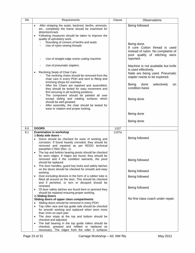
Being followed Being done. 9 core Cotton thread is used instead of nylon. No complaints of poor quality of stitching were reported. Machine is not available but knife is used effectively. Nails are being used. Pneumatic stapler needs to be explored. Being done selectively on condition basis Being done Being done Being done
9.0 DOORS 1107 9.1 Examination in workshop
i) Body side doors –
Doors should be checked for ease of working and corrosion. If found heavily corroded, they should be removed and repaired as per RDSO technical pamphlet C7602 (Rev -1)
The top and bottom bearing pivots should be checked for worn ridges. If ridges are found, they should be removed and if the condition warrants, the pivot should be replaced.
The door handles, guard key locks and safety latches on the doors should be checked for smooth and easy working.
Dust excluding devices in the form of a rubber tube is fitted all around on the door. This should be checked and if perished, or torn or decayed should be renewed.
Of door safety latches are found bent or jammed they should be repaired ensuring proper working.
ii) Sliding Doors Sliding doors of upper class compartments
Sliding doors should be removed in every POH.
Top roller race and top guide rails should be checked for smooth working and replaced when worn more than 1mm on each part.
The door stops at the top and bottom should be checked and adjusted.
The ball bearing in the top guide rollers should be checked, greased and refitted or replaced as necessary. The ridges from the roller V surfaces
1107a
Being followed
Being followed
Being followed
Being followed
Being followed
No first class coach under repair.

Page 24 of 31 Carriage Workshop – AII, NW Rly May 2012
SN Requirements Clause Observations
should be removed or, if worn too small, the rollers should be replaced.
The automatic lock, especially its lock casing should be checked for cracks at its flanges. If cracked, it should be replaced.
If the door operating rod is broken it should be replaced.
Thee pins of the lock should be cleaned, oiled and refitted.
The internal door locking latches and the tower bolts should be checked for ease of working.
Ensure that gap between the door and the panel does not exceed 4.5mm
Broken glass in the observation windows should be replaced.
Sliding doors of luggage vans
Sliding doors should be removed at every POH. All corroded and damaged panels, louvers and members should be cut out and replaced.
Roller assembly should be removed and stripped. It should be replaced if found worn beyond 3 mm.
Other component should be examined and repaired or replaced as required.
Perished / torn rubber sealing should be replaced.
After assembling the components, the moving parts of the assembly should be greased before fitting them in position on the door.
The bottom guide, door handle and door locking arrangement should be examined and repaired or replaced as required.
After repair, the door assembly should be checked preferably in a fixture for its alignment of the top rollers and the bottom guide.
iii) Vestibule Doors
a) sliding doors – these should be attended as given in section (ii) above
b) Flap doors – they should be checked for ease of working damage to their panels, hinges, locking bolts and other parts and necessary repairs carried out.
c) Rolling shutters – they should be checked for ease of working and damages and necessary repairs carried out.
It should be ensured be ensured that the locking arrangement for the sliding doors / flap doors / rolling shutters are provided and are in working condition. iv) Corridor inter communication doors of air conditions coaches –
All damaged or perished lining should be replaced to ensure proper sealing. Door closer should be tested and defective door closer should be overhauled before fitting.
Being removed only when
defective
Being removed only when
defective
Being followed
Being followed
Being followed
Fixture not available for checking
the alignment which is done in-
situ.
Being followed
Being followed
Being followed
Being followed
10.0 VESTIBULE 1108

Page 25 of 31 Carriage Workshop – AII, NW Rly May 2012
SN Requirements Clause Observations
10.1 UIC type rubber vestibule (RDSO sketch-99056) and
foot plate arrangement i) Conversion of UIC type vestibule ii) The existing stock may be provided with
UIC type vestibule as per RDSO SK-99056.
1108a All stock being turned out with UIC fitment
10.2 Maintenance during POH
Steel frame complete should be examined for deformation corrosion. Defective components should be repaired. The deformed vertical channels should be straightened by heating and putting inwards by suitable chain and screw tensioning mechanism.
LP sheet should be examined on the inside of frame. If found dirty and stained, should be washed and cleaned. For vestibules without LP sheet, painting may be done.
Conditions of upper and lateral rubber flanges should be examined for wear or cuts. The cracked portion up to 300mm on lateral side flange may be repaired by rubber patch and rubber solution. It should be replaced if found beyond repair.
The fixing screws and nuts for rubber flanges should be examined. It should be tighten if found loose or should be replaced if found missing.
The support brackets for foot plate should be examined. The deformed or corroded brackets which are beyond repair should be replaced. Perished or missing rubber sheets should be replaced.
The foot plate should be cleaned with wire brush to remove muck, dirt etc. the foot plate arrangement should be examined for wear, deformation or corrosion. If found beyond repair foot plate should be replaced. Broken bearing piece, holding bracket, pins should be examined for wear, broken or welding crack. The foot plate should be painted with anti corrosive paint.
The holding device for foot plate should be examined. It should be replaced/repaired as per requirement. The hand rail should be examined for breakage etc.
The bracket assembly and connecting components (if provided ) should be examined for coupling the UIC vestibules with conventional vestibules. Reformed or missing components should be replaced.
After completion of repairs all components should be painted with one coat of red oxide zinc chromate primer.
1108(b) Being followed
Being followed
Upper rubber flanges broken/deficient not being replaced Being followed
Being followed
Being followed, fall plates with slight worn out checks are made good by welding or being replaced Being followed
N.A. Being followed
11 Provision of upgraded material in coaches with 18 month POH interval. Items as per enclosed annexure are procured and fitted.
Being done(PVC, Sunmica panel, Rexine and curtains of upgraded material being used)

Page 26 of 31 Carriage Workshop – AII, NW Rly May 2012
Annexure 7 Quality audit of air brake system
(Ref.: Maintenance Manual G-97 of Air Brake System for Freight Stock as well as Chapter 4 &6 of CAMTECH Maintenance Manual for BG coaches and Chapter 8 of CAMTECH Maintenance Manual
for Wagon)
SN Requirements Clause Remarks 1.0 Distributor Valve (Annexure-I of G-97). 1.1 Check that dismantling/assembly of DV
assembly and Pipe bracket is being done as per maintenance manual of respective manufacturer.
2.1of G 97 415&416 CAMTECH
Being followed
1.2 Check that all the components have been replaced of POH kit irrespective of condition.
2.2 of G 97 ANNNEXURE 4.1 &4.2 CAMTECH
Being followed. However, kits include only 54 items and some of the items such as springs are not the part of any of the kits. There is no set system to replace such items out out the kit of 54 items before failure. Shop has proposed another kit (B) consisting of 22 such items which is under stocking. Transportation of DVs from section to the coach needs to be in proper box to avoid damage/ingress of dirt.
1.3 Check that DVs have been tested for all the parameters as given in their format on a test bench.
3.1of G 97 415f,416b,417 CAMTECH
Being followed
1.4 Check that pipe bracket is being tested for leakage with 10 kg/cm
2 air pressure.
3.2 of G 97
Being followed
1.5 DV of BOBRN/BOBR wagon shall be tested for parameters as covered in Annexure – XII
3.3 of G 97 N.A.
1.6 The distributor valves not meeting any of the requirements must be attended as per procedure covered in manufacturer maintenance manual and retested for all parameters.
3.4 of G 97 Being followed
1.7 Check that overhauled DVs are being stenciled as below (i) Workshop & Railway. (ii) Month & Year.
4 of G 97 Being done
1.8 Check that overhauled and tested DVs are being stored in a clean & dry place.
5 (I) of G 97
Being followed
1.9 Check that all inlet points of DV & pipe bracket are covered with protective cap.
5(II) of G 97
Being done
1.10 Check that specified tools are available for DV repair.
6 of G 97 415d CAMTECH
Available
1.11 Check that overhauling is being done by trained persons
8 of G 97
Being done
2.0 Bogie Mounted Brake Cylinder 608 CAMTECH
2.1 Brake cylinder is dismantled as specified with correct tools
608a CAMTECH
Being done
2.2 Check that all the components of brake cylinder have been thoroughly degreased and cleaned.
608g CAMTECH
Being done
2.3 Check that all the components have been thoroughly inspected for damage, cracks or welding, dent etc and ensure that damaged components have been replaced.
608g CAMTECH
Being done
Page 27 of 31 Carriage Workshop – AII, NW Rly May 2012
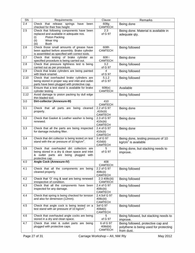
SN Requirements Clause Remarks 2.4 Check that release springs have been
checked for their free height 608g
CAMTECH Being done
2.5 Check that following components have been replaced and available in adequate nos. (i) Piston Packing (ii) Wear ring (iii) Bush
2.3 of G 97
Being done. Material is available in adequate qty.
2.6 Check those small amounts of grease have been applied before assembly. Brake cylinder is assembled as specified with correct tools.
608h CAMTECH
Being followed
2.7 Check that testing of brake cylinder as specified procedure is being carried out.
608 i CAMTECH
Being done
2.8 Check that pressure tightness test is being carried out as per procedure.
3.2 of G 97
Being followed
2.9 Check that brake cylinders are being painted with black enamel.
4 of G 97
Being followed
2.10 Check that overhauled brake cylinders are being stored in proper way and inlet and outlet parts have been plugged with protective cap.
5.1.2 of G 97
Being followed
2.11 Ensure that a test stand is available for brake cylinder testing
608(e) CAMTECH
Available
2,12 Avoid damage to piston packing by dull edge thin bladed tool.
Being followed
3.0 Dirt-collector (Annexure-III) 410 CAMTECH
3.1 Check that all parts are being cleaned properly.
2.2 of G 97 ,410c(ii) CAMTECH
Being done
3.2 Check that Gasket & Leather washer is being renewed.
2.3 of G 97 410c(iii) CAMTECH
Being done
3.3 Check that all the parts are being inspected for damage including filter.
2.4 of G 97 410c(ii) CAMTECH
Being done
3.4 Check that dirt collector is being tested on test stand with the air pressure of 10 kg/cm
2.
3 of G 97 410d(ii) CAMTECH
Being done, testing pressure of 10 kg/cm
2 is available
3.5 Check that overhauled dirt collectors are being stored in a dry & clean space and inlet & outlet parts are being plugged with protective cap.
5 of G 97
Being done, but stacking needs to improve.
4.0 Angle Cock (Annexure-IV) 408 CAMTECH
4.1 Check that all the components are being cleaned properly.
2.2 of G 97 408c(ii) CAMTECH
Being followed
4.2 Check that ‘O’ ring & seat are being renewed irrespective of condition.
2.3 408c(iii) CAMTECH
Being followed
4.3 Check that all the components have been inspected for any damage.
2.4 of G 97 408c(iii) CAMTECH
Being followed
4.4 Check that spring is being checked for tension and also for dimension (12mm).
2.4.5of G 97 408c(iii) CAMTECH
Being followed
4.5 Check that angle cock is being tested on a test stand with air pressure of 10 kg/cm
2.
3of G 97 408d(ii) CAMTECH
Being followed
4.6 Check that overhauled angle cocks are being stored in a dry and clean space.
5 of G 97
Being followed, but stacking needs to improve.
4.7 Check that inlet & outlet parts are being plugged with protective caps.
6 of G 97 408d(iii)
CAMTECH
Being followed, protective cap and polythene is being used for protecting from dust.

Page 28 of 31 Carriage Workshop – AII, NW Rly May 2012
SN Requirements Clause Remarks 5.0 Auxiliary Reservoir(Annexure-V) 411 5.1 The auxiliary reservoir should be overhauled
in every POH. Check that auxiliary reservoir is being cleaned from outside and inside with wire brush and dry air jet after properly draining.
2.1of G 97 411a &c(ii) CAMTECH
Being done
5.2 Examine for visual damages. The auxiliary reservoir having deep cuts on surfaces may be rejected.
2.2of G 97 411c(ii) CAMTECH
Being done
5.3 Check that rust preventive is being applied from inside surface of reservoir.
2.3 of G 97 411c(ii) CAMTECH
Its applicability needs review.
5.4 Check that reservoir is being painted with black enamel from outside.
2.4of G 97 411c(ii) CAMTECH
Being done
5.5 Check that leather washer is being replaced irrespective of condition.
2.6of G 97 411c(iii) CAMTECH
Instead of leather washer ‘O’ Ring is being used
5.6 Check that Teflon tape is being used over drain plug for making leak proof joints.
2.7of G 97 411c(iv) CAMTECH
Being followed
5.7 Check that reservoirs are being tested with 10 kg/cm
2 hydraulic & air pressure for leakage.
3of G 97 411d(i&ii) CAMTECH
Being followed, hydraulic pressure of 16 kg/cm
2 &
air pressure of 10
kg/cm2 is being used
5.8 The auxiliary reservoir should be stored in such a way to prevent the following:
a) Damage due to hitting each other. b) The flange surface should be
prevented from damages. c) Outside paint should not be
damaged. d) Check that parts are being plugged
with protective caps
5 of G 97 411e
Being followed
6.0 Hose Coupling (Annexure-VI) 407 CAMTECH
6.1 Check that hose coupling is being thoroughly inspected for any damage, corroded and ensure that damaged hose are not being used.
2of G 97 407 CAMTECH
Being done
6.2 Remove the gasket and thoroughly clean the coupling head specially the internal groove for housing gasket.
2.3 of G 97
Being done
6.3 Check that hose coupling are being tested for leakage at the air pressure of 10 kg/cm
2.
3 of G 97 407b CAMTECH
Being done
6.4 Check that hose coupling are being stored at dry & clean space and outlet & inlet parts are being plugged with protective caps.
5 of G 97
Being done
7.0 Guards Emergency Brake Valve(Annexure-VII)/ GEBV
412 CAMTECH
7.1 Check that valves are being properly cleaned with the help of wire brush.
2.1of G 97 412c(ii) CAMTECH
Being followed
7.2 Dismantle the valve completely as per manufacturer’s procedure.
412c(i) CAMTECH
Being followed
7.3 Check that ‘O’ ring & sealing ring are being replaced.
2.3of G 97 412c(iii) CAMTECH
Being followed
7.4 Check that valves are being tested in accordance with manufacturer’s
3 of G 97 412d CAMTECH
Being followed
7.5 Check that overhauled valves are being stored properly and inlet & out parts are being plugged with protective caps.
5 of G 97 412e CAMTECH
Being followed, but stacking needs to improve.

Page 29 of 31 Carriage Workshop – AII, NW Rly May 2012
SN Requirements Clause Remarks 8.0 Isolating Cock (Annexure-VIII) 422 8.1 Check that isolating cocks are being
overhauled and tested in accordance with manufacturer’s maintenance manual.
2&3of G 97 422b&c CAMTECH
Being followed
8.2 Check that equipment for testing is available. 4 of G 97 Being followed 8.3 Check that repaired valves are protected from
dust & moisture. 5 of G 97 Being followed
9.0 Pipes, Joints & Support bracket (Annexure-X)
9.1 Check that gasket is being removed from flange joints and old one is scrapped.
2.1 of G 97
Being done
9.2 Check that pipes & joints are being cleaned from outside.
2.2 of G 97
Being done
9.3 Check that pipes & joints are being cleaned the inside by jet of dry air & all dirt and other particles are being removed.
2.3 of G 97
Being done
9.4 Check that gaskets groove of flange joints is being properly cleaned.
2.6 of G 97
Being done
9.5 Check that pipe is painted from outside. 2.8 of G 97 Being done 9.6 Check that pipes & joints are being re-cleaned
by dry air at least 5 minutes. 2.9
of G 97 Being done
9.7 Check that ends of the pipes are being plugged with protection caps and are being only removed at the time of fitment.
2.10 of G 97
Being done though protective capping is not 100%
9.8 Check that testing of the pipe is being done with 10 kg/cm
2 dry air pressure before
removal and after refitment.
3 of G 97
Being done
9.9 Check that removed pipes are being kept in set and are being fitted on same coach.
5 of G 97
-
9.10 Check that all gaskets are being renewed. 6 of G 97
Being done
10.0 Others: 10.1 POH kit for C3W and KE design DV as listed
in annexure XIII/1 & 3 are stocked at depot G 97 Yes, stocked at depot
10.2 POH kits of other air brake components as listed in annexure are stocked at depot.
G 97 Yes, stocked at depot
11.0 Slack adjuster 11.1 Overhauling facility for slack adjuster is
available and all Tools & equipments are available.
812 (C)(a) CAMTECH
N.A. as only BMBC is available
11.2 The slack adjuster shall be overhauled at the time of POH of rolling stock. While dismantling or assembling it is essential to use special tools . Each component of slack adjuster shall be examined. Worn out parts shall be checked according to the limits.
812 (C)(b) CAMTECH
N.A. as only BMBC is available
11.3 Any spring which does not conform to the requirements should not be used.
812 (C)(b)-I CAMTECH
N.A. as only BMBC is available
11.4 During POH must change items as per G-92 should be replaced
812 (C)(a)-II CAMTECH
N.A. as only BMBC is available
11.5 After cleaning and inspection, all parts of slack adjuster should be coated with semi fluid grease SERVOGEM-2 or equivalent before undertaking re-assembly
812 (D) CAMTECH
N.A. as only BMBC is available
11.6 The following should be ensured: a) The place of overhauling must be clean
and free from dust. b) Ensure that no foreign matter/particle
remain inside the subassemblies during re-assembly
812 (E) CAMTECH
N.A. as only BMBC is available

Page 30 of 31 Carriage Workshop – AII, NW Rly May 2012
SN Requirements Clause Remarks c) All rubber gasket, sealing ring, washers
must be replaced during overhauling. d) Specified tools and fixtures be used for
disassembly and assembly operations.
11.7 After overhauling, the testing of slack adjuster is carried out in a test rack for take up (Pay in test) and Pay out test
812 (F) CAMTECH
N.A. as only BMBC is available
11.8 The slack adjuster is given a coat of anti-corrosive paint, excluding the adjuster tube 41
812 (G) CAMTECH
N.A. as only BMBC is available
11.9 A & e dimension are adjusted correctly during brake rigging setting.
812 (H) CAMTECH
N.A. as only BMBC is available
12.0 Passenger assembly alarm signal device for coaches (Chapter IV of CAMTECH)
12.1 The passenger emergency alarm signal device should be completely dismantled and overhauled during every POH
419a Being done
12.2 The tools and fixtures required for overhauling of PEASD are available.
419b Yes, available
12.3 The passenger emergency alarm signal device after removing from the coach should be disassembled as specified
419c Being done
12.4 Cleaning of Parts
Clean all the metallic parts using kerosene or equivalent solvent.
Dry all the components using low pressure compressed air.
Ensure smooth scratch less finish of the bore for the displacement of the piston assembly.
419d Being done
12.5 Replacement of Parts
Inspect all moving parts for abnormal wear, tear, crack and deformation.
Replace the part if found defective. Replace the ‘O’ ring and other rubber
parts. Replace the spring of ramp in case of
cracks, kinks or permanent set. Replace damaged threaded screws
419e Being done
12.6 Assembly
To assemble the passenger emergency alarm signal device follow the instruction for disassembly in the reverse sequence.
Lubricate the pivot, roller and moving parts and ensure smooth operation of the components.
419f Being done
12.7 Passenger emergency alarm signal device are tested for leakage test and functional test as specified. Test bench is available.
419g Being done
13.0 Passenger emergency alarm valve (PEAV) (Chapter IV of CAMTECH)
420 of CAMTECH
13.1 For effective and reliable functioning overhauling should be done every POH
420a Being done
13.2 Tools and fixtures as specified for overhauling are available.
420b Yes, available
13.3 PEAV is overhauled as per specified procedure.
420c & d Being done
13.4 During scheduled overhauling all rubber and rubber bonded parts should be replaced
420e Being done

Page 31 of 31 Carriage Workshop – AII, NW Rly May 2012
SN Requirements Clause Remarks 13.5 Passenger emergency alarm valve are tested
for electric test, leakage test and functional test as specified. Test bench is available.
420g Yes, available
14.0 Check valve (Chapter IV of CAMTECH) 421 of CAMTECH
14.1 The check valve with choke is completely dismantled and overhauled once in every POH
421 Being done
14.2 Tools and fixtures as specified for overhauling are available.
421a Yes, available
14.3 Check valve is overhauled as per specified procedure
421b Being done
14.4 Replacement of Parts Replace all rubber parts. Replace the spring if it has kinks or crack
mark or if the spring has lost its stiffness or is heavily corroded.
Replace the choke of 3mm if screwing slot is damaged or threads are heavily corroded.
Inspect the valve seat of body for any minor scratch and lap the seat to remove such scratch marks.
421b (iii) Being done
14.5 After overhauling fix the check valve with choke on the test bench and test as per procedure.
421b (v)
Being done
15.0 ISOLATING COCK (Chapter IV of
CAMTECH) 422
15.1 The isolating cocks are to be completely dismantled and overhauled once in every POH
422 Being done
15.2 Tools and fixtures as specified for overhauling are available
422a Being done
15.3 Isolating cocks are overhauled as per specified procedure Replace all rubber parts and gland packing etc
422b Being done
15.4 After overhauling isolating cocks are tested on the test bench as per procedure.
422c Being done