Embed Size (px)
Citation preview

NWC TP 692"
N
Pyroshock Data Acquisition and Analysis forU/RGM-109D Payload Cover Ejection Tests
byAllan G. Piersol
Astron Research and Engineeringfor
Engineering Department
SEPTEMBER 1988
NAVAL WEAPONS CENTERCHINAAKE, CA 93555-6001 DTIC
S'ELECT:\jj DE 271 9S0U
Approved for public release; distribution is unlimited.
90 ' 'W 051
Naval Weapons Center
FOREWORDThis is a final report on the U/RGM- 109 payload cover ejection pyroshock data
acquisition and analysis. The work, authorized by the Naval Air Systems Command andfunded by AIRTASK PMA-2805A-88-01 under Contract No. N60530-87-D-0089, wasperformed from January 1987 to March 1988.
In the interest of economy and timeliness in presenting the information, the reportis being published as originally submitted.
This report was reviewed for technical accuracy by Ronald G. Merritt.
Approved by Under authority byS. HAALAND, Head J. A. BURTEngineering Department Capt., USN16 September 1988 Commander
Released for publication byG. R. SCHIEFERTechnical Director
NWC Technical Publication 6927
Published by ............................................................. Technical Information DepartmentC ollation ............................................................................................... C over, 13 leavesFirst printing .................................................................................................. 155 copies

UNCLASSIFIEDSECURITY CLASSIFICATION OF THIS PAGE
REPORT DOCUMENTATION PAGEla. REPORT SECURITY CLASSIFICATION lb. RESTRICTIVE MARKINGS
Unclassified2a. SECURITY CLASSIFICATION AUTHORITY 3. DISTRIBUTION / AVAILABILITY OF REPORT
2b. DECLASSIFICATION / DOWNGRADING SCHEDULE A Statement.
4. PERFORMING ORGANIZATION REPORT NUMBER(S) 5 MONITORING ORGANIZATION REPORT NUMBER(S)
7141-01 NWC TP 6927
6a. NAME OF PERFORMING ORGANIZATION 6b OFFICE SYMBOL 7a. NAME OF MONITORING ORGANIZATION
Astron Research and Engineering (it applicable) Naval Weapons Center
6c. ADDRESS (City. State, and ZIP Code) 7b. ADDRESS (City, State, and ZIP Code)
Santa Monica, CA 90404 China Lake, CA 93555-6001
8a. NAME OF FUNDING / SPONSORING 8b OFFICE SYMBOL 9. PROCUREMENT INSTRUMENT IDENTIFICATION NUMBER
ORGANIZATION (if applicable)
Naval Air Systems Command Contract No. N60530-87-D-0089ac. ADDRESS (City, State, and ZIP Code) 10. SOURCE OF FUNDING NUMBERS
PROGRAM PROJECT TASK WORK UNIT
Washington, DC 20630-5460 ELEMENT NO. NO. NO PMA- ACCESSION NO
I I2805A-88-01
i TITLE (Include Security Classification)
PYROSHOCK DATA ACQUISITION AND ANALYSIS FOR U/RGM-109D PAYLOAD COVER EJECTIONTESTS (U)2. PERSONAL AUTHOR(S) Piersol, Allan G.
i3a. TYPE OF REPORT 13b. TIME COVERED 14. DATE OF REPORT (Year, Month, Day) 15. PAG COUNTFinalFROM 87 Jan TO 88 Mar 1988. September 21
16. SUPPLEMENTARY NOTATION
17. COSATI CODES 18 SUBJECT TERMS (Continue on reverse if necessary and identify by block number)
FIELD GROUP SUB-GROUP Tomahawk Shock Environments, High Frequency (Pyroshock),
Shock Spectrum
19 ABSTRACT (Continue on reverse ilnecessary and identify by block number)
During the second development test flight of the U/RGM-109D Tomahawk cruise missile, a malfunction occurred in the Cruise MissileGuidance Set (CMGS) that is believed to have been initiated by the pyroshock loads resulting from the ejection of the payload bay covers. Thismalfunction motivated an extensive program of ground tests designed to simulate the pyroshock envrionment seen by the CMGS due to thepayload bay cover ejection event. During the course of these tests, a number of problems were encountered in obtaining reliable measurementsand assessments of the pyroshock data. Through a collective action by the major participants in the U/RGM- I09D program,many of theseproblems have now been resolved, and reliable data defining the pyroshock loads on the CMGS and its components due to the payload baycover ejection event have been established. These data provide a baseline for a definition of a shock specation of CMGS components, as wellas for continued experimental studies of the ruggedness of components to pyroshock loads. This report details the fundamental problemsassociated with the measurement of pyroshock environments using piezoelectric acceleromenters, and summarizes the actions taken tosuppress these problems in the measurements made during the various U/RGM- 109D ground tests simulating the payload bay cover ejectionevent.
20. DISTRIBUTION / AVAILABILITY OF ABSTRACT 21. ABSTRACT SECURITY CLASSIFICATION[ UNCLASSIFIED/UNLIMITED F] SAME AS RPT. -1 DTIC USERS Unclassified
22a. NAME OF RESPONSIBLE INDIVIDUAL 22b TELE PHONE Include Area Code) 22c. OFFICE SYMBOLW. Ned Jones 619-939-4659 3665
DD FORM 1473, 84 MAR 83 APR edition may be used until exhausted. SECURITY CLASSIFICATION OF THIS PAGE
All other editions are obsolete. UNCLASSIFIED* U.S. Govomvent PrInting Office: 198S--507-047
UNCLASSIFIEDSECURITY CLASSIFICATION OF THIS PAGE
UNCLASSIFIEDSECURITY CLASSIFICATION OF THIS PAGE
NWC TP 6927
CONTENTS
Introduction--------------------------------------------------------1I
Background-------------------------------------------------------- IMeasurement Transducers------------------------------------------- 2
Accelerometer Amplifiers and Lowpass Filters----------------------------- 4
Mechanical Lowpass Filters------------------------------------------ 5
Data Recording and Storage------------------------------------------ 5Anti-Aliasing Filters----------------------------------------------- 6
Data Analysis --------------------------------------------------- 7
Tests And Experimental Studies----------------------------------------- 10
GDC Backyard Tests---------------------------------------------- 10MDAC Welded Body Structure Tests-----------------------------------11
Litton NTS Plate Tests--------------------------------------------- 12
NWC Plate Tests------------------------------------------------- 12
NWC Standard Tape---------------------------------------------- 14
Recommended Procedures--------------------------------------------- 15
Transducers---------------------------------------------------- 15
Signal Conditioning And Recording ----------------------------------- 16Data Sampling And Editing ----------------------------------------- 17
Data Analysis--------------------------------------------------- 18
References-------------------------------------------------- 19Aaaession ForNTIS GRA&i-DTIC TAB0
Unannounced 53
DistributIon/
Avatibility Cod~es
IAvall and/orDist po1I
NWC TP 6927
FIGURES
1. Typical Acceleration Time History For A Pyroshock Event ------------------- 2
2. Pyroshock Acceleration Time History With High Frequency ComponentDue To Accelerometer Resonance ------------------------------------ 3
3. Pyroshock Acceleration Time History With Typical Zero OffsetDue To Accelerometer And/Or Amplifier Saturation ------------------------ 5
4. Illustration Of Shock Response Spectrum Measurement ---------------------- 7
5. Maximax SRS For U/RGM-109D Payload Cover Ejection Event -------------- 8
6. Maximax SRS For Sinusoidal Forcing Functions With A DurationEqual To An Integer Number Of Half Cycles ---------------------------- 9
7. Data Acquisition And Analysis System For GDC Backyard Tests --------------- 10
8. Data Acquisition And Analysis System For MDAC CMGS Tests --------------- 12
9. Data Acquisition And Analysis System For NTS RMUC Tests ---------------- 12
10. Pyroshock Acceleration Time History Showing Pre-Shock Event -------------- 13
ii

NWC TP 6927
INTRODUCTION
The land attack version of the Tomahawk cruise missile (U/RGM-109D) incorporates apayload bay that extends forward to about missile Station 26, approximately 8 inches aft of a bulk-head at Station 18.35 where the Cruise Missile Guidance Set (CMGS) is mounted. The payloadbay covers, one on each side of the vehicle, are severed around their perimeters and jettisoned inflight using a Flexible Linear Shaped Charge (FLSC) that is packed into grooves in the covers.This payload cover ejection event results in a strong pyrotechnic transient (pyroshock) thatconstitutes a significant dynamic load on the CMGS equipment.
During the second development test flight of the U/RGM- 109D missile (Mission D- 1 :DT-5),the CMGS malfunctioned and the missile crashed shortly after the payload cover ejection event.There is strong evidence that the malfunction was due to a pyroshock induced soft failure of theCMGS, specifically, a memory alteration in the CMGS Refenrnce Measuring Unit and Computer(RMUC) [1]. This malfunction initiated not only a detailed investigation of the specific failure, butalso an extensive study of improved procedures for the measurement and interpretation of pyro-shock data.
Pyroshock induced structural response data constitute one of the most difficult dynamicphenomenon to measure in practice. In particular, the basic characteristics of pyroshocks imposemechanical requirements that exceed the capabilities of commonly used motion transducers(accelerometers). This fact has lead to difficulties in the investigation and solution of the U/RGM-109D payload cover ejection shock problem. Nevertheless, considerable progress has been made inthe measurement and interpretation of the pyroshock data collected during the various experimentsperformed by the major participants in the program, namely, the General Dynamics-Convair (GDC)Division, the McDonnell Douglas Astronautics Company (MDAC), Litton Industries Guidance andControl Systems Division (Litton), and the Naval Weapons Center (NWC), China Lake. Thepurpose of this document is to clarify the basic problems related to the measurement of pyroshocks,summarize the results of experimental studies of transducers and techniques, and detail recommen-dations for the appropriate measurement and interpretation of pyroshock data that evolved fromthese studies.
The report is divided into four sections, including this introductory section. The secondsection presents background material on the general problems associated with pyroshock measure-ments, supported by appropriate references. The third section summarizes the various pyroshocktests and experiments performed to date by the primary participants in the study of the U/RGM-109D payload cover ejection problem. The concluding section details specific recommendationsconcerning pyroshock measurements on the U/RGM- 109D program.
BACKGROUND
The term pyroshock (or pyrotechnic shock) generally refers to the severe mechanical tran-sients caused by the detonation of an ordnance device on a structure. Such devices (linear shapedcharges, primacord, mild detonation cord, explosive bolts, etc.) are widely used to accomplish thein-flight separation of structural elements on aerospace vehicles [2]. A typical pyroshock accelera-tion time history record is shown in Figure 1.

NWC TP 6927
4x O-3
oo 2x10³ -
0
4.)
0 - p
U-U 3
-2x10-
-4x10³-2 0 2 4 6 8
Time, msec
FIGURE 1. Typical Acceleration Time History For A Pyroshock Event.
The basic characteristics of pyroshocks are similar to the ballistic shocks caused by theimpact of non-penetrating projectiles on a hard structure [31, in that they produce a near instan-taneous velocity change of the structure at the moment of impact. Hence, the acceleration responseof the structure near the point of impact approaches a true impulse or delta function; i.e., anacceleration that momentarily approaches an infinite value at the instant of impact [4]. The result isthe generation of intense stress waves that propagate throughout the structure, some in a non-dispersive manner at the speed of sound in the material (longitudinal and torsional waves), andothers in a dispersive manner at a "group velocity" that is dependent upon the geometry of thestructure and frequency (bending waves) [5]. Discountinuities in the structural propagation path(in particular, bolted or riveted joints) will strongly reflect and attenuate bending waves. Also, thedispersive character of bending waves causes them to spread in time with increasing distance fromthe source, reducing the sharpness of the wave front. On the other hand, longitudinal waves tend topropagate more easily through discontinuities, and with smaller loss factors. In either case, how-ever, when the measurement location is near the pyrotechnic source, as is the case in the U/RGM-109D payload cover ejection problem, the accurate measurement of the structural response to thepyroshock constitutes a major challenge.
MEASUREMENT TRANSDUCERS
Most pyroshock measurements are made using either piezoelectric or piezoresistive (straingage) type accelerometers. In either case, the accelerometer essentially consists of a lightly dampedresonant element that functions theoretically like a seismic accelerometer [6; 7, p.327]; i.e., ittranslates an acceleration at the base of the transducer into an electrical signal (charge or voltage)that is proportional to acceleration in the frequency range well below the resonance frequency of thesensing element. As long as the structural response being measured has no significant energy in thefrequency range near the resonance frequency of the sensing element, the transducer (if properlyused) will generally yield an accurate measure of the acceleration time history at its base. However,if there is significant energy in the frequency range of the sensing element resonance, the elementwill "ring" causing a strong transducer output signal at that resonanc - frequency, which may bemuch stronger than the true acceleration signal. The resonance frequencies of other mechanicalelements of the transducer, such as the casing, will cause the same effect.
2
NWC TP 6927
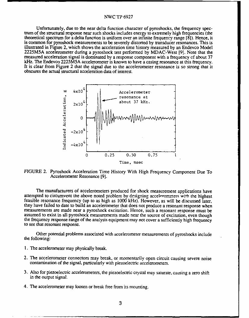
Unfortunately, due to the near delta function character of pyroshocks, the frequency spec-trum of the structural response near such shocks includes energy to extremely high frequencies (thetheoretical spectrum for a delta function is uniform over an infinite frequency range [8]). Hence, itis common for pyroshock measurements to be severely distorted by transducer resonances. This isillustrated in Figure 2, which shows the acceleration time history measured by an Endevco Model2225M5A accelerometer during a pyroshock test performed by MDAC-West [9]. Note that themeasured acceleration signal is dominated by a response component with a frequency of about 37kHz. The Endevco 2225M5A accelerometer is known to have a casing resonance at this frequency.It is clear from Figure 2 that the signal due to the accelerometer resonance is so strong that itobscures the actual structural acceleration data of interest.
4x10 4 Accelerometerresonance at
1 4 about 37 kHz.S2x104
0U
4_a _2x10
-4x10
0 0.25 0.50 0.75 1
Time, msec
FIGURE 2. Pyroshock Acceleration Time History With High Frequency Component Due ToAccelerometer Resonance [9].
The manufacturers of accelerometers produced for shock measurement applications haveattempted to circumvent the above noted problem by designing accelerometers with the highestfeasible resonance frequency (up to as high as 1000 kHz). However, as will be discussed later,they have failed to date to build an accelerometer that does not produce a resonant response whenmeasurements are made near a pyroshock excitation. Hence, such a resonant response must beassumed to exist in all pyroshock measurements made near the source of excitation, even thoughthe frequency response range of the analysis equipment may not cover a sufficiently high frequencyto see that resonant response.
Other potential problems associated with accelerometer measurements of pyroshocks includethe following:
1. The accelerometer may physically break.
2. The accelerometer connectors may break, or momentarily open circuit causing severe noisecontamination of the signal, particularly with piezoelectric accelerometers.
3. Also for piezoelectric accelerometers, the piezoelectric crystal may saturate, causing a zero shiftin the output signal.
4. The accelerometer may loosen or break free from its mounting.
3

NWC TP 6927
due to a deformation of the sensing element.
6. Accelerometers that are not electrically isolated may ground and cause severe noise contamina-tion due to ground loops.
7. The accelerometer output may be influenced by the electromagnetic pulse generated by the pyro-shock detonating device.
These various problems can be largely suppressed by a proper selection and use of accelerometersfor pyroshock applications [10-12] and good measurement procedures, which are discussed later.
ACCELEROMETER AMPLIFIERS AND LOWPASS FILTERS
Both piezoelectric and piezoresistive transducers must be used with a supporting amplifier orpower supply. Since piezoelectric accelerometers are being used for essentially all the pyroshockmeasurements on the U/RGM- 109D program, attention will be limited to the amplifiers appropriatefor this type of accelerometer.
Piezoelectric accelerometers are essentially charge generating devices with a very high sourceimpedance. Hence, the transfer of the output signal through cables to analysis equipment isvulnerable to losses due to the cable capacitance, as well as noise contamination. Some manu-facturers build piezoelectric accelerometers with integrated electronic circuits that convert the chargesignal into a voltage signal with a relatively low source impedance within the accelerometer.However, most of the accelerometers used for the pyroshock measurements on the U/RGM-109Dprogram (at least by GDC and MDAC) are not of this type, meaning the charge signals must betransferred through noise-treated coaxial cables to amplifiers that have a charge converter as theirfirst stage. See [12-14] for more detailed descriptions of these measurement systems.
The amplifiers used with piezoelectric accelerometers often include an electronic lowpassfilter with a selectable upper cut-off frequency, ranging from 2 kHz to 20 kHz, immediately beforethe charge conven'er. The purpose of this filter is to allow the user to suppress the high frequencycontent of the measured shock signal before further signal conditioning, voltage amplification, andrecording operations are performed. Since the high frequency portion of pyroshock accelerationsignals is very intense, and is often (but not always) considered to be unimportant from theviewpoint of damage potential, removing that portion of the signal early in the data acquisitionprocess can greatly enhance the signal-to-noise ratio in later calculations, without the loss ofrelevant information. In particular, the lowpass filter would appear to provide a solution to theproblems posed by the "ringing" of the accelerometer sensing element. Specifically, it wouldsimply filter out all signals due to resonant responses within the accelerometer, as long as they areabove the filter cut-off frequency. However, experience suggests the accelerometer "ringing"problem is not so easily resolved. A detailed study of various different piezoelectric accelerometer-amplifier systems in [91 indicates that the lowpass filters in at least some commercial amplifiersappear to malfunction when the upper cut-off frequency is set to 2 kHz. I he source of the problemis noi fully understood, although it may be related to (a) sufficient leakage through the filter tooverload the amplifier, or (b) an inherent inability of the filter to properly operate on very shortduration events.
Even when lowpass filters are not used, the amplifier will produce spurious results if satura-tion due to an overload occurs. The most common symptom of amplifier saturation is a zero offsetin the resulting acceleration time history, as illustrated by the saturated measurement shown inFigure 3. Of course, saturation of the piezoelectric crystal in the accelerometer will cause a similarzero offset. Hence, such a result is simply an indication that saturation occurred somewhere in theaccelerometer-amplifier system, and the resulting data should be considered spurious.
4

NWC TP 6927
2.8x10³ I
1.4x10³
0"'4 0 _
Q ,
1 .4x103
2.8x10
-4.2x103
0 4 8 12 16
Time, msec.
FIGURE 3. Pyroshock Acceleration Time History With Typical Zero Offset Due To Accelero-meter And/Or Amplifier Saturation [21].
MECHANICAL LOWPASS FILTERS
The obvious solution to the problem of accelerometer "ringing" and the resulting amplifier prob-lems in pyroshock measurements is to prevent the high frequency portion of the shock fromreaching the accelerometer and exciting its resonance frequencies. This can be accomplished byinserting a mechanical lowpass filter between the accelerometer and the measurement location,where the upper cut-off frequency of the mechanical filter is well below the lowest resonancefrequency of the accelerometer. Such mechanical filters have been available commercially for manyyears [13, p.126]. However, the filters must be "tuned" for specific accelerometers and used withina narrow temperature range to be effective. Even then, they may "bottom" when subjected to anintense pyroshock, and often have poor transverse response characteristics.
Recently, a major produc.er of piezoelectric accelerometers introduced a new accelerometerthat incorporates a mechanical filter in the support of the sensing element. At this time, the newtransducer has not been fully evaluated by an independent source. However, if it proves success-ful, it may lead to a new line of accelerometers that will largely eliminate a major problem in themeasurement of intense pyroshocks.
DATA RECORDING AND STORAGE
When feasible, it is desirable to digitally capture and analyze measured pyroshock signalsonline, directly out of the amplifier. There are many cases, however, where this may not be feasible(or at least not convenient), particularly when a large number of accelerometer measurements arebeing made simultaneously. Hence, pyroshock data are commonly recorded on analog FM taperecorders for storage and later analysis. Assuming the tape recorder meets IRIG standards, thedynamic range (peak signal-to-noise ratio) for FM recordings is a maximum of 48 dB [7, p.334].Since there is usually considerable uncertainty about the peak acceleration value that will occur
5
NWC TP 6927
during a pyroshock event, it is often necessary to set the recorder input gain to a conservative valueto assure against an overload. This means that the useful dynamic range of the recorded data maybe very much less than 48 dB, perhaps only 30 to 40 dB. For those pyroshock measurements thatinclude any significant "ringing" of the accelerometer, this dynamic range limitation will often causethe actual signal of interest to be buried in the tape recorder noise.
There is very little that can be done about the inherent dynamic range limitations of FM taperecorders, other than to bypass the recorder and go directly to a digital storage device. The analog-to-digital converters (ADC's) for modern digital storage instruments usually employ at least 12 bitcodes (sometimes 16 bits). The theoretical dynamic range (in terms of the peak signal to rms noiseratio) is 83 dB for a 12 bit converter and 107 dB for a 16 bit converter [7, p.340]. Hence, evenallowing for a conservative gain sezting to prevent a possible overload, digital capture devices willgenerally allow an adequate dynamic range for pyroshock signals.
ANTI-ALIASING FILTERS
When digital capture and data storage devices are used, care must be exercised to avoid theserious problems that can arise due to a phenomenon called aliasing [7, p.337]. Specifically, thetime history data must be sampled at a rate that is twice as high as the highest frequency present inthe data; i.e., the highest frequency that can be defined in a digital time series is fc = 1/(2At) =sps/2, where At is the sampling interval in sec and sps = I/At is the sampling rate in samples persec. Any data at frequencies above f, (called the Nyquist frequency) will fold back and appear in thedigital data at frequencies below fc- For any frequency f in the range 0 < f < fc, the higher frequen-cies in the original data that will be aliased with f are defined relative to f, by (2f±f),(4f,±f),(2nf,±f); n = 1,2,3,...
Aliasing errors can be particularly severe for pyroshock data because of the possible"ringing" of the accelerometer at frequencies above the Nyquist frequency. For example, considerthe acceleration time history in Figure 2, where there is a dominant component at about 37 kHz dueto an accelerometer resonance. If these data had been acquired with a digital sampling rate of, say,40 ksps, making f, = 20 kHz, the 37 kHz component would have been aliased down to appear inall data analysis at 3 kHz. The potential for serious misinterpretations of digitally acquired pyro-shock data due to aliasing is clear.
Since pyroshock data typically extend to very high frequencies, the only way to avoidaliasing is to insert lowpass analog filters (called anti-aliasing filters) before the ADC. Due to thegeneral filtering problems discussed earlier, anti-aliasing filters for pyroshock measurements aredesigned with a relatively slow roll-off. Hence, it is common to set the filter cut-off frequency to beno more than 50% of the Nyquist frequency (sps/4). Even then, significant aliasing might stilloccur if the Fourier spectrum of the pyroshock signal increases with frequency at a rateapproaching the cut-off rate of the anti-aliasing filter. As mentioned earlier, possible ringing of theaccelerometer due to a sensing element or casing resonance constitutes a particularly seriousproblem, since the spectral peak caused by the ringing may leak through the anti-aliasing filter at ahigher level than the actual data below the Nyquist frequency. Of course, increasing the ADCsampling rate to move the Nyquist frequency above the frequencies of possible accelerometerresonances would eliminate this problem. Nevertheless, even if an ADC sampling rate of, say,1000 ksps is used, anti-aliasing filters are still needed, since significant acceleration responses inexcess of 500 kHz have been identified in pyroshock signals during studies to be discussed later.
6
NWC TP 6927
DATA ANALYSIS
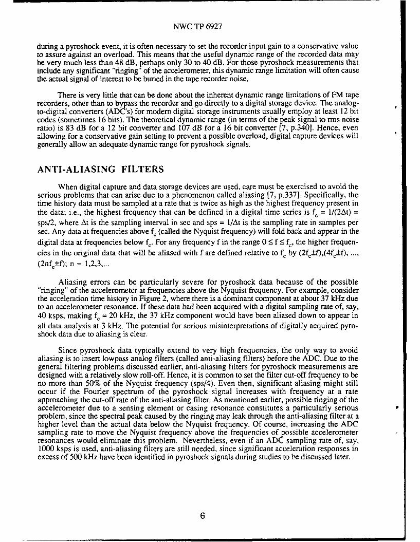
The analysis of pyroshock data is usually accomplished by the calculation of a shockresponse spectrum (SRS) [15-18]. Shock response spectra can be defined for any responseparameter of interest, but absolute acceleration is the most commonly used response parameter forcalculating the SRS of aerospace vehicle pyroshock measurements. Thc acceleration SRS is definedas the maximum acceleration response of a simple mechanical oscillator (single degree-of-freedomsystem) to the measured acceleration time history of the shock, as a function of the resonancefrequency of the oscillator. The mechanical analog of the SRS calculation is illustrated in Figure 4.
There are several SRS values that might be of interest for different applications, namely, the
maximum acceleratio .esponses of the oscillators that occur
(a) during the application of the shock (primary SRS),
(b) after the shock is over (residual SRS),
(c) in the positive direction (positive SRS),
(d) in the negative direction (negative SRS), and
(e) at any time in either direction (maximax SRS).
Each of the noted SRS functions must also be identified with a specific value of damping for theoscillators (usually defined in terms of a damping ratio, C, or a "quality factor", Q = 1/(2 ). Com-monly assumed values of damping for SRS calculations range from zero to 5% of critical. Themaximax SRS with a damping ratio of 5% ( = 0.05) is the quantity used for the U/RGM-109Dpyroshock studies. A typical SRS computed on the Station 18.35 bulkhead during a U/RGM- 109Dpayload cover ejection is shown in Figure 5.
Vf
Frequency, Hz.
FIGURE 4. Illustration Of Shock Response Spectrum Measurement.
7

NWC TP 6927
10 4__
Vp
10
S10
ii
10
1ni l- I I - - I--I--- I
110 1 1
Frequency, Hz
FIGURE 5. Maximax SRS For U/RGM- 109D Payload Cover Ejection Event [211
The theory behind the use of the SRS for shock data analysis is as follows. If a mechanicalcomponent of interest were subjected to the measured shock, the component would respond at allits resonance frequencies that fall in the frequency range of the shock. If it is assumed that eachcomponent resonance produces a linear response with a damping value equal to the damping usedto define the SRS, then the measured SRS identifies the maximum (peak) acceleration response ofthat component at each of its resonance frequencies due to an exposure to that shock. The actualfrequencies of the component resonances do not have to be known, since the SRS yields themaximum acceleration response for any resonance frequency that might exist within the frequencyrange of the analysis. This interpretation makes the SRS a very useful tool for design purposes, aswell as for assessing the equivalence of simulated shocks relative to actual shock environments fortesting purposes.
The concept and application of the SRS is controversial for a number of reasons, includingthe following:
1. The SRS for a given shock is not unique; i.e., there are numerous different transient timehistories that will produce the same SRS.
2. The SRS does not account for the peak acceleration, and hence the damage potential, due to themulti-mode response of a component.
3. The linearity assumption in the SRS is sometimes questionable, particularly for componentssubjected to high intensity, multi-cycle transients like pyroshocks.
4. The SRS is highly sensitive to errors in the assumed damping value for multi-cycle transientslike pyroshocks.
The last problem is the most serious from the viewpoint of pyroshock simulations for testingpurposes. Specifically, the values of the SRS for a single cycle transient (a pulse) can never exceedtwice the peak acceleration of the transient, no matter what damping value is assumed [18].
8
NWC TP 6927
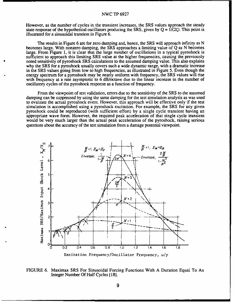
However, as the number of cycles in the transient increases, the SRS values approach the steadystate response of the hypothetical oscillators producing the SRS, given by Q = 1/(2C). This point isillustrated for a sinusoidal transient in Figure 6.
The results in Figure 6 are for zero damping and, hence, the SRS will approach infinity as Nbecomes large. With nonzero damping, the SRS approaches a limiting value of Q as N becomeslarge. From Figure 1, it is clear that the large number of oscillations in a typical pyroshock issufficient to approach this limiting SRS value at the higher frequencies, causing the previouslynoted sensitivity of pyroshock SRS calculations to the assumed damping value. This also explainswhy the SRS for a pyroshock usually covers such a wide dynamic range, with a dramatic increasein the SRS values going from low to high frequencies, as illustrated in Figure 5. Even though theenergy spectrum for a pyroshock may be nearly uniform with frequency, the SRS values will risewith frequency at a rate asymptotic to 6 dB/octave due to the linear increase in the number ofoscillatory cycles of the pyroshock response as a function of frequency.
From the viewpoint of test validation, errors due to the sensitivity of the SRS to the assumeddamping can be suppressed by using the same damping for the test simulation analysis as was usedto evaluate the actual pyroshock event. However, this approach will be effective only if the testsimulation is accomplished using a pyroshock excitation. For example, the SRS for any givenpyroshock could be reproduced (with sufficient effort) by a single cycle transient having anappropriate wave form. However, the required peak acceleration of that single cycle transientwould be very much larger than the actual peak acceleration of the pyroshock, raising seriousquestions about the accuracy of the test simulation from a damage potential viewpoint.
7 7-W < 1, 11=X) P XM =R
X I I % 2fEnvelope, -. el-- N=4 Eveoe
6- P /!r ne p-,
> 1-
5 I
Uo -<
31r
N2 \S3 -t-
2- -
2 -~ N=1
0 0.2 0.4 0.6 0.8 1.0 1.2 1.4 1.6 1.8
Excitation Frequency/Oscillator Frequency, w/p
FIGURE 6. Maximax SRS For Sinusoidal Forcing Functions With A Duration Equal To AnInteger Number Of Half Cycles [ 18].
9
NWC TP 6927
Before closing the background discussions of data analysis, it should be mentioned that thereare other techniques for analyzing and evaluating transient data, including pyroshock data. The twomost common alternatives are the Fourier spectrum [16] and the energy spectrum [7, p.477], whichis simply the square of the magnitude of the Fourier spectrum. These two functions provide adescription of the transient environment itself, rather than the effect of the environment on ahypothetical component. They also yield rigorous input/output relationships that are not providedby the SRS. Such analysis procedures have been explored for the evaluation of pyrotechnic andballistic shocks [ 19], but have been found lacking for these applications in at least two ways. First,Fourier and energy spectra do not define peak accelerations for either the environment or acomponent subjected to the environment. Hence, they are not directly indicative of the damagepotential of the environment. Second, the estimation of both functions for statistical events likepyroshocks involves large random errors that cannot be adequately suppressed without a severelimitation on the spectral resolution of the analysis.
TESTS AND EXPERIMENTAL STUDIES
Following the DT-5 flight failure, various pyroshock tests and experimental studies wereinitiated and performed by the major participants in the U/RGM-109D program. The detailed resultsof these tests and experiments have been or will be published by the responsible organizations, andneed not be covered here. However, as further background for the recommendations concerningpyroshock measurement procedures, it is desirable to review the purpose of the principal tests andexperiments, and the general manner in which they were executed.
GDC BACKYARD TESTS
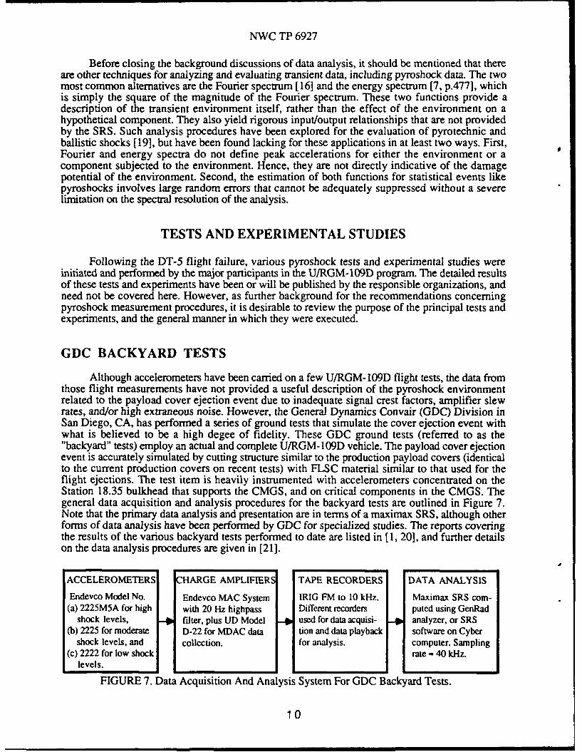
Although accelerometers have been carried on a few U/RGM- 109D flight tests, the data fromthose flight measurements have not provided a useful description of the pyroshock environmentrelated to the payload cover ejection event due to inadequate signal crest factors, amplifier slewrates, and/or high extraneous noise. However, the General Dynamics Convair (GDC) Division inSan Diego, CA, has performed a series of ground tests that simulate the cover ejection event withwhat is believed to be a high degee of fidelity. These GDC ground tests (referred to as the"backyard" tests) employ an actual and complete U/RGM-109D vehicle. The payload cover ejectionevent is accurately simulated by cutting structure similar to the production payload covers (identicalto the current production covers on recent tests) with FLSC material similar to that used for theflight ejections. The test item is heavily instrumented with accelerometers concentrated on theStation 18.35 bulkhead that supports the CMGS, and on critical components in the CMGS. Thegeneral data acquisition and analysis procedures for the backyard tests are outlined in Figure 7.Note that the primary data analysis and presentation are in terms of a maximax SRS, although otherforms of data analysis have been performed by GDC for specialized studies. The reports coveringthe results of the various backyard tests performed to date are listed in [1, 20], and further detailson the data analysis procedures are given in [21].
ACCELEROMETERS HARGE AMPLIFIER TAPE RECORDERS DATA ANALYSIS
Endevco Model No. Endevco MAC System IRIG FM to 10 kHz. Maximax SRS corn-(a) 2225M5A for high with 20 Hz highpass Different recorders puted using GenRad
shock levels, fdter, plus UD Model used for data acquisi- analyzer, or SRS(b) 2225 for moderate D-22 for MDAC data tion and data playback software on Cyber
shock levels, and collection, for analysis. computer. Sampling(c) 2222 for low shock rate - 40 kHz.
levels.
FIGURE 7. Data Acquisition And Analysis System For GDC Backyard Tests.
10

NWC TP 6927
The GDC backyard tests provide the basic description of the dynamic loads due to theU/RGM-109D payload cover ejection event and, hence, the definition of qualification test levels forCMGS components. However, because of the relatively high cost associated with conducting thesetests, they have not been used for detailed investigations of the DT-5 flight failure mechanism or theruggedness of the CMGS components.
MDAC WELDED BODY STRUCTURE TESTS
McDonnell Douglas Astronautics Company (MDAC) in St. Louis, MO, participated in theGDC backyard tests in that most of the pryoshock data collected on the CMGC components duringthese tests were independently analyzed by MDAC. These data were used by MDAC to produce aqualification test report for the CMGS [22]. Beyond this activity, MDAC has been pursuing CMGScomponent ruggedness studies using a special test article consisting of a welded body strm.cture,referred to by MDAC as the extended tube forward body section. The original test article simulatedthe geometry and basic material properties of the U/RGM-109D vehicle, but had no simulation ofthe engine, wings, payload covers, payload, or accessory equipment, except for the CMGS and theDigital Scene Matching Area Calculator (DSMAC) processor unit. Later in the experimental studies,a missile aft body section (without an engine) and mass simulations of payload bay equipment wereadded to the welded body structure. The test article also has grooves for the payload cover jettisoncharges (FLSC) in the missile body structure, rather than in the covers as for the actual vehicle.
The MDAC test article is used to simulate the pyroshock loads on the CMGS componentsdue to the U/RGM- 109D payload cover ejection event by igniting a string of mild detonation cordmounted on the outside of the body structure. Payload covers are not jettisoned and no material iscut. Hence, the tests do not provide a fully accurate simulation of the cover ejection event. Aconsiderable effort has been made by MDAC to "tune" the test article so as to generate SRS data inthe region of the CMGS that are similar to the SRS results from the GDC backyard tests. Althoughnot in perfect agreement, the SRS data now produced by the MDAC test article are sufficientlysimilar to the backyard test data to allow the MDAC test article to be used as an effective, low costtest bed for pyroshock studies of the CMGS components. In particular, the MDAC test article hasbeen used extensively to study shock margins and shock induced failures of CMGS components insupport of the DT-5 flight failure investigation. These studies are ongoing, and the results at thistime have not been published.
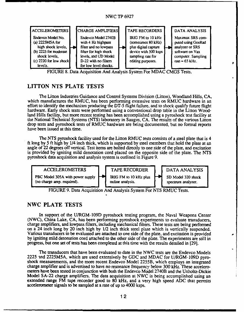
The data acquisition and analysis system used for the MDAC test article experiments is out-lined in Figure 8. Note that the system is similar to that used for the backyard tests in Figure 7, inparticular, the same types of accelerometers are employed. Due to the basic problems associatedwith accelerometer measurements of pyroshocks discussed in the Background section, it w.sdetermined early in the program that comparisons of data from different experiments would begreatly facilitated by using the same types of accelerometers. It is also seen in Figure 8 that MDACdoes not use lowpass filters in their charge amplifiers as GDC does. MDAC avoids chargeamplifier lowpass filters because of the problems revealed by the pyroshock instrumentation studiesdetailed in [9]. However, MDAC does use anti-aliasing filters prior to digitizing the data foranalysis. MDAC has not published a detailed description of their pyroshock instrumentationsystem, but some additional details are available from [23], which presents an independentevaluation and critique of the system.
Beyond the pyroshock testing activities directly related to the U/RGM-109D payload coverejection problem, MDAC-West, Huntington Beach, CA, has been performing extensive, publishedstudies of the simulation and measurement of pyroshock events involving FLSC excitations [9, 12,24-28]. The results of these general studies have clearly impacted decisions concerning testingprocedures and instrumentation during the U/RGM-109D related pyroshock tests. Hence, theMDAC-West experience should be considered part of the body of knowledge that influenced thetesting by MDAC-St. Louis, and probably the testing by others as well.
11
NWC TP 6927
ACCELEROMETERS CHARGE AMPLIFIERS TAPE RECORDERS DATA ANALYSIS
Endevco Model No. Endevco Model 2740B IRIG FM to 10 kHz Maximax SRS corn-(a) 2225MSA for with 4 Hz highpass (sometimes 80 kHz) puted using GenRad
high shock levels, -- filter and no lowpass plus digital capture analyzer or SRS(b) 2225 for moderate filter for high shock device with 500 ksps software on Vax
shock levels, levels, and UD Model sampling rate for computer. Sampling(c) 2220 for low shock D-22 with no filters editing purposes. rate - 65 kHz.
levels, for low level shocks.
FIGURE 8. Data Acquisition And Analysis System For MDAC CMGS Tests.
LITTON NTS PLATE TESTS
The Litton Industries Guidance and Control Systems Division (Litton), Woodland Hills, CA,which manufactures the RMUC, has been performing extensive tests on RMUC hardware in aneffort to identify the mechanism producing the DT-5 flight failure, and to shock qualify future flighthardware. Early shock tests were performed using a conventional drop table in the Litton Wood-land Hills facility, but more recent testing has been accomplished using a pyroshock test facility atthe National Technical Systems (NTS) laboratory in Saugus, CA. The results of the various Littondrop tests and pyroshock tests of RMUC hardware are being documented, but no formal reportshave been issued at this time.
The NTS pyroshock facility used for the Litton RMUC tests consists of a steel plate that is 4ft long by 5 ft high by 1/4 inch thick, which is supported by steel members that hold the plate at anangle of 22 degrees off vertical. Test items are bolted directly to one side of the plate, and excitationis provided by igniting mild denotation cord placed on the opposite side of the plate. The NTSpyroshock data acquisition and analysis system is outlined in Figure 9.
ACCELEROMETERS TAPE RECORDER DATA ANALYSIS
PBC Model 305A with power supply IRIG FM to 10 kHz plus SD Model 320 shock(no charge amp. required). online analysis. spectrum analyzer.
FIGURE 9. Data Acquisition And Analysis System For NTS RMUC Tests.
NWC PLATE TESTS
In support of the U/RGM-109D pyroshock testing program, the Naval Weapons Center(NWC), China Lake, CA, has been performing pyroshock experiments to evaluate transducers,charge amplifiers, and lowpass filters, including mechanical filters. These tests are being performedon a 24 inch long by 20 inch high by 1/2 inch thick steel plate which is vertically suspended.Various transducers to be evaluated are attached to one side of the plate, and excitation is providedby igniting mild detonation cord attached to the other side of the plate. The experiments are still inprogress, but one set of tests has been completed at this time with the results detailed in [291.
The transducers that have been evaluated to date in the NWC tests are the Endevco Models2225 'md 2225M5A, which are used extensively by GDC and MDAC for U/RGM-109D pyro-shock measurements, and the more recent Endevco Model 2255B, which employs an integratedcharge amplifier and is advertised to have no resonance frequency below 300 kHz. These accelero-meters have been tested in conjunction with both the Endevco Model 2740B and the Unholtz-DickieModel SA-22 charge amplifiers. The data acquisition at NWC is being accomplished using anextended range FM tape recorder good to 80 kHz, and a very high speed ADC that permitsaccelerometer signals to be sampled at a rate of up to 4000 ksps.
12

NWC TP 6927
By using the very high sampling rates, the NWC experiments produced some revealing data.In particular, the measurements provided a clear indication of the theoretical "pre-shock" caused bythe near instantaneous velocity change induced by pyroshock events [4]. This is illustrated inFigure 10, which shows the first 0.45 msec of a typical time history measured by an EndevcoModel 2255B accelerometer located 2 inches from a 2.5 grain/ft pyroshock source. The data weresampled at a rate of 4000 ksps, providing an upper frequency limit of 2000 kHz. Note that there isan initial acceleration pulse with an indicated magnitude of about 80,000 g for this relatively modestpyrotechnic event.
Other significant results of the NWC pyroshock experiments performed to date are as follows:
1. The Endevco Model 2225M5A accelerometer commonly revealed a resonant response at both acasing resonance frequency of about 35-40 kHz, and a crystal resonance frequency of about82-94 kHz.
2. The Endevco Model 2255B accelerometer sometimes revealed a resonant response, eventhough its lowest resonance frequency is near 300 kHz. This supports the conclusion that it isnot feasible to build an accelerometer that can measure structural responses near a pyroshockexcitation without possible ringing.
3. Both the Endevco and the Unholtz-Dickie charge amplifiers (used with an Endevco Model2225M5A accelerometer) produced inconsistent and often clearly spurious signals when theirelectronic lowpass filters were in the circuit. However, the Endevco amplifiers appeared, onbalance, to provide slightly more consistent data.
In summary, the results of the NWC experiments to date [29] have tended to confirm thebasic results of the earlier MDAC-West experiments [9], namely, piezoelectric accelerometers com-monly resonate when making pyroshock measurements near the source, and the electronic lowpassfilters used in shock measurement charge amplifiers do not appear to be effective in suppressingthis spurious portion of the signal. The reason for this malfunction of the charge amplifier lowpassfilters is not understood at this time. However, NWC plans to continue these investigations, as wellas to pursue further studies of mechanical lowpass filters, which theoretically should resolve theproblem. In the meantime, the results of pyroshock measurements with electronic filters having alowpass cut-off below about 20 kHz must be considered suspect.
4x10⁴
'-
0>
0
1- -4x10⁻⁴
-4x
-8x10 I I0 0.1 0.2 0.3 0.4
Time, msec
FIGURE 10. Pyroshock Acceleration Time History Showing Pre-Shock Event.
13

NWC TP 6927
NWC STANDARD TAPE
Following some of the pyroshock tests performed by the participants in the U/RGM- 109Dpayload cover ejection studies, problems occurred when the data recorded on one tape recorderwere played back on a different tape recorder with similar specifications. These problems motivatedNWC, Code 3665, to create a "Standard Tape". Copies of this Standard Tape have been providedto the primary U/RGM-109D contractors.
The NWC Standard Tape is not a NBS quality tape; such tapes are usually made on specialmachines with heads that record across the full width of the tape. The NWC tape was made on aconventional Ampex FR-3010 tape recorder running under tachometer control after being adjustedby factory technicians to be as perfect as feasible. When used properly, the Standard Tape providesa direct way of adjusting the azimuth, speed, and tracking of other tape recorders. The use of theStandard Tape by the different facilities analyzing U/RGM-109D should eliminate potential recorderinduced data quality problems, and insure that a tape recording made at one facility will be playableat all other facilities. Of course, the IRIG standards are supposed to insure this, but a recorderadjusted at one edge of the IRIG standard may not be able to play tapes made on another recorderadjusted at the opposite edge of the standard.
The NWC Standard Tape is a mime of the classical azimuth and speed tape, where a 10% ofband edge (wideband 2) signal was recorded simultaneously on all tracks. 'I he recording was madesuch that the third harmonic was 40 dB down from the fundamental, and the recorder was adjustedin the standard manner such that a 1 volt rms input gives a 1 volt rms output. The tape is an originalthat could be used as a "set level" tape, but the real purpose of the tape is to verify the speed,azimuth, and tracking performance of other tape recorders.
To use the Standard Tape to verify another tape recorder, the following tests are recom-mended.
Azimuth. NWC measured the variance between the even and odd heads on the Ampex taperecorder to be 2.5 microsec, which means that a 1.5 inch adjustment is accurate to .000125 inch.When the azimuth is aligned such that the delay is constant between the even and odd reproduceheads, and there is no variance across a given reproduce head, the reproduce heads on the recorderbeing checked are parallel to the record heads on the NWC recorder. A relative measure of howclose the record heads are to the NWC recorder can then be made simply by recording a similarsignal on a scratch tape, and measuring how much variance there is across the reproduce heads. IfNWC made a dub of a test tape, the azimuth error would be at its minimum if the azimuth on theplayback recorder is adjusted with the Standard Tape in the above manner.
Speed Accuracy. At 120 inch/sec, the recorded signal should be 50 kHz. If the playbackrecorder varies by more than ± 200 Hz (±0.4%) from this frequency, the speed probably requiresan adjustment.
Tracking. The Ampex technicians measured the physical placement of the tracks on theStandard Tape by recording a short burst of data, cutting off a piece of tape, and developing thetape with an iron based solution so that the magnetized portion of the tape was visible. The samplewas examined by an NWC technician with a jeweler's loupe equipped with a calibrated scale. Itwas confirmed that the tracks were exactly where they should be. A similar experiment can be doneby any contractor if an azimuth adjustment yields marginal improvement of R tatw recorded onanother machine. A check can be made with the Standard Tape, as follows. If the azimuth cannotbe adjusted (an intermediate band tape machine has no azimuth adjustment), or the tape will notplay back easily, a tracking problem may exist. If the NWC Standard Tape plays well on a play-back recorder after the azimuth is adjusted, but when a recording is made, the tape reproducespoorly, then a tracking or record head alignment problem could be indicated.
14

NWC TP 6927
Exact specifications for the Ampex FR-3010 tape recorder and further information on theStandard Tape are available from the Naval Weapons Center, Code 3665, China Lake, CA.
RECOMMENDED PROCEDURES
The pyroshock data from the various tests and experiments summarized in the previoussection have been presented during a series of U/RGM-109D Technical Interchange Meetings(TIM's) held primarily at GDC in San Diego, CA (occasional TIM's have been held at GDC inWashington, D.C., MDAC in San Diego, CA, or NTS in Saugus, CA). During TIM No. 9 held on9 July 1987, an action item was generated to form a "Shock Analysis Working Group" (SAWG)composed of appropriate personnel from NWC, GDC, MDAC, Litton, the Applied PhysicsLaboratory (APL), and Astron Research and Engineering (Astron). Tlhc originally stated purpose ofthe SAWG was to (a) make a determination of the validity of the U/RGM-109D pyroshock test dataproduced by the GDC backyard tests, and (b) arrive at a validated SRS that could be used to derivea shock specification for the CMGS. The SAWG was formed and held its first meeting on 9 July1987, under the chairmanship of G.C. McKinnis of GDC. Three additional meetings of the SAWGwere held on 20 July, 5 August, and 10 September 1987, at either GDC or MDAC, San Diego,CA. Beyond the original objectives of the SAWG, the meetings produced a series of agreements onhow the pyroshock data associated with the U/RGM-109D program should be acquired, analyzed,and presented. An excellent summary of many of the conclusions of the SAWG are documented byGDC and MDAC in [211. Based upon the results of the SAWG meetings, and other evaluations byNWC, the more important conclusions concerning the U/RGM-109D shock data, and the basicreasons behind them, are now summarized. It should be understood that the SAWG is stillfunctioning and, hence, additional or modified conclusions and agreements may be forthcoming inthe future.
TRANSDUCERS
Accelerometer Types. It was concluded at an early TIM that the principal participants inthe U/RGM-109D program should make all pyroshock measurements using similar accelerometersfrom one test to another, as follows:
1. Endevco Model 2225M5A should be used for the highest level shock measurements (on theStation 18.35 bulkhead).
2. Endevco Model 2225 accelerometers should be used for the intermediate level shock measure-ments (on the base of CMGS components).
3. Endevco Model 2220 accelerometers should be used for the lowest level shock measurements(on elememts inside CMGS components).
It should be emphasized that the reason for this conclusion is not based upon a consensus that theseaccelerometers are the best available for pyroshock measurements. They were simply theaccelerometers first used to acquire U/RGM-109D pyroshock data. It follows that their continueduse is desirable to suppress possible data variations due to artifacts of the accelerometer perform-ance and, thus, enhance the comparability of data from one test to another, as well as between GDCand MDAC tests. It should be mentioned that Litton did not use these specific accelerometers fortheir flat plate pyroshock tests at NTS.
Electrical Isolation. The accelerometers being used for the U/RGM-109D pyroshockmeasurements are older models that are not electrically insulated. Hence, great care must beexercised to avoid noise problems due to ground loops and the electromagnetic radiation (EMR)pulse generated by the FLSC ignition. Recommended actions include the following:
15
NWC TP 6927
1. The accelerometers must be mounted to the test structure through electrically isolated studs, orwith a glue that provides adequate electrical insulation.
2. All accelerometers must be checked with an ohmmeter for possible grounding to the teststructure before each test (the only ground should be at the charge amplifier).
3. All wiring between the accelerometers and their charge amplifiers must be noise-treated coaxialcable (no twisted pairs).
Both GDC and MDAC checked for possible EMR contamination of accelerometer signals duringearly pyroshock tests by hanging an extra accelerometer near the test structure, and wiring it to acharge amplifier exactly like the measurement accelerometers. A significant output from the freeaccelerometer due to the pyroshock event would have indicated an EMR noise interferenceproblem.
Accelerometer Mountings. Where mounting blocks are needed to attach the accelero-meters to the test structure, the following actions are recommended to avoid mounting blockresonance and separation problems.
1. The mounting blocks should be aluminum with no dimension greater than 1 inch on a side. Thiswill assure a resonance frequency of the mounting block, loaded with the accelerometer, inexcess of 40 kHz.
2. The mounting blocks should be both glued and bolted to the test structure to reduce the risk ofseparation during the pyroshock.
3. Following each test, the bolts holding the mounting blocks to the test structure should beloosened to determine if the block is still bonded to the structure by the glue. A broken gluebond would indicate the mounting block separated during the pyroshock.
SIGNAL CONDITIONING AND RECORDING
Charge Amplifiers. Both GDC and MDAC generally use either the Endevco MACsystem or Endevco Model 2740B charge amplifiers for acquisition of the more intense pyroshocksignals, and the Unholtz-Dickie Model UD-22 charge amplifers for the lower level pyroshocksignals. A continuation of this practice is recommended, since the results of experimental studies byNWC 129] as well as MDAC experience indicate the Endevco charge amplifiers may produceslightly better results for intense shock signals.
Electronic Lowpass Filters. It has been concluded from the results in [9, 29] thatelectronic lowpass filtering in the charge amplifiers with a cut-off frequency of less than 20 kHzshould not be used. Even though a 2 kHz lowpass filter would allow SRS calculations with greatlyenhanced signal-to-noise ratios, there is strong evidence that sach filtering will produce inconsistentSRS results, at least for the more intense pyroshocks.
Mechanical Lowpass Filters. The use of mechanical lowpass filters is not recom-mended at this time, since no mechanical filter has yet been verified to be effective for the pyro-shock signals and accelerometers currently being used for the U/RGM-109D measurements.
Electronic Highpass Filters. There is no objection to electronic highpass filtering in thecharge amplifiers with a cut-off frequency of 20 Hz or less, since there is no evidence that suchhigh pass filtering causes erroneous data.
16
NWC TP 6927
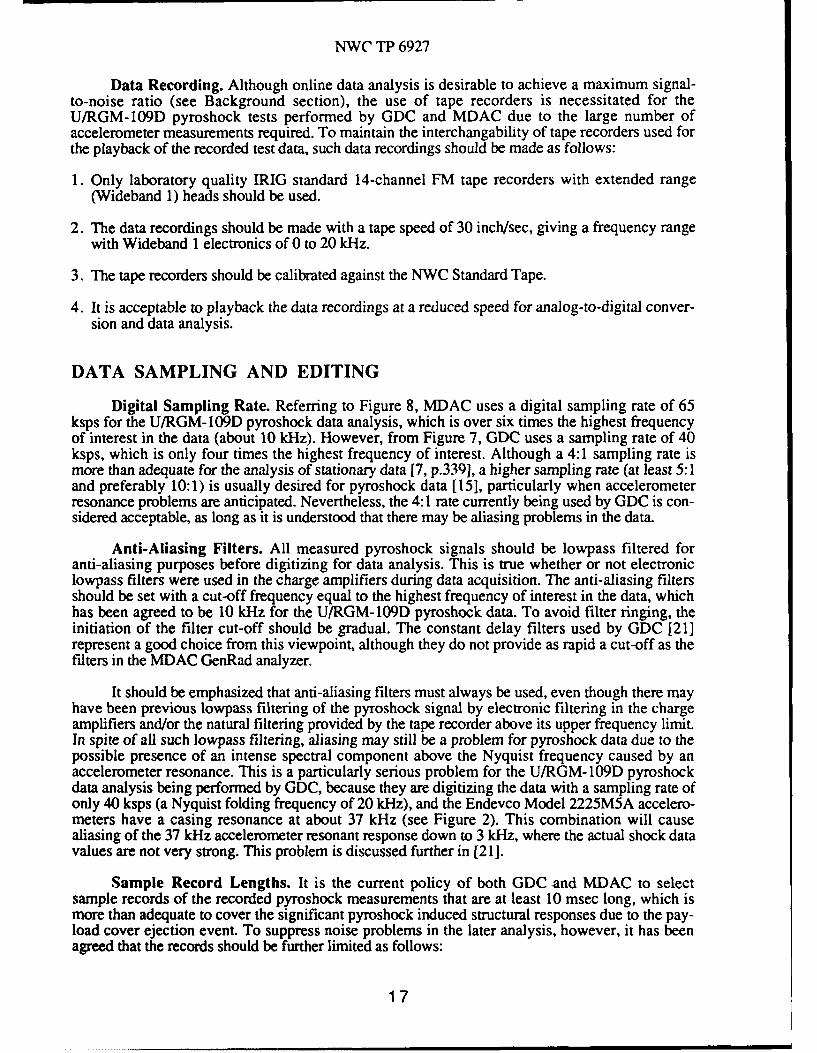
Data Recording. Although online data analysis is desirable to achieve a maximum signal-to-noise ratio (see Background section), the use of tape recorders is necessitated for theU/RGM- 109D pyroshock tests performed by GDC and MDAC due to the large number ofaccelerometer measurements required. To maintain the interchangability of tape recorders used forthe playback of the recorded test data, such data recordings should be made as follows:
1. Only laboratory quality IRIG standard 14-channel FM tape recorders with extended range(Wideband 1) heads should be used.
2. The data recordings should be made with a tape speed of 30 inch/sec, giving a frequency range
with Wideband 1 electronics of 0 to 20 kHz.
3. The tape recorders should be calibrated against the NWC Standard Tape.
4. It is acceptable to playback the data recordings at a reduced speed for analog-to-digital conver-sion and data analysis.
DATA SAMPLING AND EDITING
Digital Sampling Rate. Referring to Figure 8, MDAC uses a digital sampling rate of 65ksps for the U/RGM-109D pyroshock data analysis, which is over six times the highest frequencyof interest in the data (about 10 kHz). However, from Figure 7, GDC uses a sampling rate of 40ksps, which is only four times the highest frequency of interest. Although a 4:1 sampling rate ismore than adequate for the analysis of stationary data [7, p.33 9 ], a higher sampling rate (at least 5:1and preferably 10:1) is usually desired for pyroshock data [15], particularly when accelerometerresonance problems are anticipated. Nevertheless, the 4:1 rate currently being used by GDC is con-sidered acceptable, as long as it is understood that there may be aliasing problems in the data.
Anti-Aliasing Filters. All measured pyroshock signals should be lowpass filtered foranti-aliasing purposes before digitizing for data analysis. This is true whether or not electroniclowpass filters were used in the charge amplifiers during data acquisition. The anti-aliasing filtersshould be set with a cut-off frequency equal to the highest frequency of interest in the data, whichhas been agreed to be 10 kHz for the U/RGM- 109D pyroshock data. To avoid filter ringing, theinitiation of the filter cut-off should be gradual. The constant delay filters used by GDC [21]represent a good choice from this viewpoint, although they do not provide as rapid a cut-off as thefilters in the MDAC GenRad analyzer.
It should be emphasized that anti-aliasing filters must always be used, even though there mayhave been previous lowpass filtering of the pyroshock signal by electronic filtering in the chargeamplifiers and/or the natural filtering provided by the tape recorder above its upper frequency limit.In spite of all such lowpass filtering, aliasing may still be a problem for pyroshock data due to thepossible presence of an intense spectral component above the Nyquist frequency caused by anaccelerometer resonance. This is a particularly serious problem for the U/RGM- 109D pyroshockdata analysis being performed by GDC, because they are digitizing the data with a sampling rate ofonly 40 ksps (a Nyquist folding frequency of 20 kHz), and the Endevco Model 2225M5A accelero-meters have a casing resonance at about 37 kHz (see Figure 2). This combination will causealiasing of the 37 kHz accelerometer resonant response down to 3 kHz, where the actual shock datavalues are not very strong. This problem is discussed further in [211.
Sample Record Lengths. It is the current policy of both GDC and MDAC to selectsample records of the recorded pyroshock measurements that are at least 10 msec long, which ismore than adequate to cover the significant pyroshock induced structural responses due to the pay-load cover ejection event. To suppress noise problems in the later analysis, however, it has beenagreed that the records should be further limited as follows:
17
NWC TP 6927
1. The data prior to the initiation of the acceleration response should be deleted (the sample recordfor analysis should start at the exact beginning of the acceleration transient).
2. The data after the acceleration transient has clearly diminished into the instrumentation noisefloor should also be deleted.
The latter recommended action requires judgment that should always be conservative; i.e., it isbetter to make the record too long than too short, since an excessive truncation of the accelerationsignal may distort the analysis results more severely than additional noise.
Data Editing. All digitized pyroshock data records should be carefully inspected for errorsprior to data reduction by an experienced analyst. This should include a visual inspection for thefollowing common anomalies:
1. Obvious wild points, dropouts, magnitude limitations, or other anomalies that are clearly
indicative of an ADC malfunction or clipping.
2. Signal terminations indicative of an accelerometer failing or coming off the test structure.
3. Sharp, randomly occurring spikes in the signal indicative of noise due to a loose connector orother intermittent noise sources.
4. Single peaks, zero shifts, or other indications of saturation in the accelerometer, charge amp-lifier, and/or tape recorder (see [9, 21, 291 for illustrations).
Velocity Validation. Beyond the above visual checks of the data by an experiencedanalyst, it has been agreed that all U/RGM-109D pyroshock test data should be further checked byan integration to a velocity signal. A clean, accurate pyroshock acceleration signal should integrateto a velocity signal that looks very much like the acceleration signal. If the velocity signal reveals arapid shift in its mean value, particularly during the early part of the transient where the shockmagnitude is intense, this is indicative of a defect in the acceleration measurement. Excellent illus-trations are presented in [21]. In applying the velocity data validation procedure, it should be notedthat a low frequency trend (usually one or fewer cycles over the record length) can be expected inthe integration of any signal, due to the integration of low frequency noise in the data (often called aWiener process). Care must be exercised to distinguish between the more rapid trends indicative ofa spurious acceleration signal, and the slower trends due to a normal integrated noise problem.
DATA ANALYSIS
Type of Analysis. The U/RGM-109D pyroshock data have been, and should continue tobe, analyzed in terms of shock response spectra (SRS) with a 5% damping ratio (Q = 10).Although the SRS is a controversial data analysis procedure that is vulnerable to misinterpretations,particularly for pyroshock data, it is nevertheless considered to provide the most useful descriptionof shock data from the viewpoint of establishing design criteria and test specifications. Other formsof data analysis, primarily Fourier and energy spectra, have been used very effectively forspecialized data studies by GDC [21] and NWC [29], but the SRS with 5% damping is agreed tobe the proper U/RGM- 109D pyroshock data analysis procedure for general applications.
Initial Conditions. The results of an SRS calculation can be significantly influenced bythe initial conditions assumed for the data. It has been agreed that all U/RGM-109D pyroshock datarecords should be forced to yield a net velocity change of zero from the beginning to the end of thetransient event (called the AV = 0 criterion) before the SRS calculation is performed. The AV = 0condition is achieved by calculating the average value of the acceleration time history record, andsubtracting this average from all data values.
18

NWC TP 6927
Background Noise. Due to the low sensitivity of some of the shock accelerometers usedfor the U/RGM-109D pyroshock measurements, and other factors limiting the dynamic range of themeasurements (see Background section), the pyroshock acceleration data records often includesubstantial background noise. The effects of this noise on the SRS analysis -an be suppressedsomewhat by a judicious selection of the record length, as detailed earlier. However, the noisesuperimposed on the transient signal may still influence the SRS calculation, particularly at thelower frequencies where the actual shock signal is not very intense.
It has been agreed that all U/RGM-109D pyroshock test data should be checked for thepossible influence of background noise by calculating a "noise" SRS from a segment of each mea-sured acceleration record preceding the transient. The length of the data segment used to calculatethe noise SRS shou!d be identical to the record length used to calculate the actual pyroshock SRS.If there appears to be a change in the background noise on the record from before to after thetransient, the procedure should be repeated for a segment of the data record after the transient aswell. For the more intense shock measurements, the noise SRS will often approach the pyroshockSRS at the lower frequencies and, hence, limit the accuracy of the low frequency SRS values.
SRS Frequency Range. If the acceleration time history records pass all the editingchecks reviewed earlier, there is no reason to question the validity of the resulting SRS calculationsat the higher frequencies (2 to 10 kHz). However, it has been agreed that the lower frequency limitfor valid data should be established on a case by case basis using the following criteria.
1. The SRS results should be considered invalid at frequencies below that fr.quency where thenoise SRS is less than 6 dB below the pyroshock SRS.
2. A slope in the SRS values of 6 dB/octave below 100 Hz is indicative of good data.
3. In any case, SRS values should not be displayed at frequencies below 100 Hz.
REFERENCES
1. McKinnis, C., and Markle, B.,"U/RGM-109D Payload Cover Separation Test Summary andData Directory", Memorandum No. D-87-065-CM, General Dynamics Convair Division, SanDiego, CA, 30 October 1987. UNCLASSIFIED.
2. Kalbfleisch, K.C., "Review Of Pyro-Shock Generating Devices And Source Levels",Proceedings, Institute of Environmental Sciences, Pyrotechnic Shock Tutorial Session, 1985.UNCLASSIFIED.
3. Walton, W.S., "Shock Measurement During Ballistic Impact Into Armored Vehicles", Shockand Vibration Bulletin No. 50, Part 2, pp. 45-55, 1980. UNCLASSIFIED.
4. Galef, A.E., "The Pre-Pulse In Pyroshock Measurement And Analysis", Shock and VibrationBulletin No. 56, Part 3, pp. 29-32, 1986. UNCLASSIFIED.
5. Cremer, L., Heckl, M., and Ungar, E.E., Structure-Borne Sound, Springer-Verlag, NewYork, 1973.
6. Dranetz, A.I., and Orlacchio, A.W., "Piezoelectric And Piezoresistive Pickups", Chapter 16,Shock And Vibration Handbook, 2nd edition, McGraw-Hill, New York, 1976.
7. Bendat, J.S., and Piersol, A.G., RANDOM DATA: Analysis And Measurement Procedures,2nd edition, Wiley, New York, 1986.
19
NWC TP 6927
8. Bendat, J.S., and Piersol, A.G., Engineering Applications Of Correlation and Spectral Anal-ysis, pp. 13-15, Wiley, New York, 1980.
9. Powers, D.R., "Charge Amplifier Characteristics When Subjected To Pyrotechnic Shock",Report No. TM-TMHK-ENV-R7484, McDonnell Douglas Astronautics Company, Hunting-ton Beach, CA, 14 January 1987. UNCLASSIFIED.
10. Wilson, J.S., "Accelerometers For Pyroshock Measurements", Proceedings, Institute ofEnvironmental Sciences, pp. 263-267, 1986. UNCLASSIFIED.
11. Sill, R.D., and Leonhardt, P.M., "Instrumentation For Measuring Pyroshock", Proceedings,Institute of Environmental Sciences, Pyrotechnic Shock Tutorial Session, 1985. UNCLAS-SIFIED.
12. Powers, D.R., "Development Of A Pyrotechnic Shock Test Facility", Shock And VibrationBulletin No. 44, Part 3, pp. 73-82, 1974. UNCLASSIFIED.
13. Broch, J.T., Mechanical Vibration And Shock Measurements, 2nd edition, Bruel & Kjaer,Naerum, Denmark, 1980.
14. Beauchamp, K.G., and Yuen, C.K., Data Acquisition For Signal Analysis, George Allen &Unwin, London, 1980.
15. Curtis, A.J., "Shock Data Acquisition And Analysis In The Laboratory", Proceedings,Institute of Environmental Sciences, Pyrotechnic Shock Tutorial Session, 1985. UNCLAS-SIFIED.
16. Rubin, S., "Concepts In Shock Data Analysis", Chapter 23, Shock And Vibration Handbook,2nd edition, McGraw-Hill, New York, 1976.
17. Kelly, R.D., and Richman, G., Principles And Techniques Of Shock Data Analysis, SVM-5,Shock and Vibration Information Center, NRL, Washington, D.C., 1969.
18. Jocobsen, L.S., and Ayre, R.S., Engineering Vibrations, McGraw-Hill, New York, 1958.
19. Piersol, A.G., "Evaluation Of The Harpoon Missile Shock Environment During EjectionLaunch By Aircraft Launchers", TP-5880, Naval Weapons Center, China Lake, CA, January1977. UNCLASSIFIED.
20. anon, "Submunition Land-Attack Tomahawk Test Report For Shock Reduction TestProgram", Report No. SDP-2401, GDC-AUR-87-135, General Dynamics Convair Division,San Diego, CA, January 1988. UNCLASSIFIED.
21. Bereit, N., et al, "Data Reduction Procedure And Problem Resolution For The U/RGM- 109DPayload Cover Separation Tests", Memorandum No. D-87-067-CM, General DynamicsConvair Division, San Diego, CA, 10 November 1987. UNCLASSIFIED.
22. Makarsky, J.A., "BGM- 109D Cruise Missile Guidance Set Pyrotechnic Shock QualificationTest Report", Report No. TMHK-26782, McDonnell Douglas Astronautics Company, St.Louis, MO, 25 October 1987. UNCLASSIFIED.
23. Piersol, A.G., "Review of Planned Shock Margin Tests For U/RGM-109D CMGS", ReportNo. 7117-01, Astron Research and Engineering, Santa Monica, CA, March 1987. UNCLAS-SIFIED.
20
NWC TP 6927
24. Powers, D.R., "Simulation Of Pyrotechnic Shock In A Test Laboratory", Proceedings,Institute of Environmental Sciences, pp. 5-9, April 1976. UNCLASSIFIED.
25. Powers, D.R., "Strain Histories Associated With Stage Separation Systems Using LinearShaped Charge", Shock and Vibration Bulletin No. 53, Part 1, pp. 89-96, May 1983.UNCLASSIFIED.
26. Powers, D.R., Wright, C.E., and Jones, W.N., "Harpoon Pyrotechnic Shock Study"TP-6133, Naval Weapons Center, China Lake, CA, September 1979. UNCLASSIFIED.
27. Powers, D.R., "Pyroshock Test Simulation Methods", Proceedings, Institute of Environ-mental Sciences, Pyrotechnic Shock Tutorial Session, 1985. UNCLASSIFIED.
28. Powers, D.R., "Summary Of Testing Techniques", Shock and Vibration Bulletin 56, Part 3,pp. 135-142, August 1986. UNCLASSIFIED.
29. Veit, B.R., "Accelerometer and Shock Amplifier Evaluation Test Report", (to be published asReg Memo to H.R. Blecha), Naval Weapons Center, China Lake, CA, 1987. UNCLAS-SIFIED.
21

IffrrIAL DISMU)TIOE
4 Naval Air System CommandAIR-5004 (2)AIR-505 (2)
1 Chief of Naval Research (Technical Library)2 Naval Sea Systems Command (SEA-09B312)1 Coiatder in Chief, U. S. Pacific Fleet, Pearl Harbor (Code 325)1 Colander, Third Fleet, San Francisco1 Commander, Seventh Fleet, San Francisco2 Naval Academy, Annapolis (Director of Research)1 Naval Air Development Center, Warminster (Technical Library)1 Naval Avionics Center, Indianapolis (Technical Library)1 Naval Ocean Systems Center, San Diego1 Naval Ordnance Station, Indian Head (Technical Library)1 Naval Postgraduate School, Monterey1 Naval Research Laboratory (Technical Library)1 Naval Strike Warfare, Fallon (Intelligence Library)4 Naval Surface Weapons Center, Dahlgren
Technical Library (1)3 Naval Surface Weapons Center, White Oak Laboratory, Silver Spring
Technical Library (1)1 Naval War College, Newport1 Naval Weapons Support Center, Crane (Technical Library)7 Pacific Missile Test Center, Point Mugu
Technical Library (1)1 Aberdeen Proving Ground (Technical Library)1 Army Armament Research, Development and Engineering Center, Dover (Technical Library)1 Harry Diamond Laboratories, Adelphi (Technical Library)1 Headquarters, U. S. Air Force (Deputy Chief of Staff, Research and Development)1 Air Force Armament Division, Fglin Air Force Base (Technical Library)3 Air Force Acquisition Logistics Division, Wright-Patterson Air Force Base
AFAL/AFSC (1)1 Air Force Intelligence Agency, Bolling Air Force Base (AFIA/INTAW, Maj. R. Esaw)
12 Defense Technical Information Center, Alexandria3 Aerospace Corporation, Los Angeles, CA
C. Manning (1)S. Rubin (1)C. Tanner (1)
25 Astron Research and Engineering, Santa Monica, CA (A. G. Piersal)1 Bird Engineering Research Associates, Incorporated, Vienna, VA1 General Dynamics Corporation, Convair Division, San Diego, CA (H. Reid)4 General Dynamics Corporation, Pomona Division, Pomona, CA
D. Underhill (1)Technical Library (1)
1 Hudson Institute, Incorporated, Center for Naval Analyses, Alexandria, VA (TechnicalLibrary)
1 Jet Propulsion Laboratory, California Institute of Technology, Pasadena, CA(H. Himelblau)
1 Lockheed Missiles and Space Company, Incorporated, Sunnyvale, CA via NAVPRO(W. Hendrick)
4 McDonnell Douglas Corporation, St. Louis, MOJ. L. Gubser (1)D. Powers (1)E. White (1)Technical Library (1)
1 Rockwell International Corporaion, Downey, CA (H. K. Pratt)2 Sandia Corporation, Livermore, CA (Technical Library)1 Texas Instruments, Incorporated (Missile and Ordnance Division), Dallas, TX

2 The Johns Hopkins university, Applied physics laboratory, .allrel, MDV. Neradka (1)
1 TRW, Incorporated, Redondo Beach, CA (A. E. Galef)10 Wyle Laboratories, Norco, CA