Embed Size (px)
DESCRIPTION
HYD PW SYSTEM
Citation preview

Station: NTPC- RAMAGUNDAM
BHEL Ref No.PS-DC-202-500-0019NTPC Ref no OS-COMM-RGM-Commg-PRO-018 Sheet 1 of 14
Plant area: TURBINEPROCEDURE FOR HYDRAULIC TEST AND FLUSHING OF
P.W. SYSTEM FOR GENERATORSLNO
1.0
2.0
3.0
4.0
5.0
6.0
7.0
8.0
9.0
10.0
PLANT DETAILS
OBJECTIVE
PROPOSAL
SERVICES REQUIRED
SAFETY PERECAUTIONS
EMERGENCY PROCEDURE
STATE OF THE PLANT
METHOD
COMPLETION CRITERIA
APPENDICES
a) DRAWING
b) LOG SHEETS
Station: NTPC- RAMAGUNDAM
BHEL Ref No.PS-DC-202-500-0019NTPC Ref no OS-COMM-RGM-Commg-PRO-018 Sheet 2 of 14
Plant area: TURBINEPROCEDURE FOR HYDRAULIC TEST AND FLUSHING OF
P.W. SYSTEM FOR GENERATORSLNO
1.0
1.1
1.2
1.3
1.4
1.5
1.6
1.7
1.8
1.9
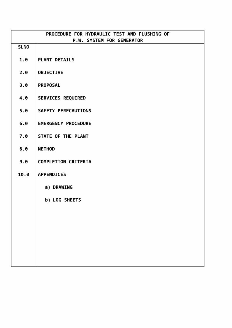
PLANT DETAILS:
The Primary Water System (Stator water System) consists of the following
2 Nos of Primary water pumps
2 Nos of filters.
P.W. cooler unit consisting of 3 Nos of coolers.
Measuring instrument rack.
Polishing Unit
Inter connecting pipe lines, including DM make up line and ACW lines.
Primary water tank with level Indicator and Nitrogen pressurized connecting lines.
Plant Item completion list for Mechanical, Electrical and C & I are to be prepared at site.
The schematic of Primary Water system is enclosed in Section 10.0(Drg.No. 4:PS:TSX:0065:00)
Note: While flushing & HT, original drawing (No:0-153-00-01048, 0-149-00-01131) may be referred.
STATUS
Signatures
NTPC BHEL

Station: NTPC- RAMAGUNDAM
BHEL Ref No.PS-DC-202-500-0019NTPC Ref no OS-COMM-RGM-Commg-PRO-018 Sheet 3 of 14
Plant area: TURBINEPROCEDURE FOR HYDRAULIC TEST AND FLUSHING OF
P.W. SYSTEM FOR GENERATORSLNO
2.0
2.1
3.0
3.1
4.0
4.1
4.2
4.3
4.4
4.5
4.6
OBJECTIVES:
The flushing of PW system is to remove any dust, dirt or foreign particles from the pipings erected at site and to ensure the cleanliness of the complete system before admitting the water into generator stator winding.
PROPOSAL:
The cleaning of PW system in carried out in two stages.
a. Rinsing of the pipe lines and tank.
b. Flushing of the system with the primary water pumps.
In both the above, Stator winding and Generator bushing are isolated.
SERVICES REQUIRED:
Availability of Manpower with required tools for attending any leak & cleaning of filters.
Availability of Operating personnel to co-ordinate the activities.
Availability of Lighting arrangements in the operating floors.
Availability of Portable fire fighting equipments in all the floors.
Availability of sufficient quantity of DM Water.
Availability of L.T Power Supply
STATUS
Signatures
NTPC BHEL
Station: NTPC- RAMAGUNDAM
BHEL Ref No.PS-DC-202-500-0019NTPC Ref no OS-COMM-RGM-Commg-PRO-018 Sheet 4 of 14
Plant area: TURBINEPROCEDURE FOR HYDRAULIC TEST AND FLUSHING OF
P.W. SYSTEM FOR GENERATORSLNO
4.7
4.8
5.0
5.1
5.2
5.3
6.0
6.1
6.2
6.3
Availability of Nitrogen for the activity
Availability of Cooling Water.
SAFETY PRECAUTIONS:
Display of Board “No cutting / welding” at all floors.
Debris in all floors shall be removed.
Approach / Stair case / platform where ever required are made available.
EMERGENCY PROCEDURE:
First Aid kit shall be made available.
The test team should know well about the procedure to be adopted in case of damage to machinery or injury to any personnel connected to the activity.
The test team should be well aware of procedures to be adopted in case of any abnormality in the activity.
STATUS
Signatures
NTPC BHEL
Station: NTPC- RAMAGUNDAM
BHEL Ref No.PS-DC-202-500-0019NTPC Ref no OS-COMM-RGM-Commg-PRO-018 Sheet 5 of 14
Plant area: TURBINEPROCEDURE FOR HYDRAULIC TEST AND FLUSHING OF
P.W. SYSTEM FOR GENERATORSLNO
7.0
7.1
7.2
7.3
7.4
7.5
7.6
7.7
7.8
7.9
7.10
7.11
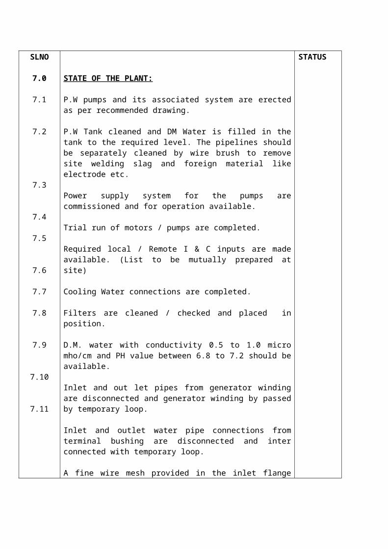
STATE OF THE PLANT:
P.W pumps and its associated system are erected as per recommended drawing.
P.W Tank cleaned and DM Water is filled in the tank to the required level. The pipelines should be separately cleaned by wire brush to remove site welding slag and foreign material like electrode etc.
Power supply system for the pumps are commissioned and for operation available.
Trial run of motors / pumps are completed.
Required local / Remote I & C inputs are made available. (List to be mutually prepared at site)
Cooling Water connections are completed.
Filters are cleaned / checked and placed in position.
D.M. water with conductivity 0.5 to 1.0 micro mho/cm and PH value between 6.8 to 7.2 should be available.
Inlet and out let pipes from generator winding are disconnected and generator winding by passed by temporary loop.
Inlet and outlet water pipe connections from terminal bushing are disconnected and inter connected with temporary loop.
A fine wire mesh provided in the inlet flange joint of P.W. Tank.
STATUS
Signatures
NTPC BHEL
Station: NTPC- RAMAGUNDAM
BHEL Ref No.PS-DC-202-500-0019NTPC Ref no OS-COMM-RGM-Commg-PRO-018 Sheet 6 of 14
Plant area: TURBINEPROCEDURE FOR HYDRAULIC TEST AND FLUSHING OF
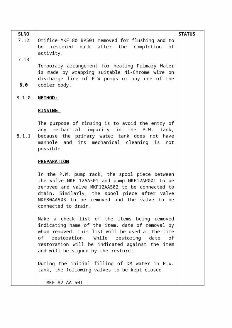
P.W. SYSTEM FOR GENERATORSLNO7.12
7.13
8.0
8.1.0
8.1.1
Orifice MKF 80 BP501 removed for flushing and to be restored back after the completion of activity.
Temporary arrangement for heating Primary Water is made by wrapping suitable Ni-Chrome wire on discharge line of P.W pumps or any one of the cooler body.
METHOD:
RINSING
The purpose of rinsing is to avoid the entry of any mechanical impurity in the P.W. tank, because the primary water tank does not have manhole and its mechanical cleaning is not possible.
PREPARATION
In the P.W. pump rack, the spool piece between the valve MKF 12AA501 and pump MKF12AP001 to be removed and valve MKF12AA502 to be connected to drain. Similarly, the spool piece after valve MKF80AA503 to be removed and the valve to be connected to drain.
Make a check list of the items being removed indicating name of the item, date of removal by whom removed. This list will be used at the time of restoration. While restoring date of restoration will be indicated against the item and will be signed by the restorer.
During the initial filling of DM water in P.W. tank, the following valves to be kept closed.
MKF 82 AA 501 MKF 80 AA 503 MKF 12 AA 501 MKF 22 AA 501 MKF 83 AA 502 MKF 83 AA 501 MKF 80 AA 504
STATUS
Signatures
NTPC BHEL
Station: NTPC- RAMAGUNDAM
BHEL Ref No.PS-DC-202-500-0019NTPC Ref no OS-COMM-RGM-Commg-PRO-018 Sheet 7 of 14
Plant area: TURBINEPROCEDURE FOR HYDRAULIC TEST AND FLUSHING OF
P.W. SYSTEM FOR GENERATORSLNO
8.1.2
8.1.3
8.1.4
8.1.5
PROCESS
The rinsing is carried out in the following steps:
STEP – I
After filling the tank, the valve MKF 12 AA 501 should be opened and water is drained for the cleaning of the pump suction pipe from the P.W. tank. This is repeated 2-3 times and then valve MKF12AA501 should be closed.
STEP – II
After filling the tank, the valve MKF83AA502, MKF83AA501, MKF80AA504, MKF80AA503 should be opened so that the recirculation line as well as the bushing supply lines are cleaned. This step should be repeated 2-3 times and then the valves MKF83AA502, MKF83AA501, MKF80AA504, MKF80AA503 should be closed.
STEP – III
For cleaning the P.W. supply to generator P.W. inlet header, a temporary connection is to be made between the P.W. supply line and the P.W tank (ref. Fig.1). The P.W. tank is filled with D.M. water and the valves MKF82AA501 and MKF80AA503 should be opened for the cleaning of P.W. supply line. This step is repeated 2-3 times and the valves MKF82AA501 and MKF80AA503 should be closed.
STATUS
Signatures
NTPC BHEL
Station: NTPC- RAMAGUNDAM
BHEL Ref No.PS-DC-202-500-0019NTPC Ref no OS-COMM-RGM-Commg-PRO-018 Sheet 8 of 14
Plant area: TURBINEPROCEDURE FOR HYDRAULIC TEST AND FLUSHING OF
P.W. SYSTEM FOR GENERATORSLNO
8.2.0
8.2.1
8.2.2
8.2.3
8.2.4
FLUSHING OF THE P.W.SYSTEM
PREPARATION
After the rinsing is over, the spool pieces after the valves MKF12AA501 and MKF80 AA503 which were removed for rinsing should be connected as per the schematic drawing.
PROCESS:
The process is carried out in the following stages.
STAGE – I (Flushing of Generator Inlet Header)
The connection as per above sketch should be completed. The primary water should be filled with the DM water keeping the valvesMKF12AA501,MKF22AA501,MKF80AA503&MKF82AA501 open and the system should be checked for leakage, if any. The vent valves should be operated to vent the system. In the first step, the flushing of the P.W. line for the generator inlet header is to be carried out. After filling the system, run either of primary water pumps MKF12AP001 or MKF11AP001 for flushing keeping valves MKF80AA504 & MKF83AA501 closed. While the water is in circulation, heat the DM water up to 750 C with the heating arrangement provided and initially throughout the flushing. The filter should be changed over for few times after every 3-4 hours and standby filters should be taken into service.
STATUS
Signatures
NTPC BHEL
Station: NTPC- RAMAGUNDAM
BHEL Ref No.PS-DC-202-500-0019NTPC Ref no OS-COMM-RGM-Commg-PRO-018 Sheet 9 of 14
Plant area: TURBINEPROCEDURE FOR HYDRAULIC TEST AND FLUSHING OF
P.W. SYSTEM FOR GENERATORSLNO
8.2.5
8.2.6
8.2.7
8.2.8
8.2.9
8.2.10
The fine wire mesh provided in the inlet line of P.W. tank at flange joints is to be removed after 4 hours of pump running.
When the filter elements are observed clean after keeping in operation for 8 hours, the other cooler should be taken into service one by one and the cooler already in service should be isolated.
The flushing should be declared completed when the filter remains in clean condition after 8 hours of operation. The system should be drained completely.
STAGE – II (Flushing of Generator Bushing PW lines)
The P.W. system should be normalized as per the original scheme while retaining temporary looping for the inlet and outlet of bushing P.W. connection. After filling the system, either of the pumps should be run, keeping the valve MKF82AA501 closed. The flushing should be completed as per the criteria described in 8.10.4.
STAGE – III
During this stage, all impulse lines for instruments and P.W. tank are flushed.
Flushing of impulse lines
Open the root valve provided in impulse line one by one and flush the D.M. water to atmosphere till clear water flows out. During this step, fresh D.M. water make up valve MKF60AA520 may be operated to maintain water level in P.W. tank.
STATUS
Signatures
NTPC BHEL

Station: NTPC- RAMAGUNDAM
BHEL Ref No.PS-DC-202-500-0019NTPC Ref no OS-COMM-RGM-Commg-PRO-018 Sheet 10 of 14
Plant area: TURBINEPROCEDURE FOR HYDRAULIC TEST AND FLUSHING OF
P.W. SYSTEM FOR GENERATORSLNO
8.2.11
8.3.0
8.3.1
Flushing of P.W. tank / Waste gas line
To flush the tank, stop P.W. pumps and close valve MKF91AA502 provided in Nitrogen feed line to P.W. tank. Open valve no. MKF91AA513 and MKF91AA505 and close valve No. MKF91AA506 Provided in waste gas line. Open DM water filling line inlet valve No.MKF60AA520 and increase the water level in P.W. tank. DM water will flow to atmosphere through waste gas line after P.W tank is filled. Continue flushing of P.W. tank till clean water comes out from the waste gas line. Close the filling line valve no. MKF60AA520.
Pressure Test of Primary Water System
Pressure test of P.W system is performed to check the tightness of all components joints in the system including the stator winding. This test is done after the charging of stator winding and terminal bushing with primary water. This test is to be carried out before boxing up generator casing. This test is carried out in two stages:
Stage 1 :
For external pipe connections.
Stage 2 :
For primary water tank with expansion joints Teflon hoses and winding including terminal bushings.
STATUS
Signatures
NTPC BHEL
Station: NTPC- RAMAGUNDAM
BHEL Ref No.PS-DC-202-500-0019NTPC Ref no OS-COMM-RGM-Commg-PRO-018 Sheet 11 of 14
Plant area: TURBINEPROCEDURE FOR HYDRAULIC TEST AND FLUSHING OF
P.W. SYSTEM FOR GENERATORSLNO
8.3.2
8.3.3
Pre-requisite
Before performing the pressure test of primary water system, the completion of following works should be ensured:
i) That stator winding and terminal bushings have been filled with De- oxygenated primary water of required quality.
ii) N2 gas cylinders are connected at N2 cylinder rack and sufficient numbers of N2 cylinders are available for raising the pressure.
iii) Replace pressure gauge provided in waste gas line MKF91 CP 501 with the range of 0-6 Kg/cm2 and least count of 0.01 kg/cm2 .
iv) Close valve MKG91 AA 506 in waste gas line.
v) Ensure PW tank is filled with DM water up to ¾ of level gauge glass.
Pressure Test of External Piping & System Components
The following system components and pipings are pressure tested at 10 Kg/cm2 for 30 Hrs.
i) Pipe from pump discharge to P.W cooler unit.
ii) P.W collers
iii) Pipe between PW cooler unit and filters.
STATUS
Signatures
NTPC BHEL
Station: NTPC- RAMAGUNDAM
BHEL Ref No.PS-DC-202-500-0019NTPC Ref no OS-COMM-RGM-Commg-PRO-018 Sheet 12 of 14
Plant area: TURBINEPROCEDURE FOR HYDRAULIC TEST AND FLUSHING OF
P.W. SYSTEM FOR GENERATORSLNO
8.3.4
iv) Filters.
v) Water Inlet Pipe upto isolating valves MKF82 AA 501 and MKF83 AA 501.
Pressurisation of the system is done by running one of PW pumps as follows:
- Close valves MKF82 AA 501, MKF83 AA 501, MKF80 AA 504 and MKF60 AA 502.
- Start PW pump MKF22 AP 001 and raise discharge Pr. Up to normal operating pressure of the pump in Pr. Gauge MKF22 CP 501 by slowly opening pump discharge valve. Now raise the pressure further to 10 kg/cm2 by external pressurizing pump / hand pump.
- Check for any visible leakage.
After test is completed, system should be normalized.
Pressure Test of Stator Winding
The primary water tank is pressurized to 6 bar with the help of N2 gas for checking the tightness of PW system. The same is carried out as following.
i) Stop P.W. Pumps
ii) Open Valve MKG31 AA 502, MKG31 AA 503, MKG35 AA 501 and MKF91 AA 502 in N2 gas feed line to P.W. tank.
STATUS
Signatures
NTPC BHEL
Station: NTPC- RAMAGUNDAM
BHEL Ref No.PS-DC-202-500-0019NTPC Ref no OS-COMM-RGM-Commg-PRO-018 Sheet 13 of 14
Plant area: TURBINEPROCEDURE FOR HYDRAULIC TEST AND FLUSHING OF
P.W. SYSTEM FOR GENERATORSLNO
8.3.5
iii) Adjust N2 gas Pr. Regulator NKG31 AA 001 to 6 Kg/cm2.
iv) Open the N2 gas cylinder regulating valve and fill N2 gas in primary water tank. Observe the pressure in PW tank by pressure gauge provided in water gas line.
v) Stop filling N2 gas as soon as 6 Kg.cm2 N2 Pr. is achieved in P.W tank and close valve MKG31 AA 502.
vi) Check for visual inspection for any water leakage / seepage from the various joints of primary water system and stator winding portion. The test should be performed for 48 Hrs. to check pressure drop of system.
Normalisation of System
On completion of pressure test the system is normalized as follows:
i) Open valve MKG91 AA 506 to release the N2 gas PW tank and maintain pressure about 0.2 Kg/cm2 in PW tank with the help of pressure relief valve MKF91 AA 003.
ii) Replace Pr. gauge provided at MKF91 CP 501 with the required pressure range.
iii) Put back the Orifice MKF 80 BP501
iv) The generator casing man holes covers can be closed for air tightness of generator casing.
v) Remove temporary heating arrangement.
vi) Clean both the filters and re-assemble.
STATUS
Signatures
NTPC BHEL
Station: NTPC- RAMAGUNDAM
BHEL Ref No.PS-DC-202-500-0019NTPC Ref no OS-COMM-RGM-Commg-PRO-018 Sheet 14 of 14
Plant area: TURBINEPROCEDURE FOR HYDRAULIC TEST AND FLUSHING OF
P.W. SYSTEM FOR GENERATORSLNO
9.0
vii) Mount all the instrument provided in the system after its proper calibration.
viii) Remove temporary by-pass line provided in inlet / outlet water header of generator winding terminal bushing and connect the header to respective flange connection.
ix) Start P.W. Pump for circulation of primary water.
COMPLETION CRITERIA:
Flushing of P.W. system for Generator declared completed when the filter remains in clean condition after 8 hours of operation.
Half hourly P.W. outlet sample conductivity is almost steady for at least three consecutive readings.
STATUS
Signatures
NTPC BHEL
LOG SHEET
P.W PUMP NO. 1 / 2
Sl.No Date/Time Pump Dis.Pr.Oil temperature
Thermal Shock RemarksBef.
CoolerAfter
Cooler
Signatures
NTPC BHEL

PROCEDURE FOR HYDRAULIC TEST AND FLUSHING OF P.W. SYSTEM FOR GENERATOR

SCHEME FOR STATOR WATER FLUSHING (P.W)
DRG.NO.4:PS:TSX:0152:00Drawn Checked Apprd DateKJ MKS KB 08.09.03
PROJECT M/S RAMAGUNDAM 500 MW
PROCEDURE HYDRAULIC TEST AND OIL FLUSHING OF PW SYSTEM
PURPOSE OF DOCUMET FOR EXECUTION / INFORMATION
DOCUMENT PS:TSX:181:00:03
Copy No:
Issued to :
00 KJ MKS KB 08.09.2003
Rev.No. Prepared by Reviewed by Approved by Date
BHARAT HEAVY ELECTRICALS LIMITEDPSSR/TECHNICAL SERVICES
474, Anna Salai, Nandanam,Chennai – 600 035.