Embed Size (px)
Citation preview

Pumping Apparatus Driver/Operator — Lesson 9
Pumping Apparatus Driver/Operator Handbook, 2nd Edition
Chapter 9 — Fireground Hydraulic Calculations
Pumping Apparatus Driver/Operator
9–2
Learning Objectives
1.List methods for determining pressure loss and required pump discharge pressure on the fireground.
2.Select facts about flowmeters.
3.Answer questions about flowmeter applications.
4.Analyze waterflow problems.(Continued)

Pumping Apparatus Driver/Operator
9–3
Learning Objectives
5.Select facts about hydraulic calculators.
6.Answer questions about pump charts.
7.Interpret a pump chart.
8.Create a pump chart.
(Continued)

Pumping Apparatus Driver/Operator
9–4
Learning Objectives
9.Select facts about the hand method.
10. Use the hand method to calculate total pressure loss.
11. State the equations for determining friction loss using the Condensed “Q” formula.
12. Use the Condensed “Q” formula to calculate total pressure loss.
(Continued)

Pumping Apparatus Driver/Operator
9–5
Learning Objectives
13. Select facts about the GPM flowing method.
14. Use the GPM flowing method to calculate total pressure loss.

Pumping Apparatus Driver/Operator
9–6
Methods for Determining Pressure Loss and Required Pump Discharge Pressure
• Flowmeters
• Hydraulic calculators
• Pump charts
• Hand method
• Condensed “Q” formula
• GPM flowing method

Pumping Apparatus Driver/Operator
9–7
Flowmeters
• Provide water flow in gpm (L/min); displayed number requires no further calculation
• Are particularly advantageous when supplying hoselines or master stream devices equipped with automatic nozzles
(Continued)

Pumping Apparatus Driver/Operator
9–8
Flowmeters
• Can make it possible for driver/operators to pump the correct volume of water to nozzles without knowing the length of hoseline, the amount of friction loss, or whether the nozzles are above or below the pump
• Are allowed to be used instead of pressure gauges on all discharges 1½ to 3 inches (38 mm to 77 mm) in diameter
(Continued)

Pumping Apparatus Driver/Operator
9–9
Flowmeters
• Can be used on discharges that are 3½ inches or larger, but must also have an accompanying pressure gauge
• Must provide a readout in increments no larger than 10 gpm (38 L/min)
(Continued)

Pumping Apparatus Driver/Operator
9–10
Flowmeters
• Paddlewheel– Was the first type of flowmeter used on
apparatus– Is mounted in the top of a straight section of
pipe so that little of the device extends into the waterway
– Decreases sediment deposit – Measures the speed at which the paddlewheel
is spinning and translates that information into a flow measurement
(Continued)

Pumping Apparatus Driver/Operator
9–11
Flowmeters
Courtesy Fire Research Corporation (Continued)

Pumping Apparatus Driver/Operator
9–12
Flowmeters
• Spring probe– Is gaining increasing use in the fire service
– Uses a stainless steel spring probe to sense water movement in the discharge piping; the greater the flow of water through the piping, the more the spring probe is forced to bend
– Has only one moving part, so relatively maintenance free
(Continued)

Pumping Apparatus Driver/Operator
9–13
Flowmeters
• Spring probe flowmeter
(Continued)

Pumping Apparatus Driver/Operator
9–14
Flowmeters
• Should be accurate to a tolerance of +/- 3 percent, when properly calibrated and in good working condition
• Have a discharge readout display mounted within 6 inches (150 mm) of the valve control for each discharge equipped
Pumping Apparatus Driver/Operator
9–15
Central Flowmeter Device
• Provides– Flow through any particular discharge at that
time
– Total amount of water being flowed through the pump at that time
– Total amount of water that has been flowed through the pump for the duration of that incident
– Amount of foam being flowed

Pumping Apparatus Driver/Operator
9–16
Flowmeter Applications
• Diagnosing waterflow problems
• Relay pumping
• Standpipe operations

Pumping Apparatus Driver/Operator
9–17
Diagnosing Waterflow Problems
• If the flow does not increase when the driver/operator increases pressure, several problems are likely – kinks, a closed valve, etc.
• If water volume at the nozzle has suddenly diminished but there is no reduction in the flowmeter reading, it can be assumed that a hose has burst.

Pumping Apparatus Driver/Operator
9–18
Relay Pumping
• Use of a flowmeter during relay pumping makes it possible to feed a supply line without having to know the number of gallons (liters) flowing from the pumper receiving the water.
(Continued)

Pumping Apparatus Driver/Operator
9–19
Relay Pumping
1.Monitor the master discharge gauge and the flowmeter as the throttle is increased during the setup stage of the operation; as engine speed increases, so does the discharge and the gpm (L/min) reading from the flowmeter.
(Continued)

Pumping Apparatus Driver/Operator
9–20
Relay Pumping
2.Increase engine speed until flowmeter reading no longer increases, setting the pump at the correct discharge pressure to supply an adequate flow to the receiving pumper.
(Continued)

Pumping Apparatus Driver/Operator
9–21
Relay Pumping
3.Watch the flowmeter to monitor the water volume being used by the receiving pumper.
4.Watch the master intake pressure gauge. Do not allow the incoming pressure to drop too much below 20 psi (140 kPa).

Pumping Apparatus Driver/Operator
9–22
Standpipe Operations
• When pumping to standpipes, it is difficult to determine where hoselines and nozzles are being placed in a multistory building.
• Using a flowmeter can determine the number and type of nozzles connected to the standpipe, add the maximum rated flow for each nozzle flowing, and then pump the volume of water that matches this figure.
(Continued)

Pumping Apparatus Driver/Operator
9–23
Standpipe Operations
• It is important that the driver/operator be in communication with the firefighters on the nozzles to ensure that nozzle pressures and reactions are correct.
• Once a hoseline is charged, there is no flow through the system until a nozzle is opened.
(Continued)

Pumping Apparatus Driver/Operator
9–24
Standpipe Operations
• Set the pump for a pressure that is close to what is required when the nozzle is flowing.
• Once the nozzle is fully opened and flowing, adjust the pressure until the appropriate amount of water is flowing.

Pumping Apparatus Driver/Operator
9–25
Hydraulic Calculators
• Enable the driver/operator to determine the pump discharge pressure required to supply a hose layout without having to perform tedious mental hydraulic calculations
(Continued)

Pumping Apparatus Driver/Operator
9–26
Hydraulic Calculators
• Manual or mechanical — Operate by moving a slide or dial in which the water flow, size of hose, and length of the hose lay are indicated
(Continued)

Pumping Apparatus Driver/Operator
9–27
Hydraulic Calculators
• Electronic– Allow the driver/operator to input the known
information: water flow, size of hose, length of hose lay, elevation changes
– Computes required pump discharge pressure using preprogrammed formulas
– Portable or mounted near the pump panel
– Inexpensive programmable calculators can be preprogrammed and carried on apparatus.

Pumping Apparatus Driver/Operator
9–28
Pump Charts
• Are used by some fire departments to reduce the need for calculations on the emergency scene
• Contain the required pump discharge pressures for various hose lays and assemblies used within that jurisdiction
(Continued)

Pumping Apparatus Driver/Operator
9–29
Pump Charts
• May be placed on laminated sheets carried on the apparatus or on plates that are affixed to the pump panel
• May be developed by fire departments or supplied by fire hose or nozzle manufacturers

Pumping Apparatus Driver/Operator
9–30
Pump Chart Columns
• Nozzle column — Includes nozzles and devices used by the department developing the chart; includes applications such as sprinkler system support or relay pumping operations
• GPM (L/min) column — Indicates the flow being provided to that nozzle or layout
(Continued)

Pumping Apparatus Driver/Operator
9–31
Pump Chart Columns
• NP column — Indicates the nozzle pressure being produced
• 100, 200, etc. (30, 60, etc.) columns — Indicate the number of feet (meters) of hose being used to supply a given nozzle or layout

Pumping Apparatus Driver/Operator
9–32
How to Use Pump Charts
1.Locate a nozzle column and the nozzle or layout being used.
2.Follow that line across to the vertical column headed by the number of feet (meters) of hose in that layout.
3.The figure in the block where the two columns intersect is the required pump discharge pressure.

Pumping Apparatus Driver/Operator
9–33
Developing a Pump Chart
• Identify all nozzles, devices, and layouts used by the department and enter them in the nozzle column.
• Enter gpm (L/min) flowing and the nozzle pressure desired for each item in the appropriate columns.
• Calculate the required pump discharge pressures for each of the listed layouts.

Pumping Apparatus Driver/Operator
9–34
Calculating Pressures for Pump Charts
• Be certain to include friction loss in master stream appliances flowing in excess of 350 gpm (1 400 L/min).
• For wyed hoselines, the length of layout numbers indicate the number of feet (meters) of hose between the pumper and the wye.
(Continued)

Pumping Apparatus Driver/Operator
9–35
Calculating Pressures for Pump Charts
• When a master stream nozzle may be supplied by a different number or size of hoselines, indicate these on the chart.
• Round pump discharge pressure to the nearest 5 psi (35 kPa).
• Do not list pump discharge pressures that exceed the test pressure used for the size of hose concerned or the pump test pressure.
(Continued)

Pumping Apparatus Driver/Operator
9–36
Calculating Pressures for Pump Charts
• When calculating pump discharge pressures for relay operations, provide established departmental residual pressures at the intake of the pumper being supplied. This residual pressure may be indicated on the chart as a nozzle pressure.

Pumping Apparatus Driver/Operator
9–37
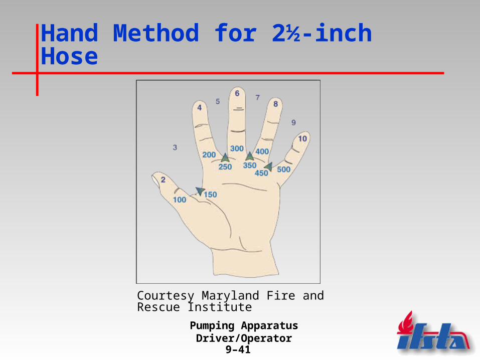
Hand Method for 2½-inch Hose
1.Starting with the thumb of the left hand, each finger is numbered at the base in terms of hundreds of gpm.
2.Returning to the thumb, and again moving from left to right, the tip of each finger is given a successive even number, beginning with two.
(Continued)

Pumping Apparatus Driver/Operator
9–38
Hand Method for 2½-inch Hose
3.Because nozzle capacities vary in gpm, the nearest half-hundred can be used with slight variations. The numbers 3, 5, 7, and 9 can be used for flows of 150, 250, 350, and 450 gpm, respectively. These half-hundred figures can be assigned to the spaces between the fingers.
(Continued)

Pumping Apparatus Driver/Operator
9–39
Hand Method for 2½-inch Hose
4.The friction loss for 100 feet of 2½-inch hose at a desired flow is determined by selecting the finger to which the desired flow has been assigned, and multiplying the number at the tip of the finger by the first digit at the base of the finger.
(Continued)

Pumping Apparatus Driver/Operator
9–40
Hand Method for 2½-inch Hose
5.The answers provided by this method give a reasonable estimate of the friction loss that can be expected in that hoseline. If more accurate figures are required, one of the other methods previously discussed in this curriculum needs to be employed.
(Continued)
Pumping Apparatus Driver/Operator
9–41
Hand Method for 2½-inch Hose
Courtesy Maryland Fire and Rescue Institute

Pumping Apparatus Driver/Operator
9–42
Hand Method for 1¾-inch Hose
• Calculate the friction loss in 100 feet of 1¾-inch hose by going to the finger that corresponds to the flow you are using and multiplying the number at the tip of the finger by the number at the base of the same finger.

Pumping Apparatus Driver/Operator
9–43
Determining Friction Loss Using the Condensed “Q” Formula
• 3-inch hose (with 2½- or 3-inch couplings)
FL per 100 feet = Q2
FL = Friction loss in 100 feet of 3-inch hose
Q = Number of hundreds of gpm
Note: The amount of friction loss calculated using this formula will be 20% greater than if the same situation is calculated using FL = CQ2L.
(Continued)

Pumping Apparatus Driver/Operator
9–44
Determining Friction Loss Using the Condensed “Q” Formula
• 4-inch hose
FL per 100 feet = Q2
5
FL = Friction loss in 100 feet of 4-inch hose
Q = Number of hundreds of gpm
(Continued)
Pumping Apparatus Driver/Operator
9–45
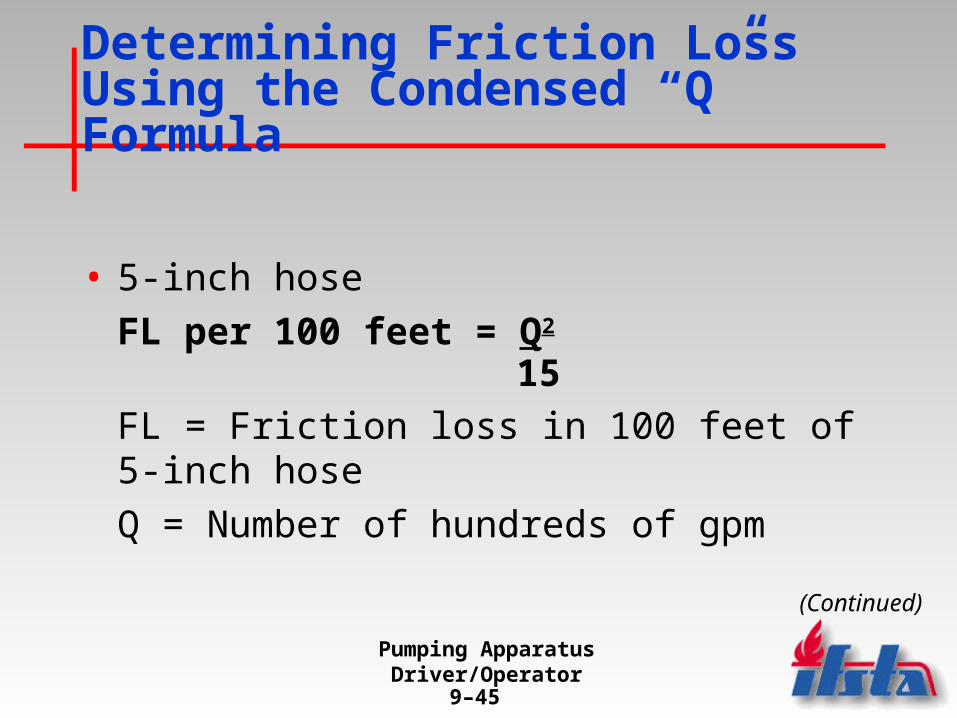
Determining Friction Loss Using the Condensed “Q” Formula
• 5-inch hose
FL per 100 feet = Q2
15
FL = Friction loss in 100 feet of 5-inch hose
Q = Number of hundreds of gpm
(Continued)

Pumping Apparatus Driver/Operator
9–46
GPM Flowing Method
• Permits friction loss to be calculated from the gpm flow
• Is applicable to both solid and fog streams
• Can be used for hose sizes other than 2½-inch

Pumping Apparatus Driver/Operator
9–47
GPM Flowing Methodfor 2½-inch Hose
1.Find the flow in gpm from a nozzle at a specified pressure.
2.Subtract 10 from the first two numbers of the gpm flow in order to derive a sufficiently accurate friction loss figure per 100 feet of 2½-inch hose.

Pumping Apparatus Driver/Operator
9–48
GPM Flowing Methodfor 1½-inch Hose
1.Find the flow in gpm from a nozzle at a specified pressure.
2.Multiply the flow times four.
3.Subtract 10 from the first two numbers of the gpm flow in order to derive a sufficiently accurate friction loss figure per 100 feet of 1½-inch hose.
Pumping Apparatus Driver/Operator
9–49
Summary
• Fireground situations are often loud and chaotic scenes that make performing complex mental calculations difficult for driver/operators.
• Many departments train driver/operators to use flowmeters, hydraulic calculators, pump charts, and simplified methods of determining pressure loss and required pump discharge pressure during fire incidents.

Pumping Apparatus Driver/Operator
9–50
Discussion Questions
1.What are the two types of flowmeters?
2.What are the two types of hydraulic calculators?
3.How many columns are there on a pump chart? Name each column.
(Continued)

Pumping Apparatus Driver/Operator
9–51
Discussion Questions
4.Describe the hand method for determining friction loss.
5.State the equations for determining friction loss using the Condensed “Q” formula.