Embed Size (px)
Citation preview
Pumping Apparatus Driver/ Operator — Lesson 8 Customary
Pumping Apparatus Driver/Operator Handbook, 2nd Edition
Chapter 8 Customary — Theoretical Pressure Calculations

Pumping Apparatus Driver/Operator
8 Customary–2
Learning Objectives
1.Answer questions about friction loss, elevation pressure, and total pressure loss (TPL).
2.State the equation for determining friction loss.
3.Calculate friction loss.
4.Select facts about determining your own friction loss coefficients.
(Continued)
Pumping Apparatus Driver/Operator
8 Customary–3
Learning Objectives
5.Test hose carried on your apparatus to determine friction loss.
6.Answer questions about appliance pressure loss.
7.Select facts about elevation pressure.
8.State the equations for determining elevation pressure. (Continued)

Pumping Apparatus Driver/Operator
8 Customary–4
Learning Objectives
9.Calculate elevation pressure.
10. Answer questions about hose layouts.
11. Calculate total pressure loss in single hoseline layouts.
12. Calculate total pressure loss for wyed hoselines of equal length. (Continued)

Pumping Apparatus Driver/Operator
8 Customary–5
Learning Objectives
13. Calculate total pressure loss for siamesed hoselines of equal length.
14. Calculate total pressure loss for standpipe operations.
15. Calculate total pressure loss for multiple hoselines of unequal length.
(Continued)

Pumping Apparatus Driver/Operator
8 Customary–6
Learning Objectives
16. Calculate total pressure loss for wyed hoselines of unequal length and for manifold hoselines.
17. Calculate total pressure loss for master streams.
18. State the equation for determining pump discharge pressure.
(Continued)

Pumping Apparatus Driver/Operator
8 Customary–7
Learning Objectives
19. Calculate pump discharge pressure.
20. State the equation for determining net pump discharge pressure (NPDP).
21. Calculate net pump discharge pressure.

Pumping Apparatus Driver/Operator
8 Customary–8
Friction Loss andElevation Pressure
• To produce effective fire streams, it is necessary to know the amount of friction loss in the fire hose and any pressure loss or gain due to elevation.
• Causes of friction loss– Hose condition– Coupling condition– Kinks– Volume of water flowing per minute (Continued)

Pumping Apparatus Driver/Operator
8 Customary–9
Friction Loss and Elevation Pressure
• The calculation of friction loss must take into account the length and diameter of the hoseline and any major hose appliances attached to the line. Because the amount of hose used between an engine and the nozzle is not always the same, driver/operators must be capable of determining friction loss in any given length of hose.
(Continued)
Pumping Apparatus Driver/Operator
8 Customary–10
Friction Loss and Elevation Pressure
• Elevation differences, such as hills, gullies, aerial devices, or multistoried buildings, create a pressure loss or gain known as elevation pressure.
• Together, friction loss and elevation pressure loss are referred to as total pressure loss.
Pumping Apparatus Driver/Operator
8 Customary–11
Determining Friction Loss
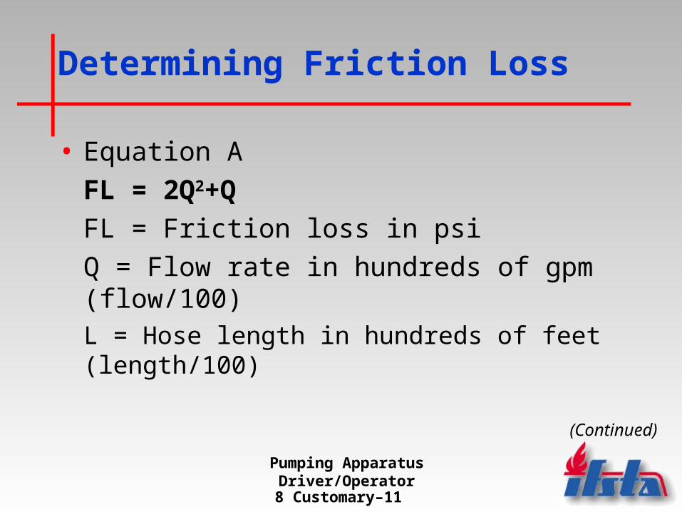
• Equation A
FL = 2Q2+Q
FL = Friction loss in psi
Q = Flow rate in hundreds of gpm (flow/100)L = Hose length in hundreds of feet (length/100)
(Continued)
Pumping Apparatus Driver/Operator
8 Customary–12
Determining Friction Loss
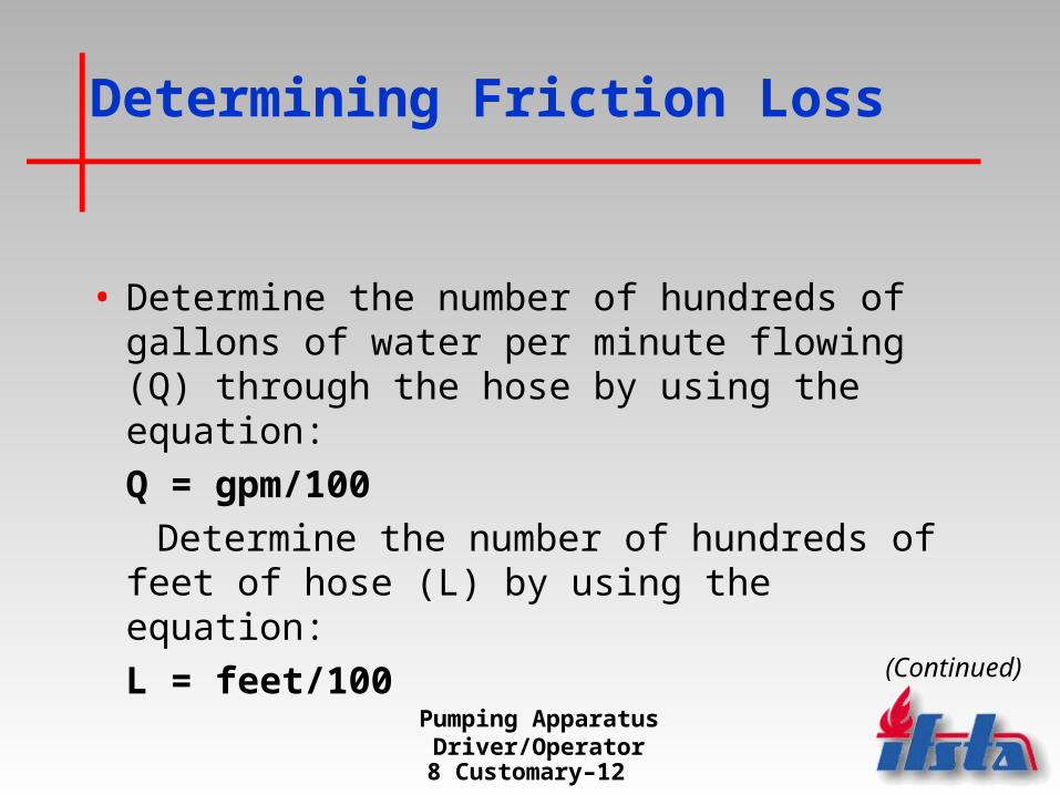
• Determine the number of hundreds of gallons of water per minute flowing (Q) through the hose by using the equation:
Q = gpm/100
Determine the number of hundreds of feet of hose (L) by using the equation:
L = feet/100(Continued)

Pumping Apparatus Driver/Operator
8 Customary–13
Determining Your Own Friction Loss Coefficients
• If you wish to calculate more accurate results for the fire hose that is carried on your apparatus, rather than use the results from the standard friction loss coefficients, it is recommended that you test your hose to determine the actual coefficients.
(Continued)
Pumping Apparatus Driver/Operator
8 Customary–14
Determining Your Own Friction Loss Coefficients
• In order to get results indicative of averages that can be expected on the fireground, it is necessary to use the same hose that would be used on the fireground.
• Conduct tests on hose that is in service, not on hose that has been in storage or hose that has never been put into service (unless new hose is about to be placed into service).
(Continued)

Pumping Apparatus Driver/Operator
8 Customary–15
Determining Your Own Friction Loss Coefficients
• Departments should test only one hose type at a time.
• It is important that all measuring devices are in good condition and properly calibrated.
(Continued)

Pumping Apparatus Driver/Operator
8 Customary–16
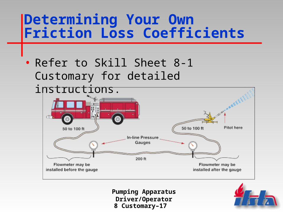
Determining Your Own Friction Loss Coefficients
• Needed equipment– Pitot tube or flowmeter– Two in-line gauges,
calibrated in increments of 5 psi or less
– Hose to be tested– Smoothbore nozzle (if
using pitot tube)– Any type nozzle (if using
flowmeter) (Continued)
Pumping Apparatus Driver/Operator
8 Customary–17
Determining Your Own Friction Loss Coefficients
• Refer to Skill Sheet 8-1 Customary for detailed instructions.

Pumping Apparatus Driver/Operator
8 Customary–18
Appliance Pressure Loss
• Appliances on the fireground include reducers, increasers, gates, wyes, manifolds, aerial apparatus, and standpipe systems.
(Continued)
Pumping Apparatus Driver/Operator
8 Customary–19
Appliance Pressure Loss
• Appliance friction loss is insignificant when the total flow through appliances is less than 350 gpm.
• For this lesson, assume a 0 psi loss for flows less than 350 gpm and a 10 psi loss for each appliance (other than master stream devices) in a hose assembly when flowing 350 gpm or more.
(Continued)

Pumping Apparatus Driver/Operator
8 Customary–20
Appliance Pressure Loss
• Friction loss caused by handline nozzles is not considered in the calculations in this lesson, as it is generally insignificant in the overall pressure in a hose assembly.
• For this lesson, assume a friction loss of 25 psi in all master stream appliances, regardless of the flow.

Pumping Apparatus Driver/Operator
8 Customary–21
Elevation Pressure
• Elevation pressure is created by elevation differences between the nozzle and the pump.
(Continued)

Pumping Apparatus Driver/Operator
8 Customary–22
Elevation Pressure
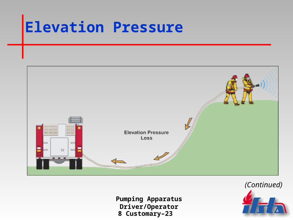
• Water exerts a pressure of 0.434 psi per foot of elevation.
• When a nozzle is operating at an elevation higher than the apparatus, this pressure is exerted back against the pump.
• To compensate for this pressure “loss,” elevation pressure must be added to friction loss to determine total pressure loss.
(Continued)
Pumping Apparatus Driver/Operator
8 Customary–23
Elevation Pressure
(Continued)

Pumping Apparatus Driver/Operator
8 Customary–24
Elevation Pressure
• Operating a nozzle lower than the pump results in pressure pushing against the nozzle.
• This “gain” in pressure is compensated for by subtracting the elevation pressure from the total friction loss.
(Continued)

Pumping Apparatus Driver/Operator
8 Customary–25
Elevation Pressure

Pumping Apparatus Driver/Operator
8 Customary–26
Determining Elevation Pressure
• Equation B
EP = 0.5H
EP = Elevation pressure in psi
0.5 = A constant
H = Height in feet
(Continued)

Pumping Apparatus Driver/Operator
8 Customary–27
Determining Elevation Pressure
• It is generally easier to determine elevation pressure in a multistoried building by another method. By counting the number of stories of elevation, use:
• Equation C
EP = 5 psi x (number of stories)

Pumping Apparatus Driver/Operator
8 Customary–28
Hose Layouts
• The combination of friction loss and elevation pressure is referred to as total pressure loss.
• Pressure changes are possible due to hose friction loss, appliance friction loss (when flows exceed 350 gpm), and any pressure loss or gain due to elevation.
• By adding all the affecting pressure losses, the total pressure loss can be determined for any hose lay.

Pumping Apparatus Driver/Operator
8 Customary–29
Simple Hose Layouts
• Single hoseline
• Multiple hoselines (equal length)
• Wyed hoselines (equal length)
• Siamesed hoselines (equal length)
Pumping Apparatus Driver/Operator
8 Customary–30
Single Hoseline
• Is the most commonly used hose lay
• Presents the simplest friction loss calculations

Pumping Apparatus Driver/Operator
8 Customary–31
Multiple Hoselines (Equal Length)
• When determining the friction loss in equal length multiple lines whose diameters are the same, it is only necessary to perform calculations for one line.
• When the diameters of the hoselines vary, friction loss calculations must be made for each hoseline. The pump discharge pressure is then set for the highest pressure.

Pumping Apparatus Driver/Operator
8 Customary–32
Wyed Hoselines (Equal Length)
• When using a wye, it is important that the attack lines wyed from the supply line are the same length and diameter in order to avoid two different nozzle pressures and an exceptionally difficult friction loss problem.
(Continued)

Pumping Apparatus Driver/Operator
8 Customary–33
Wyed Hoselines (Equal Length)
• When the nozzle pressure, hose length, and diameter are the same on each wyed line, an equal split of the total water flowing occurs at the wye appliance.
• This enables only one of the wyed hoselines to be considered when computing the total pressure lost.
(Continued)

Pumping Apparatus Driver/Operator
8 Customary–34
Wyed Hoselines (Equal Length)
• Step 1 — Compute the number of hundreds of gpm flowing in each wyed hoselines by using the equation:
Q = flow rate (gpm)
100
(Continued)

Pumping Apparatus Driver/Operator
8 Customary–35
Wyed Hoselines (Equal Length)
• Step 2 — Determine the friction loss in one of the wyed attack lines using the equation:
FL = 2Q2+Q
(Continued)
Pumping Apparatus Driver/Operator
8 Customary–36
Wyed Hoselines (Equal Length)
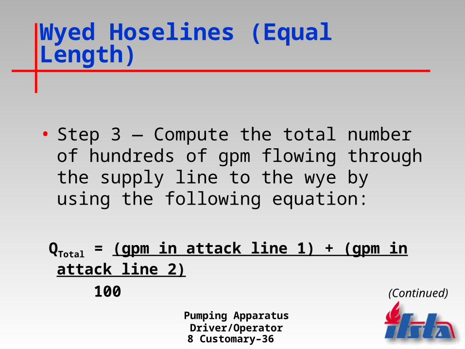
• Step 3 — Compute the total number of hundreds of gpm flowing through the supply line to the wye by using the following equation:
QTotal = (gpm in attack line 1) + (gpm in attack line 2)
100(Continued)

Pumping Apparatus Driver/Operator
8 Customary–37
Wyed Hoselines (Equal Length)
• Step 4 — Determine the friction loss in the supply line using.
(Continued)

Pumping Apparatus Driver/Operator
8 Customary–38
Wyed Hoselines (Equal Length)
• Step 5 — Add the friction loss from the supply line, one of the attack lines, 10 psi for the wye appliance (if the total flow exceeds 350 gpm) and elevation pressure (if applicable) to determine the total pressure loss.

Pumping Apparatus Driver/Operator
8 Customary–39
Siamesed Hoselines (Equal Length)
• When calculating friction loss in siamesed lines, however, it is necessary to use a different set of coefficients than for single hoselines.
(Continued)

Pumping Apparatus Driver/Operator
8 Customary–40
Siamesed Hoselines (Equal Length)
• Step 1 — Compute the total number of hundreds of gpm flowing by using the equation:
Q = gpm flowing
100
(Continued)
Pumping Apparatus Driver/Operator
8 Customary–41
Siamesed Hoselines (Equal Length)
• Step 2 — Determine the friction loss in the attack line
• Step 3 — Determine the amount of friction loss in the siamesed lines
(Continued)
Pumping Apparatus Driver/Operator
8 Customary–42
Siamesed Hoselines (Equal Length)
• Step 4 — Add the friction loss from the siamesed lines, attack line, 10 psi for the siamese appliance (if flow is greater than 350 gpm), and elevation pressure (if applicable) to determine the total pressure loss.

Pumping Apparatus Driver/Operator
8 Customary–43
Complex Hose Layouts
• Standpipe operations
• Multiple hoselines (unequal length)
• Wyed hoselines (unequal length) and manifold hoselines
• Master streams

Pumping Apparatus Driver/Operator
8 Customary–44
Standpipe Operations
• In most cases, fire departments have predetermined pressures that driver/operators are expected to pump into the fire department connection (FDC) of a standpipe system.
(Continued)

Pumping Apparatus Driver/Operator
8 Customary–45
Standpipe Operations
• These pressures are contained in the department’s SOPs, in the pre-incident plan for that particular property, or on a faceplate adjacent to the FDC.
(Continued)
Pumping Apparatus Driver/Operator
8 Customary–46
Standpipe Operations
• In order to be able to determine the required pressure for the standpipe system, it is necessary to determine the total pressure loss.
• Treat the FDC like any other hose appliance.

Pumping Apparatus Driver/Operator
8 Customary–47
Multiple Hoselines (Unequal Length)
• When unequal length hoselines are used, the amount of friction loss varies in each line.
• For this reason, friction loss must be calculated in each hoseline.

Pumping Apparatus Driver/Operator
8 Customary–48
Wyed Hoselines (Unequal Length) and Manifold Hoselines
• Remember that when hose lengths are unequal in length and/or diameter, the total pressure loss in the system is based on the highest pressure loss in any of the lines.
(Continued)
Pumping Apparatus Driver/Operator
8 Customary–49
Wyed Hoselines (Unequal Length) and Manifold Hoselines
• Step 1 — Compute the number of hundreds of gpm flowing in each of the wyed hoselines by using the following equation:
Q = discharge gpm
100
• Step 2 — Determine the friction loss in each of the wyed lines.
(Continued)

Pumping Apparatus Driver/Operator
8 Customary–50
Wyed Hoselines (Unequal Length) and Manifold Hoselines
• Step 3 — Compute the total number of hundreds of gpm flowing in the supply line to the wye or manifold by adding the sum of the flows in the attack lines and dividing by 100.
(Continued)

Pumping Apparatus Driver/Operator
8 Customary–51
Wyed Hoselines (Unequal Length) and Manifold Hoselines
• Step 4 — Determine the friction loss in the supply line
(Continued)
Pumping Apparatus Driver/Operator
8 Customary–52
Wyed Hoselines (Unequal Length) and Manifold Hoselines
• Step 5 — Add the friction loss from the supply line, the wye or manifold appliance (if total flow is greater than 350 gpm), elevation loss, and the wyed line with the greatest amount of friction loss to determine the total pressure loss.

Pumping Apparatus Driver/Operator
8 Customary–53
Master Streams
• Remember to add a 25 psi pressure loss to all calculations involving master stream devices.
(Continued)
Pumping Apparatus Driver/Operator
8 Customary–54
Master Streams
• Determining friction loss for master streams is essentially the same as those used for other fire streams, unless unequal length or diameter hoselines are used to supply a master stream appliance.
• In this situation, use an average of the hose lengths for ease of calculation.
(Continued)
Pumping Apparatus Driver/Operator
8 Customary–55
Master Streams
• Aerial devices with piped waterways are treated in the same manner as master stream appliances: using a friction loss of 25 psi to include the intake, internal piping and nozzle.

Pumping Apparatus Driver/Operator
8 Customary–56
Determining Pump Discharge Pressure
• In order to deliver the necessary water flow to the fire location, the pump discharge pressure at the apparatus must be enough to overcome the sum of all pressure losses.
(Continued)

Pumping Apparatus Driver/Operator
8 Customary–57
Determining Pump Discharge Pressure
• Equation D
PDP = NP + TPL
PDP = Pump discharge pressure in psi
NP = Nozzle pressure in psi
TPL = Total pressure loss in psi (appliance, friction, and elevation losses)
(Continued)

Pumping Apparatus Driver/Operator
8 Customary–58
Determining Pump Discharge Pressure
• It is often important that attack lines be supplied with water at somewhere near the required nozzle pressure until the driver/operator has time to calculate the correct pump discharge pressure.
• It is SOP in many departments to initially charge attack lines with fog nozzles at 100 psi and solid stream nozzles at 50 psi while setting up for the pump operation.
(Continued)

Pumping Apparatus Driver/Operator
8 Customary–59
Determining Pump Discharge Pressure
• Supplying multiple, wyed, or manifold hoselines requires different pump discharge pressures for each attack line.
• Because this is not possible, set the pump discharge pressure for the hoselines with the greatest pressure demand.– Solid stream nozzle (handline) — 50 psi– Solid stream nozzle (master stream) — 80 psi – Standard fog nozzle — 100 psi– Low-pressure fog nozzle — 50 psi or 75 psi

Pumping Apparatus Driver/Operator
8 Customary–60
Determining Net PumpDischarge Pressure
• Centrifugal pumps are able to take advantage of incoming water pressure into the pump.
• Thus, if a pumper is required to discharge 150 psi, and it has an intake pressure of 50 psi coming into the pump, the pump only needs to add 100 psi more to meet the demand. This concept is called net pump discharge pressure (NPDP). (Continued)
Pumping Apparatus Driver/Operator
8 Customary–61
Determining Net PumpDischarge Pressure
• NPDP takes into account all factors that contribute to the amount of work the pump must do to produce a fire stream.
• When a pumper is being supplied by a hydrant or a supply line from another pumper, the NPDP is the difference between the pump discharge pressure and the incoming pressure from the hydrant. (Continued)

Pumping Apparatus Driver/Operator
8 Customary–62
Determining Net PumpDischarge Pressure
• Equation E
NPDPPPS = PDP – Intake reading
NPDPPPS = Net pump discharge pressure from a positive pressure sourcePDP = Pump discharge pressure
Note: This equation does not apply to situations where the pumper is operating at a draft.

Pumping Apparatus Driver/Operator
8 Customary–63
Summary
• To fulfill the primary fireground function of supplying attack crews with an adequate volume of water at pressures that are both safe and effective, driver/operators must be able to make certain hydraulic calculations in the field.
(Continued)

Pumping Apparatus Driver/Operator
8 Customary–64
Summary
• To do this, they must know how to factor in losses in pressure due to friction, as well as pressure losses or gains because of elevation differences.
• In addition, driver/operators must be able to calculate pump pressure required to supply multiple hoselines of varying diameters, lengths, and configurations.
Pumping Apparatus Driver/Operator
8 Customary–65
Discussion Questions
1.What four things can cause friction loss?
2.What is total pressure loss (TPL)?
3.What is the equation for determining friction loss?
(Continued)

Pumping Apparatus Driver/Operator
8 Customary–66
Discussion Questions
4.What are the equations for determining elevation pressure?
5.What are the four types of simple hose layouts?
6.What are the four types of complex hose layouts?
(Continued)

Pumping Apparatus Driver/Operator
8 Customary–67
Discussion Questions
7.What is the equation for determining pump discharge pressure?
8.What is the equation for determining net pump discharge pressure (NPDP)?