Embed Size (px)
Citation preview

Performance of A MIMO-OFDM System to
Different Modulation Schemes in AWGN and
Rayleigh Channels using Simulink
Bakare Rasheed Alade Department of Electrical/Electronics
University of Lagos
Lagos, Nigeria
Abstract— This paper studies and gives emphasis on the
effectiveness of both MIMO (Multiple Input Multiple Output)
and OFDM (Orthogonal Frequency Division Multiplexing) in
communications system. The performance comparison of
various modulation schemes in both OFDM only and MIMO-
OFDM systems in terms of BER (Bit Error Rate) is carried out.
This is done for both AWGN (additive White Gaussian Noise)
channel and Rayleigh Fading channel where channel noise is
considered as the channel condition. The performance analysis
of the entire system is done using designs modelled with
Simulink tool in MATLAB.
Keywords— OFDM; MIMO; Modulation; BER; SNR;
Fading; AWGN;
I. INTRODUCTION
The cellular mobile communications industry has recently
been one of the fastest growing industries of all time, with the
number of users increasing incredibly rapidly [1]. However,
Multipath fading is very much influencing the performance of
wireless communication link [2]. The term fading is applied to
signal loss that changes fairly slowly relative to the signal
bandwidth. This term is usually applied to atmospheric
phenomena, however [3]. The fading may vary with time,
geographical position or radio frequency, and is often
modelled as a random process. Fading may either be due to
multipath propagation and/or Doppler shift from changes in
velocity or the channel, referred to as small scale fading, or
due to shadowing (Large scale fading) from obstacles
affecting [3],[4].
Most communications systems designed aimed at
providing one or combinations of these: bandwidth efficiency,
power efficiency, or cost efficiency. Bandwidth efficiency
describes the ability of a modulation scheme to accommodate
data within a limited bandwidth with low bit-error-rate. Power
efficiency describes the ability of the system to reliably send
information at the lowest practical power level [5].
With the increasing traffic for the wireless communication
the need for the more efficient use of the spectrum available
becomes highly important. Considering a desire for even
higher data rates the long-term 3GPP evolutionary trends
include support towards wider transmission [6].
Obviously as the generation is advancing higher data rates
as well as high spectral efficiency are expected. Of course
achieving these data rates requires careful selection of
multicarrier modulation scheme available. OFDM is one of
the emerging techniques for transmitting at higher data rates
[7]. Orthogonal Frequency Division Multiplexing (OFDM) is
a multi carrier modulation technique that provides high
bandwidth efficiency because the carriers are orthogonal to
each other and multiple carriers share the data among
themselves. The main advantage of this transmission
technique is its robustness to channel fading in wireless
communication environment. OFDM can be seen as either a
modulation technique or a multiplexing technique [8].
Consequently this necessitates the study focusing on the
performance of the MIMO-OFDM system under different
channel conditions in various modulation schemes. The
analysis is done based on simulations using Simulink
simulation tool in MATLAB.
II. OFDM
OFDM is a transmission technique based on the idea of
FDM (Frequency Division Multiplexing). In OFDM, the
transmitter transmits a single data stream over a number of
lower rate orthogonal sub-carriers which made use of the
advanced modulation techniques on each component. This
results in a signal with high resistance to interference. OFDM
can be simply define as a multi-carrier modulation where its
carrier spacing is carefully selected so that each sub-carrier is
orthogonal to the other sub-carrier [9]
A. Functional block of an OFDM System
A simple block diagram of an OFDM System is shown in
fig.1 below.
International Journal of Engineering Research & Technology (IJERT)
IJERT
IJERT
ISSN: 2278-0181
www.ijert.orgIJERTV3IS090430
(This work is licensed under a Creative Commons Attribution 4.0 International License.)
Vol. 3 Issue 9, September- 2014
1512

Fig. 1. Simple block digram of an OFDM system
The functions of the blocks making up the system are
described below.
1) MAPPING of SYMBOLS
Bits are grouped based on the modulation method selected by
the user to form symbols ready for modulation. For
Multicarrier transmission signal bits are sometimes padded
with zeros to make it a multiple of sub- carriers.
2) MODULATION
After mapping is done the symbols are modulated using any
of the different modulation schemes such as M-ary PSK and
M-ary QAM. The major M-ary PSK modulation schemes
include but not limited to BPSK, QPSK and 16PSK. Among
the M-ary QAM are 16QAM, 64QAM and 256QAM.
3) OFDM TRANSMITTER
A serial to parallel conversion on the stream of symbols is
carried out and placing them at the positions of the carriers
along with pilot symbols next to them. An IFFT is then
performed to get the OFDM time signal per block of symbols.
Next is the insertion of guard time (cyclic prefix) to prevent
inter-channel interference.
4) CHANNEL
The channel adds noise to the data output from the OFDM
transmitter.
5) OFDM RECEIVER
The removal of the Guard Band is done. Next is the division
of the time signal into the OFDM blocks. For Each Block FFT
is performed and the symbols of interest is extracted to
exclude the pilot symbols.
6) DEMODULATION
This performs the reverse of modulation process.
7) RECOVERING of SYMBOLS
The bits are recovered from the symbols by unpacking the
symbols.
B. Mathematical Description of an OFDM
Mathematically, the modulated sub-carriers can be represented
as a real part of the complex signal below (1).
Sc t = Ac t ej ωct+∅c t , (1)
Where; ωc is the sub-carrier angular frequency
Ac(t) is the amplitude on the sub-carrier
∅c(t) is the phase modulation on the sub-carrier [9].
Fig. 2. OFDM Sub-channel Spectrum
OFDM consists of many sub-carriers. Therefore, the complex
OFDM signal Ss(t) with N sub-carriers can be written as;
Ss t = 1
NAn An t e
j ωnt+∅n t N-1
n=0 (2)
Note,
ωn = ω0 + n∆ω (3)
Where ∆ω is the sub-carrier spacing in angular frequency.
The amplitude and phase modulation do not change within an
OFDM symbol, hence An t and ∅n t can be rewritten as An
and ∅n [9].
Fig. 3. OFDM System Spectrum
Where; fc is the sub-carrier frequency
Ts is the symbol period.
-6 -4 -2 0 2 4 6-0.4
-0.2
0
0.2
0.4
0.6
0.8
1
1.21/nTs
fc0
fc1
fc2
1/(nTs)
Am
pli
tud
e
International Journal of Engineering Research & Technology (IJERT)
IJERT
IJERT
ISSN: 2278-0181
www.ijert.orgIJERTV3IS090430
(This work is licensed under a Creative Commons Attribution 4.0 International License.)
Vol. 3 Issue 9, September- 2014
1513

III. INTER-SYMBOL INTERFERENCE
In a single carrier system, a single fade or interference can
cause the entire link to fail, but in a multi-carrier system, only
small percentage of the sub-carriers will be affected. The
efficiency of OFDM is brought by the use of parallel data and
OFD with overlapping sub-channels to avoid the use of high
speed equalization and to combat impulsive noise, and multi-
path noise as well as to fully utilize the available bandwidth
[9].
To avoid ISI due to multi-path, successive OFDM symbols are
separated by guard band. This makes the OFDM system
resistant to multi-path effects. OFDM is a widely used
because of its high bandwidth efficiency and robustness
against frequency fading due to multipath propagation [10].
Hence orthogonal frequency division multiplexing (OFDM)
can be used to combat fast fading and frequency-selective
fading. OFDM uses multiple carriers, each operating at a
reduced symbol rate to mitigate the effects of delay spread and
selective fading. The longer symbol times make fast fading
less of an issue, and redundancy over the carrier frequency
reduces the effect of any frequency dropouts [11].
IV. CYCLIC PREFIX AND CYCLIC PREFIX
REMOVAL
Theoretically, the orthogonal of sub-channels in OFDM can
be maintained and individual sub-channels can be completely
separated by the FFT at the receiver. However, these
conditions cannot be obtained in practice due inter-symbol
interference (ISI) and inter-carrier interference (ICI)
introduced by transmission channel distortion.
In order to prevent multi-path components interfering from
one symbol with the next symbol, a cyclically extended guard
interval known as Cyclic Prefix. The cyclic prefix is a replica
of the last samples of the OFDM symbol. This is achieved by
adding partial symbol information of each cycle to the
beginning of the symbol [10], [12]. The ratio of the guard
interval to the useful symbol duration depends on different
systems. Since the insertion of guard interval will reduce data
throughput, Tg is usually less than Ts/4 [10].
The total symbol duration, Td, is given as
Td = Tg + Ts (4)
Where; Tg is the duration of guard interval.
Ts is the duration of useful symbol.
Fig. 4. Cyclic Prefix Insertion illustration
Fig. 5.
V. MULTIPLE ANTENNA
Multiple-antenna systems, called MIMO systems (Multiple
Input Multiple Output). "In" and "out" always refer to the
transmission channel. MI stands for multiple sending
antennas and MO accordingly for multiple receiving antennas
[13].
In essence MIMO is effectively a radio antenna technology as
it uses multiple antennas at the transmitter and receiver to
enable a variety of signal paths to carry the data, choosing
separate paths for each antenna to enable multiple signal
paths to be used [14].
There are also the classic SISO systems (Single In Single
Out) with one sending and one receiving antenna
respectively, as well as combinations such as SIMO and
MISO [13].
MIMO system consists of three components, mainly
transmitter, channel and receiver. Transmitter sends a
multiple data such as X1, X2, X3…….XN from different
transmit antenna and signal is received by each receive
antenna R1, R2, R3……RM simultaneously. The relation
between transmit data and receive data is given by
R1 = H11X1 + H12X2 + ….. H1MXM (5)
R2 = H21X1 + H22X2 + ….. H2MXM (6)
……
RM = HN1X1 + HN2X2 + ….. HNMXM (7)
Where, X = transmitted Signal Vector;
R = Received Signal Vector;
International Journal of Engineering Research & Technology (IJERT)
IJERT
IJERT
ISSN: 2278-0181
www.ijert.orgIJERTV3IS090430
(This work is licensed under a Creative Commons Attribution 4.0 International License.)
Vol. 3 Issue 9, September- 2014
1514
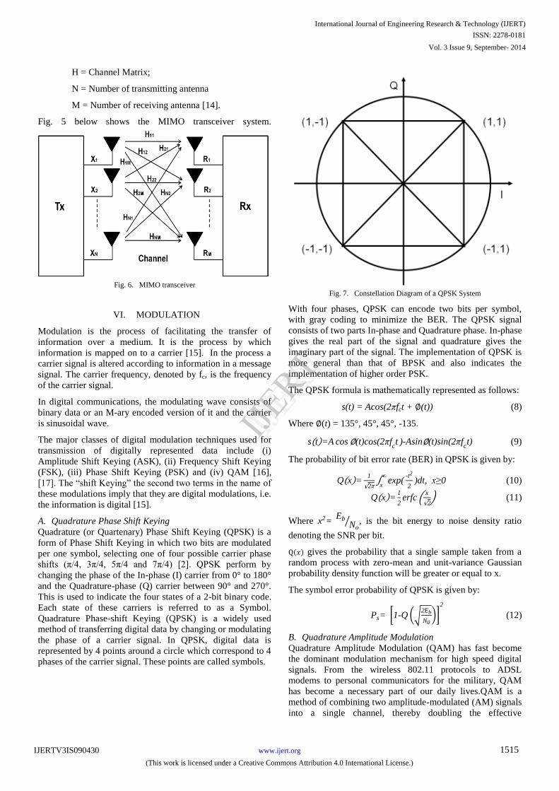
H = Channel Matrix;
N = Number of transmitting antenna
M = Number of receiving antenna [14].
Fig. 5 below shows the MIMO transceiver system.
Fig. 6. MIMO transceiver
VI. MODULATION
Modulation is the process of facilitating the transfer of
information over a medium. It is the process by which
information is mapped on to a carrier [15]. In the process a
carrier signal is altered according to information in a message
signal. The carrier frequency, denoted by fc, is the frequency
of the carrier signal.
In digital communications, the modulating wave consists of
binary data or an M-ary encoded version of it and the carrier
is sinusoidal wave.
The major classes of digital modulation techniques used for
transmission of digitally represented data include (i)
Amplitude Shift Keying (ASK), (ii) Frequency Shift Keying
(FSK), (iii) Phase Shift Keying (PSK) and (iv) QAM [16],
[17]. The “shift Keying” the second two terms in the name of
these modulations imply that they are digital modulations, i.e.
the information is digital [15].
A. Quadrature Phase Shift Keying
Quadrature (or Quartenary) Phase Shift Keying (QPSK) is a
form of Phase Shift Keying in which two bits are modulated
per one symbol, selecting one of four possible carrier phase
shifts (π/4, 3π/4, 5π/4 and 7π/4) [2]. QPSK perform by
changing the phase of the In-phase (I) carrier from 0° to 180°
and the Quadrature-phase (Q) carrier between 90° and 270°.
This is used to indicate the four states of a 2-bit binary code.
Each state of these carriers is referred to as a Symbol.
Quadrature Phase-shift Keying (QPSK) is a widely used
method of transferring digital data by changing or modulating
the phase of a carrier signal. In QPSK, digital data is
represented by 4 points around a circle which correspond to 4
phases of the carrier signal. These points are called symbols.
Fig. 7. Constellation Diagram of a QPSK System
With four phases, QPSK can encode two bits per symbol,
with gray coding to minimize the BER. The QPSK signal
consists of two parts In-phase and Quadrature phase. In-phase
gives the real part of the signal and quadrature gives the
imaginary part of the signal. The implementation of QPSK is
more general than that of BPSK and also indicates the
implementation of higher order PSK.
The QPSK formula is mathematically represented as follows:
s(t) = Acos(2πfct + ∅(t)) (8)
Where ∅(t) = 135°, 45°, 45°, -135.
s t =A cos∅(t)cos(2πfct )-Asin∅(t)sin(2πf
ct) (9)
The probability of bit error rate (BER) in QPSK is given by:
Q x =1
2π exp(
-t2
2
∞
x)dt, x≥0 (10)
Q x =1
2erfc
x
2 (11)
Where x2= Eb
No , is the bit energy to noise density ratio
denoting the SNR per bit.
Q 𝑥 gives the probability that a single sample taken from a
random process with zero-mean and unit-variance Gaussian
probability density function will be greater or equal to x.
The symbol error probability of QPSK is given by:
Ps= 1-Q 2Eb
N0
2
(12)
B. Quadrature Amplitude Modulation
Quadrature Amplitude Modulation (QAM) has fast become
the dominant modulation mechanism for high speed digital
signals. From the wireless 802.11 protocols to ADSL
modems to personal communicators for the military, QAM
has become a necessary part of our daily lives.QAM is a
method of combining two amplitude-modulated (AM) signals
into a single channel, thereby doubling the effective
International Journal of Engineering Research & Technology (IJERT)
IJERT
IJERT
ISSN: 2278-0181
www.ijert.orgIJERTV3IS090430
(This work is licensed under a Creative Commons Attribution 4.0 International License.)
Vol. 3 Issue 9, September- 2014
1515

bandwidth. In a QAM signal, there are two carriers, each
having the same frequency but differing in phase by 90
degrees (one quarter of a cycle, from which the term
quadrature arises). One signal is called the In-phase signal,
and the other is called the Quardrature signal.
Mathematically, one of the signals can be represented by a
sine wave, and the other by a cosine wave. The two
modulated carriers are combined at the source for
transmission. At the destination, the carriers are separated,
the data is extracted from each, and then the data is combined
into the original modulating information. The QAM signal is
mathematically represented as follows:
s t = m1 (t) cos(2πfct )-m2(t)sin(2πf
ct) (13)
Where m1(t) and m2(t) are the two message signals. One of
them is sent in phase i.e. by multiplying it with cos(2πfct) and
the other one is sent in quadrature by multiplying it with
sin(2πfct). Finally, the two signals are added to obtain the
QAM signal. [18]
The symbol error probability of M-ary QAM is given by
Pb≤4erfc 3kEb
(M-1)No
for M =2k (14)
Where k is the number of bits transmitted by each symbol.
VII. NOISE AND INTERFERENCE
In wireless communication, radio propagation refers to the
behaviour of radio waves when they are propagated from
transmitter to receiver [1]. Data are transmitting through the
wireless channel with respective bandwidth to achieve higher
data rate and maintain quality of service. The transmitting
data has to take environmental challenge when it is on air
with against unexpected noise [19]. In the course of
propagation, radio waves are mainly affected by three
different modes of physical phenomena: reflection,
diffraction, and scattering [14].
A. Additive white Gaussian noise
AWGN is often used as a channel model in which the only
impairment to communication is a linear addition of
wideband or white noise with a constant spectral density
(expressed as watts per hertz of bandwidth) and a Gaussian
distribution of amplitude.
The PDF for the AWGN channel is given in (15)
1
σ 2πe
-(x-μ)2
2σ2 (15)
Where µ is the mean and σ is the standard deviation.
The model does not account for fading, frequency selectivity,
interference, nonlinearity or dispersion. However, it produces
simple and tractable mathematical models which are useful
for gaining insight into the underlying behaviour of a system
before these other phenomena are considered.
The AWGN channel is a good model for many satellite and
deep space communication links. It is not a good model for
most terrestrial links because of multipath, terrain blocking,
interference, etc. However, for terrestrial path modeling,
AWGN is commonly used to simulate background noise of
the channel under study, in addition to multipath, terrain
blocking, interference, ground clutter and self interference
that modern radio systems encounter in terrestrial operation
[4].
B. Multipath Fading
A unique characteristic in a wireless channel is a
phenomenon called „fading‟ which is the variation of the
signal amplitude over time and frequency. In contrast with
the additive noise as the most fading common source of
signal degradation, fading is another source of signal
degradation that is non-additive signal disturbance in the
wireless channel. Fading may either be due to multipath
propagation, referred to as multi-path (induced) fading, or to
shadowing from obstacles that affect the propagation of a
radio wave, referred to as shadow fading [17], [20].
Rayleigh and Rician fading channels are useful models of
real-world phenomena in wireless communications. These
phenomena include multipath scattering effects, time
dispersion, and Doppler shifts that arise from relative motion
between the transmitter and receiver.
Some wireless applications, such as standard GSM (Global
System for Mobile Communication) systems, prefer to
specify Doppler shifts in terms of the speed of the mobile. If
the mobile moves at speed v making an angle of θ with the
direction of wave motion, then the Doppler shift is
fd = (vf/c)cos θ (16)
Where; f is the transmission carrier frequency
c is the speed of light.
The Doppler frequency represents the maximum Doppler
shift arising from motion of the mobile.
If the value of θ is zero then maximum Doppler shift results
and from (16),
fd = (vf/c) (17)
Fig. 7 below depicts direct and major reflected paths between
a stationary radio transmitter and a moving receiver.
Fig. 8. Direct and major reflected paths between transmitter and a moving
receiver
Typically, the fading process is characterized by a Rayleigh
distribution for a nonline-of-sight path and a Rician
distribution for a line-of-sight path.
International Journal of Engineering Research & Technology (IJERT)
IJERT
IJERT
ISSN: 2278-0181
www.ijert.orgIJERTV3IS090430
(This work is licensed under a Creative Commons Attribution 4.0 International License.)
Vol. 3 Issue 9, September- 2014
1516

The Rayleigh distribution has a probability density function
(PDF) given by,
p r = r
σ2exp -
r2
2σ2 r≥0
0 r<0
(18)
where σ2 is known as the fading envelope of the Rayleigh
distribution [17].
VIII. SIMULINK MODEL OF AN MIMO-OFDM
SYSTEM
The MIMO-OFDM model design consists of various blocks
which shall be discussed in brief:
1) Random Integer Generator
The Random Integer Generator block generates uniformly
distributed random integers in the range [0, M-1], where M is
the M-ary number
2) Digital modulator
The modulator block is used to modulate the input data
stream using. In this research, various blocks were used
which include QPSK, 16-QAM, 64-QAM and 256-QAM.
3) OFDM Transmitter sub-system
This subsystem is made up of the various blocks which shall
be discussed in the subsequent sections.
a) Pilots Insert Subsystem
This subsystem includes blocks such as PN
Sequence Noise generator, Row Selector, Input
Packing, Constant, Serial-Parallel and Gain.
The Serial – Parallel block is used to convert a serial
stream of data to parallel data.
Sub-channel selector block is used to select the rows
from the S/P block and then unit data samples from
the Pilot Generator block are inserted in between to
maintain uniformity.
The constant block adds zeros to act as pads.
Finally, the resulting data samples are concatenated
vertically by input packing block to get the data in
which number of input samples are a power of 2 as
is required by the IFFT block.
PN Sequence Noise generator is used to add extra
pilot samples to the unit data samples.
b) IFFT
The IFFT block computes the inverse fast Fourier transform
(IFFT) of each row of a sample based 1-by-P input vector.
The IFFT operation is mathematically identical to OFDM
operation. Hence it could be said that this is the block that
actually implements OFDM. Before feeding the data samples
to the IFFT block, the input data stream should be formatted
so that the total number of input samples is a power of 2 as is
required by the IFFT block.
c) Parallel- Serial
This block performs the opposite of Serial – Parallel bock in
function.
d) Add Prefix Cyclic
This block add cyclic prefix to the output from the IFFT.
4) OSTBC Encoder
The OSTBC Encoder block encodes an input symbol
sequence using orthogonal space-time block code (OSTBC).
The block maps the input symbols block-wise and
concatenates the output codeword matrices in the time
domain
5) Channel
The channel consists of two blocks connected in series
namely the AWGN Channel block and the Multipath
Rayleigh Fading Channel block. The AWGN Channel block
adds white Gaussian noise to a real or complex input signal
while the Multipath Rayleigh Fading Channel block
implements a baseband simulation of a multipath Rayleigh
fading propagation channel.
6) OSTBC Combiner
The OSTBC Combiner block combines the input signal (from
all of the receive antennas) and the channel estimate signal to
extract the soft information of the symbols encoded by an
OSTBC. A symbol demodulator or decoder would follow the
Combiner block in a MIMO communications system. The
block conducts the combining operation for each symbol
independently
7) OFDM Receiver Sub-system
This subsystem consists of the following blocks:
The Serial – Parallel
FFT
Remove Cyclic Prefix
Extract data carrier
Frame conversion
Receiver Power Scale
Basically, the function of this sub-system is directly opposite
to that of the OFDM transmitter.
8) Digital Demodulator
The function of this block is opposite to that of the
modulator.
9) Error rate Calculation
International Journal of Engineering Research & Technology (IJERT)
IJERT
IJERT
ISSN: 2278-0181
www.ijert.orgIJERTV3IS090430
(This work is licensed under a Creative Commons Attribution 4.0 International License.)
Vol. 3 Issue 9, September- 2014
1517
The Error Rate Calculation block compares input data from a
transmitter with input data from a receiver. It calculates the
error rate as a running statistic, by dividing the total number
of unequal pairs of data elements by the total number of input
data elements from one source.
10) Display
This unit gives the total number of bits transmitted, the
number of errors and finally displays the Bit Error Rate.
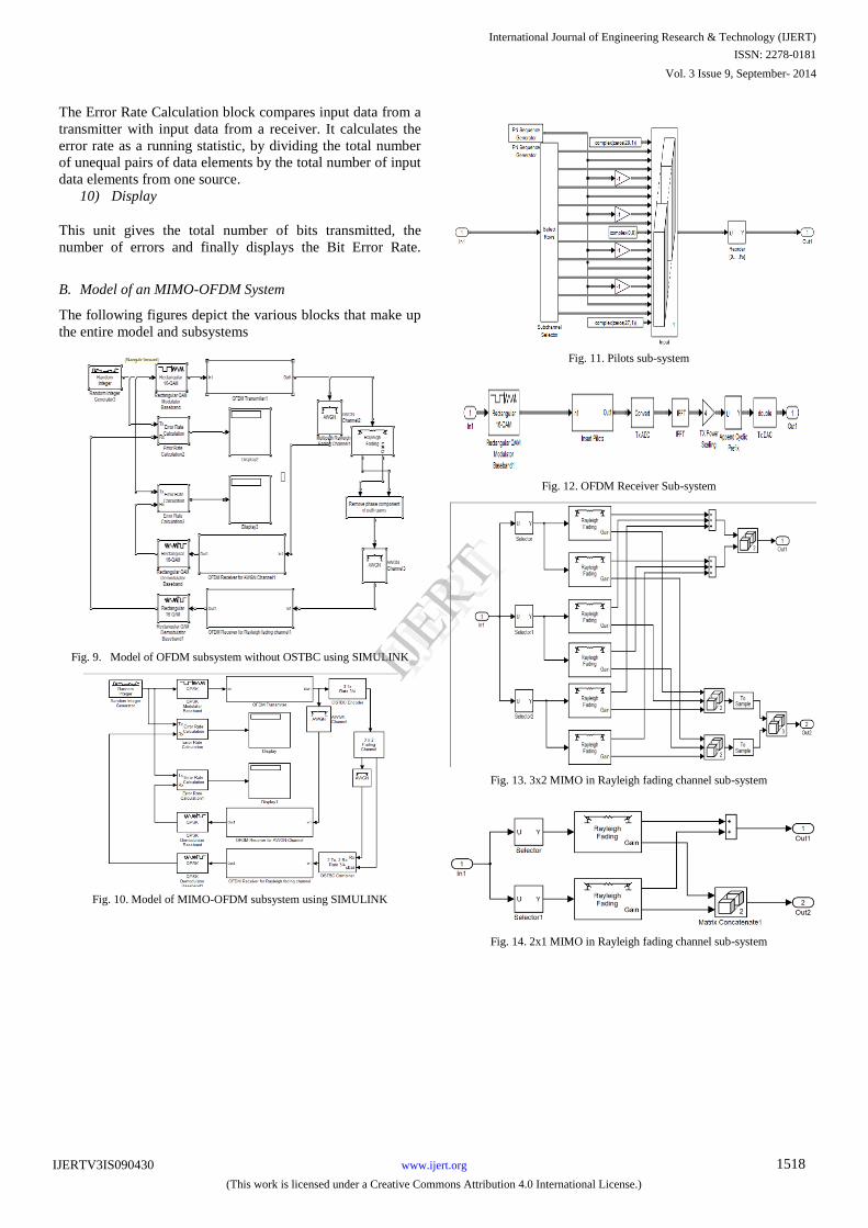
B. Model of an MIMO-OFDM System
The following figures depict the various blocks that make up
the entire model and subsystems
Fig. 9. Model of OFDM subsystem without OSTBC using SIMULINK
Fig. 10. Model of MIMO-OFDM subsystem using SIMULINK
Fig. 11. Pilots sub-system
Fig. 12. OFDM Receiver Sub-system
Fig. 13. 3x2 MIMO in Rayleigh fading channel sub-system
Fig. 14. 2x1 MIMO in Rayleigh fading channel sub-system
International Journal of Engineering Research & Technology (IJERT)
IJERT
IJERT
ISSN: 2278-0181
www.ijert.orgIJERTV3IS090430
(This work is licensed under a Creative Commons Attribution 4.0 International License.)
Vol. 3 Issue 9, September- 2014
1518

C. Simulation Environment
The following are the parameters of the Modelled OFDM
system.
TABLE I. PARAMETERS OF THE MODELLED MIMO-OFDM
SYSTEM
Parameters Values
Data Rates 1 Mbps
Modulation QPSK, 16 QAM and 64 QAM
FFT Size 256 with 200 sub-carriers uses, 192 for data and
8 pilots
FFT Period Also called symbol period, 256 μs
Guard Duration 1/16 of symbol time, 16 μs
Symbol Time 192 μs
Channel AWGN and Rayleigh Fading
Maximum Doppler
frequency 0.01Hz
Channel input signal
power 1W
D. Simulation Steps
Various blocks and sub-systems that make up the whole
MIMO-OFDM system were connected as shown in figs.
8 - 13.
First the model of fig. 8 was implemented.
The functional block parameters for the constituting
blocks were set.
For a given modulation/demodulation blocks pair the
SNR was set to 0 from AWGN channel functional
parameter blocks.
The simulation was run for 1 second.
The total bit transferred, numbers of bits in error as well
as the BER were taken from the display block of the
entire model.
For the same modulation/demodulation blocks pair the
SNR was varied from 0 to 30 in step of 2, run for I
second each time and the result from the display taken
for each step.
The steps described above were repeated for the two
other modulation/demodulation blocks pair.
The implementation of the MIMO-OFDM (fig. 9) is
similar to that of fig. 8
IX. RESULTS OF THE SIMULATION
Fig. 15. BER against SNR in AWGN channel
Fig. 14 reveals that the performance of the OFDM system in
AWGN channel improves (in terms of BER) with increasing
SNR. From the figure it is clear that QPSK has the best
performance when the SNR is less 6dB in comparison to 16-
QAM and 64-QAM beyond which 16-QAM performs best.
Also the BER for both 16-QAM and 64- QAM is very close
and becomes even closer as the SNR increases and
approaching 0 value for SNR level of close to 20dB. This is
somewhere around 22dB for QPSK.
To achieve a BER of 0.001, the SNR value attained shall be
close to 17dB for both 16-QAM and 64-QAM and
around19dB for QPSK.
Fig. 16. BER against SNR in Rayleigh fading channel
From fig. 15 above the performance of the system in
Rayleigh fading channel is low when compared to that of fig.
14. QPSK performs best in this channel at all SNR levels and
0 5 10 15 20 25 3010
-6
10-5
10-4
10-3
10-2
10-1
100
BER against SNR for different modulation schemes in AWGN Channel
SNR (dB)
BE
R
QPSK
16-QAM64-QAM
0 5 10 15 20 25 30
10-2
10-1
100BER against SNR for different modulation schemes in Rayleigh Fading Channel
SNR (dB)
BE
R
QPSK16-QAM
64-QAM
International Journal of Engineering Research & Technology (IJERT)
IJERT
IJERT
ISSN: 2278-0181
www.ijert.orgIJERTV3IS090430
(This work is licensed under a Creative Commons Attribution 4.0 International License.)
Vol. 3 Issue 9, September- 2014
1519
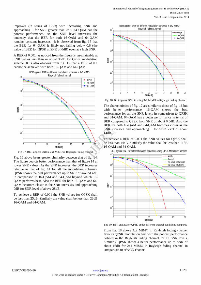
improves (in terms of BER) with increasing SNR and
approaching 0 for SNR greater than 0dB. 64-QAM has the
poorest performance. As the SNR level increases the
tendency that the BER for both 16-QAM and 64-QAM
remains constant increases. It is observed from fig. 15 that
the BER for 64-QAM is likely not falling below 0.6 (the
value of BER for QPSK at SNR of 0dB) even at a high SNR.
A BER of 0.001, as noticed from the figure is un-attainable at
SNR values less than or equal 30dB for QPSK modulation
scheme. It is also obvious from fig. 15 that a BER of 0.1
cannot be achieved with both 16-QAM and 64-QAM.
Fig. 17. BER against SNR in 2x1 MIMO in Rayleigh Fading channel
Fig. 16 above bears greater similarity between that of fig. 14.
The figure depicts better performance than that of figure 14 at
lower SNR values. As the SNR increases, the BER increases
relative to that of fig. 14 for all the modulation schemes.
QPSK shows the best performance up to SNR of around 4dB
in comparison to 16-QAM and 64-QAM beyond which 16-
QAM performs best. Also the BER for both 16-QAM and 64-
QAM becomes closer as the SNR increases and approaching
0dB for SNR level of above 28dB.
To achieve a BER of 0.001 the SNR values for QPSK shall
be less than 25dB. Similarly the value shall be less than 23dB
16-QAM and 64-QAM.
Fig. 18. BER against SNR in using 3x2 MIMO in Rayleigh Fading channel
The characteristics of fig. 17 are similar to those of fig. 16 but
with better performance. 16-QAM shows the best
performance for all the SNR levels in comparison to QPSK
and 64-QAM. 64-QAM has a better performance in terms of
BER compared to QPSK from SNR of about 0.5dB. Also the
BER for both 16-QAM and 64-QAM becomes closer as the
SNR increases and approaching 0 for SNR level of about
14dB.
To achieve a BER of 0.001 the SNR values for QPSK shall
be less than 14dB. Similarly the value shall be less than 11dB
16-QAM and 64-QAM.
Fig. 19. BER against for QPSK under different channel conditions compared
From fig. 18 above 3x2 MIMO in Rayleigh fading channel
favours QPSK modulation best with the poorest performance
noticed in the Rayleigh fading channel for all SNR levels.
Similarly QPSK shows a better performance up to SNR of
about 16dB for 2x1 MIMO in Rayleigh fading channel in
comparison to AWGN channel.
0 5 10 15 20 25 30
10-4
10-3
10-2
10-1
100
SNR (dB)
BE
R
QPSK
16-QAM64-QAM
BER against SNR for different modulation schemes in 2x1 MIMORayleigh fading Channel
0 2 4 6 8 10 12 14 16 18 20
10-5
10-4
10-3
10-2
10-1
100
SNR (dB)
BE
R
QPSK16-QAM
64-QAM
BER against SNR for different modulation schemes in 3x2 MIMORayleigh fading Channel
0 5 10 15 20 25 30
10-5
10-4
10-3
10-2
10-1
100
SNR (dB)
BE
R
AWGN
Rayleigh
2x1 MIMO (in Rayleigh)
3x2 MIMO (Rayleigh)
BER against SNR for different channel conditions using QPSK Modulation scheme
International Journal of Engineering Research & Technology (IJERT)
IJERT
IJERT
ISSN: 2278-0181
www.ijert.orgIJERTV3IS090430
(This work is licensed under a Creative Commons Attribution 4.0 International License.)
Vol. 3 Issue 9, September- 2014
1520
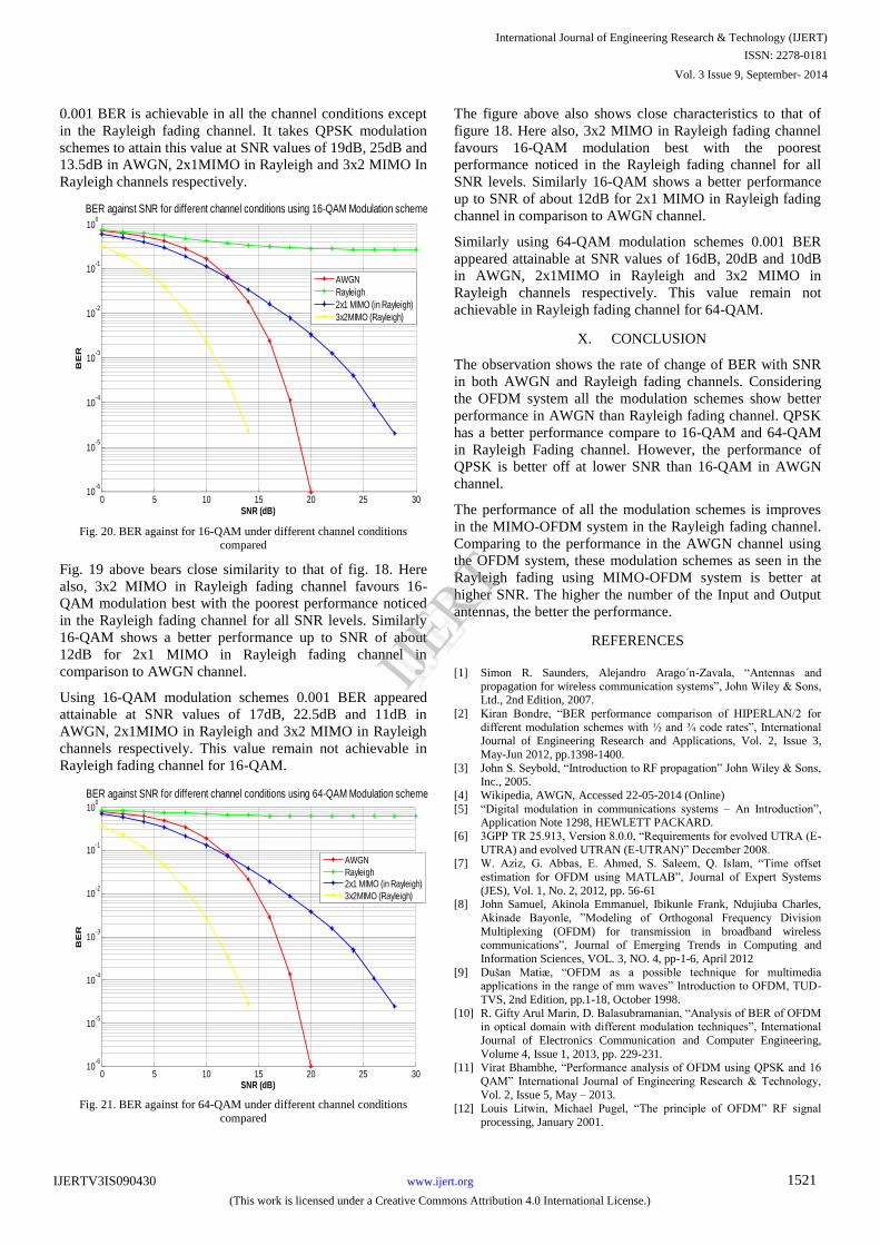
0.001 BER is achievable in all the channel conditions except
in the Rayleigh fading channel. It takes QPSK modulation
schemes to attain this value at SNR values of 19dB, 25dB and
13.5dB in AWGN, 2x1MIMO in Rayleigh and 3x2 MIMO In
Rayleigh channels respectively.
Fig. 20. BER against for 16-QAM under different channel conditions
compared
Fig. 19 above bears close similarity to that of fig. 18. Here
also, 3x2 MIMO in Rayleigh fading channel favours 16-
QAM modulation best with the poorest performance noticed
in the Rayleigh fading channel for all SNR levels. Similarly
16-QAM shows a better performance up to SNR of about
12dB for 2x1 MIMO in Rayleigh fading channel in
comparison to AWGN channel.
Using 16-QAM modulation schemes 0.001 BER appeared
attainable at SNR values of 17dB, 22.5dB and 11dB in
AWGN, 2x1MIMO in Rayleigh and 3x2 MIMO in Rayleigh
channels respectively. This value remain not achievable in
Rayleigh fading channel for 16-QAM.
Fig. 21. BER against for 64-QAM under different channel conditions
compared
The figure above also shows close characteristics to that of
figure 18. Here also, 3x2 MIMO in Rayleigh fading channel
favours 16-QAM modulation best with the poorest
performance noticed in the Rayleigh fading channel for all
SNR levels. Similarly 16-QAM shows a better performance
up to SNR of about 12dB for 2x1 MIMO in Rayleigh fading
channel in comparison to AWGN channel.
Similarly using 64-QAM modulation schemes 0.001 BER
appeared attainable at SNR values of 16dB, 20dB and 10dB
in AWGN, 2x1MIMO in Rayleigh and 3x2 MIMO in
Rayleigh channels respectively. This value remain not
achievable in Rayleigh fading channel for 64-QAM.
X. CONCLUSION
The observation shows the rate of change of BER with SNR
in both AWGN and Rayleigh fading channels. Considering
the OFDM system all the modulation schemes show better
performance in AWGN than Rayleigh fading channel. QPSK
has a better performance compare to 16-QAM and 64-QAM
in Rayleigh Fading channel. However, the performance of
QPSK is better off at lower SNR than 16-QAM in AWGN
channel.
The performance of all the modulation schemes is improves
in the MIMO-OFDM system in the Rayleigh fading channel.
Comparing to the performance in the AWGN channel using
the OFDM system, these modulation schemes as seen in the
Rayleigh fading using MIMO-OFDM system is better at
higher SNR. The higher the number of the Input and Output
antennas, the better the performance.
REFERENCES
[1] Simon R. Saunders, Alejandro Arago´n-Zavala, “Antennas and
propagation for wireless communication systems”, John Wiley & Sons, Ltd., 2nd Edition, 2007.
[2] Kiran Bondre, “BER performance comparison of HIPERLAN/2 for
different modulation schemes with ½ and ¾ code rates”, International Journal of Engineering Research and Applications, Vol. 2, Issue 3,
May-Jun 2012, pp.1398-1400.
[3] John S. Seybold, “Introduction to RF propagation” John Wiley & Sons, Inc., 2005.
[4] Wikipedia, AWGN, Accessed 22-05-2014 (Online)
[5] “Digital modulation in communications systems – An Introduction”, Application Note 1298, HEWLETT PACKARD.
[6] 3GPP TR 25.913, Version 8.0.0, “Requirements for evolved UTRA (E-
UTRA) and evolved UTRAN (E-UTRAN)” December 2008.
[7] W. Aziz, G. Abbas, E. Ahmed, S. Saleem, Q. Islam, “Time offset
estimation for OFDM using MATLAB”, Journal of Expert Systems
(JES), Vol. 1, No. 2, 2012, pp. 56-61 [8] John Samuel, Akinola Emmanuel, Ibikunle Frank, Ndujiuba Charles,
Akinade Bayonle, ”Modeling of Orthogonal Frequency Division
Multiplexing (OFDM) for transmission in broadband wireless communications”, Journal of Emerging Trends in Computing and
Information Sciences, VOL. 3, NO. 4, pp-1-6, April 2012
[9] Dušan Matiæ, “OFDM as a possible technique for multimedia applications in the range of mm waves” Introduction to OFDM, TUD-
TVS, 2nd Edition, pp.1-18, October 1998.
[10] R. Gifty Arul Marin, D. Balasubramanian, “Analysis of BER of OFDM in optical domain with different modulation techniques”, International
Journal of Electronics Communication and Computer Engineering,
Volume 4, Issue 1, 2013, pp. 229-231. [11] Virat Bhambhe, “Performance analysis of OFDM using QPSK and 16
QAM” International Journal of Engineering Research & Technology,
Vol. 2, Issue 5, May – 2013.
[12] Louis Litwin, Michael Pugel, “The principle of OFDM” RF signal
processing, January 2001.
0 5 10 15 20 25 3010
-6
10-5
10-4
10-3
10-2
10-1
100
SNR (dB)
BE
R
AWGN
Rayleigh
2x1 MIMO (in Rayleigh)
3x2MIMO (Rayleigh)
BER against SNR for different channel conditions using 16-QAM Modulation scheme
0 5 10 15 20 25 3010
-6
10-5
10-4
10-3
10-2
10-1
100
SNR (dB)
BE
R
AWGN
Rayleigh2x1 MIMO (in Rayleigh)
3x2MIMO (Rayleigh)
BER against SNR for different channel conditions using 64-QAM Modulation scheme
International Journal of Engineering Research & Technology (IJERT)
IJERT
IJERT
ISSN: 2278-0181
www.ijert.orgIJERTV3IS090430
(This work is licensed under a Creative Commons Attribution 4.0 International License.)
Vol. 3 Issue 9, September- 2014
1521

[13] Hermann Lipfert., “MIMO OFDM (Space Time Coding-Spatial
Multiplexing increasing performance and spectral efficiency in wireless systems)” Institut Fur Rundfunktechnik, August 2007.
[14] C.Nithiya, R.Rani kowsalya, M.Prabakaran, “Error control and
performance analysis of MIMO-OFDM over fading Channels”, IOSR Journal of Electronics and Communication Engineering (IOSR-JECE),
Volume 6, Issue 4, pp 12-18, May - June 2013.
[15] “All about modulation- Part I”, Inuitive Guide to Principles of Communication, www.complextoreal.com.
[16] Harjot Kaur, Bindiya Jain, Amit Verma, “Comparative performance
analysis of M-ary PSK modulation schemes using Simulink”, International Journal of Electronics & Communication Technology,
Vol. 2, Issue 3, Sept. 2011, pp. 204-209.
[17] Simulink Product Description, R2012a. [18] Arpita Mishra, Stuti Rastogi, Ritu Saxena, Pankaj Sharma, Sachin
Kumar, “Performance analysis of MB-OFDM system with QPSK and
QAM for wireless communication”, International Journal of Advanced Research in Computer and Communication Engineering, Vol. 2, Issue
2, February 2013.
[19] Priyanka Mehra, Rashmi Pant, “Throughput analysis of mobile WiMax under Rician fading channel”, International Journal for Advance
Research in Engineering and Technology, Vol. 1, Issue III, April 2013,
pp. 16-19. [20] Abhijyoti Ghosh et al., “Comparative BER performance of M-ary
QAM-OFDM system in AWGN & multipath fading channel”
International Journal on Computer Science and Engineering (IJCSE), Vol. 4 No. 06, June 2012.
International Journal of Engineering Research & Technology (IJERT)
IJERT
IJERT
ISSN: 2278-0181
www.ijert.orgIJERTV3IS090430
(This work is licensed under a Creative Commons Attribution 4.0 International License.)
Vol. 3 Issue 9, September- 2014
1522


![Near-Optimal MIMO Solutions in WiBro/WiFi/B3G ...mobile.snu.ac.kr/mcl_list/papers/journal/treview200506_sjkim_hjkim... · proposed by Qualcomm [4]. The MIMO WLAN uses OFDM modulation](https://img.dokumen.tips/doc/110x75/600e98cdc73d4a4ce74e5619/near-optimal-mimo-solutions-in-wibrowifib3g-proposed-by-qualcomm-4-the.jpg)


![Hard Decision-Based PWM for MIMO-OFDM Radar · 2. MIMO-OFDM Radar Signal Model-Based PWM 2.1. MIMO-OFDM Radar Systems Structure In [1], OFDM technique has the advantage of combating](https://img.dokumen.tips/doc/110x75/5e6a685a5002aa073940e3bf/hard-decision-based-pwm-for-mimo-ofdm-radar-2-mimo-ofdm-radar-signal-model-based.jpg)