Embed Size (px)
Citation preview

'.
.
*.
_.
OYSTER CREEK NUCLEAR STATION
REEVALUATION OF SAFE 1Y-RELATED00NCRETE MASONRY WALLSNRC IE BULLETIN 80-11
'IR No. 019Rev. 0
.
PROJECT NO: B/A 402240
hdh5M N w raORS
vATE os w nAPPROVALS: .
F sy?. |.. OfSEf
7" T 284B407310379 840726!
PDR ADOCK 05000'
dn\w- ,-VICE PRESIDENT DATETECIINICAL FUNCTIONS
,
(SIGNIFICANT IMPACT REVIEN)|
|

-. .,
i,
,
* |
"""'"'" - I' |
Neler T.R. No. 019TITLE O.C.N.S. - Reevaluation of Safety Relateo Concrete
Masonry Walls NRC I.E. Bulletin 80-11
REV SUMMARY OF CHANGE APPROVAL DATE
-fj,',, [ ' g c,7, g y'0~ This document replaces Topical Report with same gtitle, dated April 12, 1981 and TDR No. 242 Rev.0 7, 2fhUfwith same title. 1 f-
.
|
. AOC00036 7 82

o,
.
O
T.R. No. 019Page 2 of 7
ABSTRACT
)- --The purpose of this reevaluation is to determine the structural adequacyof the concrete masonry walls as required by the NRC IE Bulletin 80-11.
The analysis was perfonned using the ANSYS Computer Program to detenninethe frequency and resultant stresses in the block walls.
The results of the stress analysis indicate that all walls are qualified,except four walls to be analyzed later and the walls preempted bymodifications.
The recommended boundary and additional supports must be provided.
,
.
1
<
e
I |
e--- - w y - -- ,y- .we..--w , -,---- - - --ca- , , - - , - -,, .-.-, , -.r-,*w-,= e- *

.
'.
T.R. No. 019Page 3 of 7 l
.
.-
!
TABLE OF CONTENTS
Section Title Page No.
Abstract 2- _
1.0 Introduction 4
2.0 Status of Reanalysis and Modification 4
3.0 Me thods 5
4.0 Results 5
5.0 Conclusions 6
6.0 Recommendations 6
7.0 References 7
Appendices
1. Status of Wall Affected by I.E.-'
Bulletin 80-11 - 2 pages
2. Wall supports to be provided asa result of stress analysis - 1 page
3. Summary of Results - 31 pages
TOTAL EFFECTIVE PAGES OF THIS REPORT: 41
i
,
!-|
|
|
, r - - - , -- . , .- -,- ,-, , . , . , . . , , . . , - - , - - , - - , - .,e-- - -,

'
.
.
T.R. No. 019Page 4 of 7
.,
1.0 INTRODUCTION
The purpose of the reevaluation is to determine the structuraladequacy of the concrete masonry walls as required by the NRC IEBulletin 80-11.,
The reevaluation shall detemine whether the walls will performtheir intended function under all postulated loads and load
-~ combinations specified in the " Criteria for the Reevaluation ofConcrete Masonry Walls", Enclosure 2 to Reference 11 which isconsistent with the requirements outlined in item 2b of the Bulletin.
2.0 STATUS OF REANALYSIS AND MODIFICATION
- In the initial report (Reference 10) 47 walls have been identifiedas safety related walls to be reanalyzed. Thereafter, Wall No. 36has been incorporated in Wall No. 42. Consequently, there are 46safety related walls (See Appednix 1).
General arrangement and configuration of these walls is shown inEnclosures 4 and 5 to Reference 11.
- It was detemined that minor preemptive modifications to 20selected walls would remove the potential missile hazard to thevital systems and would preclude further reanalysis. The wallsincluded in this group are wall numbers: 1, 3, 4, 9, 10, 11, 12,13,14,16, 34, 35, 37, 38, 39, 40, 41, 42, 46 and 47.
- Wall No. 2 inside the Control Room has been removed from the scopeof the stress analysis due to the difficulty of providing theneeded supports. A net type vertical unistrut barrier wasprovided to insure that the wall can not fall onto the controlpanels (Reference 5).
- Wall No. 21 has been covered by consequence failure analysis andexcluded from stress analysis. The failure of Wall No. 21 willnot jeopardize the plant from a safe shutdown (Ref.13). Thiswall will be completely removed during the next refueling outage(Cycle 11).
j
I'- Wall No's. 31, 32, 33, and 45 which are covered by the consequence
failure analysis will be reanalyzed in the future as a combinationmodel. The failure of these walls will not jeopardize the plantfrom a safe shut down (Ref.13).;
- The remaining Wall Numbers 5, 6, 7, 8, 15, 17, 18, 19, 20, 22, 23,! 24, 25, 26, 27, 28, 29, 30, 43 and 44 have been stress analyzed.
Among the twenty walls, six of them (5, 6, 7, 25, 26, 27) do notneed modification. Twelve of them (8,15,17,18,19, 20, 24, 28,29, 30, 43, 44) will be modified during the cycle 11 refuelingoutage. These walls are also consequence - analyzed and the'
failure of them'will not endanger the plant from a safe shut down.( Ref 13. ) . The deferment of modification of these walls have beenapproved by the NRC (Ref.14),
t
. . . . . - . . ..,-. -- - , - . . - , - , , - , , , , . , , - - - - . _ - . - . . . . , . - -- - -=
'
.
T.R. No. 019 ,.
Page 5 of 7 |
..
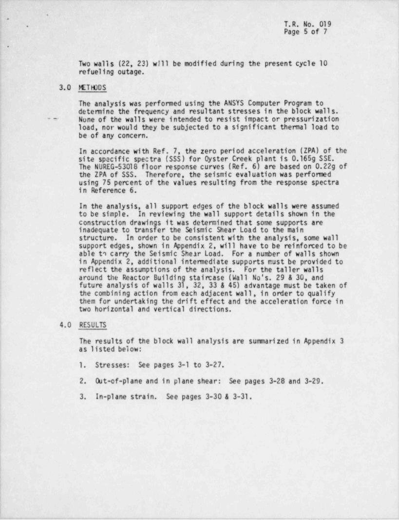
Two walls (22, 23) will be modified during the present cycle 10refueling outage.
!3.0 METHODS
The analysis was performed using the ANSYS Computer Program todetermine the frequency and resultant stresses in the block walls.
- -- None of the walls were intended to resist impact or pressurizationload, nor would they be subjected to a significant thermal load tobe of any concern.
In accordance with Ref. 7, the zero period acceleration (ZPA) of thesite specific spectra (SSS) for Dyster Creek plant is 0.165g SSE.The NUREG-53018 floor response curves (Ref. 6) are based on 0.22g ofthe ZPA of SSS. Therefore, the seismic evaluation was performedusing 75 percent of the values resulting from the response spectrain Fhference 6.
In the analysis, all support edges of the block walls were assumedto be simple. In reviewing the wall support details shown in theconstruction drawings it was determined that some supports areinadequate to transfer the Seismic Shear Load to the mainstructure. In order to be consistent with the analysis, some wallsupport edges, shown in Appendix 2, will have to be reinforced to beable to carry the Seismic Shear Load. For a number of walls shownin Appendix 2, additional intermediate supports cust be provided toreflect the assumptions of the analysis. For the taller wallsaround the Reactor Building staircase (Wall No's. 29 & 30, andfuture analysis of walls 31, 32, 33 & 45) advantage must be taken ofthe combining action from each adjacent wall, in order to qualifythem for undertaking the drift effect and the acceleration force intwo horizontal and vertical directions.
4.0 RESULTS
The results of the block wall analysis are summarized in Appendix 3as listed below:
1. Stresses: See pages 3-1 to 3-27.
2. Out-of-plane and in plane shear: See pages 3-28 and 3-29.
3. In-plane strain. See pages 3-30 & 3-31.
,
|t
|
i_ _ .- _ _ . . . . . _ . . _ . .-__ ._, ..m.. _ . . . _ . . , _ , _ _ . , . . . _ _ _ _ . _ . . _ . _ . . _ . - _ . - _ .-
.--
'.
T.R. Ns. 019.
Page 6 of 7
.
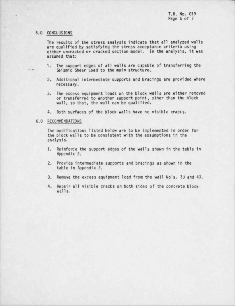
5.0 CONCLUSIONS I
The results of the stress analysis indicate that all analyzed wallsare qualified by satisfying the stress acceptance criteria usingeither uncracked or cracked section model. In the analysis, it wasassumed that:
1. The support edges of all walls are capable of transferring the' - -- Seismic Shear Load to the main structure.
2. Additional intermediate supports and bracings are provided wherenecessa ry.
3. The excess equipment loads on the block walls are either removedor transferred to another support point, other than the blockwall, so that, the wall can be qualified.
4. Both surfaces of the block walls have no visible cracks.
6.0 RECOMMENDATIONS
The modifications listed below are to be implemented in order for,
the block walls to be consistent with the assumptions in theanalysis.
1. Reinforce the support edges of the walls shown in the table inAppendix 2.
2. Provide intermediate supports and bracings as shown in thetable in Appendix 2.
3. Remove the excess equipment load from the wall No's. 33 and 43.
4. Repair all visible cracks on both sides of the concrete blockwalls.
|
|
|:
!
!
!-. . -- . . . . . . _ . _ _ . . , . _ . . . , _ _ . _ _ - - . . , _ . - - , _ , , , - , _ _ - , _ , , _ . _ _ .-- , - _

_
_ _ -__ _-___ --
'.
.
T.R. No. 019rPage 7 of 7.
7.0 REFERENCES
1. ACI 531-79 "Buf1 ding Code Requirements for Concrete MasonryStructures".
2. Burns & Roe, Inc. , Technical Specification No. 45, Section 4A.7_ _ (See Appendix 2 Enclosure 9).
3. ASTM-C90-75 " Hollow Load-Bearing Concrete Masonry Units".
4. Burns & Roe, Inc. , Drawing No. 4514-3 " Misc. Plans Sections andDetails (Masonry)".
5. Impe11 Calculation No's. 0370-055-008, 0370-055-009,0370-055-010, 0370-055-011.
6. NUREG/CR-1981-0CRL-53018 RD, RH - Seismic Review of Oyster CreekNuclear Power Plant as Part of the Systematic Evaluation Program.
7. U.S. NRC Letter No. LS05-06-068, dated June 17, 1981: SiteSpecific Ground Response Spectra for SEP Plants located in theEastern United States.
8. GPUN Calculation No.1302X-322C-A06.
9. GPUN Calculation No. C-1302-150-5320-005.
10. JCPL/GPU Letter to NRC, dated September 19, 1980.
11. JCPL/GPU Letter to NRC, dated November 14, 1980.
12. JCPL/GPU Letter to NRC, dated April 30, 1981.
13. Impe11 Report No. 02-0370-1132, " Masonry Wall FailureConsequence Analysis", Rev.1, May 1,1984 and Impell Report No.02-0370-1139, "0C-Containment Spray System Assessment Associatedwith the Postulated Collapse Stairwell Masonry Walls", Oct.1983.
14. NRC Letter Docket No. 50-219, LS05-84-03-037 datedMarch 27, 1984, Subject: Licensee Request to DeferModifications of Some of the Masonry Walls (I.E. Bulletin 80-11)Dyster Creek Nuclear Generating Station.
>
+ ---.-,,.r- ,-y,- . - ~ , - - - , - ,,---.-#. 3,-- -- -, e,,vvn,- - , , - .,,.-,,-,---. ~ nw-w..,,w w w#,- ,---%.----,w-,w,----p3-,.,ww- .ec...-.-,-em ,

-
9
9 l
,
!i
.
e ehe
APPENDIGS
1,
It
- -- - _ - ,_ " "~ ~ ~ . ~ , . _ , , _ _ ,

*.
,
*
|
.
- _.
APPENDIX 1
STA7US OF WALIS Arrrrrw BY
IE BULIEPLN 80-11

*.
*s
.
.
STATUS OF WALLS AFFECTED BV !.E.B. #80-11
QUALIFYING MOO!FICATION
_. METH00 STATUS
Modt fication Modt ficationto be comple- to be comple.m2 U No Modtfi- Modtff. REMARKSia g tad prior to ted during
gM QC wg cation cation Restart during the nextE Needed Completedi Re-Fueling Re-FuelingWALL
, g gW *Bsa
N0s. 1:! Outage Cycle Outage Cycle''' 10 11
1 X X
A not type vertical2 x y untstrut barrier will
be provided to insurethe wall can only fallaway from the controlpanels. (Ref. 5)
3 x X
4 X X
5 K X
6 X X
7 X X
8 X X
9 X X
10 X X
11 X X
12 X X
13 X X
X14 X +
15 X X
16 X X
17 I X
18 X X
19 X X
20 X Xwmswu a namte4 8t f f/Jfd4f (tW //)
22 X X
23 X X*
24 X X
.
! 1 -1
. . , _ _ . _ _ _ - _ . . .. - .- ..

*.
,
.
.
STATUS OF WALLS AFFECTED BY 1.E.8. #80-11|
QUALIFYING MODIFICATION
METHOD STATUS.
No Modiff- Modi f t- Modifica.fon Modification' ~
cation cation to be comple- to be comple-Needed Completed ted prior to ted during REMARKS'
. ca $12 g Restart during the nextRe-Fyeling Re-Fueling
af k! If g! g outage Cycle Outage CycleWALL "n M ow
3 g 10 11N05. *
25 I X,
26 X Xj
27 X X
28 X X
29 X X
30 X X
31 X X Will be re-analyzedby a combined model
32 X X of walls no. 31, 32,
33 X X 33 and 45.3 0 Setssic applies
34 X X
35 X X'
37 X X
38 X X
39 X X
40 X X
41 X X
42 X X
43 X X
44 I X
; 45 X X See reaarss for wellnos. 31, 32 and 33.
46 X X
47 X X
.
e
e
r
1-2
l

6'
-,
e
O
4
APPENDIX 2- --
WAIL SUPPORTS TO BE PROVIDED
AS RESULT OF STRESS ANALYSIS
_ . _ -_-____ _ -_.

*.
.
WALL SUPPORTS TO BE PROVIDED AS RESULT OF STRESS ANALYSIS
e a 9 Su m t RemarksWall No. p.N E S W
5 No modification is needed
6 No modification is needed--
t- 7 No modification is needed_
-- 8 yes Provide intemediate bracing
15 yes Provide intemediate bracing
17 yes yes
18 yes yes- . . - - - . - - - - -
| Provide Intemediate Bracing19 yes_
20 yes Provide Intemediate BracingExcluded Trctri3flGBs Efiilysis. TlilTwEriiffl~ bh~
21 removed during cyc.11 outage. tb nrrlifimHen is mded..
22 yes yer* | es * Strengthen east edge with unistruty
23 yes yes Provide steel framing & bracing
24-1 yes yes yes Provide steel framing a bracing. . _ _ . .. __ _
24-2 yes
25 No modification is needed j_
26 No modification is needed
27 No modification is needed_ = . . . - . - - - - - . .
28 yes
29 yes yes Provide intem. framing (L-Shape) & racing |i
30 yes yes Provide interm framing (L-Shape)'
31 To be reanalyzed'
. . . _ _ _ .
32 To be reanaly:ed
33 To be reanalyzed_
43 yes Provide add'1. support for equipment.
| 44 yes-
(
| 45 To be reanalyzed~
i
Note: For Wall No. 2 a net type vertical unistrut barrier will be provided
| to insure the wall can only fall away from the control panels.| 2-1
. - _ . , . , , -

-. _. _ - .-
..
.
.
.
APPENDIX 3- __
Sunnary of Results
t
i
4
I
i
f
i
w
|
|
!
>
9
,
!I
h

'-
.
* GENERAL NOTES FOR STRESS TABLES:
1. Wall No's. (2-1, 2-2, 2-3, 2-4) were removed from the scope of the"
stress analysis as explained in section 2 of .this report.
2. For Wall No's. 5, 6, 7, are qualified by one way cracked sectionmodel. The existing boundary supports are acceptable. No
modification is needed.
3. Wall No's. 29 and 30 have been reanalyzed as a combination L Shapemodel; 3-directional seismic fon:e was considered in this analysis.
,_
4. Wall No's. 31, 32, 33 and 45 will be reanalyzed as a combinationmodel; 3-directional seismic fon:e will be considered in the analysis.
5. Wall No's. 25, 26, 27 have been heavily reinforced with unistrut,through bolts and bracings on both faces. No modification isnecessary.
6. Wall No. 21 has been covered by consequence failure analysis and,
excluded from stress analysis. The failure of Wall No. 21 will notjeopardize the plant from a safe shutdown (Ref.13). This wall willbe completely removed during the next refueling outage (cycle ll).
7. Wall No. 42 has been preempted.
I
lJ
3-1|
. - . - _ . .. - --_ . . - _ .

'
.
*|
|1
GENERAL NOTES
Type of 1. All blocks are ASTM-C-90 hollow blockConstruction Walls that are reinforced have vertical rebar and
horizontal dur-o-wall as shown below.
Yertical: Rebar Fy= 40,000 psi__
Horizontal: Dur-0-Wall Fy= 70,000 psi( ASTM-A-82)
Frequency 1. All edge conditions are Simple-Supported.'
Range - Hz 2. For 3-Edge support, the edge that has not counted forhas been pointed out.
3. Additional supports have been noted.
ALLOWABLE STRESSES (psi).
Flexural Tensile Load Normal to Bed Jt Parallel to Bed JointStresses Combination RJnning Stack Running Stack1. Uncrecked Bond Bond Bond Bond
Section
a. Hollow OBE+DL 25 25 50-
Block SSE+DL 41.5 41.5 83 -
b. Hollow B1k. OBE+DL 50 40 75 -
Fully Grouted SSE+DL 83.5 67 125
2. CrackedSection Vertical Rebar Horizontal _D.ur-o-Wall
OBE+DL 20,000* 30,000,
SSE+DL 36,000* 63,000a. Steel__
b. ConcreteCompressive OBE+DL 396Stresses SSE+DL 1020
Out of PlaneShear Flex-Shear In Plane ShearStresses Running Stack Running Stack
Bond Bond Bond BondOBE+DL 38.1 f5.4 31 . 2 20.8SSE+DL 49.5 33.0 40.6 27.1
~~~ ~
Bond Stress OBE+0L 140SSE+DL 186
*Except walls 5, 6, 7, where rebar is A615 Grade 60: OBE+DL allowable 24,000SSE+DL allowable 54,000
3-2
. _ . _-. - --_ - _. __ _. _ _ _ - - _

* SLMERY OF RESULTS.
.
Turbine Building, Observation Room Enclosure,Iocation South Wall"
-
Floor Elev. 49'-8"
Dimensions of Height: 10 Ft 10 In. Thickness: 8 In.Model Width: 14 Ft 11 In.
Block: AS'IN-C-90 ( X) Running BondType ofConstruction M rtar: Type "M" ( ) Stacked Bond
(X ) Reinforced ( X) Other Fully crot+nd himk- - --
( ) Unreinforced-~
f X ) One Way(X ) Vertical Span 1 3.51 To 16.ss
Frequency ( ) Horizontal SpanRange - Hz(Uncracked ( X) 'No WaySection) ( X) 4-Edge Support 201 A To 24.77
( ) 3- Edga Support( ) Top, ( ) Side, Missing
ResponseAcceleration ( X ) One Way 1.52 g, ( ) Two Way: 0.40 g,(Uncracked (OBE) (OBE)
Section) 1.99 g, 0.76 g,(SSE) (SSE)
( X ) One Way:
Flexural Tensile ( X ) Normal to Bed Joint, 229.3 vs 50.0Stresses - psi (OBE+DL) (Allowable)(Uncrakced 299.0 vs 83.5Section) (SSE+DL) (Allowable)
*
( ) Parallel to Bed Joint, vs(OBE+DL) (Allowable)
vs(SSE+DL) (Allowab]e)
(X ) Two Way:(X ) Normal to Bed Joint, 34.5 vs 50.0s,
(OBE+DL) (Allowable)59.4 vs 83.5
(SSE+DL) (Allowable)(X ) Parallel to Bed Joint,
_ 18.4 vs 75.0(OBE+DL) (Allowable)
34.3 vs 125.0(SSE+DL) (Allowable)
Wall is c; cod for two way model. However, in order -Remarks not to i s' .ll the hori--**.1 bctmda;;y supporto, ow' Wall No' 5MXt gg pgjifftT.* d'** # # " * * *e
3-3
.

_ - .
''
Su m ARY OF RESULTS - (Cont'd.)',
~
(X) One WayFmpaency ( X ) Vertical Span 3.60 'Ib 4.41Range - Hz ( - ) Horizontal Span(CrackedSection) *
( ) 'No Way.( ) 4-Edge Support( ) 3-Edge Support Tb( ) Top, ( ) Side, Missing
. _.
Response ( X ) one Way: 0.47 o, ( ) Two Way: g,Acceleration- (CBE) (OBE)
(Cracked,
Section) 0.71 g, 9,
(SSE) (SSE)
f1'
) Norma ( ) parallel, to Bed Joint(Crac W f(Steel): 7.000 vs 24.000'
Section)(O BE+%) (Allowable)
25,670 vs 54,000~
(SSE+DL) (Allowable)
f(Conc.): -341.0 -396.0y,
( resim) (OBE+DL) (Allowable)- 51 5.0 vs -1020.0
(SSE+DL) (Allowable)
( ) Two Way:( ) Normal to Bed Joint
f(Steel) : vs(OBE+DL) (Allowable)
vs(SSE+DL) (Allowable)
f(Conc.) : vs(OBE+DL) (AlloA21e)
vs-
(SSE+DL) (Allowable)( ) Parallel to Bed Joint
f(Steel): vs(CBE+DL) (Allowable)'
vs
j. (SSE+DL) (Allowable)Remarks Wall is good for one w_y crec)*ed section.
I tb horizontal boundary Wall No. 5,
istrynrt in nanAnd
?'
| 3-4L i

SUMMARY OF RESULTS_..
*.
Turbine Building, Observation Room EnclosuraLocation South-E: int to Nbrth-ilest Wall Floor Elev. 49'-8"
.
1
Dimensions of Height: 10 Ft 10 In. Thickness: 8 In.Model Width: 7 Ft 6 In.
Block: AS7M-C-90 ( X) Running DondType ofConstruction Mortar: Type "M" ( ) Stacked Bond
( X) Reinforced ( X ) Other Fully crouted block---
( ) Unreinforced
f X) One way( x) Vertical Span 13.48 To 16.51
Frequency ( ) Horizontal SpanRange - Hz .
(Uncracked ( X) Two WaySection) ( X) 4-Edge Support 39.37 To 48.22
( ) 3- Edge Support~~
( ) Top, ( ) Side, Missing.~
Ac tion (X ) One Way 1.52 g, ( X) Two Way: 0.18 g,(Uncracked (OBE) (OBE)Section) 1 99 g, 0.35 g,
(ssF) (sse)(x ) One Way:
Flexural Tensile (x ) Normal to Bed Joint, 241.4 vs 50.0Stresses - psi (OB +DL) (Allowable)(Uncrakced 314.0 vs 83.5Section) (SSE+DL) (Allowable)
( ) Parallel to Bed Joint, vs(OBE+DL) (Allowable)
vs(SSE+DL) (Allowable)
___
(x ) Two Way:(n ) Normal to Bed Joint, 14.4 vs 50.0,
(OBE+DL) (Allowable)16.6 vs 83.5
(ESE+DL) (Allowable)( X ) Parallol to Bcd Joint, 11.8 ~ vs 75.0
(OBE+DL) (Allowable)14_7 vs 129.0
(SSE+DL) (Allowable)!!all is good for two way Iniel. However in
EMh26rr5$. deeSiSHtipk5 ISS $$$gunb.ryordernottoinstalltgenorizontalbRemarksu5$s Wall No: 68
. . .
3-5

- ,
'
SU194ARY OF RESULTS - (Cont'd.)*
'
|
\
( X ) One Way ]'
Frequency (X) Vertical Span 3.60 To 4.41 ,
Range - Hz ( ) Horizontal Span(CrackedSection) |
'
( ) 4-Edge Support( ) 3-Edge Support To( ) Top, ( ) Side, Missing
- -.
Response ( X ) One Way: 0.47 g, ( ) 'No Way: g,Acceleration (OBE) (OBE)
|
(CrackedSection) 0.71 g, 9,
(SSE) (SSE)
htre (X Norma ( ) parallel, to Bed Joint
f(Steel): 17.000 vs 24.000(OBE+DL) (Allowable)
25,670 vs 54,000(SSE+DL) (Allowable)
f(Conc.): -341.0 -396.0vs(OBE+DL) (Allowable)(Compression)-515.0 vs -1020.0
(SSE+DL) (Allowable)
( ) Two Way:( ) Normal to Bed Joint
f(Steel) : vs(OBE+DL) ( Allcraable)
:vs*'
(SSE+DL) (Allowable)
f(Conc.) : vs(OBE+DL) (Allowable) i
vs(SSE+DL) (Allowable)
( ) Parallel to Bed Jointf(Steel): vs
,
(ObE+DL) (Allowable) (
vs ,
(SSE+DL) (Allownblo)Remarks Wall is good for one we.*/ crccked section,
flo horizontal boundary Wall No. 6auvnet in nnutul
3-6,
m -_ _ _ _ _ . _ _ _ _ _ . _ _ _ _ . _ _ _ _ _ _ _ _ _ . _ _ _ _ _ _ _ _ _ _ _ _ _ _ _ _ _ . . _ _ _ . _ . . _

F
SUPNARY OF RESULTS.
.
.
Turbine Building, Observation Room EnclosureI m tion West Wall Floor Elev. 49'-8".
.
| Dimensions of Height: lg__ Ft in In. Thickness: 8 In.Model Width: 7 Ft o In.
.
Block: ASM-C-90 ( X ) Running DondType of; Construction Mortar: Type "M" ( ) Stacked Bond
I X) Reinforced ( X ) Other gou ca hiev k| e'*-
( ) Unreinforced:.
f X) One Way,
( X) Vertical Span 11.9A Tb 17.12 _ ,'
Frequency ( ) Horizontal SptnRange - Itz =
(Uncracked ( X) TW WaySection) ( X) 4-Edge Support 45.30 To 55.48
( ) 3- Edge Support__
( ) Top, ( ) Sido, Missing~
ResponseAcceleration (X ) One Way 1.52 g, ( X) Two Way: 0.18 g,(Uncracked (OBE) (OBE)Section) 1.99 g, _0.35 g,
I ice t acera
(X ) One Way:Flexural Tensilo (X ) Nomal to Bed Joint, 224.0 vs 50.0Stresses - psi (OBE+DL) (Allowable)(Uncrakced 291.7 vs 83.5Section) ' (SSE+DL) (Allowable)
( ) Parallel to Lod Joint, va(DBE+DL) (Allowable)
va(SSE+DL) (Allowable)
|( X ) 'No Way( X ) Normal to Bed Joint, 10.0 vs 50.0,
(OBE+DL) (Allowable)! 11.7 vs 83.5l (SSE+DL) (Allowable) || ( X ) Parallol to Dod Joint, ...59 vn 75.0
(OBE+DL) (Allowable) i
| 11.8 vs '25.0 1
I
| (SSE+DL) ( Al;,owable)Wall is good for 'No Way Modol. I!owever, in ordor
Re.Tarks not tn i.mtall the horizmtal tourdery suctorts, ono ,
way cracked section analysis was perfomed. Soo no::t Wall No: 7 :
rann f<r rnanita 1
3-7
_ . _ _ _ _ _ _ . - ___ --- _ _ _ _ _ _ _ - - _ _ _ _ _ _ _ _ _ _ _ _ _ _ _ _ _ _ _ _ _ _ _ - - - -

_
,_ . __
*
SUPMutY OF RESULTS - (Cont'd.),
- ,,,
;*
( X ) One WayFrequency ( X ) Vertical Span 3.60 To 4.41Range - Hz ( ) Horizontal Span(CrackedSection) -
( ) 'No Way( ) 4-Edge Supprt( ) 3-Edge Sin ort To( # Top, ( ) Side, Missing
- . ._
Response ( X ) One Way 0.47 g, ( ) Two Ways g,Acceleration (08E) N)(Cracked
g1 -9e 9'Section)
.
F 1 Ten 1 ( X ) One Way:( X ) Nomsl, ( ) parallel, to Bed Joint
(Cracked f(Steel): 7.cor vs 24.000'<
Section) (0BE+DLl (Allowable)25,670 vs 54,000
($$E+DL) (Allowable)
f(Conc.): -341.0 -396.0y,
( ressim) (OBE+DL) (Allowable)_ _-515 . 0 . vs -1020.0 t
(SSE+0L) (Allowable) |- ,
( ) 'Be Ways( ) Nomal to Bed Joint
f(Steel) : V8(OBE+DL) (Allowable) i
vsTSSE+DL) (Allowable)
f(Conc.) : vs(OBE+DL) (Allowable)
vs-
(SSE+DL) (Allowable)( ) Parallel to Bed Joint '
f(Steel): vs(OBE+DL) (Allowable)
vs
(SSE+DL) (Allownble)Remarks WIllisgoodforonew:yc:cchodsection.
Hn hnrivnntal boundary Wall tb. 7mu mrt 9 e eht i
3-8_ _ _ _ _ _ _ . _ _ . _ _ _ _ _ _ _ _ _ _ _ _ _ _ _ _ _ _ _ _ -

'
SLDNARY OF RESULTS*
O
Offico Building, Cable Tray Area, East Wall,Ixcation Intenndediate Section, Elev. 46'-6",
Dimensions of Height: 12 Ft 10 In. 'Itickness: 6 In.Model Width: 21 Ft 3 In.
..
g : neck: AS'IN-C-90 ( ) Running BondAstar: W "M" ( X ) Sucked Mtruction( ) Reinforced ( ) Other(;) Unreinforced
(X? %15.90 To 20.53(Xi '*ertical Spanw/interpgg,
( i !ortzontal SpanFrequencyRange - 112 -- --
(Uncrackod ( ) 'No WaySection) ( ) 4-Edge Sup crt 'Ib
( ) 3- Edge Support( ) Top, ( ) Side, Misting
__
ce ration ( X ) Ono Way 0. M g, ( ) M Way. g,(OBE) (OBE)(Uncracked
Section) 0.34 g, g,(SSE) MTl
( X ) Ono Way;( X) Nonnal to Bed Joint, 21.8 vs 25.0Flexural Tonsile
(OEC+DL) (Allowable) '
htresses - psi(Uncrakcod 40.2 41.5y,
Section) (SSE+DL) (Allowable)( ) Para 1101 to Bod Joint, va
(OBE+DL) (Allowable)vs :
'
(SSE+DL) (Allowable)
( ) Two Way: i
( ) florm1l to Bod Joint, vs '
(OLE +DL) (Allowable)vs
(SSE+DL) (Allowablo)( ) Parallel to Ikxl Joint,
.vs
(OLE +DL) (Allowablo)vs
(SSE+DL) (Allowablo)Wall in gotx1 for too way with interwxlinto
Remarks & top nup[ orts. g
3- 9 '
_ _ _ _ _ _ _ _ _ - - _ - - . _ _ _ _ _ _ _

--
,
::. : -,.
,' .
. SUMMRY CF RESULTS-,
'. f,
-
Off c^ Building, Monitor and Change Room,,
Location South Wall, Intermediate SectionElev. 46'-6"
Dimensions of Height: 13 Ft. 4 In. Thickness: 6 In.
Model Width: 15 Ft 10 In.1
Type oF , Block: ASIM-C-90 ( ) Running Bondmrtar: Type "M" ( X) Stacked BondConstruction( ) Reinforced ( ) Other
_ ( X) Unreinforced
0X) One Way( X) Vertical Span w/interm supports 24.90 To 32.15( ) Horizontal SpanFrequency
Range - Hz(Uncracked ( ) T w WaySection) ( ) 4-Edge Support To
( ) 3- Edge Support.(. ) Ibp, ( ) Side, Missing
Ach$ tion ( X) One Way 0.16 g, ( ) h Way- g,(OE) (OBE)(Uncracked
Section) 0.32 g, g,(ESE)
' (SSE)
( X) One Way:( X) Normal to Bed Joint, 5.6 vs 25.0
Flexural Tensile ,.
<,eE+DL) (Allowaale)Stresses - psi(Uncrakced 15.7 vs 41.5Section) (SSE+DL)' (Allowable)
'
( ) Parallel to Bed Joint, vs(OBE+DL)' (Allowable)
.
vs(SSE+DL) .(Allowable)
( ) T m Way:( ) Nomal to Bed Joint, vs
(OBE+DL) (Allowable),
vs-(SSE+DL) (Allowable)
( ) Parallel to Bed Joint, vs'(OBE+DL) (Allowable)
- vs(SSE+DL) (Allowable)
Wall is good .for one way with intem ediateRemarks & top supports,
_
Wall No: 15
'
3-|0
en- 1
se g--- w-c- g y-- - ~m y -7 y-3-

_ _ __.
,*SE141R.'( 0,QJq, il,Q*
-,. - . .
Locntion . Office Bldg. Bottory,Roon.South Wall, West Section'
'
Fl . El . 35 '-0"
.
11 0 , In. Thickness: 6 In.-
Di:nensions of Ilcight:7 ,_ Ft, Ft _11_ _ ,I n .Model Width:. __
.
(X) Running Bond |'
Ty'pc of Block: ASTM - C-90Coastruction Mortar: Type "M" ( ) Stacked Bond ;
iC) Reinforced ( ) Other _
(X) Unreinforced _ _ . ,
'
_.
Frequency (X) One Way 10.19 To 13 .,M _Range - Hz (X) Vertical Span(Uncracked ( ) Horir.ontal SpanSection) . X) Two Way( 15.22 To 19.65(X) 4-Edge Support
( ).3-Edge Support( ) Top, ( ) Side, Missing
Response (X) One Way: 0.22 g, ( ) Two Way: _ 0.34 g,
Acceleration (QBE ) (OBE )
0.50 g'(Uncracked 0.41 g*Section) (SSE) (SSE )
. Flexural Tensile ( ) One Way:Stresses - psi ) N ma t Bed Joint, vs .
I(Uncracked (OBE+DL) (A Houtu b)Section) 68.3 vs 41.5
,(SSE+DL) (Allowable)
( ) Parallell to Bed Joint, vs'
(OBE+DL) (Alloua' ole)vs
(SSE+DL) (Allowp.ble)}(X) Two Way:
25.1 vs 25.0(X) Nonnal to Bed Joint,(OBE+DL) (A1lowab1c)
41.538.7 v3
(SSE+0L) (Allowable)50.019.1 vs(% ) Parallel to Bed Joint,
(OBE+DL) (A1louahic)83.027.0 vs
(SSE+DL) (A1lowable). _ _ . . .1
0.K. for Two-Way Model with top cnd ,
Remarks vertical edge cupM ts. Wall No. 17 !!
.: 1-a=--..
3- H
. _ _ . _ _ . . , _ . . . . _ , ._ -._...__ _ -_., _ , _ _ _ _ . - . _ . . , _ . - . , . . _ .

_ _ _ _ -.
. . . . _
*s
SultuRY OF RESULTS.,
,
Location '. Of fice Bldg. Battery RoomWest Wail, South Section,
F1. El . 35 '-0"
' Dimensions of licight: 11 Ft 0 In. Thickness : 6 , ,I n .
Modcl Width: T~~ ~ F C 5 In.--. .._..-. - - _ .
Ty'pc of Block: ASTM - C-90 (X ) Running 'sdad - *
Construction Mortar: Type "M" ( ) Stacked Hond ;I
( ) Reinforced ( ) Other(X) Unreinforced _,
|
lj
Frequency (X) One Way 10.23 To 13.21Range - Hz (X) Vertical Span _
(Uncracked ( ) Horizontal SpanSec tion) @) No Way 16.73 To 21.60(X) 4-Edge Support
( ) 3-Edge Support( ) Top, ( ) Sido, Missing
Responso (X) One Way: 0.22 g, (X) Two Way: 0 .13 _g ,
Acceleration (OBE) (OBE )
(Uncracked 0.41 0.60 p' 'b, *
Section) (SSE ) GSE)
Flexural Tensile (X) One Way:'
8#j (X) Normal to and Joint,'P vu__
d (OBE+DL) (A1Lovabie)Section) 65.2 41.5vs
(SSE+DL) (Allowabic),.
( ) Parallell to Bed Joint, vs _' ___
(OBE+DL) (Allowabic)
_______vs_ _____
(SSE+0L) (Allouable)(X) Two Way:
18.24 vs 2 5 . 0 __ _ _ _ __,(X) Norm.11 to Bed Joint,_(OBE+DL) (Allowabla)
_
36.4 41.5v3
(SSFADL) (Allowabid[16.30 50.0
____ v3(X) Parallel to Bed Joint,_ _ _(OBE+DL) (Allouabic)
,,,,,,
28.6 vs 83.0(SSE+DL) (Allowabic)
0.K. for Two-Way Model, with tcp rd .
ve dic2.1 edge sug,aorts. Wall No._18Remarks
_ _ . _ - _ _ _ = . -_.-
*4 3_32-

*
SU!HARY OF RFEULTS.
.-
Office Bldg. Elect, Tray RocnIocation North Wall*
Fl. El. 35'-0"
Dimensions of Height: 11 Ft 0 In. Thickness: 6 In.
Model Width: _10 Ft 6 In.
Block: AS'IM-C-90 ( ) Running BondType of Nrtar: W "M" ( X) SMed BondOonstruction( ) Reinforced ( ) Other( X) Unreinforced
( X ) One Way25.17 To 32.49( X ) Vertical Span w/intggge
( ) Horizontal SpanFrequencyRange - Hz(Uncracked ( ) Two WaySection) ( ) 4-Edge Support Tb
( ) 3- Edge Support( ) 'Ibp, ( ) Side, Missing
Ac tion ( X ) One Way 0.16 g, ( ) Two Way: g,(OBE) (OBE)(Uncracked
Section) 0.32 g, g,(SSE) (SSE)
( X ) One Way:I X ) Normal to Bed Joint, 11.6 vs 25.0Flexural Tensile
(OBE+DL) (Mlw@le)Stresses - psi(Uncrakced 24.4 vs 41 .5Section) (SSE+DL) (Allowable)
( ) Parallel to Bed Joint, vs(OBE+DL) (Allowable)
vs(SSE+DL) (Allowable)
( ) Two Way:( ) Normal to Bed Joint, vs
(OBE+DL) (Allowable)vs
(SSE+DL) (Allowable)( ) Parallel to Bed Joint, vs
(OBE+DL) (Allowable)vs
(SSE+DL) (Allowable)
Wall is good for one way with intermediateRemarks and top supports. Wall No: 19,
.
3-13
- - . - - - .- - .

'
SUMMARY OF RESULTS.
Office Bldg. Elect. Tray Rocm,
Location East WallFl. El. 35'-0"
Dimensions of Height: 11 Ft 0 In. Thickness: 6 In.Model Width: 16 Ft 2.5 In.
Block: AS'IM-C-90 ( ) Running BondType ofMortar: Type "M" ( X) Stacked BondConstruction( ) Reinforced ( ) Other(X ) Unreinforced
( X) One Way
( X) Vertical Spa w/iggiate 20.96 To 27.06( ) Horizontal SpanFrequency
Range - Hz(Uncracked ( ) Two WaySection) ( ) 4-Edge Support To
( ) 3- Edge Support( ) Top, ( ) Side, Missing
Ac ation ( X) One Way 0.16 g, ( ) h Way: g,(Uncracked (OBE) (OE)Section) 0.32 g, g,
(SSE) (SSE)
( X) One Way:
Flexural Tensile ( X) Normal to Bed Joint, 18.0 vs 25.0(OBE+DL) (Allowable)Stresses - psi
(Uncrakced 33.6 vs 41.5Section) (SSE+DL) (Allowable)
( ) Parallel to Bed Joint, vs(OBE+DL) (Allowable)
vs(SSE+DL) (Allowable)
( ) Two Way:( ) Normal to Bed Joint, vs
(OBE+DL) (Allowable)vs
_(SSE+DL) (Allowable)( ) Parallel to Bed Joint, vs
(OBE+DL) (Allowable)vs
(SSE+DL) (Allouable)Wall is good for one way with intermediate
Remarks & top supports. Wall No: 20
Ii
3-141;;
. , . - , _ - . .

*SUMMRY OF RESULTS.
.
|
Office Bldg. Switchgear RoomIccation Partition Wall, East Section*
Fl. El. 23'-6"
Dimensions of Height: 9 Ft 0 In. Thickness: 8 In.
Model Width: 17 Ft 8.5 In.
Block: ASm-C-90 ( X) Running Bondf && W "M" ( ) SMcked Bond
-ction
( ) Reinforced ( ) Other( X) Unreinforced
( ) One( ) Vertical Span To( ) Horizontal SpanFr g ency
Range - Hz(Uncracked ( X) Two WaySection) ( ) 4-Edge Support 22.6 To 29.2
( X) 3- Edge Support w/ free edge strengthened( ) Top, (x) Side, Missing
( ) One Way g, ( X ) Two Way: 0.44 g,Acc tion(OBE) (OBE)(Uncracked
Section) g, 0.70 g,(SSE) (SSE)
( ) One Way:( ) Normal to Bed Joint, vs
Flexural Tensile(OBE+DL) (Mlw21e)Stresses - psi
(Uncrakced vsSection) (SSE+DL) (Allowable)
( ) Parallel to Bed Joint, vs(OBE+DL) (Allowable)
vs(SSE+DL) (Allowable)
( X ) Two Way:( X ) Normal to Bed Joint, 21.1 vs 25_0
(OBE+DL) (Allowable)
33.4 vs 41 _s(SSE+DL) (Allowable)
( X ) Parallel to Bed Joint, Noolicibin vs 50_O(OBB+DL) (Allowable)Neelicible vs 75.n(SSE+DL) (Allowable)
Wall is good for two way with top supportRemarks and free edge reinforced.
Wall No: 22|
3-15
'
|
i _ _ , ___

*
SUMARY OF RESULTS.
.
Office Bldg. Switchgear RoomIccation Partition Wall*
Fl. El. 23'-6"
Dimensions of Height: 11 Ft 0 In. Thickness: 8 In.
Model Width: E Ft 0 In.
Block: ASIM-C-90 ( X) Running BondType ofMortar: Type "M" ( ) Stacked BondConstruction
- ( ) Reinforced ( ) Other,
( X) Unreinforced
( ) One( ) Vertical Span To( ) Horizontal SpanFrequency
Range - Hz(Uncracked (X ) Two WaySection) ( ) 4-Edge Support 39.8 To 51 .4
(X )-3- Edge Support w/ additional framing and bracing( ) Top, (<) Side, Missing
( ) One Way g, ( X) Two Way: 0.45 g,Ac tion(OBE) (OBE)(Uncracked
Section) g, 0.65 g,(SSE) (SSE)
( ) One Way:( ) Normal to Bed Joint, vsFlexural Tensile
(OBE+DL) (All M le)Stresses - psi(Uncrakced vsSection) (SSE+DL) (Allowable)
( ) Parallel to Bed Joint, vs(OBE+DL) (Allowable)
vs(SSE+DL) (Allowable)
( X) Two Way:( X) Normal to Bed Joint, 25.1 vs 25.0
(OBE+DL) (Allowable)35.6 vs 41.5
(SSE+DL) iAllowable)( X) Parallel to Bed Joint, 35.2 vs 50.0
(OBE+DL) (Allowable)50.1 vs 75.0
(SSE+DL) (Allowable)
Wall is good for two way with top & verticalRemarks edge and intermediat'e supports. Wall No:
-
23
3-16
... . . . . - _

* SUMiGRY OF RESULTS.
.
Turbine Building, North East Stairwell West Wall,Location Lower Part Floor Elev. 23'-6"'
Dimensions of Height: 17 Ft 11 In. Thickness: 8 In.Model Width: 13 Ft 9 In.
Block: ASIM-C-90 ( X ) Running BondType of Mortar: Type "M" ( ) Stacked BondCortstruction( ) Reinforced ( ) Other( X ) Unreinforced
( ) One( ) Vertical Span To( ) Horizontal SpanFrequency
Range - Hz(Uncracked ( X ) Two WaySection) ( X ) 4-Edge Support w/ add'l. 26.0 To 33.6
( ) 3- Edge Support frame and supports( ) Top, ( ) Side, Missing
( ) One Way g, ( X ) Two Way: 0.18 g,Acc tion(Uncracked W) (OBE)
Section) g, 0.31 g,
(SSE) (SSE)
( ) One Way:( ) Normal to Bed Joint, vsFlexural Tensile
(OBE+DL) (Allowable)Stresses - psi(Uncrakced vsSection) (SSE+DL) (Allowable)
( ) Parallel to Bed Joint, vs(OBE+DL) (Allowable)
vs(SSE+DL) (Allowable)
( X) Two Way:( X) Normal to Bed Joint, 6.4 vs 25.0
(OBE+DL) (Allowable)13.6 vs 41 .5
(SSE+DL) (Allowable)( X) Parallel to Bed Joint, Negligible vs 50.0
(OBE+DL) (Allowable)Negligible vs _75.0(SSE+DL) (Allowable)
Wall is good for two way with top & edgeRemarks supports and steel frame provided. Wall No: 24-1
3-17
. ._. . . - - .-

'
SUM 4ARY OF RESULTS-
.
Turbine Building, North East Stairwell West Wall,,
Iocation Upper Part, Floor Elev. 23'-6"
Di nensions of Height: 8 Ft 6 In. 'Ihickness: 8 In.
Model Width: 13 Ft 9 In.
Block: AS'IM -C-90 ( X ) Running BondMortar: Type "M" ( ) Stacked Bondns ction( ) Reinforced ( ) Other( X ) Unreinforced
( X ) One Way( X ) Vertical Span 23.03 Tb 29.73( ) Horizontal SpanFrequency
Range - Hz(Uncracked ( ) Two WaySection) ( ) 4-Fdge Support To
( ) 3- Edge Support( ) Top, ( ) Side, Missing
( ) One Way 0.17 g, ( ) h Way- g,Acc tion(OBE) (OBE)(Uncracked
Section) 0.32 g, g,(SSE) (SSE)
( X ) One Way:( X ) Normal to Bed Joint, 25.0 vs 25.0Flexural Tensile
(OBE+DL) (Allowable)Stresses - psi
(Uncrakced 35.7 vs 41.5Section) (SSE+DL) (Allowable)
( ) Parallel to Bed Joint, - vs(OBE+DL) (Allowable)
- vs -
(SSE+DL) (Allowable)
( ) Two Way:( ) Normal to Bed Joint, vs
(OBE+DL) (Allowable)vs
(SSE+DL) (Allowable)( ) Parallel to Bed Joint, vs
(OBE+DL) (Allowable)vs
(SSE+DL) (Allowable)Wall is good for one way modelwith top
Remarks support., _ Wall Nc: 24-2;
i
! 3-18
.,_ _ _ _ _ _ __

SUMMARY OF RESULTS*,
.
Turbine Building, Cable Spread Rocrn, West Wall, SouthIncation Section Floor Elev. 36'-0"-
Dimensions of Height: 9 Ft 0 In. Thic/=ss: 8 In.Model Width: 9 Ft 3 In.
Block: ASIM-C-90 ( X ) Running BondType of'
Mortar: Type "M" ( ) Stacked BondConstruction- - '
( ) Reinforced ( X) Other Wall reinforced( X ) Unreinforced w/unistrut on both sides
w/uu.u LuiLa( X ) One Way( X ) Vertical Span 49.C To 64.2( ) Horizontal Spanency
Range - Hz(Uncracked ( ) Two WaySection) ( ) 4-Edge Support To
( ) 3- Edge Support( ) Top, ( ) Side, Missing
Response( ) One Way 0.20 g, ( ) Two Way- g,Acceleration
(OBE) (OBE)(UncrackedSection) 0.35 g, g,
(SSE) (SSE)
( X ) One Way:( X) Normal to Bed Joint, 25.6 vs 25.0Flexural Tensile
(OBE+DL) (Allowable)Stresses - psi(Uncrakced 36.0 vs 41.5Section) (SSE+DL) (Allowable)
( ) Parallel to Bed Joint, vs(OBE+DL) (Allowable)
vs _(SSE+DL) (Allowable)
( ) Two Way:( ) Normal to Bed Joint, vs
(OBE+DL) (Allowable)vs
(SSE+DL) (Allowable)( ) Parallel to Bed Joint, vs
(OBE+DL) (Allowable)vs
'
(SSE+DL) (Allowable)Wall is good for One Way Model
"Wall No: 25
3- 14
.-. .. . . . _ - _ - - -. . .-

SUMMARY OF RESULTS*
,
.
Turbine Building Cable Spread Roan, West SectionImation of North Wall, Floor Elev. 36'-0"-
Dimensions of Height: 9 Ft 0 In. Thickness: 8 In.
Model Width: 30 Ft 8 In.
Block: ASal-C-90 ( X) Running BondType of Mortar: Type "M" ( ) Stacked BondConstruction-- ( ) Reinforced ( X) Other Wall reinforced with
( X) Unreinforced unistrut in both sides
with thru boltsf X) One Way( X) Vertical Span 26.09 To 33.68( ) Horizontal SpanFrequency
Range - Hz(Uncracked ( X) Two WaySection) ( X) 4-Edge Support 28.02 To 36.18
( ) 3- Edge Support( ) Top, ( ) Side, Missing
Acc tion( X) One Way 0.33 g, ( X) Two Way: 0.25 g,
(OBE) (O E(UncrackedSection) 0.54 g, 0.50 g,
(SSE) (SSE)
( X) One Way: .
( X) Normal to Bed Joint, 38.1 vs 25.0Flexural Tensile(OBE+DL) (Allowable)Stresses - psi
(Uncrakced 51.4 vs 41.5,
Section) (SSE+DL) (Allowable)( ) Parallel to Bed Joint, vs
(OBE+DL) (Allowable)vs
(SSE+DL) (Allowable)
( X) Two Way:( X) Normal to Bed Joint, 24.1 vs 25.0
(OBE+DL) (Allowable)35.5 vs 41.5
(SSE+DL) (Allowable)( X) Parallel to Bed Joint, 3.8 vs 50.0
(OBE+DL) (Allowable)11.6 vs 83.0
,
(SSE+DL) (Allowable)
!Renarks Wall is good for two way model
Wall No: 26
3-2D
l-!'
___ _ __ , _ _ . . . _ _ _ ..

'
. SUMMARY OF RESULTS.
Turbine Building, Cable Spread Room* Location North-South Wall on Column Line H.
Floor Elev. 36'-0"
Dimensions of Height: 9 Ft 0 In. Thickness: 8 In.
Model Width: 3 Ft 4 In.
Block: ASIM-C-90 ( X ) Running BondType ofMortar: Type "M" ( ) Stacked BondConstruction( ) Reinforced ( X ) Other Wall reinforced with( X ) Unreinforced unistrut on both sides with
( X ) One Way( X ) Vertical Span 26.29 lb 33.94( ) Horizontal SpanFrequency
Range - Hz(Uncracked ( ) Two WaySection) ( ) 4-Edge Support To
( ) 3- Edge Support( ) Top, ( ) Side, Missing
Acce tion ( X ) One Way 0.33 g, ( ) Two Way: g,(OBE) (OBE)(Uncracked
Section) 0.54 g, g,(SSE) (SSE)
( X ) One Way:( X ) Normal to Bed Joint, 20.5 vs 25.0Flexural Tensile
(OBE+DL) (Allowable)Stresses - psi(Uncrakced 29.6 vs 41.5Section) (SSE+DL) (Allowable)
( ) Parallel to Bed Joint, vs(OBE+DL) (Allowable)
vs(SSE+DL) (Allowable)
( ) Two Way:( ) Normal to Bed Joint, vs
(OBE+DL) (Allowable)vs
(SSE+DL) (Allowable)( ) Parallel to Bed Joint, vs
(OBE+DL) (Allowable)vs
(SSE+DL) (Allowable)Wall is good for One Way Model
3-2l.
. .. -. - - - - .

_ _ _ _ _ _ _ _ _ - - _ _ . . _ _
SUMMARY OF RESULTS*
,
0
|
Turbine Building, North East Stairwell frmIncation Turbine. Operating Floor, West Wall Floor Elev. 46'-6"-
Dimensions of Height: 8 Ft 3 In. Thickness: 8 In.- Model Width: 21 Ft 4 In.
Block: AS'IN-C-90 ( X ) Running BondType ofMortar: Type "M" ( ) Stacked Bond jConstruction
-- ( ) Reinforced ( ) Other( X ) Unreinforced
( X ) One Way( X ) Vertical Span 25.1 To 32.4( ) Horizontal Span ;
FrequencyRange - Hz(Uncracked ( ) Two WaySection) ( ) 4-Edge Support To
( ) 3- Edge Support( ) Top, ( ) Side, Missing
Acce er tion ( X ) One Way 0.33 g, ( ) M Way- g,(OBE) (OBE)(Uncracked
Section) 0.54 g, g,(SSE) (SSE)
( X ) One Way:( X ) Normal to Bed Joint, 23.4 25.0vsFlexural Tensile
(OBE+DL) (Allowable)Stresses - psi41.5(Uncrakced 32.2 vs
Section) (SSE+DL) (Allowable)( ) Parallel to Bed Joint, vs
_
(OBE+DL) (Allowable)vs
(SSE+DL) (Allowable)
( ) Two Way:( ) Normal to Bed Joint, vs
(OBE+DL) (Allowable)vs
(SSE+DL) (Allowable)( ) Parallel to Bed Joint, vs
(OBE+DL) (Allowable)vs
(SSE+DL) (Allowable)Wall is good for one way model with top
Remarks support. Wall No: 28
3-22
- _ _ . .. . . .. . . - .

.
SUMMARY OF RESULTS.
.
.
1
Reactor Bldg. Southeast Stairwell |
Iocation North Wall,
Fl. El. (-) 19'-6"
Di:nensions of Height: 36 Ft 9.5 In. 'Ihickness: 8 In.
Model- Width: 16 Ft 6 In.
B1 ck: ASIM-C-90 ( ) Running BondType ofMortar: Type "M" ( X) Stacked BondConstruction
. _. ( X) Reinforced ( ) Other( ) Unreinforced
SEE PAGE 3-25 EDR
COMBINATION MODEL ANALYSIS
s
1
:
Wall No: 29!
i
|| 3-23 , , ,
..
--.y - - - p , -wgn. .p--.. - p .- - , < - ,
SubHARY OF RESULTS*,
.
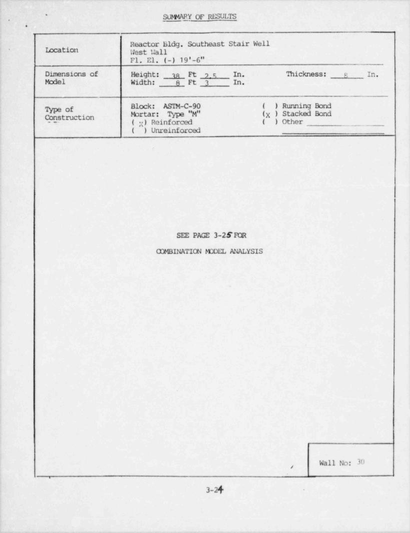
Reactor Bldg. Southeast Stair WellIocation West Hall-
Fl. El. (-) 19'-6"Dimensions of Height: u Ft ? _ c; In. 'Ihickness: R In.Model Width: 8 Ft 3 In.
Block: ASTM-C-90 ( ) Running BondType ofMortar: Type "M" (X ) Stacked BondConstruction( x) Reinforced ( ) Other- --
( ) Unreinforced
SEE PAGE 3-2SEOR
COMBINATION FODEL ANALYSIS
.
4
Wall No: 30,
.
3-2f -
_. -

SUlHARY OF RESULTS - (Cont'd.)*
3
'
( ) One Way. Frequency ( ) Vertical Span ToRange - Hz ( ) Horizontal Span(CrackedSection)
( X) Two Way _ 6.79 To 8.32(N-S) dir( X) 4-Edge Support *( ) 3-Edge Support 17.37 To 21.27(E-W)dir( ) Top, ( ) Side, Missing
- -- *w/ additional 2 L shape beams & bracings_
Response ( ) One Way: g, ( X) Two Way: 0.31g(N-S)dirAcceleration (OBE) OLE 0.15g (B-U)dir(CrackedSection) g, SSE 0.51g(N-S)dir
(SSE) 0.30g(E-W)dir
( ) ma ( ) parallel, to Bed JointS ses(Cracked f(Steel): vsSection)
(OBE+DL) (Allowable)vs
(SSE+DL) (Allowable)
(Conc.): vs(OE+DM (All M le)(Ccmpression),
vs(SSE+DL) (Allowable)
(X ) Two Way:(X ) Normal to Bed Joint
3816 vs 20,000f(Steel) :(OBE+DL) (Allowable)6303 vs 36,000
(SSE+DL) (Allowable),
f(Conc.) -100 vs -396:(OBE+DL) (Allowable)
-166 vs -1020(SSE+DL) (Allowable)
( X) Parallel to Bed Jointf(Steel): 10,467 vs 30,000
| (OBE+DL) (Allowable)! 17,326 vs 63,000|i (SSE+DL) (Allowable)
Remarks Combination Model Good for CrackedSection with two L Shape Beams & Bracings Wall No. 29&30Provided
[ 3-25

'
SUPNARY OF RESULTS.
e .
Reactor Bldg. Shutdown Heat Exchanger Rocxa.Location North Wall, Inthrm. Section*
Fl. El. 51 '-3"
Dimensions of Height: o Ft 11 In. Thickness: 24 In.
Model Width: 14 Ft 11 In.
Block: AS7M-C-90 ( ) Running BondType ofMortar: Type "M" ( X , Stacked Bond
Consf.ruction( ) Reinforced ( X) Other grouted double-
(X ) Unreinforced Wythe 12 in. each wythe.
(X ) One Way(X ) Vertical Span 25.03 To 30.65( ) Horizontal SpanFrequency
Range - Hz(Uncracked ( ) Two WaySection) ( ) 4-Edge Support 7b
( ) 3- Edge Support( ) Top, ( ) Side, Missing
ResponseAcceleration ( X ) One Way 0.32 g, ( ) Two Way: g,(Uncracked (OBE) (OBE)
Section) 0.52 g, g,(SSE) (SSE)
( X ) One Way:
Flexural Tensile ( X ) Normal to Bed Joint, 25.4 vs 40.0Stresses - psi (OBE+DL) (Allowable)(Uncrakced 43.1 vs 67.0Section) (SSE+DL) (Allowable)
( ) Parallel to Bed Joint, vs(OBE+DL) (Allowable)
vs(SSE+DL) (Alltvable)
( ) 'No Way:( ) Normal to Bed Joint, vs o,
(OBE+DL) (Allowable)vs
(SSE+DL) (Allowable)( ) Parallel to Bed Joint, vs
(OBE+DL) (Allowable)vs
(SSE+DL) (Allowable)
O.K. for One Way Model with top support.Remarks Provide additional support for equipnent. Wall No: 43
3-26
.. - -. .- - - - . . -. .
, _ .
..
. .,:
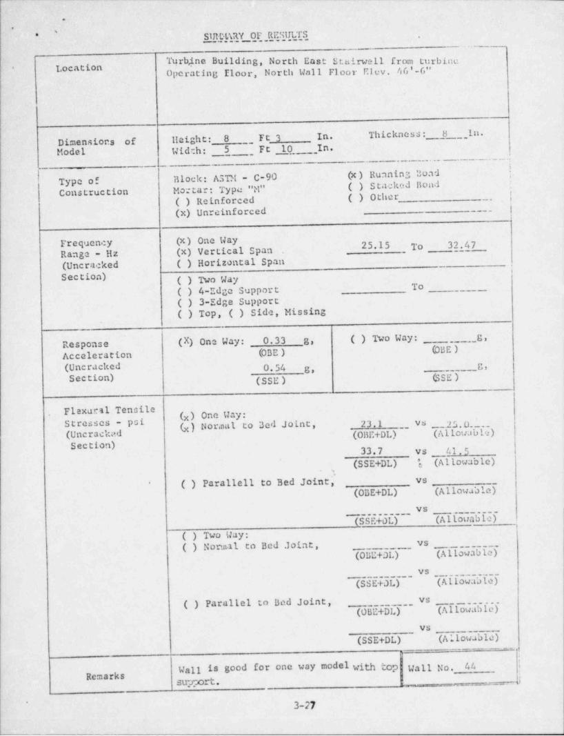
SIRDL\RY OF RESULTS'* ,
Turb,ine Building, North East Stairwell from turbineLocation* Operating Eloor, North Wall Floor Elev. 46'-6"
Dimensions of lleight: 8 , FC 3 In. Thickness: 8 _In.;
Model Wide.h: __ 5 _ _ Ft 10 In._
_-
1:~
Type of Block: ASTM - C-90 (x) Running Boad '.|'
Construction Mo: tar: Type "M" ( ) Stacked nond( ) Reinforced ( ) Other _,
,
j
(x) Unreinforced. ___,
|lFrequency (x) One Way 25.15 To 32.47Range - Hz (x) Vertical Span(Uncracked ( ) Horizontal SpanSection) ( ) No Way
To( ) 4-Edge Support( ) 3-Edge Support( ) Top, ( ) Side, Missing
Response (X) One Way: 0.33 g, ( ) Two Way: _ OBE)_
g,
Acceleration (OBE )
(Uncracked 0.54 g* g,
Section) (.33g ) GSE)
Flexural Tensile. (x) One Way:
-.25. Ol_S s - p a r. (x) Nor.nal to Bed Joint, _ 23.1 vs
( (OBE+DLT (Allowable)'
Section) 33.7 vs 41.5
(Allowable)*(SSE+DL) e
( ) Parallell to Bed Joint' vs'
, ~ (OBE+DL) (Allowable)vs
(SSE+0L) (Allouabic)( ) Two Way:
vs( ) Normal to Bed Joint,__(OBE+DL) (Allowable)
___
_ _ _ _ _ _ _
vs
(SSE+0L) (Allowable)vs( ) Parallel to Bod Joint,
(OBE+DL) (Allowable)vs
(SSE+DL) (Allowable)
Wall is good for one way model with top Wall No. 44Remarks ,jmrppod.
_
_ _ , __,
3-27.

I'
.
L
*
, . ,
CAIf0 LATED SHEAR STRESSES AND ALIONABLES FOR RUNNING BOND WALLS
Out of Plane In Plane ShearFlexural (PSI) ;
Shear (PSI) ;!
Wall No.' OBE SSE OBE SSE REMARKS |__
1 5 6.6 9.9.
6 6.6 9.9 Results are calcula-lated for the critic-al vall N^. 6.
7 6.6 9.9 2.7 5.3
17 9.3 12.8
18 7.0 11.3 |Deleted fran Anal.
21
22 7.7 12.1
23 11.1 15.3
24-1 3.6 7.9 pesults are calculatedfor the critical wall4o. 24-1.
24-2 3.6 7.9+ma
25 8.9 13.3
26 11.2 17.0_
27 7.8 11.9
28 11.1 17.1.
44 6.3 10.3. . - - . .
Allow. 38.1 31.2 OBE
Stresses(PSI) 49.5 40.6 1.3 (OBE)
-
Note: In plane shear stress is not critical wherever it is not given.
"
3-28
_.. __ , __. _ _ _ _ _ _ , . _ _ . . _ ._- _

f --
f,,^
:=, CALQLATED SHEAR STRESSES AND ALIDWABLES FOR STAQTD BOND WALLS
Out-of-Pl ane In-Plane ShearFlexural Shear (PSI)(Shear (PSI)
Wall No. OBE SSE OBE SSE REMARKS
1
8 8.2 13.3_ _ . _
- - - 15 4.0 7.3
19 5.3 9.3
20 5.2 9.1_ _ _
29830 10.0 16.0 17.0 27.0 CombinationModel with3-D Seismic Force
31 To be analyzed later
32 To be analyzed later
33 To be analyzed later_ _
43 3.1 4.9
45 To be analyzed later_
Allow. 25.4 20.8 . .- O_BE , - - - - -._
(PSI) 33.0 27.1 1.3 (0BE)_
Note: In plane shear stress is not critical wherever it is not given.
.
3-29
-!l

_-- __ _ -_ __ __
1-- _. 1_
"OYSTER CREEK NL' CLEAR STAT 105
IN PLANE STRAIN DUE 'IO OBE 3,
!
.
Bldg. Fir. Mass Fir. Max. Story Diff. In-PlaneModel No. Elev. Disp. Height Disp. Strain Remarks Results
-55 75.25 2.795 x 10- 24.00 0.868 x 10' 3.62 x 10 Allowable ,All
Reactor 6 51.25 1.927 27.75 0.994 3.58 Strain Walls-4 Satisfy
Bldg. 7 23.50 0.933 23.50 0.473 2.01 _y(68x10 In-Plane8 0.00 0.460 19.00 0.460 2.42 Strain
-- -- '9Base -19.00 0.000
Turbine 1 46.50 0.599 23.00 0.282 1.23
Bldg. 2 23.50 0.317 23.50 0.317 1.35
Base 0.00 0.'000 -- --
,
NOTES: 1. All masonry walls investigated are within the scope ofthe tabulated elev. and classified as confined walls.,
2. All linear units in ft.e
_
_ - .
,
'3-30,

_. ._____ - _-_ - _ _ _ _ . _ _ _ _ _ _ _ _ _ _ _
. -
OYSTER CREEK KUCLEAR STATION *IN PIANE STRAIN DUB TO SSE
, -
| 1
!BLDG FLR MASS FLR MAX Story Diff. IN PLANE REMARKS RESULT 6Model No. ELEV. DISP. Height DISP. STRAIN
Reactor 5 75.25 5.591X10 24.00 1.738X10 7.24X10 Allowable AllBLDC 6 51.25 3.853 27.75 1.986 7.16 Strain
3Walls
! 7 23.50 1.867 23.50 0.947 4.03 fc(1.33X10 satisfy8 0.00 0.920 19.00 0.920 4.84 In-Plana.
Base -19,00 0.000 strain# require-_
ment
Turbine; Bldg 2 46.50 1.197 23.00 0.564 2.45
1 23.50 0.633 23.50 0.633 2.69Base 0.00 0.000 -
.
t
j For Notes see the Preceeding page.,
!.i
|
i
,
3-31
.
1