Embed Size (px)
Citation preview

OPERATOR’S M A N U A L
R E G I S T E R WA R R A N T Y O N L I N E AT W W W. H E N N Y P E N N Y. C O M
PRESSURE FRYER (Gas)
MODELPFG-690PFG-692


Aug. 2003
DO NOT STORE OR USE GASOLINE OR OTHER FLAMMABLE VAPORS AND LIQUIDS IN THE VICINITY OF THIS OR ANY OTHER APPLIANCE. FIRE OR EXPLOSION COULD RESULT.
This manual should be retained in a convenient location for future reference.
A wiring diagram for this appliance is located on the rear shroud cover of the control panel.
Post in a prominent location, instructions to be followed if user smells gas. This information should be obtained by consulting the local gas supplier.
Do not obstruct the flow of combustion and ventilation air. Adequate clearance must be left all around appliance for sufficient air to the combustion chamber.
The Model PFG-690 pressure fryer is equipped with a continuous pilot. But fryer cannot be operated with out electric power. Fryer will automatically return to normal operation when power is restored.
Keep appliance area free and clear from combustibles.
Improper installation, adjustment, alteration, service or maintenance can cause property damage, injury or death. Read the installation, operating and maintenance instructions thoroughly before installing or servicing this equipment.

Technical Data for CE Marked ProductsNominal Heat Input: Natural (I2H) = 26,4 kW (90,000 Btu/h) (Net) Natural (I2E) = 26,4 kW (90,000 Btu/h) Natural (I2S) = 23,75 kW (81,000 Btu/h) Liquid Propane (I3P) = 27,0 kW (92,000 Btu/h)
Nominal Heat Input: Natural (I2H) = 29,3 kW (100,000 Btu/h) (Gross) Natural (I2E) = 29,3 kW (100,000 Btu/h) Natural (I2S) = 26,4 kW (90,000 Btu/h) Liquid Propane (I3P) = 29,3 kW (100,000 Btu/h)
Supply Pressure: Natural (I2H) = 20 mbar Natural (I2E) = 20 mbar Natural (I2S) = 25 mbar Liquid Propane (I3P) = 37/50 mbar
Test Point Pressure: Natural (I2H) = 8,7 mbar Natural (I2E) = 8,7 mbar Natural (I2S) = 8,7 mbar Liquid Propane (I3P) = 25 mbar
Injector Size: Natural (I2H) = 2,51 mm Natural (I2E) = 2.51 mm Natural (I2S) = 2.85 mm Liquid Propane (I3P) = 1,40 mm
This appliance must be installed in accordance with the manufacturer’s instructions and the regulations in force and only used in a suitable ventilated location. Read the instructions fully before installing or using the appliance.
Datos Tecnicos Para Products CEConsumo Calorico Nominal: Gas Natural (I2H) = 26,4 kW (90,000 Btu/h) (Neto) Gas Natural (I2E) = 26,4 kW (90,000 Btu/h) Gas Natural (I2S) = 23,75 kW (81,000 Btu/h) Propano Licuado (I3P) = 27,0 kW (92,000 Btu/h)
Consumo Calorico Nominal: Gas Natural (I2H) = 29,3 kW (100,000 Btu/h) (Bruto) Gas Natural (I2E) = 29,3 kW (100,000 Btu/h) Gas Natural (I2S) = 26,4 kW (90,000 Btu/h) Propano Licuado (I3P) = 29,3 kW (100,000 Btu/h)
Presion De Alimentacion: Gas Natural (I2H) = 20 mbar Gas Natural (I2E) = 20 mbar Gas Natural (I2S) = 25 mbar Propano Licuado (I3P) = 37/50 mbar
Presion En Ez Punto De Prueba: Gas Natural (I2H) = 8,7 mbar Gas Natural (I2E) = 8,7 mbar Gas Natural (I2S) = 8,7 mbar Propano Licuado (I3P) = 25 mbar
Diámetro Boquilla: Gas Natural (I2H) = 2,51 mm Gas Natural (I2E) = 2.51 mm Gas Natural (I2S) = 2.85 mm Propano Licuado (I3P) = 1,40 mm
Este equipo debe instalarse únicamente en un recinto adecuadameute ventilado y conforme a las indicaciones del fabri-cante y a las normas vigentes. Lea completamente las instrucciones antes de instalar o usar este equipo.

HENNY PENNY 8 HEAD GAS PRESSURE FRYER
SPECIFICATIONS
Height 61” (155 cm) Width 24” (61 cm) Depth 41¾” (106 cm) Floor Space Approximately 7 sq. ft. (0.65 sq. m.) Pot Capacity 8 head of chicken (24 lbs.) (10.9 kg) 130 lbs. shortening (59 kg) Electrical 120 VAC, 1 Phase, 50/60 Hz, 10 Amp, 3 Wire Service 230 VAC, 1 Phase, 50 Hz, 3 Wire Service Heating Propane or Natural Gas; 100,000 btu/hr (105 MJ/hr) Pressure 12 psi operating pressure (827 mbar) 14.5 psi safety relief pressure (999 mbar) Shipping Weight Approximately 935 lbs. (424 kg)
A data plate, located on the back shroud behind the lid, gives the information of the type of fryer, serial number, warranty date, and other information pertaining to fryer. Also, the serialnumber is stamped on the outside of the frypot. See figure below.

iJune 2012
TABLE OF CONTENTS
Section Page
Section 1. INTRODUCTION ..................................................................................................... 3 1-1. Pressure Fryer ................................................................................................ 3 1-2. Proper Care .................................................................................................... 3 1-3. Assistance ...................................................................................................... 3 1-4. Safety ............................................................................................................. 4 Section 2. INSTALLATION ....................................................................................................... 5 2-1. Introduction ................................................................................................... 5 2-2. Unpacking Instructions .................................................................................. 5 2-3. Selecting the Location ................................................................................... 9 2-4. Leveling the Fryer ......................................................................................... 9 2-5. Ventilation of Fryer........................................................................................ 10 2-6. Gas Supply..................................................................................................... 10 2-7. Gas Leak Test ................................................................................................ 13 2-8. Gas Pressure Regulator Setting ..................................................................... 13 2-9. Electrical Requirements ................................................................................. 15
Section 3. OPERATION INSTRUCTIONS ............................................................................... 17 3-1. Operating Components .................................................................................. 17 3-2. Lid Operation................................................................................................. 21 3-3. Melt Cycle Operation .................................................................................... 22 3-4. Controls and Indicators.................................................................................. 23 3-5. Display Messages .......................................................................................... 24 3-6. Filling or Adding Shortening ......................................................................... 25 3-7. Basic Operation ............................................................................................. 26 3-8. Care of the Shortening ................................................................................... 28 3-9. Filtering of Shortening .................................................................................. 29 3-10. Changing the Filter Envelope ........................................................................ 31 3-11. Lighting and Shutdown of the Burners ......................................................... 31 3-12. Cleaning the Frypot ....................................................................................... 32 3-13. Filter Pump Motor Protector-Manual Reset .................................................. 33 3-14. Regular Maintenance Schedule ..................................................................... 33 3-15. Preventive Maintenance ................................................................................ 34 3-16. Programming ................................................................................................. 40 3-17. Special Program Mode .................................................................................. 42 Section 4. TROUBLESHOOTING .............................................................................................. 47 4-1. Troubleshooting Guide ................................................................................... 47 4-2. Error Codes .................................................................................................... 48
Appendix A. ANNUAL PREVENTIVE MAINTENANCE ........................................................... 51

HENNY PENNY8 HEAD ELECTRIC PRESSURE FRYER
Fryer must be installed and used in such a way to prevent water from contacting the shortening.
This appliance is not intended to be operated by means of an external timer or a separate remote control system.
This appliance is not intended for use by persons (including children) with reduced physical, sensory or mental capabilities, or lack of experience and knowledge, unless they have been given supervision or instruction concerning use of the appliance by a person responsible for their safety.

3Feb. 2007
1-1. PRESSURE FRYER
1-2. PROPER CARE
1-3. ASSISTANCE
SECTION 1: INTRODUCTIONThe Henny Penny Pressure Fryer is a basic unit of food processing equipment which is used only in institutional and commercial food service operations.
P-H-T A combination of pressure, heat, and time is automatically controlled to produce the optimum in a tasty, appealing product. PRESSURE Pressure is basic to this method of food preparation. The pressure is developed from the natural moisture of the food. The patented lid traps this moisture and uses it as steam. Because the steam builds rapidly, a greater part of the natural juices are retained within the food. A deadweight assembly vents excess steam from the pot and maintains constant live steam pressure. HEATHeat generated is another important factor of the pressure fryer. Energy savings is realized due to the unit’s short frying time, low temperature, and heat retention of the stainless steel frypot. TIME Time is important because the shorter time involved in frying foods results in additional economies for the user. Foods are table ready in less time than it would take to fry them in a conventional open-type fryer.
As of August 16, 2005, the Waste Electrical and Electronic Equipment directive went into effect for the European Union. Our products have been evaluated to the WEEE directive. We have also reviewed our products to determine if they comply with the Restriction of Hazardous Substances directive (RoHS) and have redesigned our products as need-ed in order to comply. To continue compliance with these directives, this unit must not be disposed as unsorted municipal waste. For proper disposal, please contact your nearest Henny Penny distributor.
As in any unit of food service equipment, the Henny Penny Pressure Fryer does require care and maintenance. Requirements for the maintenance and cleaning are contained in this manual and must become a regular part of the operation of the unit at all times.
Should you require outside assistance, call your local independent distributor in your area, call Henny Penny Corp. at 1-800-417-8405 or 1-937-456-8405, or go to Henny Penny online at www.hennypenny.com.

4July 2003
1-4.SAFETY
The instructions in this manual have been prepared to aid you in learning the proper procedures for your equipment. Where information is of particular importance or is safety related, the words NOTICE, CAUTION, or WARNING are used. Their usage is described below.
If a problem occurs during the first operation of a new unit, recheck the Installation Section of the Operator’s Manual.
Before troubleshooting, always recheck the Operation Section of the Operator’s Manual.
SAFETY ALERT SYMBOL is used with DANGER, WARNING or CAUTION which indicates a personal injury type hazard.
NOTICE is used to highlight especially important information.
CAUTION used without the safety alert symbol indicates a potentially hazardous situation which, if not avoided, may result in property damage.
CAUTION used with the safety alert symbol indicates a potentially hazardous situation which, if not avoided, could result in minor or moderate injury.
WARNING indicates a potentially hazardous situation which, if not avoided, could result in death or serious injury.
DANGER INDICATES AN IMMINENTLY HAZARDOUS SITUATION WHICH, IF NOT AVOIDED, WILL RESULT IN DEATH OR SERIOUS INJURY.
Where information is of particular importance or is safety related, the words DANGER, WARNING, CAUTION, or NOTICE are used. Their usage is described as follows:

5July 2003
2-2. UNPACKING
INSTRUCTIONS
2-1. INTRODUCTION
SECTION 2: INSTALLATIONThis section provides the installation and unpacking instructions for the Henny Penny PFG-690.
Installation of this unit should be performed only by a qualified service technician.
Do not puncture the fryer with any objects such as drills or screws as electrical shock or component
damage could result.
Any shipping damage should be noted in the presence of the delivery agent and signed prior to his or her
departure.
1. Cut and remove the plastic bands from the main box.
2. Remove the box lid and lift the main box off the fryer.
3. Remove four corner packing supports.
4. Cut the stretch film from around the carrier/rack box and remove it from the top of the fryer lid.
5. Cut and remove the metal bands holding the fryer to the pallet.
6. Remove the fryer from the pallet.
All counterweights must be loaded before unlatching the lid, or personal injury could result.
Take care when moving the fryer to prevent personal injury. The fryer weighs approximately
935 lbs. (424 kg).

6Dec. 2016
CAP
DEADWEIGHT
SHIPPINGSUPPORT(DISCARD)
HOUSING
7. Remove the counterweights, which are strapped to the pallet under the fryer, from the pallet.
8. Remove rear service cover.
9. Load the 7 weights into the counterweight assembly.
10. Replace rear service cover.
11. Cut warning tags from the lid assembly. The lid may now be unlatched.
12. Remove the accessories from inside the filter drain pan.
13. Prepare the deadweight valve for operation The metal shipping support is placed within the deadweight assembly housing to protect the deadweight orifice and dead-weight during shipment. This support must be removed prior to installation and start-up.
a. Unscrew the deadweight cap.b. Remove the deadweight.c. Remove and discard the shipping support.d. Clean the deadweight orifice with a dry cloth.e. Carefully place deadweight over deadweight orifice. Replace
deadweight cap, finger tight.
14. Remove the protective paper from the fryer cabinet. Clean exterior surface with a damp cloth.
2-2. UNPACKING
INSTRUCTIONS(CONT.)
Do not drop. The counterweights weigh approximately 18 lbs. (8.1 kg) each. Handle with care,
or personal injury could result.
To avoid personal injury and assure safe operation of unit, rear service cover must be in place.
The fittings for installing the gas line are in a separate box, along with the accessories, in the filter drain pan.

7Dec. 2016
ROLL
UN
IT O
FFPA
LLET
ON
TORA
MP.
ORI
ENT
CAST
ERS
IN S
IDEW
AYS
POSI
TIO
N.R
AIS
E SI
DE
SLIG
HTL
Y &
KNO
CK O
UT
RUBB
ERPA
DS
(2).
-TY
PICA
L BO
TH S
IDES
PRY
OFF
RAIL
-EI
THER
SID
E PRO
P U
P A
RAM
P FO
R EA
CHCA
STER
ON
THE
SELE
CTED
SID
E.
REM
OVE
REA
RCO
VER
-WEI
GH
T SE
GM
ENTS
MU
ST B
E IN
STA
LLED
PER
INST
RUC
TIO
NCO
NTA
INED
THER
EIN
BEFO
REAT
TEM
PTIN
GTO
UN
LATC
H L
ID.
REM
OVE
THE
�AC
CESS
ORI
ES F
ROM
THE
DRA
INPA
N.
NOTE
:TH
E FI
TTIN
GS
FOR
GA
S LI
NE
ARE
HER
E!!
REM
OVE
THE
WEI
GH
TS F
ROM
THE
PALL
ET.
Optional Ramp Unloading

8Dec. 2016
A
A
REMOVE 2 BOLTS MARKED“A” TO RELEASE FRAMEAFTER INSTALLING WEIGHTSEGMENTS
INSERT 4TH
INSERT 2ND & 3RDSEGMENT
INSERT 1STSEGMENT
EACH WEIGHT SEGMENT WEIGHS APPROXIMATELY 18 LBS. (8.1 KG) -HANDLE WITH CARE
ALL SEGMENTS ARE IDENTICAL.
ALL SEGMENTS MUST BE INSTALLED AND SECURED IN THE FRAMBEFORE ATTEMPTING TO UNLATCH LID.

9April 2008
2-3. SELECTING THE
LOCATION
2-4. LEVELING THE
FRYER
The proper location of the fryer is very important for operation, speed, and convenience. Choose a location which will provide easy loading and unloading without interfering with the final assembly of food orders. Operators have found that frying from raw to finish, and holding the product in a warmer provides fast, continuous service. Landing or dumping tables should be provided next to, at least, one side of the fryer. Keep in mind the best efficiency will be obtained by a straight line operation, i.e., raw in one side and finish out the other side. Order assembly can be moved away with only a slight loss of efficiency. To properly service the fryer, 24 inches (60.96 cm) of clearance is needed on all sides of the fryer. Access for servicing can be attained by removing a side panel. Also, at least 6 inches (15.24 cm) around the base of the unit is needed for proper air supply to the combustion chamber.
To avoid a fire, install the fryer with minimum clearance from all combustible and noncombustible
materials, 6 inches (15.24 cm) from side and 6 inches (15.24 cm) from back. If installed properly, the gas fryer is designed for operation on combustible floors
and adjacent to combustible walls.
To avoid fire and ruined supplies, the area under the 690 fryer should not be used to store supplies.
Do not spray aerosols in the vicinity of this appliance while it is in operation.
To prevent severe burns from splashing hot shortening, position and install fryer to prevent
tipping or movement. Restraining ties may be used for stabilization.
FAILURE TO FOLLOW THESE LEVELING INSTRUCTIONS CAN RESULT IN
SHORTENING OVERFLOWING THE FRYPOT WHICH COULD CAUSE SERIOUS BURNS,
PERSONAL INJURY, FIRE, AND/OR PROPERTY DAMAGE.
For proper operation, level the fryer from side to side and front to back, using level on the flat areas around the frypot collar.
10July 2003
2-5. VENTILATION OF
FRYER
2-6. GAS SUPPLY
Ventilation must conform to local, state, and national codes. Consult your local fire department or building
authorities.
Do not attempt to use any gas other than that specified on the data plate. Incorrect gas supply could cause a fire or explosion resulting in severe
injuries and/or property damage.
To avoid possible serious personal injury:
• Installation must conform with local, state, and national codes, and be in accordance with Canadian Gas Authority Standard CSA B149-& 2, Installation Codes - Gas Burning Appliances and in accordance with Australian Gas Association current edition of AS5601 Gas Installations.
• The fryer and its manual shutoff valve must be disconnected from the gas supply piping system during any pressure testing of that system at test pressures in excess of 1/2 psig (3.45kPa)(34.47mbar) (continued to next page)
The fryer must be located with provision for venting into adequate exhaust hood or ventilation system. This is essential to permit efficient removal of the flue gases and frying odors. Special precaution must be taken in designing an exhaust canopy to avoid interference with the operation of the fryer. We recommend you consult a local ventilation or heating company to help in designing an adequate system.
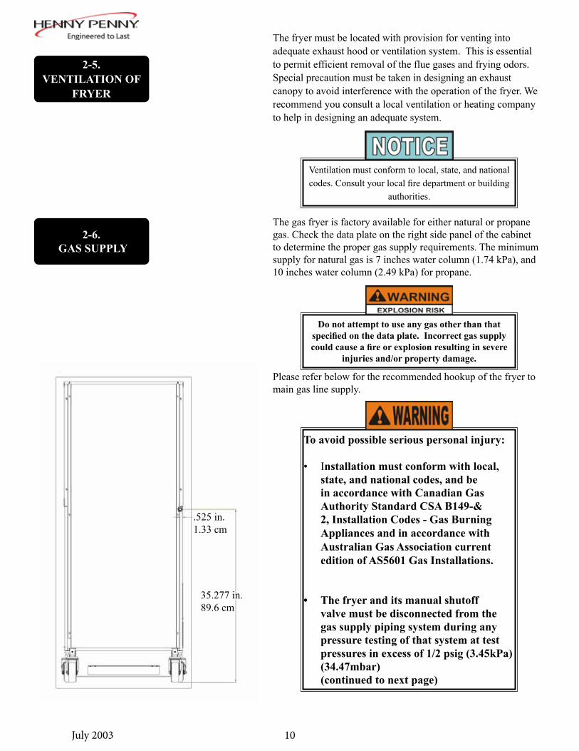
Please refer below for the recommended hookup of the fryer to main gas line supply.
.525 in.1.33 cm
35.277 in.89.6 cm
The gas fryer is factory available for either natural or propane gas. Check the data plate on the right side panel of the cabinet to determine the proper gas supply requirements. The minimum supply for natural gas is 7 inches water column (1.74 kPa), and 10 inches water column (2.49 kPa) for propane.

11July 2003
2-6. GAS SUPPLY
(CONT.) • The fryer must be isolated from the gas supply piping system by closing its manual shutoff valve during any pressure testing of the gas supply piping system at test pressures equal to or less than 1/2 psig (3.45 kPa)(34.47 mbar).
• A standard 3/4 inch, black steel pipe and malleable fittings should be used for gas service connections.
• Do not use cast iron fittings.
• Although 3/4 inch size pipe recommended, piping should be of adequate size and installed to provide a supply of gas sufficient to meet the maximum demand without undue loss of pressure between the meter and the fryer. The pressure loss in the piping system should not exceed 0.3 inch water column (0.747 mbar).
Provisions should be made for moving the fryer for cleaning and servicing. This may be accomplished by:
1. Installing a manual gas shutoff valve and disconnect union, or
2. Installing a heavy-duty (min. 3/4 inch) design A.G.A. certified connector which complies with standard connectors for moveable gas appliances. ANSI Z21.69 or CAN/CSA 6.16. Also, a quick-disconnect coupling which complies with the Standard for Quick-Disconnect Devices for use with Gas Fuel, ANSI Z21.41 or CAN 1-6.9. Also, adequate means must be provided to limit the movement of the fryer without depending on the connector and any quick-disconnect device or its associated piping to limit the fryer movement.
3. See the illustration on the following page for the proper connections of the flexible gas line and cable restraint.
The cable restraint limits the distance the fryer can be pulled from the wall. For cleaning and servicing the fryer, the cable must be unsnapped from the unit and the flexible gas line disconnected. This will allow better access to all sides of the fryer. The gas line and cable restraint must be reconnected once the cleaning or servicing is complete.

12Dec. 2016
Couplings and hose shouldbe installed in the sameplane as shown at left. DONOT OFFSETCOUPLINGS -- this causestorsional twisting andundue strain causingpremature failure
This is the correct way toinstall metal hose vorvertical traverse. Note thesingle, natural loop.Allowing a sharp bend, asshown at right, strains andtwists the metal hose to apoint of early failure at thecoupling
Maintain the minimum orlarger bending diameterbetween the couplings forlongest life.Closing in the diameter atthe coupling, as shown atright, creates double bendscausing work work fatiguefailure of the fittings.
In all installations where“self-draining” is notnecessary, connect metalhose in a vertical loop.DO NOT CONNECTMETAL HOSE �HORIZONTALLY...unless“self-draining” is necessary,then use support on lowerplane as shown at left.
CABLE RESTRAINTPlease refer to the illustration belowwhen installing cable restraint on allmoveable gas fryers.
I-bolt is to be secured to the buildingusing acceptable building contructionpractices.
DRY WALL CONSTRUCTIONSecure I-bolt to a building stud DONOT attach to dry wall only. Also,locate the I-bolt at teh same height asthe gas service. Preferred installationis approximately six inches to eitherside of service. Cable restraint mustbe at least six inches shorter thanflexible gas line.
Utilize elbows when necesary to avoidsharp kinks or excessive bending. Forease of movement, install with a“lazy” loop. gas appliance must bedisconnected prior to maximummovement. (Minimum movement ispermissible for hose disconnection).
MINIMUM PULL of equipmentaway from wall permissiblefor accessibility to QuickDisconnect Device
AVOID SHARP BENDS AND KINKS whenpulling equipment away from wall. (Maximumpull will kink ends, even if installed properly,and reduce Connector life.)
GAS PIPING
DISCONNECTBEFOREMAXIMUM PULL
MINIMUM PULL FORACCESSIBILITYONLY
MAXIMUM PULL NOTADVISED WHILECONNECTED
QUICK DISCONNECTDEVICE still attachedwhile extended atmaximum pull
STRESSPOINTS
STRESSPOINTS
12160004
2-6. GAS SUPPLY
(CONT.)

13July 2003
2-7. GAS LEAK TEST Prior to turning the gas supply on, be sure the gas valve
knob on the gas control valve is in the OFF position. The word OFF is at the bottom of the knob when the
valve is closed.
The gas pressure regulator has been set by Henny Penny and is not to be adjusted by the user.
MAKE SURE GAS PRESSURE IS SET CORRECTLY. FAILURE TO DO SO CAN
RESULT IN SHORTENING OVERFLOWING THE FRYPOT, WHICH COULD CAUSE
SERIOUS BURNS, PERSONAL INJURY, FIRE, AND/OR PROPERTY DAMAGE.
To avoid fire or explosion, never use a lighted match or open flame to test for gas leaks. Ignited gas could
result in severe personal injury and/or property damage.
Upon initial installation, and after moving the unit, the piping and fittings should be checked for gas leaks. A simple checking method is to turn on the gas, and brush all connections with a soap solution. If bubbles occur, it indicates escaping gas. In this event, the piping connection must be redone.
2-8. GAS PRESSURE
REGULATOR SETTING
The gas pressure regulator on the gas control valve is factory set as follows: Natural: 3.5 inches water column (0.87 kPa) Propane: 10.0 inches water column (2.49 kPa)

14Oct. 2013
2-8. GAS PRESSURE
REGULATOR SETTING(CONT.)
Figure 1
Figure 2
Figure 3
MEASURING GAS PRESSURE
1. Locate the pressure tap hole or fitting on the side of the gas valve. Remove the pipe plug from the valve or fitting circled in Figure 1.
2. Screw a pressure tap fitting into the valve or the fitting on the side of the valve circled in Figure 2.
3. Place one end of a vacuum hose on the pressure tap fitting and the other end on the manometer as shown in Figure 3.
4. Turn the fryer “ON”.
5. Allow the fryer to reach full burn.
6. The pressure reading on the manometer should be 3.5” of water column for Natural gas and 10” of water column for LP gas.
7. Turn the fryer off.
8. Remove the pressure tap fitting.
9. Place the pipe plug back into the valve or the fitting on the valve.
Notify a qualified service technician if gas pressure differs from factory settings mentioned in this manual

15July 2003
2-9. ELECTRICAL
REQUIREMENTS
To avoid electrical shock, do not disconnect the ground (earth) plug. This fryer must be adequately
and safely grounded (earthed). Refer to local electrical codes for correct grounding (earthing) procedures or in absence of local codes, with The
National Electrical Code, ANSI/ NFPA No. 70-(the current edition). In Canada, all electrical
connections are to be made in accordance with CSA C22.1, Canadian Electrical Code Part 1, and/or
local codes.
To avoid electrical shock, this appliance must be equipped with an external circuit breaker which will disconnect all ungrounded (unearthed) conductors. The main power switch on this appliance does not
disconnect all line conductors.
The gas fryer requires 120 volt, 60 Hertz, 1 phase, 10 amp, 3-wire grounded (earthed) service, or 230 volt, 50 Hertz, 1 phase, 5 amp, service. The 120 volt gas fryer is factory equipped with a grounded (earthed) cord and plug for your protection against shock, and should be plugged into a three-prong grounded (earthed) receptacle. Do not cut or remove grounding (earthing) prong. A wiring diagram is located behind the right side panel, and can be accessed by removing the side panel. The 230 volt plug must conform to all local, state, and national codes.

16July 2003
BOIL-OVER PREVENTION IN HENNY PENNY FRYERS
FAILURE TO FOLLOW THESE INSTRUCTIONS CAN RESULT IN SHORTENING OVERFLOWING THE FRYPOT WHICH COULD CAUSE SERIOUS BURNS,PERSONAL INJURY, FIRE,
AND/OR PROPERTY DAMAGE.
• THE SHORTENING SHOULD BE STIRRED ONLY DURING THE MORNING START-UP PROCEDURE. DO NOT STIR THE SHORTENING AT ANY OTHER TIME.
• FILTER THE SHORTENING AT LEAST TWICE A DAY.
• FILTER ONLY WHEN “COOL” IS DISPLAYED.
• BRUSH ALL CRACKLINGS FROM FRYPOT SURFACES AND THE COLD ZONE DURING THE FILTERING PROCESS.
• MAKE SURE THE FRYER IS LEVEL.
• BE CERTAIN THE SHORTENING IS NEVER ABOVE THE UPPER FRYPOT LEVEL INDICATOR LINES.
• BE CERTAIN THAT THE GAS CONTROL VALVE AND BURNERS ARE PROPERLY ADJUSTED (GAS UNITS ONLY).
• USE RECOMMENDED PRODUCT LOAD SIZE.
FOR ADDITIONAL INFORMATION ON THESE INSTRUCTIONS, REFER TO THE HENNY PENNY OPERATOR’S MANUAL AND THE KFC STANDARDS LIBRARY.
FOR ASSISTANCE, CALL THE HENNY PENNY SERVICE DEPARTMENT AT
1-800-417-8405 OR 1-937-456-8405.
17Oct. 2016
SECTION 3: OPERATION
3-1. OPERATING COMPONENT
POWER/PUMP SWITCH A three-way switch with center OFF position; move the switch to the position marked POWER to operate the fryer; move the switch to the position marked PUMP to operate the filter pump; certain conditions must be met prior to operation of the filter pump; these conditions are covered later in this section FRYPOTThis reservoir holds the cooking shortening, and is designed to accommodate the burner tubes, 8 head of product, and an ade-quate cold zone for collection of cracklings CARRIERThis stainless steel carrier consists of five racks, containing the food product during and after frying (4 cook racks and 1 cover rack)
LID GASKETProvides the pressure seal for the frypot chamber DEADWEIGHT ASSEMBLYThe deadweight style operating pressure relief valve is used to maintain a constant level of steam pressure within the frypot; any excess steam pressure is vented through the exhaust stack; remove the deadweight cap, and clean the cap, deadweight, and deadweight orifice once a day; see Preventive Maintenance Section
Failure to clean the deadweight assembly daily could result in the fryer building too much pressure.
Severe injuries and burns could result.

18Oct. 2016
SAFETY RELIEF VALVE
An ASME approved spring loaded valve set at 14.5 psi (999 mbar); in the event the operation valve becomes obstructed, this safety valve will release excess pressure, keeping the frypot chamber at 14.5 psi (999 mbar); if this occurs, turn the COOK/PUMP switch to the OFF position to release all pressure from the frypot
SAFETY RELIEF VALVE RING
PRESSURE GAUGEIndicates the pressure inside the frypot
3-1. OPERATING COMPONENT
(CONT.)
If safety relief valve activates, turn main power switch to the OFF position. To avoid serious burns and injuries, have fryer serviced before next use.
DURING OPERATION, THIS VALVE MAY DISCHARGE LARGE AMOUNTS OF HIGH PRESSURE STEAM, WATER, AIR, GAS, OR OIL. DO NOT CAP, PLUG OR OBSTRUCT
THE DISCHARGE. OBSTRUCTING THE DIS-CHARGE MAY RESULT IN SEVERE BURNS
AND/OR DAMAGE TO EQUIPMENT
DO NOT PULL THIS RING. SEVERE BURNS FROM THE STEAM WILL RESULT
DO NOT USE THE TEST LEVER OR RING AS A LIFTING DEVICE FOR INSTALLATION

19Oct. 2016
SOLENOID VALVEAn electromechanical device that causes pressure to be held in the frypot The solenoid valve closes at the beginning of the Cook Cycle and opens automatically at the end of the Cook Cycle; if this valve becomes dirty or the teflon seat nicked, pressure will not build and it must be repaired per the Maintenance Section of the Technical Manual
DRAIN VALVEA two-way ball valve, normally in the closed position; turn the handle to drain the shortening from the frypot into the filter drain pan
DRAIN INTERLOCK SWITCHA microswitch that provides protection for the frypot in the event an operator inadvertently drains the shortening from the frypot while the main switch is in the COOK position; the switch is designed to automatically shut off the heat when the drain valve is opened CONDENSATION DRAIN PANThe collection point for the condensation formed within the steam exhaust system; it must be removed and emptied periodically, usually daily
SHORTENING MIXING SYSTEMThe unit is equipped with a shortening mixing capability to ensure the shortening is properly mixed to prevent an accumulation of moisture, causing boiling action in the frypot; the filter pump is activated by the controls, at preset intervals, to mix the shortening LID LATCHThe fryer lid is equipped with a mechanical catch on the front of the lid which engages a bracket on the front of the frypot; this device holds the lid down while the lid is being locked into place,but is not meant to hold pressure in the frypot
HIGH TEMPERATURE LIMIT This is a safety component that senses the temperature of the shortening; if the temperature of the shortening exceeds 420°F (216°C), this control opens and shuts off the heat to the frypot; when the temperature of the shortening drops to a safe operation limit, the control must be manually reset by pressing the red reset button, located under the control panel, in the right, front of the fryer
3-1. OPERATING COMPONENT
(CONT.)
DO NOT OPEN THE DRAIN VALVE WHILE FRYPOT IS UNDER PRESSURE. HOT
SHORTENING WILL EXHAUST, AND SEVERE BURNS WILL RESULT.
High limit reset

20Oct. 2016
3-1. OPERATING COMPONENT
(CONT.)IGNITION MODULESThe two ignition modules send 24 volts to the gas control valve and high voltage to the ignitors SPARK IGNITORSWhen the pilots are being lit, the spark ignitors are electrically energized and the tip of the ignitors spark to ignite the pilot lights FLAME SENSORSSense the pilot lights when the power switch is turned on; if the pilots go out, or do not light, the flame sensors shut the gas off, via the modules GAS CONTROL VALVEA dual controller in which one side of the valve controls the pilot light and the other side controls the main burner
AIRFLOW SWITCHSenses the flow of air coming from the blower; if the airflow is reduced below a set amount, the switch cuts power to the gas control valve, which shuts down the burners
BLOWERAdds the proper amount of air into the burner tubes, so an effi-cient combustion takes place, and also, pulls the flue gases out to the flue
AIR VALVEPumps air into the shortening, periodically, to keep the shorten-ing at a uniform temperature; this only functions when the unit has been sitting idle for a period of time, and when heating up from a cold start
To avoid property damage, do not tamper with or disassemble this component. It is set and sealed from
the factory and is not to be adjusted.

21June 2012
TO OPEN LID:1. Gently raise handle until it stops.2. Push handle back until it stops.3. Lower handle.
4. Push handle back.5. Unlatch the front lid latch.
3-2. LID OPERATION
TO CLOSE LID:1. Lower the lid until gasket comes into contact with the pot and
lock the lid in place with the lid latch.
2. Pull lid handle forward until it stops.
3. Lift up on the lid handle until it stops.
4. Bring lid handle out towards you until it stops.
5. Push lid handle down, locking lid in place.
LID MUST BE LATCHED PROPERLY, OR PRESSURIZED SHORTENING AND STEAM
MAY ESCAPE FRYPOT. SEVERE BURNS WILL RESULT.
DO NOT LIFT HANDLE OR FORCE LID LATCH OPEN BEFORE PRESSURE GAUGE READS “0”
PSI. ESCAPING STEAM AND SHORTENING WILL RESULT IN SEVERE BURNS.
TO AVOID SERIOUS PERSONAL INJURY, DO NOT OPERATE WITHOUT LID COVER IN PLACE AND ALL COMPONENTS INSTALLED.
TO AVOID SERIOUS PERSONAL INJURY, DO NOT TAMPER WITH ANY COMPONENT OF
LID LOCKING MECHANISM.
If lid becomes difficult to operate, stop using the fryer
and call for service. Cables need replaced.
Lower the handle before attempting to raise the lid, or damage to the lid could result.
22July 2003
3-3. MELT CYCLE OPERATION
If the shortening is below 185°F (85°C) with the POWER/PUMP switch in the POWER position, the fryer will enter the Melt Cycle. The shortening is heated slowly to prevent scorching of the shortening. The heat will cycle on and off to ensure slow melting of shortening. At 185o F (85o C), the heat stays on until 250o F (121o C), the Cool Mode is reached. To exit the Cool Mode, press the EXIT COOL button. See Filling or Adding Shortening Section.
Refer to the images on the following pages. The 690 has three possible different decals for the controls - SMS, Non-SMS, and CE.

23
Model 590/592
Item Name Description1 SCAN Button Allows the operator to toggle through any running multiple
timers.2 Temperature Button Allows the operator to read the temperature of the shortening
while in a Cook Cycle.3 Digital Display Display shows cooking times along with any prompts or
messages.4 HEAT Indicator Illuminates whenever the control calls for heat; when short-
ening temperature is reached, the heat light goes off.5 EXIT FILL Button After filtering the fryer, if in the Filter Lockout Mode, the
display reads “FILL” and the EXIT FILL button must be pressed.
6 Menu Strip Shows the name of the product associated with each product button.
7 EXIT COOL Button After cooking or filtering the fryer automatically goes into cool mode (this keeps shorteneing at a lower temperature to preserve shortenening life). The EXIT COOL button must be pressed to heat the shortening to setpoint temperature.
8 Product Select Buttons Select the product to be cooked.9 FUNTION Button Used in the programming of the controls
Oct 2016
3-4. CONTROLS AND
INDICATORS
10160009
1
2 3 4
5
6
789

24July 2003
Model 590/592
There are messages shown on the digital display during operation. Some of the most common messages are described in the table below:
Message DescriptionHI The display reads “HI” if the shortening temperature is
40° F above the setpointDROP The display reads “DROP” when the shortening has
reached the setpoint temperature (will read “DROP” 2° before setpoint and 4° above setpoint).
DONE The display reads “DONE” at the end of the Cook Cycle.
3-5. DISPLAY MESSAGES

25July 2003
1. It is recommended that a high quality shortening be used in the fryer. Some low grade shortenings have a high moisture content and will cause foaming and boiling over.
2. The gas model requires 130 lbs. (59 kg) of shortening. The frypot has 4 level indicator lines inscribed on the rear wall of the frypot which show when the heated shortening is at the proper level. See photo at left.
3. Cold shortening should be filled to the lower indicators.
For complete instructions, refer to KFC’s Standards Library.
3-6.FILLING
OR ADDING SHORTENING
The shortening level must always be above the burner tubes when the fryer is heating and at the frypot level indicators on the rear of the frypot (See photo below).
Failure to follow these instructions could result in a fire and/or damage to the fryer.
When using solid shortening, it is recommended to melt
the shortening on an outside heating source before placing it in the frypots. The burner tubes must be
completely submerged in shortening. Fire or damage to the frypot could result.
BE CERTAIN THE SHORTENING IS NEVER ABOVE THE UPPER LEVEL
INDICATOR LINES. FAILURE TO FOLLOW THESE INSTRUCTIONS CAN RESULT IN
SHORTENING OVERFLOWING THE FRYPOT CAUSING SERIOUS BURNS, PERSONAL
INJURY, FIRE AND/OR PROPERTY DAMAGE.
To avoid severe burns when pouring hot shortening into frypot, wear gloves and take care to avoid
splashing.

26July 2003
Follow the procedure below on the initial start-up of the fryer and each time the fryer is brought back into operation from a cold, or shutdown condition, . These are basic, general instructions. Be sure to follow KFC’s Standards Library when operating the fryer.
1. Make sure the shortening is filled to the two lower level indicators in the frypot.
2. Turn the POWER/PUMP switch to the POWER position and press the appropriate product button to select the amount of product to be cooked.
3. Stir the shortening as it is heating up from a cold start. Be sure to stir down into the cold zone.
DO NOT OVERLOAD, OR PLACE PRODUCT WITH EXTREME MOISTURE CONTENT INTO THE RACKS. 32 LBS. (14.5 KG) IS
THE MAXIMUM AMOUNT OF PRODUCT PER FRYPOT. FAILURE TO FOLLOW
THESE INSTRUCTIONS CAN RESULT IN SHORTENING OVERFLOWING THE FRYPOT
WHICH COULD CAUSE SERIOUS BURNS, PERSONAL INJURY, FIRE AND/OR PROPERTY
DAMAGE.
DO NOT STIR THE SHORTENING AT ANY OTHER TIME EXCEPT AT MORNING START-UP. FAILURE TO FOLLOW THESE INSTRUC-TIONS CAN RESULT IN SHORTENING OVER-
FLOWING THE FRYPOT WHICH COULD CAUSE SERIOUS BURNS, PERSONAL INJURY,
FIRE, AND/OR PROPERTY DAMAGE.
The controls have a 45-second delay from when the power switch is turned on to when the burners ignite.
All safety devices shut off the gas supply to the burner. Follow the above procedures to restart the fryer.
Notify a qualified service technician if the shutdown is repeated.
3-7.BASIC
OPERATION

27June 2009
4. Allow fryer to heat until digital display shows “DROP”.(Press the EXIT COOL button if the display shows COOL”.)
5. Before loading product onto the racks, lower racks into the hot shortening to keep the product from sticking to the racks.
6. Slide racks of breaded product into carrier on the lid, starting with the bottom tier, to prevent damaged product.
7. Lower and lock the lid down and press the appropriate product button (2, 4, 6, or 8 head).
8. At the end of the cycle, pressure begins venting automatically,alarm sounds, and the display shows “DONE”. At this time, press the appropriate product button (2, 4, 6, or 8 head).
9. Wait for the pressure gauge to show zero (0) pressure in the pot before attempting to open the lid.
10. Unlock and raise the lid cautiously.
11. Using the rack handles, remove the racks of product from the carrier, starting with the top rack.
3-7.BASIC
OPERATION(CONT.)
The heat cycles on and off approximately 10 degrees before the setpoint temperature, to help prevent
overshooting the setpoint temperature (proportional control).
In the event of a power failure, no attempt should be made to operate the fryer. The fryer is equipped with an automatic ignition system and cannot be operated
without electrical power.
To avoid property damage do not leave fryer unattended.
DO NOT LIFT HANDLE OR FORCE LID LATCH OPEN BEFORE PRESSURE GAUGE READS “0”
PSI. ESCAPING STEAM AND SHORTENING WILL RESULT IN SEVERE BURNS.

28June 2009
1. To protect the shortening when the fryer is not in immediate use, the fryer should be put into the Cool Mode.
2. Frying breaded products requires filtering to keep the shortening clean. The shortening should be filtered at least twice a day: after lunch rush and at the end of the day.
3. Maintain the shortening at the proper cooking level. Add fresh shortening as needed.
4. Do not overload the racks with product (24 lbs. (10.9 kg) maximum), or place product with extreme moisture content into racks.
FOLLOW THE INSTRUCTIONS BELOW TO AVOID SHORTENING OVERFLOWING THE
FRYPOT, WHICH COULD RESULT IN SERIOUS BURNS, PERSONAL INJURY, FIRE, AND/OR
PROPERTY DAMAGE
WITH PROLONGED USE, THE FLASHPOINT OF SHORTENING IS REDUCED. DISCARD
SHORTENING IF IT SHOWS SIGNS OF EXCESSIVE SMOKING OR FOAMING.
SERIOUS BURNS, PERSONAL INJURY, FIRE, AND/OR PROPERTY DAMAGE COULD
RESULT.
3-8. CARE OF THE SHORTENING

29July 2003
High volume cooking could cause the cold zone to fill quicker with cracklings and cleaning may be required more often. Part of the filtering process involves removing cracklings from the cold zone of the frypot.
1. Turn COOK/PUMP switch to OFF position.
2. Make sure filter drain pan is under fryer and the filter quick disconnect is fastened to the filter standpipe, coming out of the pan.
ONLY FILTER WHEN “COOL” IS DISPLAYED. FAILURE TO DO SO CAN RESULT IN
SHORTENING OVERFLOWING THE FRYPOT, CAUSING SERIOUS BURNS, PERSONAL
INJURY, FIRE, AND/OR PROPERTY DAMAGE.
Drain the shortening at 250°F (121°C) or less. Higher temperatures cause cracklings to burn on the steel frypot surfaces after the shortening has drained.
The filter drain pan must be as far back under fryer as it will go, and the cover in place. Be sure the hole in the cover lines up with the drain before opening
the drain. Failure to follow these instructions causes splashing of shortening and could result in
personal injury.
Surfaces of fryer and racks will be hot. Use care when filtering to avoid getting burned.
3-9. FILTERING OF SHORTENING
The Henny Penny 8 Head Gas Fryer, Model PFG-690, should be thoroughly cleaned and the shortening must be filtered at least twice daily: after lunch rush and at the end of the day. Refer to KFC’s Standards Library.
Filter shortening immediately following a Cook Cycle when the shortening temperature is in the COOL Mode.

30March 2006
3. Remove cooking racks and carrier and wipe bottom of lid. Tilt lid out of the way to clean frypot.
4. Pull drain handle towards you to open drain valve. The handle should point straight out to the front of the fryer. Use the large white brush to clean cracklings from the burner tubes and from sides and bottom of frypot as shortening drains. Use the drain cleanout rod to push cracklings through drain in bottom of frypot, if necessary. Using the small straight white brush, clean between the burner tubes and the frypot wall.
5. Scrape cracklings and crackling ring from frypot and discard. Do not let cracklings drain into filter drain pan. These cracklings can cause a burned taste in gravy. Wipe all surfaces with a clean damp towel. If water drops into cold zone, dry with towel before pumping shortening into the frypot.
6. Return drain handle to the closed position to close the drain.
7. Turn POWER/PUMP switch to PUMP and when all shortening has been pumped into frypot, turn POWER/PUMP switch to OFF.
DRAIN CLEANOUT SMALL WHITE ROD BRUSH
SHORTENING STIRRER
3-9. FILTERING OF SHORTENING
(CONT.)
BRUSH ALL CRACKLINGS FROM FRYPOT SURFACES AND THE COLD ZONE DURING THE FILTERING PROCESS. FAILURE TO
DO SO CAN RESULT IN SHORTENING OVERFLOWING THE FRYPOT, WHICH
COULD CAUSE SERIOUS BURNS, PERSONAL INJURY, FIRE, AND/OR PROPERTY DAMAGE.
BRUSH ALL CRACKLINGS FROM FRYPOT SURFACES AND THE COLD ZONE DURING THE FILTERING PROCESS. FAILURE TO
DO SO CAN RESULT IN SHORTENING OVERFLOWING THE FRYPOT, WHICH
COULD CAUSE SERIOUS BURNS, PERSONAL INJURY, FIRE, AND/OR PROPERTY DAMAGE.
Do not bang the pot scraper, or other cleaning utensil, on the frypot rim. Damage to the frypot rim could
result and the lid may not seal properly during a cook cycle.

31July 2003
Be sure that the filter screens, crumb catcher, filter clips and the standpipe are thoroughly dry before assembly of the filter envelope or water will dissolve the filter paper.
TO LIGHT BURNER:1. Turn POWER/PUMP switch to the OFF position.
2. Rotate gas control valve knob clockwise to OFF position and wait at least five (5) minutes before continuing to next step.
3. Rotate gas control valve knob counterclockwise to ON position.
4. Place electrical POWER/PUMP switch to POWER position. The burners light and operate in a melt cycle mode until shortening reaches a preset temperature.
5. Press cycle selection switch after temperature is displayed on front of control panel.
TO SHUT DOWN BURNER:1. Turn POWER/PUMP switch to the OFF position.
2. Rotate gas control valve knob to the OFF position. This fryer is equipped with a grounded (earthed) cord and plug for your protection against shock and should be plugged into a three-prong grounded (earthed) receptacle. Do not cut or remove grounding prong.
3-10.CHANGING THE FILTER ENVELOPE
3-11.LIGHTING AND SHUTDOWN OF THE BURNERS
Use protective cloth or glove when disconnecting the filter union or severe burns could result.
If the filter pan is moved while full of shortening, use care to prevent splashing, or severe burns could
result.
Be sure that the filter screens, crumb catcher, filter clips and the standpipe are thoroughly dry before assembly of the filter envelope or water will dissolve the filter
paper.
The filter envelope should be changed after 10-12 filterings, or whenever it becomes clogged with crumbs. Refer to KFC’s Standards Library.

32July 2003
After the initial installation of the fryer, as well as before every change of shortening, the frypot should be thoroughly cleaned as follows:
1. Turn the POWER/PUMP switch to OFF, and unplug unit from wall receptacle.
2. If hot shortening is present in the frypot, it must be drained by slowly pulling the drain handle out towards you.
3. Close the drain valve and discard the shortening.
4. Raise lid, remove the racks and carrier from lid, and tilt the lid back, so that the lid won’t interfere with cleaning.
5. 5. Refer to KFC’s Standards Library on cleaning instructions.
Moving the fryer or filter drain pan while containing hot shortening is not recommended. Hot
shortening can splash out and severe burns could result.
The filter drain pan must be as far back under fryer as it will go, and the cover in place. Be sure the hole in the cover lines up with the drain before opening the drain. Failure to follow these instructions causes splashing of shortening and could result in personal
injury.
If the cleaning solution in the frypot starts to foam and boil over, immediately turn the power switch to OFF and do not try to contain it by closing the fryer
lid or severe burns could result.
DO NOT CLOSE LID WITH WATER AND/OR CLEANER IN FRYPOT. WATER UNDER
PRESURE BECOMES SUPERHEATED. WHEN LID IS OPENED, ESCAPING WATER AND
STEAM WILL RESULT IN SEVERE BURNS.
3-12.CLEANING THE
FRYPOT

33April 2017
Procedure Frequency Filtering of shortening See KFC’s Standards Library
Changing of shortening See KFC’s Standards Library Changing the filter envelope See KFC’s Standards Library
Cleaning the deadweight assy. Daily-see Preventive Maint. Section Cleaning the frypot See KFC’s Standards Library
Cleaning the Nylatrons Monthly-see Preventive Maint. Section Reversing lid gasket Every 90 Days-see Preventive Maint. Section Checking/cleaning dilution box Annually-see Preventive Maint. Section Cleaning blower Annually-see Preventive Maint. Section Lubricate rear lid rollers Annually-see Preventive Maint. Section Cleaning safety relief valve Annually-see Preventive Maint. Section Inspect Counter-weight cables Annually-see Preventive Maint. Section
Do not use steel wool, other abrasive cleaners, or cleaners/sanitizers containing chlorine, bromine,
iodine, or ammonia chemicals as these will deteriorate the stainless steel material and shorten the life of the
unit.
Do not use a water jet (pressure sprayer) to clean the unit, or component damage could result.
Make sure the inside of the frypot, the drain valve opening, and all parts that come in contact with the
new shortening are as dry as possible.
To prevent burns caused by splashing shortening, turn the unit’s main power switch to the OFF
position before resetting the filter pump motor’s manual reset protection device.
3-12.CLEANING THE
FRYPOT(CONT.)
3-13. FILTER PUMP
MOTOR PROTECTOR-
MANUAL RESET
3-14. REGULAR
MAINTENANCE SCHEDULE
The filter pump motor is equipped with a manual reset button, located on the rear of the motor, in case the motor overheats. If motor won’t run, wait approximately 5 minutes before attempting to reset this protective device to allow motor to cool. Remove the access panel on the left side panel of the unit to reset the button. It takes some effort to reset, and a screwdriver can be used to help reset the button.
As in all food service equipment, the Henny Penny Pressure Fryer does require care and proper maintenance. The annual preventive maintenance checklist is shown in Appendix A. Annual preventive maintenance should be performed yearly by a qualified technician.
The table below provides a summary of scheduled maintenance. The following paragraphs provide preventive maintenance procedures to be performed by the operator.
34Oct. 2016
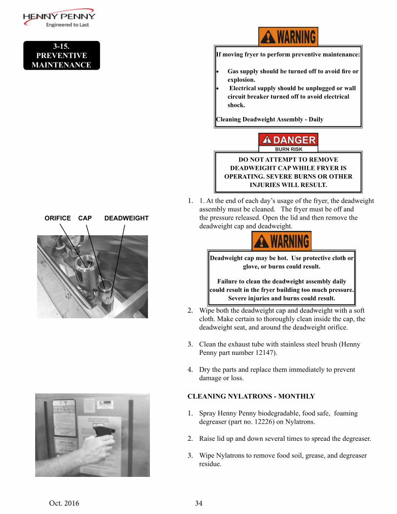
CLEANING NYLATRONS - MONTHLY
1. Spray Henny Penny biodegradable, food safe, foaming degreaser (part no. 12226) on Nylatrons.
2. Raise lid up and down several times to spread the degreaser.
3. Wipe Nylatrons to remove food soil, grease, and degreaser residue.
ORIFICE CAP DEADWEIGHT
If moving fryer to perform preventive maintenance:
• Gas supply should be turned off to avoid fire or explosion.
• Electrical supply should be unplugged or wall circuit breaker turned off to avoid electrical shock.
Cleaning Deadweight Assembly - Daily
Deadweight cap may be hot. Use protective cloth or glove, or burns could result.
Failure to clean the deadweight assembly daily could result in the fryer building too much pressure.
Severe injuries and burns could result.
DO NOT ATTEMPT TO REMOVE DEADWEIGHT CAP WHILE FRYER IS
OPERATING. SEVERE BURNS OR OTHER INJURIES WILL RESULT.
3-15. PREVENTIVE
MAINTENANCE
1. 1. At the end of each day’s usage of the fryer, the deadweight assembly must be cleaned. The fryer must be off and the pressure released. Open the lid and then remove the deadweight cap and deadweight.
2. Wipe both the deadweight cap and deadweight with a soft cloth. Make certain to thoroughly clean inside the cap, the deadweight seat, and around the deadweight orifice.
3. Clean the exhaust tube with stainless steel brush (Henny Penny part number 12147).
4. Dry the parts and replace them immediately to prevent damage or loss.

35Oct. 2016
REVERSING LID GASKET - EVERY 90 DAYS
Reversing the lid gasket helps to prevent early failure of the lid gasket and the loss of pressure during a Cook Cycle.
1. Raise the lid and remove the racks and carrier.
2. Grasping the lid handle, lift the front of the lid up until it stops in an upright position.
3. Using a thin blade screwdriver, pry out the gasket at th cor-ners. Remove the gasket.
4. Clean the gasket and gasket seat with hot water.
5. Rotate the gasket with the opposite side facing out.
Be sure the metal arm on the left side of the lid is in the vertical position holding the lid upright, or
severe injuries could result. (See photo at left.)
Check the gasket for any tears or nicks. If the gasket isdamaged, it needs to be replaced.
Install the four corners of the lid gasket. Smooth the gasket into place, working from the corners towards the
middle of each side.
CHECKING/CLEANING DILUTION BOX - ANNUALLY
Cleaning the dilution box helps to ensure the unit operates effciently and with few failures.
1. Make sure unit is off, and close and lock the lid.
3-15. PREVENTIVE
MAINTENANCE(CONT.)
Lid should be in locked down position. Failure to do so could result in personal injury.

36Oct. 2016
CLEANING SAFETY RELIEF VALVE - ANNUALLY
Do not use pipe wrench. Use thread sealant sparingly
1. Use a wrench to remove pressure gauge.
2. Use a wrench to loosen the valve from the pipe tee, turn counterclockwise to remove.
3. Clean the inside of the pipe tee with hot water.
SAFETY RELIEF VALVE
DILUTION SLOTS
2. Remove the back shroud of the fryer.
3. Clean the dilution box with a cloth or brush. Make sure the slots are free of debris. Replace the back shroud when finished.
Depending on the breading location and conditions within the kitchen area, the dilution slots may need to
be cleaned more often. See example below:
DO NOT ATTEMPT TO REMOVE THE SAFETY VALVE WHILE FRYER IS OPERATING, OR
SEVERE BURNS OR OTHER INJURIES WILL RESULT.
DO NOT DISASSEMBLE OR MODIFY THIS
SAFETY VALVE. TAMPERING WITH THIS VALVE COULD CAUSE SERIOUS INJURIES
AND WILL VOID AGENCY APPROVALS AND APPLIANCE WARRANTY.
3-15. PREVENTIVE
MAINTENANCE(CONT.)

37Oct. 2016
CLEANING BLOWER WHEEL - ANNUALLYThe blower wheel must be cleaned annually to ensure the unit operates efficiently and without failures.
1. Make sure unit is off, and close and lock the lid.
2. Remove the back shroud of the unit.
3. Using a Phillip’s-head screwdriver, remove the screw securing the flue to the blower.
4. Using a 3/8” socket or wrench, remove the 5 nuts securing the blower motor and pull motor from unit.
5. Clean the fins of the blower wheel, using a brush or straight blade screwdriver. Make sure the fins are clean of any debris.
Lid should be in locked down position. Failure to do so could result in personal injury.
Depending on the breading location and conditions within the kitchen area, cleaning the blower wheel may
need to be done more frequently.
3-15. PREVENTIVE
MAINTENANCE(CONT.)
Blower Motor
4. Immerse the safety relief valve in a soapy water solution for 24 hours. Use a 1:1 dilution rate. The valve cannot be disassembled. It is factory preset to open at 14-1/2 pounds of pressure. If it does not open or close, it must be replaced
LUBRICATING LID ROLLERS - ANNUALLYThe lid rollers, in the back of the fryer, should be lubricated at
least once a year, to allow the lid easy movement.
1. Remove the back shroud of the fryer.
2. Using spindle lube, part number 12124, place a small amount of lube on both top and bottom rollers. Make sure to lube both left and right rollers.
Turn the safety relief valve towards the rear of the fryer when reinstalling the relief valve.

38Oct. 2016
INSPECT COUNTER-WEIGHT CABLES-ANNUALLY Henny Penny 8 head fryers use two cables in the counter-weight mechanism that helps in the raising and lowering of the lid. Cables should be visually inspected yearly, either as part of a planned maintenance program or during a routine service call. Cables more than 10 years old should be replaced regardless of inspection results.
1. Using a Phillip’s-head screwdriver, remove top screw, but just loosen the lower screw on each side of the fryer, shown in Figure 1.
2. Lift out on the top of the rear cover and then lift up on it to clear loosen screw, circled in Figure 2.
Figure 1
Model 690 SN: AP802028 & Below
Models 690 SN AP082029 & Above
Figure 2
3-15. PREVENTIVE
MAINTENANCE(CONT.)
If lid becomes difficult to operate, stop using the fryer
and call for service. Cables need replaced.

39Oct. 2016
3. Inspect the counter-weight cables. If cables have cracks in the jacket, missing pieces in the jacket, or other obvious signs of wear, call for service to have both cables replaced.
NOT OK - REPLACECracks in jacket and obvious signs of wear.
OKNo signs of cracking or wear.
3-15. PREVENTIVE
MAINTENANCE(CONT.)

40Oct. 2016
1. Press and hold the FUNCTION button for 2 seconds.“REG PROGRAM” will show in the display, followed by “CODE”.
2. Press the code 1,2,3. “SELECT PRODUCT” will scroll across the display.
3. Press the appropriate product button (1-0) to identify what product you want to program.
4. “INT1” and “TIME” will flash on the left side of the display. The right side will show the starting time of the cook cycle and can be changed by pressing the appropriate numbers. Ex: Press 1,0,0,0 and “10:00” will flash on the right side of the display, setting the start time at 10 minutes.
5. After the time is set, press and release the FUNCTION button and “INT1” and “TEMP” will flash on the left side of the display. The right side will show the starting temperature and can be changed by pressing the appropriate numbers. Ex: Press 2,5,0 and “250° F” will show on the right side of the display, setting the start temperature at 250° Fahrenheit.
6. After the temperature is set, press and release the FUNCTION button; and “INT1” and “PRESS” will flash on the left side of the display. Press any of the product buttons (1-0) to turn the pressure on or off.
7. After the pressure is set, press and release the FUNCTION button; and “INT1”, “LOAD”, and “COMP” will flash on the left side of the display. The factory preset load compensation value shows in the right side of the display.
For gas fryers, when the power is interrupted to the control it re-starts the lighting sequence. Failure to
re-light would result in a error which would require the user to turn the unit off and then back on.
If no buttons are pressed within approximately 1 minute while in the Program Mode, the controls will
revert back to the Cook Mode.
3-16.PROGRAMMING

41Oct. 2016
3-16.PROGRAMMING
(CONT.)
8. After the load compensation, press and release the FUNCTION button. “PROP” and “CONTROL” show on the left side of the display, and the factory preset proportional control temperature shows on the right side of the display.
9. After the proportional control, press and release the FUNCTION button. “ALM 1” and “TIME” flash on the left side of the display, and the first alarm time shows on the right side of the display. To change the time the alarm sounds, press the appropriate product buttons to set the time. Ex: Press 1,0,0,0. “10:00” will flash on the right side of the display, which means when the timer counts down 10 minutes, an alarm will sound.
10. After the alarm is set, press and release the FUNCTION button. “ALM 1”, “SELF-”, and “CANCEL” flash on the left side of the display, and “YES” or “NO” shows on the right side of the display. The yes and no can be toggled by pressing any of the product buttons (l-0). YES means the alarm tone will automatically stop after several beeps. NO means someone must manually press the appropriate product button to stop the alarm tone.
11. Repeat steps 9 and 10 for alarms 2 and 3.
12. After alarm 3 is set, press and release the FUNCTION button. “FILTER” and “CYCLES” show on the left side of the display, and the filter cycle value is on the right side of the display. The value is the number of cook cycles that must be completed before the control signals the operator that the shortening needs filtered.

42Oct. 2016
13. After the filter value is set, press and release the FUNCTION button. “EOC” and “EXIT” flash on the left side of the display, and “COOL” shows on the right side of the display. The end-of-cycle (EOC) exit point can be set to COOL, SETP, or FITR by pressing any of the product buttons (EOC). At the end of a cook cycle, the controls can be set to return to: COOL, the setpoint temperature, or to signal the operator to filter the shortening.
14. After the end-of-cycle setpoint is set, press and release the FUNCTION button. “HEAD” and “COUNT” flashes on the left side of the display, and a number shows on the right side of the display. The number on the right is the number of head of chicken to be cooked when that product button is pressed. The number can be changed by pressing the appropriate product button.
15. To program a second interval, press and release the SCAN button while in the Time mode of the first mode. “INT2” and “TIME” will flash on the left side of the display. Then follow the steps above, starting with step 4.
3-16.PROGRAMMING
(CONT.)
Another product can be programmed while in the program mode by following these procedures:
Press and hold the SCAN button at any time while in the Program mode, and the display will scroll
“SELECT PRODUCT”. Then press any of the product buttons (1-0), and that product can be programmed.
REVIEW USAGE
1. Press and hold the FUNCTION button for 2 seconds until “REG PROGRAM” shows in the display. As soon as “REG PROGRAM” shows in the display, press and release the FUNCTION button one time until “REVIEW USE” shows in the display.
2. “DAILY” shows in the display. Press any of the product buttons to view the usage of that product. Press and hold the FUNCTION button to exit Special Program mode.
3-17.SPECIAL
PROGRAM MODE

43Oct. 2016
3-17.SPECIAL
PROGRAM MODE(CONT.)
RESET USAGE
1. Press and hold the FUNCTION button for 2 seconds until “REG PROGRAM” shows in the display. As soon as “REG PROGRAM” shows in the display, press and release the FUNCTION button two times until “RESET USE” shows in display.
2. When “CODE” shows in the display, press 1,3,5. “DAILY” will show in the display; then press any of the product buttons to reset them to 0.
FACTORY PRESETS (F/C, GAS/ELECTRIC, SPEAKER VOLUME, SPEAKER FREQUENCY, CODES, INITIALIZE SYSTEM)
1. Press and hold the FUNCTION button for 2 seconds until “REG PROGRAM” shows in the display. As soon as “REG PROGRAM” shows in the display, press and release the FUNCTION button three times until “FAC PRESET” shows in the display.
2. When “CODE” shows on the display, enter 2,9,5,7. “DEG” and “MODE” flash in the display. Press any of the product buttons to toggle from “ºF” to “ºC”, and vice versa.
3. Press and release the FUNCTION button, and “TYPE” and “FRYR” flash in the display. Press any of the product buttons to toggle from “GAS” to “ELEC”, or vice versa.
4. Press and release the FUNCTION button twice, and “SPKR” and “VOL” flash in the display. The volume can be changed from 01 to 10, 10 being the loudest.
5. Press and release the FUNCTION button three times, and“SPKR” and “FREQ” will flash in the display. The frequency can be set from 100 to 2000.
6. Press and release the FUNCTION button 10 times, and “INITIALIZE SYSTEM” scrolls across the display. Press and hold any of the product buttons and the display will count down from 5. Once the display counts down, release the product button, and the control will set factory-preset parameters into the controls
Before attempting to change the other modes in the Factory Preset mode, please call the Henny Penny Technical Service Department at 800-417-8405 or
1-937-456-8405.

44Oct. 2016
TECH I/O MODE
1. Press and hold the FUNCTION button for 2 seconds until“REG PROGRAM” shows in the display. As soon as “REG PROGRAM” shows in the display, press and release the FUNCTION button four times until “TECH I-O” shows in the display.
2. When “CODE” shows in the display, press 2,4,6 (1,7,7,6 for CE units). “HEAT”, “PRESSURE”, and “PUMP” will show alternately, in the display. Also, the LEDs over 1, 2, and 3 will flash alternately.
3. To test the heat circuit, press and hold the 1 button.
4. To test the pressure system, press and hold the 2 button.
5. To test the pump system, press and hold the 3 button. CE Only:
6. To test the blower, press and hold the 4 button.
7. To test the module, press and hold the 5 button.
3-17.SPECIAL
PROGRAM MODE(CONT.)
To test the heat output on CE units, the blower and modules must first be turned on.
APPLIANCE TESTPress and hold the FUNCTION button for 2 seconds until“REG PROGRAM” shows in the display. As soon as “REG PROGRAM” shows in the display, press and release the FUNCTION button five times until “APPL TEST” shows in the display.
With the power switch on, the display will show “CURR=”, along with the time it took the unit to heat from 250º to 300º F (121º to 149º C) . This is normally recorded from the initial heat up in the morning.

45Oct. 2016
HEAT CONTROL1. Press and hold the FUNCTION button for 2 seconds until
“REG PROGRAM” shows in the display. As soon as “REG PROGRAM” shows in the display, press and release the FUNCTION button six times until “HEAT CNTRL” shows in the display.
2. When “CODE” shows in the display, press 1,2,3,4. “MELT”,“EXIT”, and “TEMP” will flash in the display, along with the shortening temperature at which the unit will exit the melt cycle. This should be set at 180ºF (82ºC), and should not be changed until the factory is consulted.
3. Press and release the FUNCTION button, and “MELT”,“CYCLE”, and “100s” show alternately in the display, along with the period (pulse) length of “4000”. This should not be changed until the factory is consulted.
4. Press and release the FUNCTION button twice and “MELT”, “ON-”, “TIME”, and “100s” show alternately in the display, along with the length of time the heat is on. This should be set at 1700, and should not be changed until the factory is consulted.
5. Press and release the FUNCTION button three times, and “COOL”, “SET-”, and “POINT” show alternately in the display, along with the temperature at which the control exits the melt cycle. This is set at 250ºF (121ºC), and should not be changed until the factory is consulted.
6. Press and release the FUNCTION button four times, and “AUTO” and “IDLE” show alternately in the display, along with “OFF”. This should not be changed until the factory is consulted.
7. Press and release the FUNCTION button five times, and “AUTO”, “IDLE”, and “MMSS” shows alternately in the display, along with 0:00. This should not be changed until the factory is consulted.
8. The last three functions in the Heat Control mode are used by the factory only, and should not be changed.
3-17.SPECIAL
PROGRAM MODE(CONT.)


47Oct. 2016
4-1.TROUBLESHOOTING
GUIDE
DO NOT OPERATE UNIT IF PRESSURE GAUGE SHOWS HIGH PRESSURE CONDITIONS. SEVERE INJURIES AND BURNS WILL RESULT. IMMEDIATELY PLACE THE POWER/ PUMP SWITCH IN THE OFF POSITION, WHICH RELEASES THE PRESSURE BY ALLOWING THE UNIT TO COOL. DO NOT RESUME USE OF UNIT UNTIL CAUSE OF HIGH PRESSURE HAS BEEN FOUND AND CORRECTED.
SECTION 4: TROUBLESHOOTING
Problem Cause CorrectionPower switch on but fryercompletely inoperative
• Open circuit • Plug fryer in• Check breaker or fuse at wall
Pressure not exhausting atend of Cook Cycle
• Solenoid or exhaust line clogged
• Turn off and allow fryer to cool to release the pressure in frypot; have all lines, solenoid, and exhaust tank cleaned
Operating pressure too high • Deadweight clogged • Turn off and allow fryer to cool to release the pressure in frypot; clean deadweight; see Preventive Maintenance Section
More detailed troubleshooting information is available in the Technical Manual, available at www.hennypenny.com, or 1-800-417-8405 or 1-937-456-8405.
Pressure does not build • Not enough product in frypot\• Metal shipping spacer not
removed from deadweight• Pressure not programmed• Lid gasket leaking
• Place full capacity product in frypot when using fresh shortening
• Remove shipping spacer; see Unpacking Instructions Section
• Check programming• Reverse or replace lid gasket
Shortening not heating • Gas valve knob turned to the OFF position
• Drain valve open• High temperature limit tripped
• Make sure gas control valve knob is turned to the ON position
• Close drain valve• Reset high temperature limit; see • Operating Components Section
Foaming or boiling over • See Boil-Over chart on fryer and information in this manual
• Follow Boil-Over procedures from chart
Shortening not draining • Drain valve clogged • Push cleaning rod through open drain valve
Filter motor won’t run • Motor overheated • Reset motor; see Filter Pump Motor Protector-Manual Reset Section
48Oct. 2016
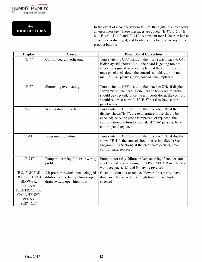
In the event of a control system failure, the digital display shows an error message. These messages are coded: “E-4”,“E-5”, “E-6”, “E-32”, “E-41” and “E-71”. A constant tone is heard when an error code is displayed, and to silence this tone, press any of the product buttons.
Display Cause Panel Board Correction“E-4” Control board overheating Turn switch to OFF position, then turn switch back to ON;
if display still shows “E-4”, the board is getting too hot; check for signs of overheating behind the control panel; once panel cools down the controls should return to nor-mal; if “E-4” persists, have control panel replaced
“E-5” Shortening overheating Turn switch to OFF position, then back to ON; if display shows “E-5”, the heating circuits and temperature probe should be checked; once the unit cools down, the controls should return to normal; if “E-5” persists, have control panel replaced
“E-6” Temperature probe failure Turn switch to OFF position, then back to ON; if the display shows “E-6”, the temperature probe should be checked; once the probe is repaired, or replaced, the controls should return to normal; if “E-6” persists, have control panel replaced
“E-41” Programming failure Turn switch to OFF position, then back to ON; if display shows “E-41”, the control should be re-initialized (See Programming Section) if the error code persists, have control panel replaced
“E-71” Pump motor relay failure or wiring problem
Pump motor relay failure or Replace relay if contacts are stuck closed; check wiring on POWER/PUMP switch, or at wall receptacle; L1 and N may be reversed
“E32, FAN FAIL ERROR, CHECK
BLOWER, CLEAN
DILUTIONBOX, CALL HENNY
PENNY SERVICE”
Air pressure switch open; clogged dilution box or faulty blower; open drain switch; open high limit
Clean dilution box or replace blower if necessary; have drain switch checked; reset high limit or have high limit checked
4-2.ERROR CODES

49Oct. 2016
CE Only - Along with the error codes from page 4-2, CE units have the following self-diagnostic error codes:
“E-10” High limit Reset the high limit by manually pushing up on the red reset button; if the high limit does not reset, the high limit must be replaced
“E-15” Drain switch Close the drain, using the drain valve handle; if dis-play still shows “E-15”, have the drain microswitch checked
“E-20A” Air pressure switch failure Press the timer button to try the ignition process again, and if “E-20A” persists, call Henny Penny’s Service (stuck closed) Department
“E-20B” Draft fan or air pressure switch failure (stuck open)
Press the timer button to try the ignition process again, and if “E-20B” persists, call Henny Penny’s Service Department
“E-20C” Left gas module failure Press the timer button to try the ignition process again, and if “E-20C” persists, call Henny Penny’s Service Department
“E-20D” Right module failure Press the timer button to try the ignition process again, and if “E-20D” persists, call Henny Penny’s Service Department
“E-20E” Both modules failure Press the timer button to try the ignition process again, and if “E-20E” persists, call Henny Penny’s Service Department
“E-20F” Left module no flame sense Press the timer button to try the ignition process again, and if “E-20F” persists, call Henny Penny’s Service Department
“E-20G” Right module no flame sense Press the timer button to try the ignition process again, and if “E-20G” persists, call Henny Penny’s Service Department
“E-20H” Both modules no flame sense Press the timer button to try the ignition process again, and if “E-20H” persists, call Henny Penny’s Service Department
4-2.ERROR CODES
Display Cause Panel Board Correction


51April 2017
APPENDIX A: ANNUAL PREVENTIVE MAINTENANCE
This appendix contains the annual preventive maintenace checklist.

8-Head Pressure Fryer Annual Inspection Checklist
INSPECTION # OK CLEAN REPLACE
Assess Frypot and Frame (remove rear cover and both side panels)
1 * Inspect fry pot for leakage
2 Inspect that the fryer sits level. Inspect casters and ensure fryer frame is not cracked or bent.
Rear of Fryer and Pressure System
3 * Inspect electrical cord and plug.
4 * Inspect gas line, quick disconnect and tether (690 only).
5 * Inspect the lid cables following all instructions.
6
Check that the counterweight frame hangs level. Clean and adjust lid magnet (580 only)
7 Inspect and lubricate lid carriage rollers and cable pulleys (rear of fryer). Lid should move up and down freely.
8 Remove and clean blower wheel (690 only)
9 Check Dilution Box, clean as needed (690 only)
10 Clean Nylatron slides
11 Check that the condensation box drain line, dead weight tube, pressure release tubing is free and clear from clogs. Also that each is not damaged or leaking.
12 Remove solenoid valve, clean and reassemble (rear of fryer, 580, 590 and 690s newer than Feb 2008. Above counter top for 690s older than February 2008).
13 Disassemble condensation box and clean, seal seams w/silicone
14 Inspect Deadweight including orifice, O-ring, cap, and weight) ensure they are in good working condition.
15 Verify the existing pressure gauge rests at zero and is free and clear from obstructions.
16 Clean Safety Relief Valve –
17 Inspect the steam exhaust stack / hose.

8-Head Annual Inspection Checklist
Filter Components and Drain Oil
18 Clean air solenoid valve near filter pump motor - 690 only
19 Verify the drain valve handle microswitch is in working condition
20 Inspect that the drain pan is empty, all components present (filter screen, clips, crumb catcher, standpipe, lid) and it is assembled correctly.
21 Test filter pump motor to ensure operation
22 Drain oil to drain pan. Ensure no drain obstructions.
Heat System
23 Tighten heating element spreader bars and high limit bracket – 580 and 590 only
24 Inspect temperature probe, verify it is not bent or damaged. Check the insertion depth of the probe with a gauge – adjust if necessary
25 Clean Burners (690 only)
26 Inspect and clean pilot assemblies. Adjust pilots if necessary (690 only)
27 Inspect for excessive oil migration behind the control board
28 * Inspect the high limit following all instructions.
Pump Oil / Heat Oil
29 Test filtration system when pumping oil back up – no obstructions, leaks or excessively slow pumping.
30 Check amp draw of heating elements are consistent and when added up, match the amp draw listed on the data plate. 580 and 590 only
31 Check that manifold pressure matches the data plate and gas type of the fryer (690 only)
Pressure system
32 * Inspect Lid Handle Rollers following all instructions
33 Inspect cam slide fillers (each side of lid cover)
34 Inspect front lid latch – adjust if necessary
35 * Remove lid cover and inspect lid components – Make sure lid components are not damaged, missing or in disrepair. – Remove and clean excessive oil from lid and components, clean vent holes and Lubricate Lid Locking Mechanism.
36 Inspect pressure pads. Rotate if excessively worn, replace if both sides excessively worn
37 Inspect the lid gasket. Reverse if wear is acceptable

8-Head Annual Inspection Checklist
Pressure test
38 * Perform a pressure test with at least 4-Head OR following all instructions. Verify lid locks under at pressures less than 3psi and then unlocks only when pressure drops below 1.7 psi Verify in this test if pressure is regulating in the green zone. Verify that all pressure releases prior to the timer reaching 0:00. This will help to identify if there is still any pressure release and deadweight tubing obstructions.
During Pressure Test
39 Verify pressure gauge is functioning in a similar range as the calibrated test fixture.
40 Inspect the oil return check valve for leaks while under pressure. Verify there is no oil leaking back through the oil return plumbing to the drain pan while under pressure.
41 Inspect the drain valve for leaks while under pressure.
General Fryer
42 Verify all labels are in place and legible on fryer.
*Critical Item - Take fryer out of service until repaired What are the tools required prior to doing this job
Temperature probe depth gauges
Pipe snake
Manometer
Amp Clamp
Imperial size Socket Set
Imperial size set of hex key wrenches
Full range pliers set from needle nose to 12” large slip joint
Phillips and flat blade screwdriver set
Pipe wrenches 8 – 12”
wire stripping tool
wire cutter
crimping tool
Adjustable wrench set 8 – 12”
Open end wrench set (imperial sizes)

8-Head Annual Inspection Checklist
What parts should I take with me prior to doing this job?
Safety relief valve (One per fryer)
Pressure Gauge
Lid Cables
Pressure pads
Lid Gasket
Solenoid Rebuild kit
Temperature probe
Spindle Lube
Pipe thread sealant
Towels
Steel and Teflon sleeve fittings
Condensation box hose
Check valve
Dead weight cap O-ring
Roller spindles for carriage???
Lid handle rollers
Nylatron slides
Side cam fillers
Lid latch
Pilot assemblies
Flame sensor
Power cord for 690
Plumbing elbows
High limit
Drain switch
Splice connectors
Copyright © 2017 Henny Penny Corporation. All rights reserved. Henny Penny and the Henny Penny logo are registered trademarks of Henny Penny Corporation in the United States and other
countries.


*FM05-009-L Henny Penny Corp., Eaton, Ohio 45320, Revised 04-01-17
Henny Penny CorporationP.O.Box 60Eaton,OH 45320
1-937-456-84001-937-456-8402 Fax
Toll free in USA1-800-417-84171-800-417-8434 Fax
www.hennypenny.com