Embed Size (px)
Citation preview

Operating Manual Saddle-mount fan unit with tank trailer
GSG-AN2 (two rows)
LIPCO GmbH Am Fuchsgraben 5b D-77880 Sasbach Tel. +49 (0) 7841 6068-0 Fax +49 (0) 7841 6068-10 email [email protected] Internet http://www.lipco.com/
Operating Manual Saddle-mount fan unit with tank trailer GSG-AN2
2 - 68 010550-20-E BA GSG-AN2 / 14.02.2012

Operating Manual Saddle-mount fan unit with tank trailer GSG-AN2
3 - 68 010550-20-E BA GSG-AN2 / 14.02.2012
Introduction Dear Customer: Thank you for choosing a LIPCO Saddle-mount fan unit with tank trailer GSG-AN2. We are confident that you will be satisfied with our product. In order to achieve maximum performance from your new LIPCO Saddle-mount fan unit with tank trailer GSG-AN2 over an extended period, please follow the instructions in this operating manual closely. This will help you to prevent any damage and also to prevent accidents that could result from failure to comply with the manual and for which LIPCO can assume no liability. This operating manual is an essential component of the machine and therefore must always be included when the machine is sold, also if it is sold to third parties. By carefully storing the operating manual in a safe place, both you and the operator will have a comprehensive reference work at hand. Note: The illustrations, descriptions and data contained in this operating manual are not binding. LIPCO reserves the right to make changes at any time, without prior notice.

Operating Manual Saddle-mount fan unit with tank trailer GSG-AN2
4 - 68 010550-20-E BA GSG-AN2 / 14.02.2012
Table of contents Page 1. Authorized use ................................................................................................... 6 2. Warnings on the machine .................................................................................. 7 3. General safety regulations ................................................................................. 8 4. Safety information for handling plant protection agents .................................... 9 5. Accident prevention ......................................................................................... 11 6. Construction details of the GSG-AN2 / standard equipment ........................... 12 7. Construction details of the GSG-AN2 / special equipment .............................. 12 8. Advantages of LIPCO tunnel spray technology ............................................... 13 9. Technical data for the GSG-AN2 ..................................................................... 14 10. Construction details of the LIPCO tank trailer / standard accessories ............ 15 11. Construction details of the LIPCO tank trailer / special accessories ............... 15 12. Technical data for LIPCO tank trailer ............................................................... 15 13. Components of the GSG-AN2 ......................................................................... 16 13.1. Filter ................................................................................................................. 16 13.2. Fan width adjustment ....................................................................................... 17 13.3. Tanks of the GSG-AN2 .................................................................................... 18 13.4. The various multiple valves of the LIPCO GSG-AN2: ..................................... 19 14. Preparation ...................................................................................................... 21 15. Attachment to the towing vehicle ..................................................................... 22 16. Attachment of the universal joint shaft ............................................................. 24 17. Attaching the LIPCO tank trailer ...................................................................... 26 18. Driving on roads with the GSG-AN2 ................................................................ 27 19. Operating the LIPCO GSG-AN2 ...................................................................... 28 19.1. Determining the amount of spray liquid needed .............................................. 28 19.2. Checking the driving speed ............................................................................. 28 19.3. Calculation of the driving speed ....................................................................... 29 19.4. Nozzle selection and distribution quantity........................................................ 30 19.5. Checking the liquid discharge .......................................................................... 31 19.6. Nozzle adjustment during operation ................................................................ 33 19.7. Spray nozzle adjustment ................................................................................. 34 19.8. Recycling device .............................................................................................. 35 20. Setting the LIPCO GSG-AN2 ........................................................................... 37 20.1. Calculation of the liquid discharge ................................................................... 37 20.2. Calculation of the required plant protection agent/spray ................................. 38 20.3. Intervals for checking the dosing and distribution accuracy of the LIPCO GSG-
AN2 .................................................................................................................. 39 20.4. Which plant protection agents can be used in the LIPCO GSG-AN2 ? ........... 39 21. Conducting test spraying ................................................................................. 40 22. Preparation of spraying liquid .......................................................................... 41 23. Emptying the GSG-AN2 after use .................................................................... 43 24. Residual volume .............................................................................................. 44 25. Interruption of spraying process ...................................................................... 44 26. Cleaning of the GSG-AN2 after use ................................................................ 46 27. Maintenance .................................................................................................... 49 28. Machine inspection .......................................................................................... 53 28.1. Pressure check ................................................................................................ 53 28.2. Flow rate check ................................................................................................ 53 29. Troubleshooting ............................................................................................... 54 30. Storing the machine ......................................................................................... 56 31. Warranty .......................................................................................................... 58 32. Functional diagram GSG AN2 ......................................................................... 59 33. Electric diagram for GSG-AN2 ......................................................................... 60
Operating Manual Saddle-mount fan unit with tank trailer GSG-AN2
5 - 68 010550-20-E BA GSG-AN2 / 14.02.2012
34. Hydraulic diagram for GSG-AN2 ..................................................................... 61 35. Combination matrix for GSG-AN2 ................................................................... 62 36. Notes ............................................................................................................... 63 37. EG Declaration of conformity ........................................................................... 67

Operating Manual Saddle-mount fan unit with tank trailer GSG-AN2
6 - 68 010550-20-E BA GSG-AN2 / 14.02.2012
1. Authorized use
The LIPCO Saddle-mount fan unit with tank trailer GSG-AN2 with recycling technology is intended for spraying plant protection agents for vineyards, rose and berry plantations and similar cultures. Any other use is deemed not authorized. The manufacturer will not be liable for damages resulting from unauthorized use; the user will be solely responsible for all risks in this case. Authorized use also includes compliance with the manufacturer’s operating, maintenance and repair instructions. The operator is responsible for compliance with applicable accident prevention regulations, in addition to the generally recognized safety, occupational health and traffic safety regulations. Unauthorized modifications to the LIPCO Saddle-mount fan unit with tank trailer GSG-AN2 will release the manufacturer from liability for resulting damages.
Note for use on public roads Before driving on public roads and paths, make sure that the combination of tractor and LIPCO Saddle-mount fan unit with tank trailer GSG-AN2 or other combined equipment complies with the applicable traffic regulations (maximum gross weight, maximum axle loads, lights, warning signs, etc.). It may be necessary to transport the LIPCO Saddle-mount fan unit with tank trailer GSG-AN2 on a flatbed truck.
Note The LIPCO Saddle-mount fan unit with tank trailer GSG-AN2 is also referred to in this operating manual only as LIPCO GSG-AN2.

Operating Manual Saddle-mount fan unit with tank trailer GSG-AN2
7 - 68 010550-20-E BA GSG-AN2 / 14.02.2012
2. Warnings on the machine
Before operating the machine, always read the operating manual and comply with all safety instructions!
Always shut off the motor and remove the ignition key when performing maintenance or repairs!
Danger of parts being catapulted while drive unit is in operation – maintain safety clearance!
Operate machine only at the specified speed (max. 540 rpm)!
Danger of poisoning – never climb into container!
Operating Manual Saddle-mount fan unit with tank trailer GSG-AN2
8 - 68 010550-20-E BA GSG-AN2 / 14.02.2012
3. General safety regulations
The operation of mobile plant protection units is associated with certain risks. Therefore, you must comply with the following safety regulations:
Before operating the machine, always read the operating manual and comply with all safety instructions!
Never remove or modify safety devices!
Never enter the area beneath the machine for repairs or inspections unless the machine is secured!
Prior to performing maintenance or care, make sure that the machine is switched off!
Always maintain safety clearances!
Caution! Do not enter the work area while the universal joint shat is rotating! There is an increased risk of accident in case of contact. For your safety, do not wear loose clothing or accessories (e.g. scarves)!
The LIPCO GSG-AN2 may be operated, maintained and repaired only be personnel who are specially trained and are aware of the risks involved!
The operator is responsible for compliance with applicable accident prevention regulations, in addition to the generally recognized safety, occupational health and traffic safety regulations!
The warning and information signs on the machine provide important information for safe operation; compliance with these warnings will increase your safety!
Persons not involved must keep out of the work area of the machine.
Keep children away from the LIPCO GSG-AN2 and spray.
Operate machine only at the specified speed (max. 540 rpm)!

Operating Manual Saddle-mount fan unit with tank trailer GSG-AN2
9 - 68 010550-20-E BA GSG-AN2 / 14.02.2012
4. Safety information for handling plant protection agents
Do not use plant protection agents that tend to gum up or congeal – they have a negative effect on spraying.
Before applying heat (welding, soldering, etc.) in order to repair the tunnel spray unit or attachments that come into contact with the plant protection agent, these units must be cleaned thoroughly with water.
Standard safety devices may not be removed or modified.
Damaged safety devices must be replaced by new ones.
Damaged seals and shut-off devices must be replaced.
Persons who come into contact with plant protection agents or who work with the tunnel spray unit must protect themselves with suitable protective gear against contamination from the plant protection agents. (safety gloves, etc.)
Always comply with the regulations of the plant protection agent manufacturer and of the trade association. AID brochure 1042 (2) provides information on the safe handling of plant protection agents.
Relevant literature is available from: Evaluation and information service for nutrition, agriculture and forestry (AID), P.O. Box 20 02 53, 53173 Bonn. AID brochure 2079 (1): Filling plant protection agent machines: caution in taking water from the drinking water supply and public waters. AID brochure 1042 (2): Caution in handling herbicides and plant protection agents.
Operating Manual Saddle-mount fan unit with tank trailer GSG-AN2
10 - 68 010550-20-E BA GSG-AN2 / 14.02.2012
Do not eat, drink or smoke when working with herbicides and plant protection agents.
Wash hands and face thoroughly with soap and water after every contact with spraying equipment or spray liquid and after completion of work.

Operating Manual Saddle-mount fan unit with tank trailer GSG-AN2
11 - 68 010550-20-E BA GSG-AN2 / 14.02.2012
5. Accident prevention Most accidents that occur during use, maintenance or transport are caused by failure to comply with the simplest basic rules. Therefore it is important that all persons involved with use of the machine are aware of and comply with the following rules:
In order to achieve maximum performance from the LIPCO GSG-AN2 it must be in proper working order. Maintenance and repair may be performed only by trained personnel. Replacement parts must fulfill the minimum technical specifications required by the manufacturer! This is ensured only by the use of LIPCO original replacement parts!
Before each use, check the trailer hitch bolts on the three-point mount and all nuts and bolts!
Exercise special caution when using roads or paths, e.g. for turning the entire tunnel spray unit.
Always shut off the motor and remove the ignition key when performing maintenance or repairs!
During work and transport on roads do not transport objects or persons on the machine!
Operate machine only with drive unit fully protected, i.e. universal joint shaft completely covered and additional protection on tractor and GSG. Make sure that the universal joint shaft connections lock securely into place!
The machine should be on a level surface or a stable support during all work on the machine!
When working on the machine in raised position, always secure by mechanical means using suitable supports!

Operating Manual Saddle-mount fan unit with tank trailer GSG-AN2
12 - 68 010550-20-E BA GSG-AN2 / 14.02.2012
6. Construction details of the GSG-AN2 / standard equipment
frame with double-coat paint RAL 6011
cross-flow fan unit width adjustment (infinitely variable / common or single action) with hydraulic cylinder. Operation via electro-hydraulic control block.
4 hydraulic driven cross-flow fans, equipped with collecting tray and hydro injector for the leading back of the unused liquid - minimum operating pressure 5 bar required for suction
one V4A nozzle tube each integrated in the cross-flow fans,
with 5 drip-stop rotary nozzle bodies with flat fan venturi nozzles (AVI 80° green – or other output quantities on request) – individually adjustable
pressure (80 mesh), suction (50 mesh) and recycling filter (50 mesh)
full electrical control: Nozzles, recycling, pressure and agitator can be controlled via control box on tractor, manometer built into control box
electro-hydraulic control block for adjustment of the fan width and the fan control
100 l fresh water tank with 3-way tap for switching for cleaning the equipment
160 l pump, 16 bar
universal joint shaft
7. Construction details of the GSG-AN2 / special equipment
The following special equipment is available:
Row width 2,40 m / 3,20 m
Width adjustment 1.30 m instead of 1.10 m (standard)
Tank 1500 l instead of 1000 l
Working lights between fans
3-way tap with quick-release coupler and 2.50 m hose for external suction
Electrical monitoring unit with display (output l/min., speed and effective output in liters)
Electrical monitoring and control unit type SPRAYDOS, with digital display, incl. on board computer and boom section switches
Other nozzles
2 agent-sprayer type BS 2

Operating Manual Saddle-mount fan unit with tank trailer GSG-AN2
13 - 68 010550-20-E BA GSG-AN2 / 14.02.2012
8. Advantages of LIPCO tunnel spray technology
The fan design causes a higher spray concentration and therefore a more intensive deposition of spray on the plants.
Negative effects of natural wind outside of the fan unit on the spraying are kept to a minimum.
Spray that is not deposited on the plants is collected in a pan and filtered for re-use.
The spray nozzles can be switched on and off based on the height of the foliage wall for optimum use of spray.

Operating Manual Saddle-mount fan unit with tank trailer GSG-AN2
14 - 68 010550-20-E BA GSG-AN2 / 14.02.2012
9. Technical data for the GSG-AN2
GSG-AN2 standard
Weight empty without trailer tank kg 500.-
Required drive power kW
Pump type AR 160 bp
Number of fans 4
Row width – standard m 1.70 – 2.40
Width adjustment standard m 0.20 – 1.10
Required pump capacity l / min 40
Main external dimensions:
Abbildung zeigt TSG-A, zweizeilige Ausführung
Typ L (m) B (m) H (m)
GSG-AN2 3,50 2,30 2,10
Operating Manual Saddle-mount fan unit with tank trailer GSG-AN2
15 - 68 010550-20-E BA GSG-AN2 / 14.02.2012
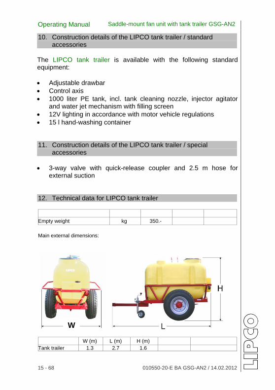
10. Construction details of the LIPCO tank trailer / standard
accessories The LIPCO tank trailer is available with the following standard equipment:
Adjustable drawbar
Control axis
1000 liter PE tank, incl. tank cleaning nozzle, injector agitator and water jet mechanism with filling screen
12V lighting in accordance with motor vehicle regulations
15 l hand-washing container 11. Construction details of the LIPCO tank trailer / special
accessories
3-way valve with quick-release coupler and 2.5 m hose for external suction
12. Technical data for LIPCO tank trailer Empty weight kg 350.-
Main external dimensions:
W (m) L (m) H (m) Tank trailer 1.3 2.7 1.6
W

Operating Manual Saddle-mount fan unit with tank trailer GSG-AN2
16 - 68 010550-20-E BA GSG-AN2 / 14.02.2012
13. Components of the GSG-AN2
13.1. Filter
Suction filter – mesh width 0.508 mm:
The suction filter is under the two recycling filters. (Fig. 1)
The filter insert should be check several times daily for dirt and cleaned, if necessary.
Fig. 1
Pressure filter 1 – mesh width 0.3175 mm: The pressure filter is located
between the shut-off motors. (Fig. 2)
The filter insert should be check several times daily for dirt and cleaned, if necessary.
Drain valve for draining contaminated spray liquid.
Fig. 2
Pressure filter 2 – mesh width 0.3175 mm: Pressure filters 2 in circuit
close to spray nozzles
The filter inserts must be checked several times daily and cleaned, if necessary. (Fig. 3)
Fig. 3

Operating Manual Saddle-mount fan unit with tank trailer GSG-AN2
17 - 68 010550-20-E BA GSG-AN2 / 14.02.2012
Recycling filter – mesh width 0.508 mm: The two recycling filters in the
return flow of the recycled spray must be checked several times daily and cleaned, if necessary. (Fig. 4)
Fig. 4
13.2. Fan width adjustment
The fan width is adjusted manually from the tractor via hydraulic, double-action control valves. (Fig. 5)
Hydraulic cylinder for tunnel width adjustment.
Fig. 5

Operating Manual Saddle-mount fan unit with tank trailer GSG-AN2
18 - 68 010550-20-E BA GSG-AN2 / 14.02.2012
13.3. Tanks of the GSG-AN2
Spray liquid tank:
Spray liquid tank Fill level indicator
Fig. 6
Fresh water tank:
Fresh water tank for cleaning the LIPCO GSG-AN2 after completion of spraying. (Fig. 7)
Caution: Do not fill the fresh water tank with spray liquid!! Do not drink from the tank!!
Fig. 7
Hand washing tank
-{}-
The hand washing tank must be filled with fresh water only and is used for washing the operator’s hands after spraying. (Fig. 8) Hand washing tank on the back of the tank trailer.
Caution: Do not fill the hand washing tank with spray liquid!! Do not drink from the tank!!
Fig. 8

Operating Manual Saddle-mount fan unit with tank trailer GSG-AN2
19 - 68 010550-20-E BA GSG-AN2 / 14.02.2012
13.4. The various multiple valves of the LIPCO GSG-AN2:
Fig. 9 Fig. 10
Function of the 3-way valve (Fig. 9)
Position: “Suction tank” Liquid is pumped from the spray liquid tank / fresh water tank to the nozzles in the tunnel walls.
Position: “Clean suction filter” Spray liquid circuit is blocked, suction filter can be removed and cleaned.
Position: “Empty tank” Spray liquid tank can be emptied.
Place the collector beneath the valve and dispose of the collected spray agent in accordance with Federal Biological Research Institute (BBA) regulations.
1
2

Operating Manual Saddle-mount fan unit with tank trailer GSG-AN2
20 - 68 010550-20-E BA GSG-AN2 / 14.02.2012
Function of the front 2-way valve (Fig. 10-1)
Position: “Machine cleaning” Pump conveys fresh water from the fresh water tank through the spray nozzles to the injectors and via the recycling filter back into the spray liquid tank.
Position: “Suction tank” Pump conveys spray liquid from the spray liquid tank to the spray nozzles.
Function of the front 2-way valve (Fig. 10-2)
Position: “Machine cleaning” Pump conveys fresh water from the fresh water tank through the spray nozzles to the injectors and via the recycling filter back into the spray liquid tank.
Position: “Suction tank” Pump conveys spray liquid from the spray liquid tank to the spray nozzles. The second 2-way valve is situated between pressure regulator and pump – see also functional diagram.
Note: Both 2-way valves must always be in some position, either for spaying or for cleaning.
That means, e.g. both valves in position “suction tank” or in position “machine cleaning”.
Operating Manual Saddle-mount fan unit with tank trailer GSG-AN2
21 - 68 010550-20-E BA GSG-AN2 / 14.02.2012
14. Preparation In order to ensure safety and efficiency when operating the LIPCO GSG-AN2 the following tasks must be performed prior to starting work:
Always replace or install any damaged or missing components before operating the machine!
Check to make sure that all bolts are tightened.
Check the hydraulic lines for damage and replace, if necessary, according to the regulations of the trade association.
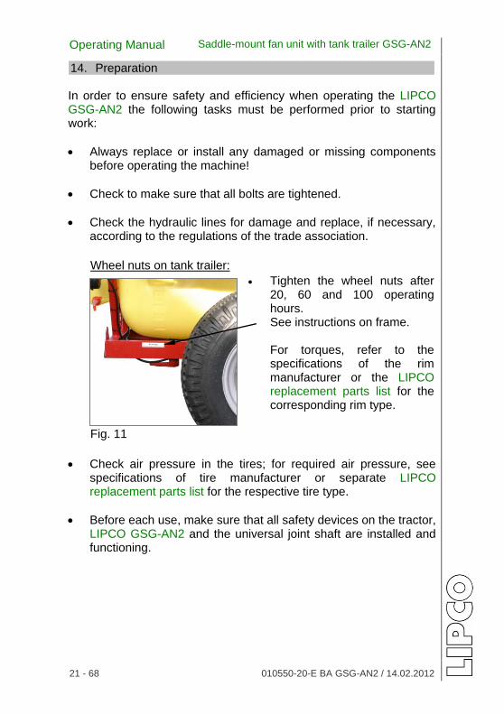
Wheel nuts on tank trailer:
Tighten the wheel nuts after 20, 60 and 100 operating hours. See instructions on frame.
For torques, refer to the specifications of the rim manufacturer or the LIPCO replacement parts list for the corresponding rim type.
Fig. 11
Check air pressure in the tires; for required air pressure, see specifications of tire manufacturer or separate LIPCO replacement parts list for the respective tire type.
Before each use, make sure that all safety devices on the tractor, LIPCO GSG-AN2 and the universal joint shaft are installed and functioning.

Operating Manual Saddle-mount fan unit with tank trailer GSG-AN2
22 - 68 010550-20-E BA GSG-AN2 / 14.02.2012
15. Attachment to the towing vehicle
Before operation, check the machine and the towing vehicle to ensure that they are safe for traffic and safe for operation!
No one may enter the area between the towing vehicle and the LIPCO GSG-AN2 unless the vehicle is secured against rolling by means of the parking brake and / or wheel chocks!
Do not enter the turning and swiveling area of the machine!
When the machine is in transport position, always make sure that the tractor’s lower links are sufficiently blocked from the side in order to prevent the machine from swinging out to the side!
The lower links must be secured so that they do not impact the tractor tires.
Upper/lower link:
The upper link can be used to align the erected tunnel parallel to the ground in the longitudinal direction of the vehicle. (Fig. 14)
Bolt for upper link Bolt for lower link Fig. 12
Connect the LIPCO GSG-AN2 to the respective points of the upper and lower links and secure.
Check the bolts of the upper and lower links on the LIPCO GSG-AN2 for damage and ensure that they are properly seated.

Operating Manual Saddle-mount fan unit with tank trailer GSG-AN2
23 - 68 010550-20-E BA GSG-AN2 / 14.02.2012
Bolt the control box, using the retaining bracket, to a suitable location on the tractor.
Control box:
Connect the control box to an existing 12-V socket on the tractor.
Control box:
Fig. 13
Figure 13 shows a fully electric control box in switched-off condition on the front of the LIPCO GSG-AN2; the mounting bracket for the control box is suspended in 2 hooks on the GSG frame.
For standard model without built-in hydraulics:
Connect hydraulic lines to the tractor, checking to make sure they are connected properly. Switch off the power take-off when connecting.
Hydraulic connection:
Connect hydraulic couplings for the adjustment of the tunnel width to the tractor. (Fig. 14)
Red = Fan unit 1 Blue = Fan unit 2
Fig. 14
Fig. 14 shows hydraulic hose couplings in the mounts provided for storage in the LIPCO GSG-AN2.

Operating Manual Saddle-mount fan unit with tank trailer GSG-AN2
24 - 68 010550-20-E BA GSG-AN2 / 14.02.2012
16. Attachment of the universal joint shaft
Prior to connecting or detaching the universal joint shaft, always make sure to switch off the power take-off shaft and motor and to remove the ignition key!
Press push pin and push the universal joint shaft onto the power take-off shaft until the pin locks into place! (Fig. 16)
Fig. 15 Fig. 16
After connecting the LIPCO GSG-AN2 to the tractor, check the length of the universal joint shaft.
Caution! Maximum overlapping is desirable. The universal joint shaft must not be pulled apart more than half of the overlap of the sliding profile. (See Fig. 15) When connecting to a different tractor, check the length again!
When the machine is not in use, the universal joint shaft can be inserted in the bracket provided for protection.
When connecting the universal joint shaft to the machine, make sure that the protective cover completely covers the universal joint shaft guard in all operating positions!
For your personal safety it is important that damaged or worn protective devices be replaced immediately.

Operating Manual Saddle-mount fan unit with tank trailer GSG-AN2
25 - 68 010550-20-E BA GSG-AN2 / 14.02.2012
Universal joint shaft guard: Secured safety chains prevent
the two-sided universal joint shaft guard from turning during operation. (Fig. 17)
Photo shows universal joint shaft with the lateral universal joint shaft shackles (e.g. for storage of the machine) Machine protective cover Fig. 17
During spraying the universal joint shaft must be able to turn freely and must not come into contact with the universal joints shaft storage bracket.
Connect safety chains for the universal joint shaft guard so that a sufficient swiveling area for the universal joint shaft is ensured in all operating positions. Do not use safety chains for suspending the universal joint shaft!

Operating Manual Saddle-mount fan unit with tank trailer GSG-AN2
26 - 68 010550-20-E BA GSG-AN2 / 14.02.2012
17. Attaching the LIPCO tank trailer
Trailer coupling
Coupling claw of the GSG-AN2 Coupling head of tank trailer. Hexagon bolt Crown nut Split pin
Fig. 18
Insert and secure the coupling head of the tank trailer in the coupling claw of the LIPCO GSG-AN2 before driving or working.
Insert the hexagon bolt from above and secure from below with a crown nut and a split pin.
Caution: Use a new split pin each time the trailer is attached.
Support wheel for tank trailers:
The support wheel (Fig. 19) is used only for parking of the tank trailer and must be moved to the uppermost position when driving or spraying, so that it does not come into contact with the ground.
Support wheel
Fig. 19

Operating Manual Saddle-mount fan unit with tank trailer GSG-AN2
27 - 68 010550-20-E BA GSG-AN2 / 14.02.2012
18. Driving on roads with the GSG-AN2
Special points to be observed when driving on roads!
Lights:
The lights of the tank trailer must be properly connected to the towing vehicle to ensure safe operation in traffic. (Fig. 20)
Connect lights
via the 7-pin 12V plug on the tractor.
Fig. 20
The fan units must be in the inner position, i.e. completely pushed together, and the hydraulic drive must be switched off.
To prevent the fan units from moving apart while driving, manual shut-off valves are built into the pressure lines of the hydraulic cylinder that is pressurized when extending the fan units. These valves must be closed when driving on roads.
Shut-off valve: The shut-off valves must
always be closed when driving on roads. (Fig. 21)
To spray at a later time, the valves must be opened again.
The shut-off valves are located in the pressure lines and are marked with a red cap.
Fig. 21
to tractor
open
Operating Manual Saddle-mount fan unit with tank trailer GSG-AN2
28 - 68 010550-20-E BA GSG-AN2 / 14.02.2012
19. Operating the LIPCO GSG-AN2
Caution: Do not use plant protection agents that tend to gum up or congeal – they have a negative effect on spraying.
19.1. Determining the amount of spray liquid needed The amount of spray liquid needed, which depends on the respective culture, the type of plant protection and the effectiveness of the plant protection agent, can be found in the instructions for the plant protection agent.
The working width (in meters) corresponds to the row width per tunnel.
The approximate driving speed (km/h) can be read from the speedometer of the towing vehicle.
In order to take into account any slippage in the drive wheels, this should be checked directly on the field. A driving speed of 5 to 7 km/h is recommended for spraying. 19.2. Checking the driving speed
Mark off a path with a length of 100 m.
Select a gear and engine speed to achieve the desired speed.
Drive the marked distance and record the time needed.
Calculate the driving speed or use the conversion table.
Adapt the RPM, if necessary, and repeat the procedure until the desired driving speed has been attained. Record the results in writing.

Operating Manual Saddle-mount fan unit with tank trailer GSG-AN2
29 - 68 010550-20-E BA GSG-AN2 / 14.02.2012
19.3. Calculation of the driving speed
The driving speed is calculated based on the following formula:
Driving speed (km/) =
Measured path (m) x 3.6 Time (sec.)
Sample calculation based on the following data: Measured path: 100 m Driving time: 60 sec. Calculation: 100 x 3.6
= 360
= 6 60 60
The driving speed is therefore 6 km/h.
Conversion of driving time to driving speed As an alternative to the above calculation, the approximate driving speed can be taken from the table below:
Driving speed (km/h)
Time for 100 m (sec.)
Driving speed (km/h)
Time for 100 m (sec.)
4.0 90.0 6.2 58.1
4.2 85.7 6.4 56.3
4.4 81.8 6.6 54.5
4.6 78.3 6.8 52.9
4.8 75.0 7.0 51.4
5.0 72.0 7.2 50.0
5.2 69.2 7.4 48.6
5.4 66.7 7.6 47.3
5.6 64.3 7.8 46.2
5.8 62.1 8.0 45.0
6.0 60.0

Operating Manual Saddle-mount fan unit with tank trailer GSG-AN2
30 - 68 010550-20-E BA GSG-AN2 / 14.02.2012
19.4. Nozzle selection and distribution quantity
The LIPCO GSG-AN2 is equipped with green ALBUZ AVI 80° flat fan venture nozzles. (Other nozzles are available on request.)
Fig. xx
During installation make sure that the seal is properly mounted before the fan nozzle.
Seal It is recommended that the nozzle body be swiveled upward for assembly in perpendicular position.
Determining the distribution quantity in l/min. from nozzle inserts in drip-stop nozzle bodies.
Distribution quantity of one nozzle
in l/m
Driving speed
Row spacing
Expended quantity
Number of Tunnel
=
(km/h) x (m) x l/ha x (units) 600 x Number of all open nozzles
The choice of required nozzles is based on the following nozzle charts. For the same nozzles, the discharge of liquid from the LIPCO GSG-AN2 corresponds to the product of the number of nozzles X single nozzle discharge.
ALBUZ AVI 80° flat fan venturi nozzle
(1 bar = 0.0689 lbf/in²)
bar 7 8 9 10 12 14 16 orange 0,61 0,65 0,69 0,73 0,80 0,86 0,92
grün 0,92 0,98 1,04 1,09 1,20 1,29 1,38
gelb 1,22 1,31 1,39 1,46 1,60 1,73 1,85
lila 1,53 1,63 1,73 1,82 2,00 2,16 2,31
If the unit is equipped with different nozzles, the discharge of all single nozzles must be added together. Please note that opposing nozzles must be identical.

Operating Manual Saddle-mount fan unit with tank trailer GSG-AN2
31 - 68 010550-20-E BA GSG-AN2 / 14.02.2012
19.5. Checking the liquid discharge General: The liquid discharge should generally be checked once each year at the start of the season and also in the event of changes in the liquid circulation or after replacing nozzles. Before determining the liquid discharge, the LIPCO GSG-AN2 must be equipped with the proper nozzles for the operating conditions. Use either the nozzle chart for the LIPCO GSG-AN2 or that of a nozzle manufacturer. Select nozzles based on the calculated driving speed and the desired distribution quantity so that the required nozzle discharge is distributed in the pressure range between 7 and 12 bar. The liquid discharge (l/min) now has to be checked at the unit.
Measurement:
Conduct the measurement using water only.
Fill the tank with water to a clearly visible mark. The marking should preferably be in the narrowest point in the filling mandrel, since the small diameter there immediately shows small changes in the liquid level.
This provides for a more accurate measurement and also reduces the time required for measuring.
After filling the tank with water, set the required pressure using the buttons on the control box with the spray nozzles switched on.
The pressure to be set is based on the calculated engine RPM for the optimum driving speed.
Make sure that all lines in the system are filled with liquid. Air in the system will result in an incorrect measurement.

Operating Manual Saddle-mount fan unit with tank trailer GSG-AN2
32 - 68 010550-20-E BA GSG-AN2 / 14.02.2012
If necessary, engage the sprayers until liquid is discharged evenly from the nozzles.
Switch off the LIPCO GSG-AN2 and again fill the tank to the selected marking on the filling mandrel.
Conduct a spray text for at least 2 min.
Determine the volume of liquid used by refilling to the marking and then compare with the calculated total discharge. (For smaller amounts or to increase the accuracy of the measurement, it may be necessary to spray for a longer duration.)
In case of deviations, correct the spray pressure and repeat the procedure. Higher pressure results in a greater discharge of liquid and vice versa.
Record the results in writing.

Operating Manual Saddle-mount fan unit with tank trailer GSG-AN2
33 - 68 010550-20-E BA GSG-AN2 / 14.02.2012
19.6. Nozzle adjustment during operation
Before blossoming: During / after blossoming / with full foliage:
Open only as many nozzles upward as required by the foliage wall.
90° position to foliage wall
Pressure 7-8 bar
Nozzles 80° fan jet or injector nozzles
Close upper nozzles depending on the foliage wall height.
Swivel nozzles 30° upward. (3rd position)
Pressure 12 - 15 bar
Nozzles 80° fan jet
Advantage of injector nozzles: Reduction of drift to rear

Operating Manual Saddle-mount fan unit with tank trailer GSG-AN2
34 - 68 010550-20-E BA GSG-AN2 / 14.02.2012
19.7. Spray nozzle adjustment
To switch off a nozzle, turn it either 90° downward or 90° upward. (Fig. 22)
Fig. 22
The nozzles used have the following positions:
-90 degrees / straight down Stop 0 degrees / horizontal for spraying before blossoming 15 degrees / upward not used 20 degrees / upward for spraying after blossoming 90 degrees / straight up Stop The correct setting of the nozzles is facilitated by a noticeable click when turning.
For all spraying, make sure that the center of the fan units is aligned to the center of the plants, so that the distances between the nozzles and the plants are the same.
For bud burst spraying, a narrow fan unit can be used, which has a positive effect on the return quantity.
The spray cones should overlap on the foliage wall in order to achieve optimum distribution. If the fan unit wall is too close to the foliage wall, the spray cones may no longer overlap and there will be areas in the foliage wall that receive no spray.

Operating Manual Saddle-mount fan unit with tank trailer GSG-AN2
35 - 68 010550-20-E BA GSG-AN2 / 14.02.2012
19.8. Recycling device
The recycling device enables the return of unused spray liquid.
To return the unused spray, the tunnel walls are provided with a collector at the bottom, with a built-in injector.
Recycling injector: The injector is covered with a
screen to prevent blockage. (Fig. 23)
The return line leads from the injector through the recycling filter to the spray tank.
The injectors are switched on and off via the control box.
Fig. 23
Recycling valve: The amount of surplus liquid
returned from the tunnel collector can be adjusted via the recycling valve on the main valve block. (Fig. 24) Recycling valve
Fig. 24
For spraying agents that tend to foam, it may be necessary to close the valve far enough to allow suction without the inclusion of excess air.
In the event of excessive foaming, the use of an anti-foaming agent in the spray liquid is recommended.

Operating Manual Saddle-mount fan unit with tank trailer GSG-AN2
36 - 68 010550-20-E BA GSG-AN2 / 14.02.2012
Commercially available anti-foaming agents can be used. Alternatively, it is also possible to add 0.02 l of rapeseed oil or salad oil for each 1000 l of spray liquid.
Important: After spraying, the recycling injector should remain in operation until the tunnel collector is completely empty.
Afterwards, switch off the recycling unit at the control box, and then switch off the universal joint shaft. This sequence prevents dripping of the spray liquid into the tunnel collector.
Control box:
The picture illustrates a control box. The switches can differ depending on the functions ordered. (Fig. 25)
The return line leads from the injector through the recycling filter to the spray tank.
The injectors are switched on and off via the control box. Fig. 25
Important: The recycling injectors operate at a minimum pressure of 5 bar.

Operating Manual Saddle-mount fan unit with tank trailer GSG-AN2
37 - 68 010550-20-E BA GSG-AN2 / 14.02.2012
20. Setting the LIPCO GSG-AN2
20.1. Calculation of the liquid discharge The liquid discharge is calculated based on the following formula:
Liquid
discharge in l/min
Driving speed
Row spacing
Expended quantity
Number of Tunnel
=
(km/h) x (m) x l/ha x
600
Sample calculation based on the following data: Required water quantity: 600 l/ha Driving speed 6 km/h Row spacing: 2 m Number of tunnels 2 Calculation: 600 x 6 x 2 x 2
= 24 l/min 600
The calculated liquid discharge for the entire LIPCO GSG-AN2 is therefore 24 l/min.
The required quantity of plant protection agent for the intended purpose is stated in the instructions for the plant protection agent.
The surface area is generally stated in hectares (ha).

Operating Manual Saddle-mount fan unit with tank trailer GSG-AN2
38 - 68 010550-20-E BA GSG-AN2 / 14.02.2012
20.2. Calculation of the required plant protection agent/spray
The required quantity of plant protection agent for the intended purpose is stated in the instructions for the plant protection agent.
The surface area is generally stated in hectares (ha).
The required quantity for the area to be treated can be calculated in 2 ways: Variant 1: Calculation of the required plant protection agent quantity in kg
Required quantity of agent (kg) = recommended quantity (kg/ha) x area
(ha)
Sample calculation based on the following data: Recommended quantity: 2 kg/ha Surface area to be treated: 70 a Area converted to ha 0.7 ha
Calculation:
2 x 0.7 = 1.4
The required quantity is 1.4 kg for 70 a
Variant 2: Calculation of the required quantity of water in l
Required water quantity (l) = recommended water quantity (kg/ha) x area
(ha)
Sample calculation based on the following data: Recommended water quantity: 400 l/ha Surface area to be treated: 70 a Area converted to ha 0.7 ha
Calculation: 400 x 0.7 = 280
The required water quantity is 280 l for 70 a

Operating Manual Saddle-mount fan unit with tank trailer GSG-AN2
39 - 68 010550-20-E BA GSG-AN2 / 14.02.2012
Caution: Never use more spray liquid than absolutely necessary. For the LIPCO GSG-AN2 the recycling rate should be included in the calculation. This is especially important for the last spraying. 20.3. Intervals for checking the dosing and distribution accuracy
of the LIPCO GSG-AN2
At least at the start of the spraying season the discharge quantity of the unit at the nozzles should be checked and compared with the data in the operating manual.
20.4. Which plant protection agents can be used in the LIPCO
GSG-AN2 ?
All plant protection agents approved by JKI BRAUNSCHWEIG are compatible, but should not be left in the tank longer than necessary.

Operating Manual Saddle-mount fan unit with tank trailer GSG-AN2
40 - 68 010550-20-E BA GSG-AN2 / 14.02.2012
21. Conducting test spraying Fill GSG-AN2 spray liquid tank partially with water, not
pressurized.
Set the 3-way valve (Fig. 26) to the “Suction tank” position. The 3-way valve of the LIPCO tank trailer is located under the spray liquid tank.
Fig. 26
Position: “Suction tank” Liquid is pumped from the spray liquid tank / fresh water tank to the nozzles in the tunnel walls.
Switch on mixing unit and recycling injectors.
Open required nozzles.
Switch on power take-off shaft for pump and regulate to max. 540 RPM.
Set the desired pressure at the control box and check whether nozzles are spraying correctly.
Conduct test spraying with water for nozzle setting on foliage wall.

Operating Manual Saddle-mount fan unit with tank trailer GSG-AN2
41 - 68 010550-20-E BA GSG-AN2 / 14.02.2012
22. Preparation of spraying liquid
Prepare only the quantity of plant protection agent needed.
Fill approximately 75% of the calculated water quantity in the spray liquid tank.
When filling with water from the drinking water supply, do not immerse water hose in the spray liquid.
Surface water may be used only after obtaining official permission and if measures are taken to prevent contamination.
The spraying liquid tank can also be filled via an optionally available external suction unit.
The spray liquid tank is equipped with a hydraulic mixing unit to keep the spraying liquid in motion and prevent settling.
Hydraulic mixing unit:
Fig. 27 Shut-off valve Fig. 28 33
The mixing unit is switched on and off via the shut-off valve.
Then fill the plant protection agent in the filling strainer and flush in via the flushing mechanism.
Operating Manual Saddle-mount fan unit with tank trailer GSG-AN2
42 - 68 010550-20-E BA GSG-AN2 / 14.02.2012
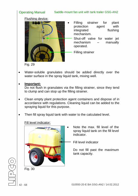
Flushing device:
Filling strainer for plant protection agent with integrated flushing mechanism.
Shut-off valve for water jet mechanism – manually operated.
Filling strainer
Fig. 29
Water-soluble granulates should be added directly over the water surface in the spray liquid tank, mixing well.
Important: Do not flush in granulates via the filling strainer, since they tend to clump and can stop up the filling strainer.
Clean empty plant protection agent containers and dispose of in accordance with regulations. Cleaning liquid can be added to the spraying liquid for this purpose.
Then fill spray liquid tank with water to the calculated level. Fill level indicator:
Note the max. fill level of the spray liquid tank on the fill level indicator. Fill level indicator Do not fill past the maximum tank capacity.
Fig. 30
Operating Manual Saddle-mount fan unit with tank trailer GSG-AN2
43 - 68 010550-20-E BA GSG-AN2 / 14.02.2012
23. Emptying the GSG-AN2 after use Plant protection agents are only allowed to be used on agricultural / forested / horticultural surfaces. This applies also to the remaining agent, which remains for technical reasons in the tank and for the liquid, which cumulates during inner and outer cleaning of the machine after use. Plant protection agents should never remain in the LIPCO GSG-AN2 for an extended period; therefore, the precise amount of spraying liquid needed should be calculated before spraying. Remaining spraying liquid must be disposed according the regulations of JKI Braunschweig. When diluting with fresh water it is a good idea to add the water via the tank cleaning nozzle. This allows the tank to be cleaned while diluting the agent. It is advisable to switch off the mixing unit for the last 50 l, in order to empty the tank as far as possible.

Operating Manual Saddle-mount fan unit with tank trailer GSG-AN2
44 - 68 010550-20-E BA GSG-AN2 / 14.02.2012
24. Residual volume
For technical reasons, a certain volume of liquid will always remain in the tank. It cannot be removed by means of the pump and nozzle. The below indicated remaining volume applies up to an inclination of 8%, higher inclination will create higher residual volume.
Remaining residual volume up to 8% inclination:
GSG-AN2 25 l.
The residual volume cannot be removed by means of the pump and nozzle. 25. Interruption of spraying process
If the spraying process will be interrupted e.g. due to weather reasons, all parts which were in contact with spraying agent like pump, spraying pipes, fittings and filters should be cleaned on the spraying ground. Normally a length of the run of 20 m is sufficient. This cleaning avoids blockage of filters and nozzles.
Abb. 30a Abb. 30b
Set the 3-way valve to the middle position “Clean suction filter” (Fig. 30a). This will shut-off the agent spraying circuit.
1
2

Operating Manual Saddle-mount fan unit with tank trailer GSG-AN2
45 - 68 010550-20-E BA GSG-AN2 / 14.02.2012
Set both 2-way valves to position “Machine cleaning” (Fig. 30b). The pump will bring fresh water from fresh water tank to the spraying nozzles.
Shut-off Recycling procedure on control box.
This will avoid, that cleaning liquid will be pumped through recycling injectors back to the spray liquid tank, thus thinning the liquid in the spray liquid tank.
Switch on pump, water from fresh water tank is now cleaning all fittings, filters close to the spraying nozzles and the nozzles themselves.
The cleaning liquid must be disposed on agricultural / forested /
horticultural surface.

Operating Manual Saddle-mount fan unit with tank trailer GSG-AN2
46 - 68 010550-20-E BA GSG-AN2 / 14.02.2012
26. Cleaning of the GSG-AN2 after use
The cleaning of the machine should be done on an untreated surface on the field. Cleaning should be done with a spraying gun, which is supplied by water out of the fresh water tank.
After use, the LIPCO GSG-AN2 must be cleaned thoroughly inside and outside using plenty of water; sodium carbonate can be added for better results.
For the cleaning process itself, move the fan units to the closest position and switch on the pump, nozzles and suction unit.
To clean the pump, fittings and hoses, fill the fresh water tank with water and operate the pump for a short period. All fittings should be actuated several times in order to ensure thorough cleaning.
Take special care in cleaning nozzles and filters; it may even be necessary to dismantle these parts to check for wear or damage. Replace worn or damaged parts.
Caution: When spraying the outside of the LIPCO GSG-AN2 with water, please note that the control box is only protected against splashing water; never subject it to direct water spray or weather. When spraying the machine, also retract all hydraulic cylinders in order to prevent corrosion on the piston rods.
Caution: To clean the various filters, first de-pressurize the liquid circuit.

Operating Manual Saddle-mount fan unit with tank trailer GSG-AN2
47 - 68 010550-20-E BA GSG-AN2 / 14.02.2012
Cleaning the suction filter:
To clean the suction filter, set the 3-way valve to the middle position “Clean suction filter” (Fig. 31)
This shuts off the supply of spray liquid to the suction filter and the filter cartridge can now be screwed off for cleaning.
Fig. 31
Cleaning the inside of the liquid spray tank:
The spray liquid tank is equipped with a rotating nozzle for cleaning the inside of the tank. (Fig. 32)
The nozzle is supplied with fresh water from the fresh water tank. It is switched on while the pump is running via the supply valve on the top of the spray liquid tank.
Fig. 32
Cleaning the recycling circuit:
To clean the recycling circuit, set the 2-way valve to the “Clean machine” setting. (Fig. 33)
The fresh water now circulates from the fresh water tank the spray liquid container via the recycling circuit.
Fig. 33
Operating Manual Saddle-mount fan unit with tank trailer GSG-AN2
48 - 68 010550-20-E BA GSG-AN2 / 14.02.2012
Excess spraying liquid must be disposed of in accordance with applicable JKI Braunschweig regulations.
If the LIPCO GSG-AN2 is not to be used for an extended period, oil the metal parts that are subject to corrosion. The upper telescoping tube for the tunnel width adjustment should be lubricated using a-long-lasting grease with high adhesive strength.

Operating Manual Saddle-mount fan unit with tank trailer GSG-AN2
49 - 68 010550-20-E BA GSG-AN2 / 14.02.2012
27. Maintenance
Caution: Always secure the tunnel spray unit from rolling or tipping during maintenance and repair work.
Measures for keeping the machine in optimum operating condition:
Fan unit wall:
The fan unit wall has a double-wall construction for production reasons. If liquid collects in the hollow space in the fan unit wall, it can be drained via the drain plug at the bottom. This is especially important in the event of sub-freezing temperatures.
Fig. 34
Lubrication point for telescopic guides:
Lubricate the telescopic guides on the fan unit walls using long-lasting grease and then completely extend and retract the fan unit walls one time to distribute the grease evenly on the guide tubes. (Fig. 35)
Grease here on both sides
Fig. 35

Operating Manual Saddle-mount fan unit with tank trailer GSG-AN2
50 - 68 010550-20-E BA GSG-AN2 / 14.02.2012
Lubrication points:
Lubricate at grease nipple on drawbar every 6 months.
Grease nipple (2x)
Fig. 36
Pump:
Pump oil tank
Check pump oil level. Check oil in inspection glass regularly; in case of discoloration, check membranes!
Fig. 37
First oil change of approx. 50 hours of operation, or at the end of the season.
Further oil changes after every 500 hours of operation, or at the end of the season.
Use SAE 20W 40 oil: quantity = 1.35 l
Check the membranes annually for damage; if they need to be replaced, use only LIPCO original replacement parts.

Operating Manual Saddle-mount fan unit with tank trailer GSG-AN2
51 - 68 010550-20-E BA GSG-AN2 / 14.02.2012
Air receiver:
Valve for pressure check of air receiver.
Set the pressure of the air receiver to approx. 20% of the spraying pressure and check occasionally.
Fig. 38 Pump pressure control valve:
Safety button
If the pump safety control valve is activated for any reason, then push the safety button in all the way after eliminating the cause.
Fig. 39
Check all hydraulic connections, chains, springs and spray hose connections regularly to ensure that they are tight.
Before opening or releasing pressurized parts (valves, hoses, etc.), they must be de-pressurized.
Caution: Nozzles and other small parts that come into contact with the spray liquid should never be blown out with the mouth.
After working on pressurized parts, always check the seals in the pressure circuit before operating the system with plant protection agents.
Clean all filters.
Operating Manual Saddle-mount fan unit with tank trailer GSG-AN2
52 - 68 010550-20-E BA GSG-AN2 / 14.02.2012
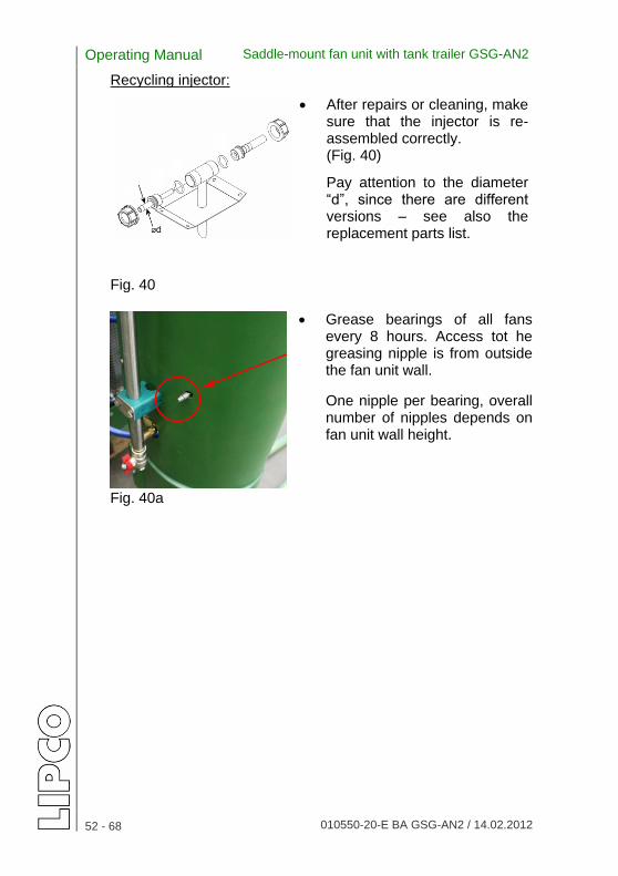
Recycling injector:
After repairs or cleaning, make sure that the injector is re-assembled correctly. (Fig. 40)
Pay attention to the diameter “d”, since there are different versions – see also the replacement parts list.
Fig. 40
Grease bearings of all fans every 8 hours. Access tot he greasing nipple is from outside the fan unit wall.
One nipple per bearing, overall number of nipples depends on fan unit wall height.
Fig. 40a

Operating Manual Saddle-mount fan unit with tank trailer GSG-AN2
53 - 68 010550-20-E BA GSG-AN2 / 14.02.2012
28. Machine inspection
28.1. Pressure check
A pressure check may become necessary during a machine inspection.
Please observe the following:
Test connection for pressure check: To check the system pressure
(e.g. during inspection of the machine), a test manometer can be screwed onto the ¼” test connection of the pressure control valve.
(Fig. 41)
When not in use, the test ¼” connection is closed by a plug and seal. Fig. 41
Pressure control valve 28.2. Flow rate check A flow rate check may become necessary during a machine inspection. For checking, an adapter 1” must be build in between pump and pressure hose. Flow rate checking unit must be adapted to this 1” adapter. (see also functional diagram) After completion of the test, the fittings must be restored to their original state, ensuring that there are no leaks.

Operating Manual Saddle-mount fan unit with tank trailer GSG-AN2
54 - 68 010550-20-E BA GSG-AN2 / 14.02.2012
29. Troubleshooting
The following table should help you to quickly locate and eliminate any malfunctions.
Location of fault Possible cause Solution Incorrect suction of excess spray liquid
Recycling filter blocked
Clean recycling filter
Injector nozzle blocked
Clean injector nozzle
Injector nozzle not aligned with suction nozzle
Re-align injector nozzle
Return hose squeezed or blocked at input to recycling filter
Eliminate squeezing / blockage
Recycling circuit shut off Switch on recycling at control box Adjust recycling valve
Insufficient pump capacity
Suction filter blocked
Clean suction filter
Insufficient pressure in air receiver
Check pressure in air receiver via test valve
Leak in suction line
Seal suction line
Insufficient RPM Set specified RPM - max. 540 rpm
Pump membrane defective: discernible by opaque lubricating oil
Replace membrane
Air receiver membrane defective: discernible by irregular display on manometer in control box
Replace membrane
Pressure control valve on pump activated
Adjust pressure control valve downward + push in brass pin on PCV until it locks into place
Operating Manual Saddle-mount fan unit with tank trailer GSG-AN2
55 - 68 010550-20-E BA GSG-AN2 / 14.02.2012
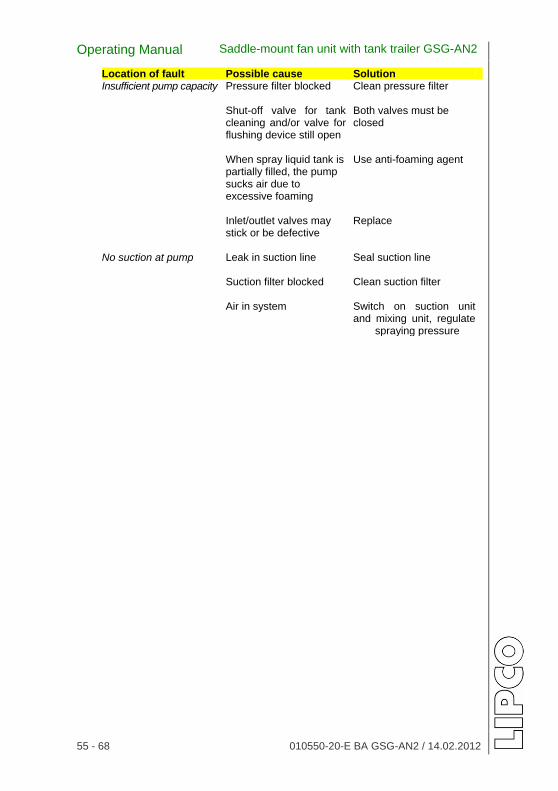
Location of fault Possible cause Solution Insufficient pump capacity Pressure filter blocked Clean pressure filter
Shut-off valve for tank
cleaning and/or valve for flushing device still open
Both valves must be closed
When spray liquid tank is partially filled, the pump sucks air due to excessive foaming
Use anti-foaming agent
Inlet/outlet valves may stick or be defective
Replace
No suction at pump Leak in suction line
Seal suction line
Suction filter blocked
Clean suction filter
Air in system Switch on suction unit and mixing unit, regulate spraying pressure

Operating Manual Saddle-mount fan unit with tank trailer GSG-AN2
56 - 68 010550-20-E BA GSG-AN2 / 14.02.2012
30. Storing the machine In case the LIPCO GSG-AN2 is not used for an extended period, you should perform the following steps:
Check the function of all moving parts and replace worn or damaged parts.
Check valves and fittings.
Check to make sure that all bolts are tightened.
Check oil and grease levels.
Empty all tanks via the valves/drain plugs and clean using fresh water.
Do not tightly close tanks during storage to prevent mold.
Store unused spray liquid in the containers provided until next use.
Clean suction filter using fresh water.
To protect the tunnel spray unit from damage during the winter months, the unit must be filled with an antifreeze agent mixed with water after cleaning all parts. (The proportion of anti-freeze agent to water is based on the expected temperatures.)
Afterwards, rinse all elements of the liquid circulation by means of the pump; actuate all valves / shut-off gates and nozzles several times to ensure that all parts come into contact with the anti-freeze solution, so they are coated with a protective film.
The anti-freeze solution should remain in the spray unit throughout the winter; do not drain until there is no longer a danger of frost in the spring.

Operating Manual Saddle-mount fan unit with tank trailer GSG-AN2
57 - 68 010550-20-E BA GSG-AN2 / 14.02.2012
The anti-freeze agent prevents corrosion on the pump parts and aging of seals.
The anti-freeze can be re-used the following winter.
Remove nozzles, clean (e.g. with a soft brush – do not use hard objects!) and store in a protected place.
Remove filters, clean and check for damage.
Check oil level of pump, check membranes and valves for damage.
Replace damaged parts only with LIPCO original replacement parts.
Grease all unpainted parts to protect them from corrosion, then cover the LIPCO GSG-AN2 and store in a dry, frost-free room to keep the unit ready for use.
Caution! Follow the instructions in Chapter 27, “Maintenance” before operating the unit again.

Operating Manual Saddle-mount fan unit with tank trailer GSG-AN2
58 - 68 010550-20-E BA GSG-AN2 / 14.02.2012
31. Warranty We guarantee products from our production against defects in craftsmanship and assembly. The warranty is limited to replacement of the parts determined to be defective. The duration of the warranty is in accordance with the applicable laws at the time the machine is delivered to the customer. Repairs during the warranty period must be coordinated with the manufacturer. We expressly state that warranty claims can be asserted only after examination and/or return of the defective parts.
The returned parts must be accompanied by the completed warranty application. The warranty will be voided:
if the user modifies the original construction of the machine,
if parts other than original replacement parts from LIPCO are used,
in the event of incorrect operation,
if the maximum power is exceeded,
in the event that the machine is used improperly,
in the event of failure to comply with this operating manual Labels Each machine bears a rating plate with the following data:
Manufacturer
Year of manufacture
Machine no.
Model designation Always include this data when ordering replacement parts or for servicing.

Operating Manual Saddle-mount fan unit with tank trailer GSG-AN2
59 - 68 010550-20-E BA GSG-AN2 / 14.02.2012
32. Functional diagram GSG AN2
1. Pressure filter 14. 2-way valve 2. Electric valves (spray liquid/fresh water) 3. Pressure control valve 15. Suction filter
4. Electric control box 16. 3-way valve (drain valve/suction filter)
5. Safety pressure control valve 17. Hand washing water 6. Fan unit 18. 2-way valve (recycling nozzle) 7. Recycling filter (1 per fan unit) 19. Container cleaning nozzle 8. Fresh water tank (for cleaning machine) 20. Quick cleaning of pressure filter and 9. Tank connection for external 10. Flushing device cleaning 11. Mixing unit 21. 2-way valve (container cleaning) 12. 2-way valve (flushing device) 22. Pressure filter for nozzle 13. Pump 23. Site for flow check 24. 2-way valve (cleaning)

Operating Manual Saddle-mount fan unit with tank trailer GSG-AN2
60 - 68 010550-20-E BA GSG-AN2 / 14.02.2012
33. Electric diagram for GSG-AN2
Wiring diagram shows maximum possible design. Deviations in actual machine delivered are possible!!

Operating Manual Saddle-mount fan unit with tank trailer GSG-AN2
61 - 68 010550-20-E BA GSG-AN2 / 14.02.2012
34. Hydraulic diagram for GSG-AN2
The above hydraulic diagram for the two-row LIPCO TSG-AN also applies to the single-row model.

Operating Manual Saddle-mount fan unit with tank trailer GSG-AN2
62 - 68 010550-20-E BA GSG-AN2 / 14.02.2012
35. Combination matrix for GSG-AN2
Operating Manual Saddle-mount fan unit with tank trailer GSG-AN2
63 - 68 010550-20-E BA GSG-AN2 / 14.02.2012
36. Notes ……………………………………………………………………………….. ……………………………………………………………………………..………………………………………………………………………………….. ……………………………………………………………………………..…………………………………………………………………………………..……………………………………………………………………………..…………………………………………………………………………………..……………………………………………………………………………..………………………………………………………………………………….. ……………………………………………………………………………….. ……………………………………………………………………………..………………………………………………………………………………….. ……………………………………………………………………………..…………………………………………………………………………………..……………………………………………………………………………..…………………………………………………………………………………..……………………………………………………………………………..………………………………………………………………………………….. ……………………………………………………………………………….. ……………………………………………………………………………..………………………………………………………………………………….. ……………………………………………………………………………..…………………………………………………………………………………..……………………………………………………………………………..…………………………………………………………………………………..……………………………………………………………………………..………………………………………………………………………………….. ……………………………………………………………………………….. ……………………………………………………………………………..………………………………………………………………………………….. ……………………………………………………………………………..…………………………………………………………………………………..……………………………………………………………………………..…………………………………………………………………………………..……………………………………………………………………………..………………………………………………………………………………….. ……………………………………………………………………………….. ……………………………………………………………………………..………………………………………………………………………………….. ……………………………………………………………………………..…………………………………………………………………………………..

Operating Manual Saddle-mount fan unit with tank trailer GSG-AN2
64 - 68 010550-20-E BA GSG-AN2 / 14.02.2012
……………………………………………………………………………….. ……………………………………………………………………………..………………………………………………………………………………….. ……………………………………………………………………………..…………………………………………………………………………………..……………………………………………………………………………..…………………………………………………………………………………..……………………………………………………………………………..………………………………………………………………………………….. ……………………………………………………………………………….. ……………………………………………………………………………..………………………………………………………………………………….. ……………………………………………………………………………..…………………………………………………………………………………..……………………………………………………………………………..…………………………………………………………………………………..……………………………………………………………………………..………………………………………………………………………………….. ……………………………………………………………………………….. ……………………………………………………………………………..………………………………………………………………………………….. ……………………………………………………………………………..…………………………………………………………………………………..……………………………………………………………………………..…………………………………………………………………………………..……………………………………………………………………………..………………………………………………………………………………….. ……………………………………………………………………………….. ……………………………………………………………………………..………………………………………………………………………………….. ……………………………………………………………………………..…………………………………………………………………………………..……………………………………………………………………………..…………………………………………………………………………………..……………………………………………………………………………..………………………………………………………………………………….. ……………………………………………………………………………….. ……………………………………………………………………………..………………………………………………………………………………….. ……………………………………………………………………………..…………………………………………………………………………………..……………………………………………………………………………..…………………………………………………………………………………..

Operating Manual Saddle-mount fan unit with tank trailer GSG-AN2
65 - 68 010550-20-E BA GSG-AN2 / 14.02.2012
……………………………………………………………………………….. ……………………………………………………………………………..………………………………………………………………………………….. ……………………………………………………………………………..…………………………………………………………………………………..……………………………………………………………………………..…………………………………………………………………………………..……………………………………………………………………………..………………………………………………………………………………….. ……………………………………………………………………………….. ……………………………………………………………………………..………………………………………………………………………………….. ……………………………………………………………………………..…………………………………………………………………………………..……………………………………………………………………………..…………………………………………………………………………………..……………………………………………………………………………..………………………………………………………………………………….. ……………………………………………………………………………….. ……………………………………………………………………………..………………………………………………………………………………….. ……………………………………………………………………………..…………………………………………………………………………………..……………………………………………………………………………..…………………………………………………………………………………..……………………………………………………………………………..………………………………………………………………………………….. ……………………………………………………………………………….. ……………………………………………………………………………..………………………………………………………………………………….. ……………………………………………………………………………..…………………………………………………………………………………..……………………………………………………………………………..…………………………………………………………………………………..……………………………………………………………………………..………………………………………………………………………………….. ……………………………………………………………………………..………………………………………………………………………………….. ……………………………………………………………………………….. ……………………………………………………………………………..………………………………………………………………………………….. ……………………………………………………………………………..… ……………………………………………………………………………..…

Operating Manual Saddle-mount fan unit with tank trailer GSG-AN2
66 - 68 010550-20-E BA GSG-AN2 / 14.02.2012
……………………………………………………………………………..………………………………………………………………………………….. ……………………………………………………………………………..…………………………………………………………………………………..……………………………………………………………………………..…………………………………………………………………………………..……………………………………………………………………………..………………………………………………………………………………….. ……………………………………………………………………………….. ……………………………………………………………………………..………………………………………………………………………………….. ……………………………………………………………………………..…………………………………………………………………………………..……………………………………………………………………………..…………………………………………………………………………………..……………………………………………………………………………..………………………………………………………………………………….. ……………………………………………………………………………….. ……………………………………………………………………………..………………………………………………………………………………….. ……………………………………………………………………………..…………………………………………………………………………………..……………………………………………………………………………..…………………………………………………………………………………..……………………………………………………………………………..………………………………………………………………………………….. ……………………………………………………………………………….. ……………………………………………………………………………..………………………………………………………………………………….. ……………………………………………………………………………..…………………………………………………………………………………..……………………………………………………………………………..…………………………………………………………………………………..……………………………………………………………………………..………………………………………………………………………………….. ……………………………………………………………………………….. ……………………………………………………………………………..… ………………………………………………………………………………..……………………………………………………………………………..…………………………………………………………………………………..……………………………………………………………………………..………………………………………………………………………………….. ………………………………………………………………………………..

Operating Manual Saddle-mount fan unit with tank trailer GSG-AN2
67 - 68 010550-20-E BA GSG-AN2 / 14.02.2012
37. EG Declaration of conformity Manufacturer: person authorized to compile the
technical files: LIPCO GmbH Günther Bauer Am Fuchsgraben 5b Ingenieurbüro Bauer D-77880 Sasbach Rieselfeldallee 39a Tel. +49 (0) 7841 6068-0 D-79111 Freiburg Fax +49 (0) 7841 6068-10 Tel. +49 (0) 172 7694 903 E-Mail [email protected] Fax +49 (0) 761 5565 576 Internet http://www.lipco.com E-Mail [email protected]
Denomination: LIPCO Saddle-mount fan unit with tank trailer
GSG-AN2
Serial no:
Year of manufacture:
The manufacturer declares expressly, that the machinery fulfills all the relevant provisions of the
Directive 2006/42/EC To implement the safety and health requirements as stated in the CE Directive, the following standard(s) and/or technical specification(s) has (have) been applied:
EN ISO 4254-1, 06/06
EN ISO 12100-1 / EN ISO 12100-2
EN ISO 14121-1
DIN EN 907, 07/97 This declaration of conformity loses its validity, if changes or modifications on the machine were made, which are not approved in writing before by LIPCO. Marietta Panter - Managing partner -
Sasbach, 14.02.2012
(Place and date of issuing) (Name, function and signature of responsible)

Design: [email protected]


![MU AN2 [Recovered]](https://img.dokumen.tips/doc/110x75/55cf85cf550346484b919363/mu-an2-recovered.jpg)