Embed Size (px)
Citation preview

OO Analysis and Designwith UML and USDP
Workbook
Created by Dr. Jim Arlow
Version 2.0
UML Course Student Workbook 2.0 © 2004 Clear View Training Limited
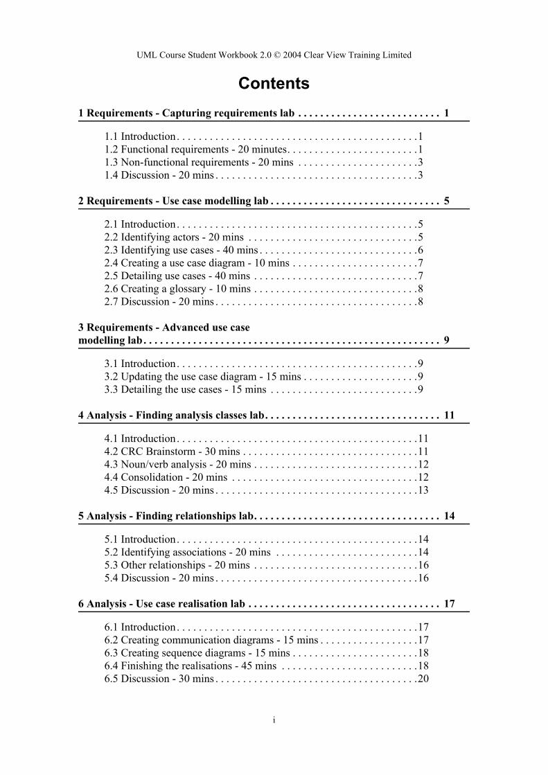
Contents1 Requirements - Capturing requirements lab . . . . . . . . . . . . . . . . . . . . . . . . . . 1
1.1 Introduction. . . . . . . . . . . . . . . . . . . . . . . . . . . . . . . . . . . . . . . . . . . .11.2 Functional requirements - 20 minutes. . . . . . . . . . . . . . . . . . . . . . . .11.3 Non-functional requirements - 20 mins . . . . . . . . . . . . . . . . . . . . . .31.4 Discussion - 20 mins . . . . . . . . . . . . . . . . . . . . . . . . . . . . . . . . . . . . .3
2 Requirements - Use case modelling lab . . . . . . . . . . . . . . . . . . . . . . . . . . . . . . . 5
2.1 Introduction. . . . . . . . . . . . . . . . . . . . . . . . . . . . . . . . . . . . . . . . . . . .52.2 Identifying actors - 20 mins . . . . . . . . . . . . . . . . . . . . . . . . . . . . . . .52.3 Identifying use cases - 40 mins . . . . . . . . . . . . . . . . . . . . . . . . . . . . .62.4 Creating a use case diagram - 10 mins . . . . . . . . . . . . . . . . . . . . . . .72.5 Detailing use cases - 40 mins . . . . . . . . . . . . . . . . . . . . . . . . . . . . . .72.6 Creating a glossary - 10 mins . . . . . . . . . . . . . . . . . . . . . . . . . . . . . .82.7 Discussion - 20 mins . . . . . . . . . . . . . . . . . . . . . . . . . . . . . . . . . . . . .8
3 Requirements - Advanced use case modelling lab. . . . . . . . . . . . . . . . . . . . . . . . . . . . . . . . . . . . . . . . . . . . . . . . . . . . . . 9
3.1 Introduction. . . . . . . . . . . . . . . . . . . . . . . . . . . . . . . . . . . . . . . . . . . .93.2 Updating the use case diagram - 15 mins . . . . . . . . . . . . . . . . . . . . .93.3 Detailing the use cases - 15 mins . . . . . . . . . . . . . . . . . . . . . . . . . . .9
4 Analysis - Finding analysis classes lab. . . . . . . . . . . . . . . . . . . . . . . . . . . . . . . . 11
4.1 Introduction. . . . . . . . . . . . . . . . . . . . . . . . . . . . . . . . . . . . . . . . . . . .114.2 CRC Brainstorm - 30 mins . . . . . . . . . . . . . . . . . . . . . . . . . . . . . . . .114.3 Noun/verb analysis - 20 mins . . . . . . . . . . . . . . . . . . . . . . . . . . . . . .124.4 Consolidation - 20 mins . . . . . . . . . . . . . . . . . . . . . . . . . . . . . . . . . .124.5 Discussion - 20 mins . . . . . . . . . . . . . . . . . . . . . . . . . . . . . . . . . . . . .13
5 Analysis - Finding relationships lab. . . . . . . . . . . . . . . . . . . . . . . . . . . . . . . . . . 14
5.1 Introduction. . . . . . . . . . . . . . . . . . . . . . . . . . . . . . . . . . . . . . . . . . . .145.2 Identifying associations - 20 mins . . . . . . . . . . . . . . . . . . . . . . . . . .145.3 Other relationships - 20 mins . . . . . . . . . . . . . . . . . . . . . . . . . . . . . .165.4 Discussion - 20 mins . . . . . . . . . . . . . . . . . . . . . . . . . . . . . . . . . . . . .16
6 Analysis - Use case realisation lab . . . . . . . . . . . . . . . . . . . . . . . . . . . . . . . . . . . 17
6.1 Introduction. . . . . . . . . . . . . . . . . . . . . . . . . . . . . . . . . . . . . . . . . . . .176.2 Creating communication diagrams - 15 mins . . . . . . . . . . . . . . . . . .176.3 Creating sequence diagrams - 15 mins . . . . . . . . . . . . . . . . . . . . . . .186.4 Finishing the realisations - 45 mins . . . . . . . . . . . . . . . . . . . . . . . . .186.5 Discussion - 30 mins . . . . . . . . . . . . . . . . . . . . . . . . . . . . . . . . . . . . .20
i

UML Course Student Workbook 2.0 © 2004 Clear View Training Limited
7 Design - The design model lab . . . . . . . . . . . . . . . . . . . . . . . . . . . . . . . . . . . . . . 21
7.1 Introduction. . . . . . . . . . . . . . . . . . . . . . . . . . . . . . . . . . . . . . . . . . . .217.2 Scope of the vertical slice . . . . . . . . . . . . . . . . . . . . . . . . . . . . . . . . .217.3 Subsystems and layers - 5 mins . . . . . . . . . . . . . . . . . . . . . . . . . . . .227.4 Creating the design classes - 30 mins . . . . . . . . . . . . . . . . . . . . . . . .227.5 Sequence diagram - 15 mins . . . . . . . . . . . . . . . . . . . . . . . . . . . . . . .24
8 Design - state machines lab. . . . . . . . . . . . . . . . . . . . . . . . . . . . . . . . . . . . . . . . . 26
8.1 Introduction. . . . . . . . . . . . . . . . . . . . . . . . . . . . . . . . . . . . . . . . . . . .268.2 Order processing - 30 mins . . . . . . . . . . . . . . . . . . . . . . . . . . . . . . . .268.3 Adding and removing items from an order - 30 mins. . . . . . . . . . . .26
9 Deployment and implementation lab . . . . . . . . . . . . . . . . . . . . . . . . . . . . . . . . . . . . . . . . . . . . . 28
9.1 Introduction - ECP deployment . . . . . . . . . . . . . . . . . . . . . . . . . . . .289.2 Nodes - 15 mins . . . . . . . . . . . . . . . . . . . . . . . . . . . . . . . . . . . . . . . .289.3 Components - 15 mins . . . . . . . . . . . . . . . . . . . . . . . . . . . . . . . . . . .29
Appendix 1 ECP Informal System Specification. . . . . . . . . . . . . . . . . . . . . . . . . 30
A1.1 Introduction . . . . . . . . . . . . . . . . . . . . . . . . . . . . . . . . . . . . . . . . . .30A1.2 The specification document . . . . . . . . . . . . . . . . . . . . . . . . . . . . . .30
Appendix 2 ECP User Interface Prototype . . . . . . . . . . . . . . . . . . . . . . . . . . . . . 33
A2.1 Introduction . . . . . . . . . . . . . . . . . . . . . . . . . . . . . . . . . . . . . . . . . .33A2.2 Clear View Training Home Page . . . . . . . . . . . . . . . . . . . . . . . . . .33A2.3 Books . . . . . . . . . . . . . . . . . . . . . . . . . . . . . . . . . . . . . . . . . . . . . . .34A2.4 Computers Category. . . . . . . . . . . . . . . . . . . . . . . . . . . . . . . . . . . .35A2.5 Your Selection . . . . . . . . . . . . . . . . . . . . . . . . . . . . . . . . . . . . . . . .36A2.6 Your Basket . . . . . . . . . . . . . . . . . . . . . . . . . . . . . . . . . . . . . . . . . .37A2.7 Here is your order. . . . . . . . . . . . . . . . . . . . . . . . . . . . . . . . . . . . . .38
Appendix 3 ECP Outline Technical Architecture . . . . . . . . . . . . . . . . . . . . . . . . 39
A3.1 Introduction . . . . . . . . . . . . . . . . . . . . . . . . . . . . . . . . . . . . . . . . . .39
ii
UML Course Student Workbook 2.0 © 2004 Clear View Training Limited
1 Requirements - Capturing requirements lab
1.1 IntroductionIn order to successfully complete the Capturing Requirements Lab you will need the fol-lowing documentation:
• E-Commerce Platform Informal System Specification (in Appendix 1)• E-Commerce Platform User Interface Prototype (in Appendix 2)
You will also need to interview the lecturer, as not all of the functional and non-functional requirements for the system may be apparent from these documents. They do, however, provide a baseline set of information that you can use to design the system.
1.2 Functional requirements - 20 minutes
1.2.1 Procedure
Take the existing project documentation (listed in the Introduction) and extract a set of functional requirements. These functional requirements must be expressed as a set of de-clarative “shall” statements, as described in the course notes (see Requirements).
You will need to interview the lecturer to find out additional information about the system that is not included in the existing documents. You can delegate one member of your team to ask questions, or take turns. Either way, you should all come along to watch the inter-view process.
When you approach the lecturer you should have a list of questions already prepared. Your questions should be:
• Specific• Concise• Answerable
As the interview continues, you may formulate and ask more questions. This is OK.
The interview is limited to 5 minutes - so you will have to be very focused.
Your team will produce a Software Requirements Specification that captures the function-al requirements of the ECP as a set of “shall” statements.
The list of functional requirements shall be divided into sections that group related re-quirements into cohesive sets. These sections might include “User Interface”, “Payment”, “Orders” etc.
Each requirement shall be given a unique ID number for traceability.
1

UML Course Student Workbook 2.0 © 2004 Clear View Training Limited
Each functional requirement shall be assigned a priority M, S, C or W according to the MoSCoW criteria listed in Table 1:
1.2.2 Deliverables
1.3 Non-functional requirements - 20 mins
1.3.1 Procedure
Follow the procedure described in Part 1 to capture the non-functional requirements for the ECP.
Add a section to your Software Requirements Specification for non-functional require-ments.
The list of non-functional requirements shall be divided into sections that group related requirements into cohesive sets. Here is a list of commonly used sections:
• Capacity• Availability• Performance• Compliance to Standards• Security
Each requirement shall be given a unique ID number for traceability.
Each non-functional requirement shall be assigned a priority M, S, C or W according to the MoSCoW criteria.
1.3.2 Deliverables
Table 1:
Must Have Requirements that are fundamental to the system (mandatory).
Should Have Important requirements that may be omitted.
Could Have Requirements that are truly optional.
Want to Have Requirements that can wait for later releases of the system.
Deliverable Completed
Software Requirements Specification with functional requirements.
Deliverable Completed
Software Requirements Specification with functional and non-func-tional requirements.
2

UML Course Student Workbook 2.0 © 2004 Clear View Training Limited
1.4 Discussion - 20 mins
1.4.1 Procedure
The lecturer will first ask each team to make some general comments on their experience with this Requirements Document Lab:
• What key learning points did the team discover?• What went well?• What went wrong?• Is there anything they would do differently?
The lecturer will go around the room and ask each team to present the requirements that they have found. Teams may add to their list of requirements as the discussion progresses.
3

UML Course Student Workbook 2.0 © 2004 Clear View Training Limited
2 Requirements - Use case modelling lab
2.1 IntroductionThis Lab corresponds to the USDP workflow “Find Actors and Use Cases”.
In order to successfully complete the Use Case Modelling Labs you will need the follow-ing documentation:
• E-Commerce Platform System Specification• E-Commerce Platform User Interface Prototype• The Software Requirements Specification you created in the Requirements Lab
You will also need to interview the lecturer, as these documents may not contain all the information you need.
Although this Lab is divided into several parts, you don't have to do them consecutively. In fact, it is a very good idea to read the whole Lab first, and then work on several parts at once. For example, when you are identifying Actors, if a Use Case comes to mind, then write that down. Similarly, when you are identifying Use Cases, if a new Actor seems to be needed, then add it to your model. Also, you might find it very useful to start construct-ing your Use Case diagram as you find Actors and Use Cases rather than waiting to the end. A good piece of advice is to begin to construct a glossary as you go along. It's a pain to construct a project glossary after the fact. This is probably the primary reason why many projects just don't have a glossary even though one is sorely needed!
Your goal is to make sure that you generate all the deliverables specified for each part of the Lab.
2.2 Identifying actors - 20 mins
2.2.1 Procedure
Your mission is to take the existing project documentation (listed above) and use this to identify the actors that interact with the ECP.
When identifying actors, consider the following questions:
• Who or what uses the system?• What roles do they play in the interaction?• Who installs the system? • Who starts and shuts down the system?• Who maintains the system?• What other systems use this system?• Who gets and provides information to the system?• Does anything happen at a fixed time?
4

UML Course Student Workbook 2.0 © 2004 Clear View Training Limited
Create a table as shown below, and for each actor, write down the actor name and a short paragraph describing the semantics of the actor:
2.2.2 Deliverables
2.3 Identifying use cases - 40 mins
2.3.1 Procedure
Take the existing project documentation (listed above) and your list of actors and use this to identify the use cases of the ECP.
When identifying use cases, consider the following questions:
• What functions will a specific actor want from the system?• Does the system store and retrieve information? If so, which actors trigger this behav-
iour?• Are any actors notified when the system changes state?• Are there any external events that affect the system? What notifies the system about
those events?
Create a table as shown below and for each use case, write down the use case name and a short paragraph describing the brief semantics of the use case:
2.3.2 Deliverables
Table 2:
Actor name Brief semantics
TheActorName The brief semantics of the actor.
... ...
Deliverable Completed
A table listing the names of all actors and their brief semantics
Table 3:
Use case name Brief semantics
TheUseCaseName The semantics of the use case.
... ...
Deliverable Completed
5
UML Course Student Workbook 2.0 © 2004 Clear View Training Limited
2.4 Creating a use case diagram - 10 mins
2.4.1 Procedure
Use the UML notation for use cases and actors to create a use case diagram that shows the relationships between the use cases and actors that you have identified in Labs 2.2 and 2.3.
2.4.2 Deliverables
2.5 Detailing use cases - 40 mins
2.5.1 Procedure
Take at least three of your use cases and create for each a flow of events including pre-conditions, post conditions and alternative flows.
You should choose use cases in at least three of the following areas:
• Displaying the catalog• Managing the shopping basket• Creating a new customer record• Authenticating a user of the system• Accepting payment
Create a complete specification for three use cases. This specification must be in the form described in the course notes (see Requirements - Use Case Modelling).
2.5.2 Deliverables
2.6 Creating a glossary - 10 mins
2.6.1 Procedure
A table listing the names of all use cases and their brief semantics.
Deliverable Completed
A use case diagram for the ECP.
Deliverable Completed
A complete use case specification for at least three use cases.
6
UML Course Student Workbook 2.0 © 2004 Clear View Training Limited
Using all the documentation that you have available, create a project glossary that consists of key terms and short (one or two line) definitions of those terms. You can add to this throughout the later Labs whenever you come across a new term.
2.6.2 Deliverables
2.7 Discussion - 20 mins
2.7.1 Procedure
Each group will present their Use Case model for discussion.
Deliverable Completed
A project glossary.
7
UML Course Student Workbook 2.0 © 2004 Clear View Training Limited
3 Requirements - Advanced use case modelling lab
3.1 IntroductionThis is your opportunity to refine your use case model by using some of the advanced use case modelling techniques. You will take your use case model and look for opportunities to apply:
• «include»• «extend»• Actor generalisation• Use case generalisation
3.2 Updating the use case diagram - 15 mins
3.2.1 Procedure
Take your use case diagram created in the Lab 2, and examine it for opportunities to use the advanced techniques of:
• «include»• «extend»• use case generalization• actor generalization
You will have to create new use cases to be included by others or to extend others.
If you can't find any opportunities for using the advanced techniques, then please inform the lecturer who will help you.
3.2.2 Deliverables
3.3 Detailing the use cases - 15 mins
3.3.1 Procedure
Deliverable Completed
An updated use case diagram showing at least one «include» or «extend» relationship
8

UML Course Student Workbook 2.0 © 2004 Clear View Training Limited
You will create a new use case specification for each included or extending use case as described in the course notes (Advanced use case modelling). You will also modify exist-ing use case specifications where necessary to accommodate the new «include» and «ex-tend» relationships.
You will create use case specifications for any parent use cases or actors.
3.3.2 Deliverables
Deliverable Completed
At least two use case specifications for including/included or extended/extending use cases
9

UML Course Student Workbook 2.0 © 2004 Clear View Training Limited
4 Analysis - Finding analysis classes lab
4.1 IntroductionNow that you have collected requirements for the ECP as a set of functional and non-func-tional requirements and a set of use cases, you can identify the classes that you need to realise this functionality.
In this Lab, you will get the opportunity to apply the analysis techniques of CRC brain-storming and noun/verb analysis to the ECP problem domain. These techniques will allow you to identify the key analysis classes, attributes and operations, and to produce a “first-cut” analysis class diagram that you will refine in later labs.
4.2 CRC Brainstorm - 30 mins
4.2.1 Procedure
Using what you have learned about the ECP, conduct a CRC brainstorm.
Proceed according to the method described in the lecture notes in the course notes (see Finding Analysis Classes).
Hints and tips:
• Choose a moderator for the brainstorm• Remember that the CRC brainstorm must be divided into two sections - information
gathering and information analysis. • Spend 20 minutes on information gathering and 10 minutes on information analysis.
You will create a set of candidate analysis classes recorded on Post-it Notes. Each note will contain:
• Class name• Class responsibilities• Class collaborators
These notes will be arranged on a large piece of paper, or on the wall, to illustrate the im-portant relationships between the classes that you have found.
4.2.2 Deliverables
Deliverable Completed
A CRC model for the ECP.
10

UML Course Student Workbook 2.0 © 2004 Clear View Training Limited
4.3 Noun/verb analysis - 20 mins
4.3.1 Procedure
Take the following documents:
• ECP Informal System Specification• Functional and non-functional requirements• Use cases
Go through these documents underlining nouns, noun phrases, verbs and verb phrases. Remember that nouns and noun phrases are candidate classes or class attributes and that verbs and verb phrases are candidate operations.
1. Create a list of candidate classes.2. Create a list of candidate attributes.3. Create a list of candidate operations.4. Consolidate the lists by tentatively assigning all of the attributes and operations to
classes.
Create a class diagram using the UML syntax described in “Classes and Objects”. This diagram should show all the classes, attributes and operations.
Write short, one-line descriptions for each class.
4.3.2 Deliverables
4.4 Consolidation - 20 mins
4.4.1 Procedure
Compare and consolidate the results of CRC analysis and noun/verb analysis. Did you find any differences?
1. Create an updated class diagram that combines the results of the two analysis tech-niques.
2. Update the descriptions of classes where necessary.3. Expand the glossary to contain any new terms that you may have discovered.
Deliverable Completed
A first cut analysis class diagram
A short one-line description for each class
11

UML Course Student Workbook 2.0 © 2004 Clear View Training Limited
4.4.2 Deliverables
4.5 Discussion - 20 mins
4.5.1 Procedure
The lecturer will first ask each team to make some general comments on their experience with this Finding Analysis Classes Lab:
• What key learning points did the team discover?• What went well?• What went wrong?• Is there anything they would do differently?
Each team will present the “first cut” analysis model that they have created. There will be a group discussion of each diagram.
Deliverable Completed
An updated analysis class diagram.
Updated class descriptions.
Updated glossary.
12

UML Course Student Workbook 2.0 © 2004 Clear View Training Limited
5 Analysis - Finding relationships lab
5.1 IntroductionHaving created a “first cut” analysis model, you are now going to refine this by adding relationships between the classes.
You will see later in the course that you can only work out the exact relationships between classes when you consider use case realisation. However most OO analysts and designers have an initial guess at what the relationships between analysis classes might be. This guess is based on a consideration of the collaborators part of CRC analysis and from in-teractions apparent from the use cases or noun/verb analysis.
It is the purpose of this Lab to put together a first approximation of the relationships be-tween classes that you can refine and rework later. It's very important to realise that you are only creating candidate relationships at this point. You will verify these relationships later when you apply the more formal process of use case realisation.
You may wish to read Labs 5.2 and 5.3 and combine them into a single activity. This might mean that you only have to update your analysis class diagram with relationships once.
5.2 Identifying associations - 20 mins
5.2.1 Procedure
You will need the following resources:
• The results of the last Lab - your analysis class diagram• The results of the CRC brainstorm• The results of the noun-verb analysis• Your use cases
Identify candidate associations by:
• Carefully considering the collaborators section of the CRC cards• Reading the use cases and looking for classes that seem to interact• Studying the noun/verb analysis and looking for cases where objects of one class
seem to use objects of another
Add each association to your class diagram. For each association, consider adding the fol-lowing:
• Multiplicity (mandatory)• An association name (optional)• Role names on each end of the association (optional)
13

UML Course Student Workbook 2.0 © 2004 Clear View Training Limited
• Navigability (optional)
You should show at least one role name, association name and navigability on your class diagram.
5.2.2 Deliverables
5.3 Other relationships - 20 mins
5.3.1 Procedure
Examine your analysis model to see if there is anywhere you can apply:
• Inheritance• Association classes• Qualified associations• Dependencies
5.3.2 Deliverables
5.4 Discussion - 20 mins
5.4.1 Procedure
The lecturer will first ask each team to make some general comments on their experience with this Finding Relationships Lab:
• What key learning points did the team discover?• What went well?• What went wrong?• Is there anything they would do differently?
Each team will present the updated analysis class diagram that they have created. There will be a group discussion of each diagram.
Deliverable Completed
An updated analysis class diagram that shows relationships including at least one role name, association name and navigability. All relationships must have multiplicity.
Deliverables Completed
An updated analysis class diagram that shows at least an inheritance relationship.
14

UML Course Student Workbook 2.0 © 2004 Clear View Training Limited
6 Analysis - Use case realisation lab
6.1 IntroductionSo far, you have started to create a dynamic model (your set of use cases), and you have created a first-cut static model (your analysis class diagram).
The next step in OO analysis and design is to bring the two models together by showing how the static model realizes the functionality specified by the use cases in the dynamic model. You do this by extending the dynamic model with interaction diagrams (commu-nication or sequence diagrams) that illustrate how the classes in your analysis model sup-port the functionality specified in your use cases.
It's important to realise that until you have created these use case realisations, you static model is only a theory that may or may not be true. It is therefore imperative that you val-idate this theory against the “real-world” requirements expressed by the use cases.
When you create use case realisations, it will change your static model in fundamental ways:
• You may need to add new classes• You may decide that some classes are inappropriate and should be deleted• You will find new operations to add to classes• You will find new attributes• You will find new relationships
As the use case realisation activity progresses, it is important to keep the analysis class diagram up to date with this new information.
Use case realisation is a core analysis activity, and so you will be creating an interaction diagram for each use case you have identified. This will help you to begin to discover for yourselves which use cases really benefit from interaction diagrams and which do not and will give you valuable practice this essential techniques
In a real analysis activity you would normally only create interaction diagrams for the key use cases.
6.2 Creating interaction diagrams - 75 mins
6.2.1 Procedure
You will need the following information:
• Your analysis class diagram• Your set of use cases
15

UML Course Student Workbook 2.0 © 2004 Clear View Training Limited
You can also use other documents such as the Software Requirements Specification, ECP Informal System Specification and Project Glossary where appropriate.
Choose a simple use case, and using the correct UML syntax as described in the lecture notes, create a communication diagram that realises that use case.
Take the communication diagram you created in above, and, using correct UML syntax, turn this into a sequence diagram.
Take each use case in turn and create either a communication diagram or a sequence dia-gram that realises the use case. Update your analysis class diagram as you go along.
Hints:
• Focus on sequence diagrams, but try to create about 20% communication diagrams because it is important to practice both techniques.
• Do the first few diagrams together, as a team, and then consider working in parallel.• If you choose parallel working, make sure that one person co-ordinates the work and
manages the updates to the analysis class diagram.
6.2.2 Deliverables
6.3 Discussion - 30 mins
6.3.1 Procedure
The lecturer will first ask each team to make some general comments on their experience with this Use Case Realisation Lab:
• What key learning points did the team discover?• What went well?• What went wrong?• Is there anything they would do differently?
Each team will present the analysis class diagram that they have created.
Each team will present a selection of three or four of their best interaction diagrams.
There will be a group discussion of each diagram.
Deliverables Completed
One sequence diagram or communication diagram per use case.
An updated analysis class diagram.
16

UML Course Student Workbook 2.0 © 2004 Clear View Training Limited
7 Design - The design model lab
7.1 IntroductionAs you saw in the lecture notes, design brings in artefacts from the solution domain. These can be Java classes, Web Servers, database access libraries, reusable components etc.
To do a complete design the designer needs to have a working knowledge of the key so-lution domain artefacts. This clearly presents problems for a course such as this - some of you may be solution domain experts, some not! To deal with this we will provide you with just enough technical information so that you can complete the design activity for the ECP. The exercises in this Lab will actively guide you through the design process to arrive at a good solution. This way, you can learn and practice detailed OO design, and acquire the sufficient solution domain knowledge as you go along.
You're not going to be able to fully design the ECP in the time available on this course! You are going to take a vertical slice through the physical architecture from the user in-terface to the database access layer and you will design this slice in some detail.
There are two approaches to scoping USDP iterations: broad and deep. A broad iteration would touch as many parts of the user interface and business classes as possible, but would not go into any great design detail. You use a broad iteration to mitigate against non-technical risks such as the users not really knowing what they want. Presenting them with the results of a broad iteration can help them to clarify their requirements.
You are going to do a deep iteration. This kind of iteration is used to identify and mitigate against technical and architectural risks. If, for example, you are doing a project in a new technical domain, you often need to “try it out” by taking a narrow cut from top (UI) to bottom (database access) of the system. From the point of view of this course, a narrow and deep iteration will give you the best perspective on what OO design is really all about.
Before we can do a deep iteration, you need to know what the target technical architecture is going to be. See “ECP Outline Technical Architecture” on page 39 (Appendix 3)
7.2 Scope of the vertical sliceYou will design the catalog management aspect of the system. This involves two use cas-es:
• AddProductToCatalog• DeleteProductFromCatalog
To keep things simple for this vertical slice, you will only consider books and you will omit the thumbnail images of the books..
17

UML Course Student Workbook 2.0 © 2004 Clear View Training Limited
7.3 Subsystems and layers - 5 minsIn the “ECP Outline Technical Architecture” on page 39 (Appendix 3), you will find a three layer model of the target technical architecture.
In this lab, you will create new subsystems and assign these subsystems to the layers.
7.3.1 Procedure
Create a new component diagram called “ECP Iteration 1 Component Architecture”.
Add three components:
1. WebInterface stereotyped «subsystem» - the web user interface component2. ProductCatalog stereotyped «subsystem» - the business logic component3. MySQLInterface stereotyped «subsystem»- the database access component
Organize these components into the three layers according to the ECP Outline Technical Architecture.
7.3.2 Deliverables
7.4 Creating the design classes - 30 minsIn Lab 7.3 you created a subsystem diagram. The next step is to add the design artefacts to the appropriate subsystems.
7.4.1 Procedure
In order to create a design class diagram, you need to understand the layered architecture and update the component diagram:
Presentation layer - The user interface is supplied by an HTML page called Manage-BookCatalog.html. Add this as a nested component to the WebInterface component.
Business Logic layer - The business logic is supplied by two Java servlets - AddBook-Servlet and DeleteBookServlet. A Java servlet is a Java class that is executed on the server in response to a client request. Add these two servlets as classes stereotyped «servlet» to the ProductCatalog component.
Deliverables Completed
One component diagram with the components organized into layers according to the ECP Outline Technical Architecture.
18
UML Course Student Workbook 2.0 © 2004 Clear View Training Limited
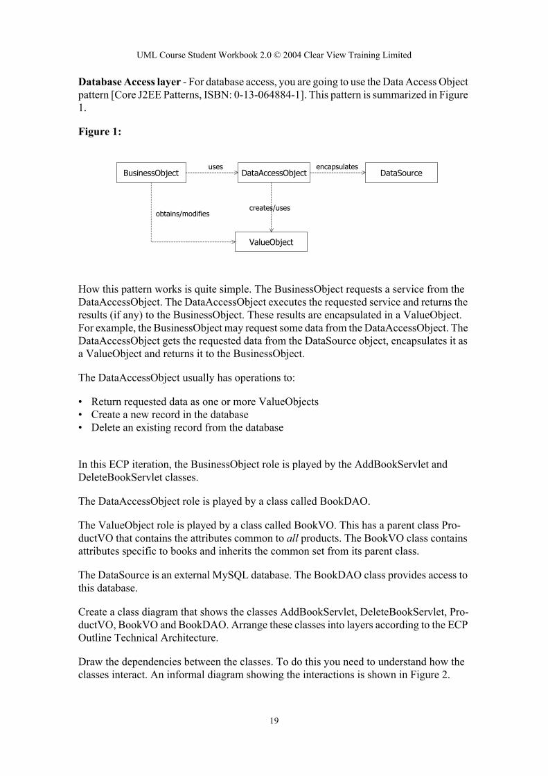
Database Access layer - For database access, you are going to use the Data Access Object pattern [Core J2EE Patterns, ISBN: 0-13-064884-1]. This pattern is summarized in Figure 1.
Figure 1:
How this pattern works is quite simple. The BusinessObject requests a service from the DataAccessObject. The DataAccessObject executes the requested service and returns the results (if any) to the BusinessObject. These results are encapsulated in a ValueObject. For example, the BusinessObject may request some data from the DataAccessObject. The DataAccessObject gets the requested data from the DataSource object, encapsulates it as a ValueObject and returns it to the BusinessObject.
The DataAccessObject usually has operations to:
• Return requested data as one or more ValueObjects• Create a new record in the database• Delete an existing record from the database
In this ECP iteration, the BusinessObject role is played by the AddBookServlet and DeleteBookServlet classes.
The DataAccessObject role is played by a class called BookDAO.
The ValueObject role is played by a class called BookVO. This has a parent class Pro-ductVO that contains the attributes common to all products. The BookVO class contains attributes specific to books and inherits the common set from its parent class.
The DataSource is an external MySQL database. The BookDAO class provides access to this database.
Create a class diagram that shows the classes AddBookServlet, DeleteBookServlet, Pro-ductVO, BookVO and BookDAO. Arrange these classes into layers according to the ECP Outline Technical Architecture.
Draw the dependencies between the classes. To do this you need to understand how the classes interact. An informal diagram showing the interactions is shown in Figure 2.
BusinessObject DataAccessObject DataSource
ValueObject
creates/uses
encapsulatesuses
obtains/modifies
19

UML Course Student Workbook 2.0 © 2004 Clear View Training Limited
class
AddBookS
DeleteBook
BookCatalo
Figure 2:
• The HTML page ManageBookCatalog.html has a form to add a book and a form to delete a book.
• Pressing Add book triggers the AddBookServlet. This servlet gets the book informa-tion from the HTTP request and constructs a BookVO to hold it. It then calls the add-Book(...) operation of the BookDAO passing the new BookVO object as a parameter. The addBook(...) operation creates a new book record in the database from the data held in the BookVO.
• Pressing Delete book triggers the DeleteBookServlet. This servlet gets the books ISBN from the HTTP request and calls the deleteBook(...) operation of the BookDAO passing the ISBN as a parameter. The deleteBook(...) operation deletes the book record with the given ISBN from the database.
Add the following attributes and operations to the design classes::
Table 4:
attributes operations
ervlet none doPost(req, res): voidThis operation is triggered on receipt of an HTTP post message.
Servlet none doPost(req, res): voidThis operation is triggered on receipt of an HTTP post message.
gDAO driver:StringdatabaseUrl:String
BookCatalogDAO()addBook(book: BookVAO): voiddeleteBook(isbn:String): void
Add book
Delete book
ISBN:
ISBN:
Title:
Category:
Authors:
Publisher:
Price:
Description:
Manage Book Catalog
ManageBookCatalog.html
AddBookServlet
DeleteBookServlet
BookVO
BookCatalogDAO
MySQL
updates
HTTP
HTTP
creates
addBook(…)
deleteBook(…)
Image URI:
20

UML Course Student Workbook 2.0 © 2004 Clear View Training Limited
ProductVO le:price,
BookVAO b-
7.4.2 Deliverables
7.5 Sequence diagram - 15 mins
7.5.1 Procedure
You are going to create a Use Case Realisation-design for the use cases AddProductTo-Catalog and DeleteProductFromCatalog for the particular case where the product is a book. Proceed as follows:
• Create a sequence diagram called AddBookToCatalog that shows the interactions between the design classes when the shopkeeper adds a new book to the catalog. The sequence of events is as follows: the Shopkeeper sends the message doPost() to the AddBookServlet. This message contains all of the data for the book. The AddBook-Servlet creates a new BookVO object to hold the data. The AddBookServlet calls the addBook(...) method of the BookCatalogDAO object to add the new book to the data-base.
• Create a sequence diagram called DeleteBookFromCatalog. The sequence of events is as follows: The Shopkeeper sends the message doPost() to the DeleteBookServlet. This message contains the ISBN of the book to be deleted. The DeleteBookServlet calls the deleteBook(...) method of the BookDAO class to delete the book from the database.
7.5.2 Deliverables
productIdentifier:Stringtitle:Stringcategory:Stringprice:doubledescription:String
ProductVO(productIdentifier:String, title:String, category:String, doubdescription:String)Set and get operations for all attributes
authors:Stringpublisher:String
BookVAO(isbn:String, title:String, category:String, authors:String, pulisher:String, price:double, description:String)Set and get methods for all attributessetISBN(isbn:String):void - sets the productIdentifiergetISBN():String - gets the productIdentifier
Deliverables Completed
An updated component diagram.
A design class diagram
Deliverables Completed
A design sequence diagram called AddBookToCatalog
Table 4:
21

UML Course Student Workbook 2.0 © 2004 Clear View Training Limited
A design sequence diagram called DeleteBookFromCatalog.
22

UML Course Student Workbook 2.0 © 2004 Clear View Training Limited
8 Design - state machines lab
8.1 IntroductionIn this Lab, we’re going to explore some of the dynamic aspects of the ECP.
8.2 Order processing - 30 minsOrder processing is an essential part of the ECP. In this lab you will create a state machine for the Order class. To be able to do this, you need to read the following description of how orders are processed:
“An order is opened when the customer checks out. Initially the order is unpaid. The cus-tomer then pays for the order. Payment is always in full. At some point after payment the order is shipped. At any point in time before the order is shipped it may be cancelled. At any point in time before the order is paid for it may be changed. When the order is either shipped or cancelled, it is closed.”
8.2.1 Procedure
Identify the states, events and transitions for the Order class and create a state machine called Order state machine.
Don’t worry about changing the Order yet - you will deal with that in the next lab.
8.2.2 Deliverables
8.3 Adding and removing items from an order - 30 minsWhile the order is open and unpaid, the customer may change the order. This involves the customer:
• Adding an item to the order• Removing an item from the order• Changing the quantity of an item on the order.
If the quantity of an item on the order drops to zero, then it is automatically removed from the order. To keep things simple, assume that there is no undo mechanism for changes made to the order.
8.3.1 Procedure
Deliverables Completed
A state machine for the Order class called Order state machine.
23

UML Course Student Workbook 2.0 © 2004 Clear View Training Limited
Identify the state in the state machine in which the order may be changed. Make this a ref-erence state to refer to a new state machine.
In the new state machine show details of adding and removing items from the order.
8.3.2 Deliverables
Deliverables Completed
Modified Order state machine.
A new state machine for editing the order.
24

UML Course Student Workbook 2.0 © 2004 Clear View Training Limited
9 Deployment - Deployment and implementation lab
9.1 Introduction - ECP deploymentIn this Lab we're going to deploy our vertical slice on some hardware. The next section gives you all the information you need to successfully deploy the first iteration.
9.1.1 ECP deployment strategy
The ECP shall be deployed across three physical machines:
1. Client machines running a web browser. We will assume the client machines are all Windows PCs running IE6. The actual client configuration is not important provided it is running a suitable web browser.
2. A web server machine which is a Linux PC running the open source Tomcat servlet container. This provides the server with the capability to run servlets and JSPs.
3. A Database server machine which is a Linux PC running the open source MySQL RDBMS.
Communication between the client machines and the Web Server is via HTTP (hypertext transfer protocol), which is just the normal web protocol. Communication between the web server and the database server is via HTTPS (the secure sockets layer).
9.2 Nodes - 10 mins
9.2.1 Procedure
Create a descriptor form deployment diagram containing nodes and relationships between nodes for the types of node that the ECP will be deployed on.
Indicate on the relationships the type of communication used.
Hints:
• Identify the devices and the execution environments. Don’t bother modeling the oper-ating system as a seperate execution environment, just have a device node called something like WindowsPC or LinuxPC.
• For a descriptor form deployment diagram you have a single node for each type of device and for each type of execution environment.
9.2.2 Deliverables
Deliverables Completed
25
UML Course Student Workbook 2.0 © 2004 Clear View Training Limited
9.3 Components - 10 mins
9.3.1 Procedure
Update your deployment diagram by assigning the components you identified earlier to the nodes.
Hint: Use a “black-box” view of the components so that you don’t have to show nested components.
9.3.2 Deliverables
A descriptor form deployment diagram containing nodes and relation-ships between nodes.
Deliverables Completed
A descriptor form deployment diagram showing nodes, components and relationships.
26

UML Course Student Workbook 2.0 © 2004 Clear View Training Limited
Appendix 1 ECP Informal System Specification
A1.1 IntroductionThe Informal System Specification is, in this case, merely a sketch of what the system should do. Fortunately, there are many websites that already sell books and CDs and so the analysis problem shouldn't be particularly difficult. We can fill in any gaps in our knowledge by getting ideas from competitor's sites, always being careful not to infringe any patents or copyrights.
A1.2 The specification document
Clear View Training E-Commerce PlatformInformal System Specification
VisionThe E-Commerce Platform (ECP) is a new web-based selling channel for Clear View Train-ing Limited.
The goal of the ECP is to allow Clear View Training customers to order products via the Internet from an online catalogue.
The ECP must integrate with the existing inventory and dispatch systems and must also communicate credit card information to the credit card processing company for validation before an order is accepted.
We believe that the system should operate according to the “shopping basket” paradigm that other very successful web stores such as Amazon.com use. In this model a catalog of prod-ucts is displayed and the users can click on “Add to basket” to place a product in their shop-ping basket. This idea is demonstrated in the user interface prototype.
User Interface PrototypeThe prototype is currently just a set of browser screens created in Microsoft Visio that can be found in the document “ECP User Interface Prototype.doc”.
Clear View Training ProductsAt this time, Clear View Training only intends to sell books and CDs via its ECP web chan-nel.
BooksBooks are categorized according to subject matter. These categories include, but are not lim-ited to:
Table 1 - Book Categories
ArtBiographiesChildren’s booksFinanceComputersCooking, food & wineEntertainmentMind & body
HistoryHobbiesHome & gardenHorrorLiterature & fictionMystery & thrillersNon-fictionProfessional & technical
ReferenceReligion & spiritualityScience & natureScience fictionSports & outdoorsTravel
30
UML Course Student Workbook 2.0 © 2004 Clear View Training Limited
Each book is identified by its ISBN.
Customers can browse the book catalog by category or find a given book based on the fol-lowing search criteria:
• Author• Title• Publisher• ISBN
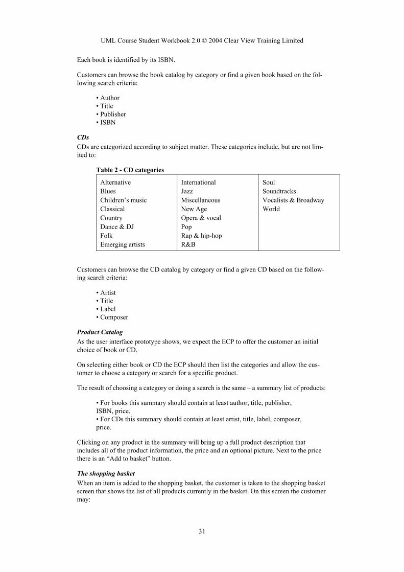
CDsCDs are categorized according to subject matter. These categories include, but are not lim-ited to:
Table 2 - CD categories
Customers can browse the CD catalog by category or find a given CD based on the follow-ing search criteria:
• Artist• Title• Label• Composer
Product CatalogAs the user interface prototype shows, we expect the ECP to offer the customer an initial choice of book or CD.
On selecting either book or CD the ECP should then list the categories and allow the cus-tomer to choose a category or search for a specific product.
The result of choosing a category or doing a search is the same – a summary list of products:
• For books this summary should contain at least author, title, publisher, ISBN, price.• For CDs this summary should contain at least artist, title, label, composer, price.
Clicking on any product in the summary will bring up a full product description that includes all of the product information, the price and an optional picture. Next to the price there is an “Add to basket” button.
The shopping basketWhen an item is added to the shopping basket, the customer is taken to the shopping basket screen that shows the list of all products currently in the basket. On this screen the customer may:
AlternativeBluesChildren’s musicClassical CountryDance & DJFolkEmerging artists
InternationalJazzMiscellaneousNew AgeOpera & vocalPopRap & hip-hopR&B
SoulSoundtracksVocalists & BroadwayWorld
31

UML Course Student Workbook 2.0 © 2004 Clear View Training Limited
• Remove an item from the basket• Change the quantity of an item• Proceed to checkout
CheckoutThe system presents the customer with a summary of their order. If they click on “confirm” to confirm the order, then the system asks them to log in if they have not already done so.
Ideally, the checkout should recognize the customer in which case the log in is automatic.
If not, then existing customers must log in by entering a user name and password.
New customers must fill out a form that asks for the following details:
• Name• Address• Shipping address (if different from above)• Email address• Phone number• Fax number• Credit card details
On submitting this form, the customer will be issued with a user name (which should proba-bly be their email address) and is asked to select a password.
Order processing then completes.
32

UML Course Student Workbook 2.0 © 2004 Clear View Training Limited
Appendix 2 ECP User Interface Prototype
A2.1 IntroductionThe ECP UI prototype shows some of the expected web pages that will form the basis of the user interface of the ECP. This prototype is very much a first draft - it is incomplete and inconsistent and was produced very quickly in Microsoft Visio to give the stakehold-ers some sort of idea about what the ECP would finally look like. It is quite typical of the sort of document that might be available to you at the beginning of analysis.
In the next few sections, we document each of the screens in the prototype.
A2.2 Clear View Training Home PageThis is the home page for the site.
Figure 1:
Browser
Clear View Training Home Page
Books CDs Basket
Buy book Buy CD
Contact us:Telephone: 0123456Fax: 0123456Postal address: 123 Web Way, Harrow, EnglandEmail: [email protected]
33

UML Course Student Workbook 2.0 © 2004 Clear View Training Limited
A2.3 BooksThis page allows the user to select a category of books to view, or to perform a search on the whole catalogue.
Figure 2:
Browser
Books
Home CDs Basket
Browse books by category:
ArtBiographiesChildren'sFinanceComputersFood & wineEntertainmentMind & body
HistoryHobbies HomeHorror FictionMystery Non-fictionTechnical
ReferenceReligionScienceScience fictionSportsOutdoorsTravel
Or search for a book:
Find book
authortitle
publisher
ISBN
34

UML Course Student Workbook 2.0 © 2004 Clear View Training Limited
A2.4 Computers CategoryThis is an example of the type of page that the user would see if they selected the Com-puters category from the Books page. It provides an exemplar for all the other categories.
Figure 3:
Browser
Home CDs BasketBooks
Next >
UML and the Unified Process
Jim Arlow, Ila Neustadt
Addison Wesley, ISBN: 0201770601
$44.99
Add to basket
Unified Modeling Language Reference Manual
James Rumbaugh, Ivar Jacobson, Grady Booch
Addison Wesley, ISBN: 020130998X
$57.99
Unified Modeling Language User Guide
Grady Booch, Ivar Jacobson, James Rumbaugh
Addison Wesley, ISBN: 0201571684
$49.95
Advanced Use Case Modeling
Frank Armour, Granville Miller
Addison Wesley, ISBN: 0201615924
$34.95
Design Patterns
Gamma, Helm, Johnson, Vlissides
Addison Wesley, ISBN: 0201633612
$49.95
Add to basket
Add to basket
Add to basket
Add to basket
35

UML Course Student Workbook 2.0 © 2004 Clear View Training Limited
A2.5 Your SelectionThis is the type of page the user would see if they selected a particular book from the Com-puters page.
Figure 4:
Browser
Home CDs BasketBooks
Comments: *****
This book meets a need that many other books have notreally fulfilled. There has been a need for a comprehensiveguide that bridges the theoretical world of modelling and thepractical aspects of delivering a solution.
UML and the Unified Process
Jim Arlow, Ila Neustadt
Addison Wesley, ISBN 0201770601
$44.99 Add to basket
36

UML Course Student Workbook 2.0 © 2004 Clear View Training Limited
A2.6 Your BasketThe user’s shopping basket. This contains a list of the products that they have selected.
Figure 5:
Browser
Your BasketHome CDs BasketBooks
Product ID Description Price
UML and the Unified Process020130998X $44.99
Design Patterns0201633612 $49.95
Total $94.94
< Back
Quantity
1
1
37

UML Course Student Workbook 2.0 © 2004 Clear View Training Limited
A2.7 Here is your orderThis is the checkout page, it displays the users final order and asks for confirmation.
Figure 6:
Browser
Here is your order:
Product ID Description Price
UML and the Unified Process020130998X $44.99
Design Patterns0201633612 $49.95
Total
$0.00
Quantity
1
1
Shipping $5.00
Tax
$99.94
38

UML Course Student Workbook 2.0 © 2004 Clear View Training Limited
Appendix 3 ECP Outline Technical Architecture
A3.1 IntroductionThis short technical architecture for the ECP details the architectural decisions that we have made.
Don’t worry to much about the section on J2EE Architectural Patterns, you’ll see what these mean when you do the exercise!
ECP Software Architecture Document version 1.1
IntroductionThe E-Commerce Platform (ECP) is a new web-based selling channel for Clear View Train-ing. This channel will sell books and CDs.
This document describes the software architecture for the whole ECP.
Definitions, Acronyms, Abbreviations
References[R1] to [RN] - References a specific numbered requirement in the “ECP Supplementary Requirements Specification version 1.1”.
[Alur] - Core J2EE Patterns, Deepak Alur et al., Sun Microsystems Press, 2001, ISBN0130648841
Architectural constraintsThe ECP shall have a web-browser based interface [R34], [R35], [R36].
The ECP shall be written in Java [R37].
The ECP must run on the same architecture as the existing Clear View Training web site [R38]. This means that we must use the following software:
Term Definition
ECP The Clear View Training E-Commerce Platform.
JSP JavaServer Page
Software Reference Details
Apache www.apache.org Open source web server.
Tomcat http://jakarta.apache.org/tom-cat/
Open source JSP and servlet container. Used by the Apache web server to process servlets and JSPs.
MySQL www.mysql.org Open source relational data-base.
MySQL Con-nector/J
www.mysql.org Open source JDBC driver for the MySQL database.
39

UML Course Student Workbook 2.0 © 2004 Clear View Training Limited
PatternsWe will use the following J2EE architectural patterns from [Alur].
Architectural styleWe will adopt the following architectural style:
Pattern name Tier Synopsis
Front Controller Presentation Provides a centralized controller for man-aging the handling of a request. We envi-sion one servlet controller for customers and another for users of the system.
View Helper Presentation Encapsulates logic that is not related to presentation formatting into helper com-ponents. We will implement helper com-ponents as custom tag libraries or JavaBeans.
Value List Handler Business Manages query execution, results cach-ing, and results processing. We will implement Value List Handler compo-nents as custom tag libraries.
Data Access Object Data Access Abstracts data sources; provides transpar-ent access to data. Individual products will be represented by a data access object.
Style Synopsis
Separate HTML mark-up from Java code
We will use HTML pages, servlets, Java Server Pages and custom Java tag libraries to allow the separation of HTML mark-up and Java code. All Java code will be encapsulated into a custom tag library. This will allow HTML pages to be designed by Web designers who do not know Java.
40
UML Course Student Workbook 2.0 © 2004 Clear View Training Limited
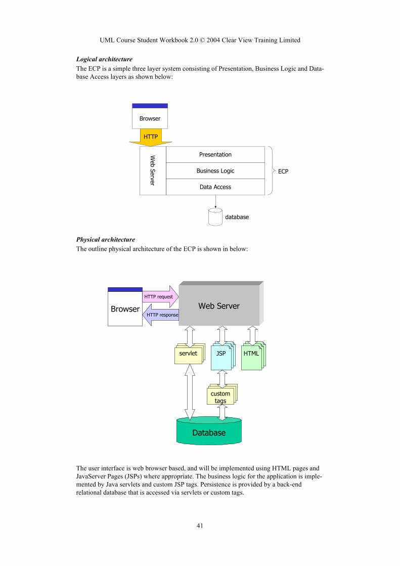
Logical architectureThe ECP is a simple three layer system consisting of Presentation, Business Logic and Data-base Access layers as shown below:
Physical architectureThe outline physical architecture of the ECP is shown in below:
The user interface is web browser based, and will be implemented using HTML pages and JavaServer Pages (JSPs) where appropriate. The business logic for the application is imple-mented by Java servlets and custom JSP tags. Persistence is provided by a back-end relational database that is accessed via servlets or custom tags.
Browser
Presentation
Business Logic
Data Access
Web Server
HTTP
ECP
database
Web ServerBrowser
HTTP request
servletJSPJSPJSP
JSPJSPHTML
HTTP response
customtags
Database
41

UML Course Student Workbook 2.0 © 2004 Clear View Training Limited
JavaServer Pages are dynamic HTML pages that can include Java code or custom tags writ-ten in Java. The Java code or tags are executed on the server before the page is served to the browser. This makes JSPs the ideal technical solution for including dynamic elements (such as information from a back-end database) into HTML pages.
According to our architectural style, there will be no direct access to the database from HTML code or from JSPs - all database access is mediated by a servlet or a custom tag library. This means that the various types of components are distributed amongst the logical layers as follows.
Layer Component
Presentation HTML pages, JSPs
Business Logic Servlets
Data Access java classes, custom tag libraries
42