Embed Size (px)
Citation preview

1
Module 2:Introduction to UML
Background What is UML for? Building blocks of UML UML Diagrams

2
References
Documentation on UML is available from:UML 1.5:
http://www.omg.org/technology/documents/formal/uml.htm
UML 2.0: http://www.uml.org/
Rational Rose is available from: http://www.rational.com
Visual Modeling with Rational Rose and UML, Terry Quatrani, 1998.

3
Overview
Background What is UML for? Building blocks of UML Process for Using UML

4
What is UML? The Unified Modelling Language is a standard graphical language for modelling object oriented software
At the end of the 1980s and the beginning of 1990s, the first object-oriented development processes appeared
The proliferation of methods and notations tended to cause considerable confusion
Two important methodologists Rumbaugh and Booch decided to merge their approaches in 1994.
They worked together at the Rational Software Corporation In 1995, another methodologist, Jacobson, joined the team
His work focused on use cases In 1997 the Object Management Group (OMG) started the process of
UML standardization

5
What is UML?
The Unified Modeling Language (UML) is a language for specifying, visualizing, constructing, and documenting the artifacts of software systems, as well as for business modeling.

6
UUMMLL
Unified:• Unifies all existing previous
Notations
~~~~ Modeling:Modeling:
• Used for Modeling Software ArtifactsUsed for Modeling Software Artifacts
Language: Language: • Means of CommunicationMeans of Communication~~

7
UML is a language for:
Visualizing: Graphical models with precise semantics
Specifying: Models are precise, unambiguous and complete to capture all important Analysis, Design, and Implementation decisions.
Constructing: Models can be directly connected to programming languages, allowing forward and reverse engineering
Documenting: Diagrams capture all pieces of information collected by development team, allowing to share and communicate the embedded knowledge.

8
Unified Modeling Language (UML)
An effort by IBM (Rational) – OMG to standardize OOA&D notation
Combine the best of the best from Data Modeling (Entity Relationship Diagrams);
Business Modeling (work flow); Object Modeling
Component Modeling (development and reuse - middleware, COTS/GOTS/OSS/…:)
Offers vocabulary and rules for communication Not a process but a language
de facto industry standard

9
UML History OO languages appear mid 70’s to late 80’s Between ’89 and ’94, OO methods increased from 10 to 50. Unification of ideas began in mid 90’s.
Rumbaugh joins Booch at Rational ’94 v0.8 draft Unified Method ’95 Jacobson joins Rational ’95 UML v0.9 in June ’96 UML 1.0 offered to OMG in January ’97 UML 1.1 offered to OMG in July ’97 Maintenance through OMG RTF UML 1.2 in June ’98 UML 1.3 in fall ’99 UML 1.5 UML 2.0 underway
Rational now has Grady Booch - Fusion James Rumbaugh – Object Modeling Technique (OMT) Ivar Jacobson – Object-oriented Software Engineering: A Use Case Approach (Objectory) ( And David Harel - StateChart)

10
UML is for Visual Modeling
Business Process
Places Order
Item
Ships the Item
- standard graphical notations: Semi-formal- for modeling enterprise info. systems, distributed Web-based applications, real time embedded systems, …
A picture is worth a thousand words!
via
Fulfill Order
Customer
Sales Representative
- Specifying & Documenting: models that are precise, unambiguous, complete UML symbols are based on well-defined syntax and semantics. analysis, architecture/design, implementation, testing decisions.
- Construction: mapping between a UML model and OOPL.

11
UML is also for …
Specifying building models that are: Precise, Unambiguous, Complete UML symbols are based on well-defined syntax and semantics. UML addresses the specification of all important analysis, design, and
implementation decisions.
Constructing Models are related to OO programming languages. Round-trip engineering requires tool and human intervention to avoid information loss
Forward engineering — direct mapping of a UML model into code. Reverse engineering — reconstruction of a UML model from an
implementation.
Documenting Architecture, Requirements, Tests, Activities (Project planning, Release management)
12
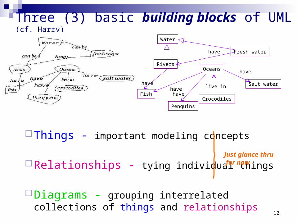
Three (3) basic building blocks of UML (cf. Harry)
Things - important modeling concepts
Relationships - tying individual things
Diagrams - grouping interrelated collections of things and relationships
Just glance thru for now
Water
RiversOceans
Fish
Penguins
Crocodiles
Fresh water
Salt waterhavehave
have
live in
have
have

13
UML 1.x Structural — nouns/static of UML models (irrespective of time).
Behavioral — verbs/dynamic parts of UML models.
Grouping — organizational parts of UML models.
Annotational — explanatory parts of UML models.
3 basic building blocks of UML - Things
Main

14
Nouns. Conceptual or physical elements.
Structural Things in UML- 7 Kinds (Classifiers)
Studentstd_idgrade
changeLevel( )setGrade( )getGrade( )
IGrade
Manage CourseRegistration
Registerfor Courses
Event MgrthreadtimeStart
suspend( )stop( )
Course.cpp
Class
Interface
CollaborationUse Case
Active Class (processes/threads)
Component Node
UnivWebServer<<interface>>IGrade
setGrade()getGrade()
(collection of externallyVisible ops)
(chain of responsibility shared by a web of interacting objects, structural and behavioral)
(a system service-sequence of Interactions w. actor)
(replaceable part,realizes interfaces)
(computational resource at run-time,processing powerw. memory)
15
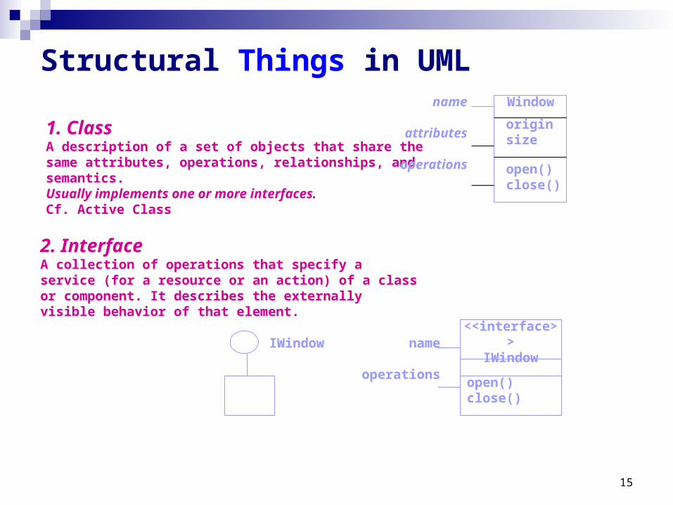
1. ClassA description of a set of objects that share the same attributes, operations, relationships, and semantics.Usually implements one or more interfaces. Cf. Active Class
Window
originsize
open()close()
name
attributes
operations
Structural Things in UML
2. InterfaceA collection of operations that specify a service (for a resource or an action) of a class or component. It describes the externally visible behavior of that element.
<<interface>>IWindow
open()close()
name
operations
IWindow

16
Chain ofResponsibility
Define an interaction among a web of objects.Define a society of roles and other elements.Provide cooperative behavior.Capture structural and behavioral dimensions.
3. Collaboration
Structural Things in UML
Place Order
A sequence of actions that produce an observable result for a specific actor.Provides a structure for behavioral things.Realized through a collaboration (usually realized by a set of actors and the system to be built).
4. Use Case
Order management
Order validation
<<refine>>

17
Special class whose objects own one or more processes or threads.
Can initiate control activity.
Event Manager
suspend()flush()
nameattributes
operationsHeavy border
5. Active Class
Structural Things in UML
Threadtime
Orderform.java
Replaceable part of a system.Components can be packaged logically.Conforms to a set of interfaces.Provides the realization of an interface.
6. Component
WebServerElement that exists at run time.Represents a computational resource.Generally has memory and processing power.
7. Node
Variations on Structural Things: Actors, Signals, Utilities, Processes & Threads, Applications, Documents, etc.

18
Behavioral Things in UML
Two primary kinds of behavioral things:
Verbs. Dynamic parts of UML models: “behavior over time” Usually connected to structural things.
Interactiona set of objects exchanging messages, to accomplish a specific purpose.
ask-for-an-A
State Machinespecifies the sequence of states an object or an interaction goes through during its lifetime in response to events.
inPartyinStudy
harry: Student
name = “Harry Kid”
katie: Professor name = “Katie Holmes”
received-an-A/buy-beer
sober/turn-on-PC

19
Packages - one primary kind of grouping. - General purpose mechanism for organizing elements into groups.
- Purely conceptual; only exists at development time.- Contains behavioral and structural things.- Can be nested.- Variations of packages are: Frameworks, models, & subsystems.
Meeting Scheduler
Grouping Things in UML
20
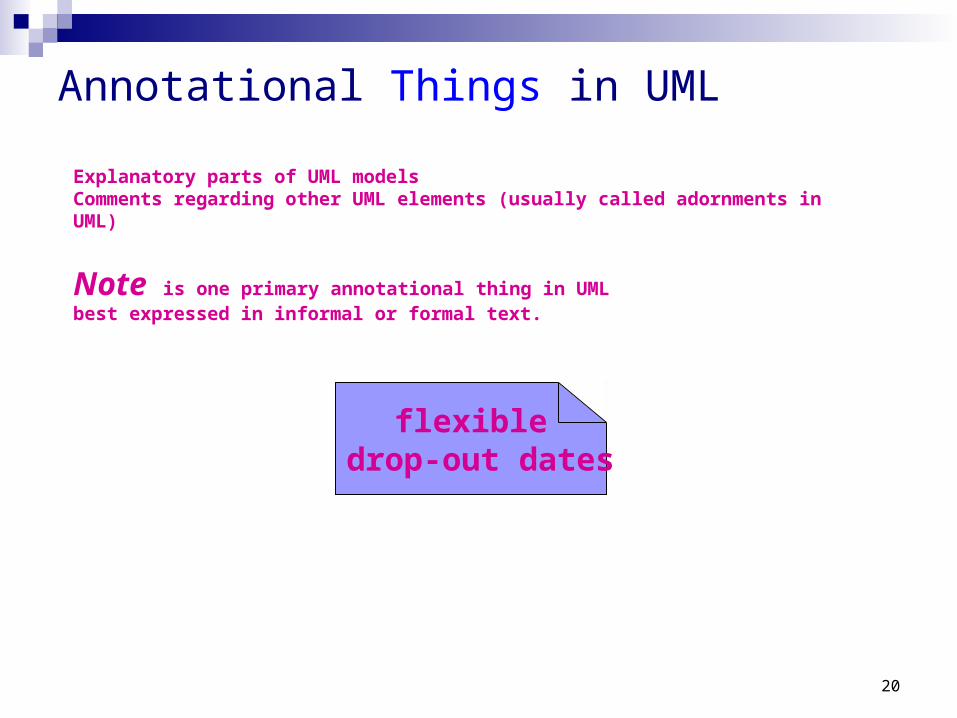
Annotational Things in UML
flexible drop-out dates
Explanatory parts of UML modelsComments regarding other UML elements (usually called adornments in UML)
Note is one primary annotational thing in UMLbest expressed in informal or formal text.

21
- For organizing elements (structural/behavioral) into groups. - Purely conceptual; only exists at development time.
- Can be nested.- Variations of packages are: Frameworks, models, & subsystems.
Course Manager
Grouping Things in UML: Packages
Annotational Things in UML: Note
- Explanatory/Comment parts of UML models - usually called adornments - Expressed in informal or formal text.
flexible drop-out dates
Course Manager
University Administration
Student Admission
-Student+Department
operation(){for all g in children g.operation()}

22
3 basic building blocks of UML - Relationships
4 Kinds
Dependency Association Generalization Realization

23
2. Associationsa structural relationship that describes a set of links, a link being a connection between objects.
Can be directed labels Can have multiplicity & role names
1. Dependencya semantic relationship between two things in which a change to one thing (independent) may affect the semantics of the other thing (dependent).
Relationships in UML
Directed is optional and label is optional.
0..1
employer
*
employee
Aggregation a special kind of association. It represents a structural relationship between the whole and its parts.
Represented by a diamond.

24
Relationships in UML
3. Generalizationa specialization/generalization relationship in which objects of the specialized element (the child) are more specific than the objects of the generalized element.
4. Realizationa semantic relationship between two elements, wherein one element guarantees to carry out what is expected by the other element.
Where?
Between interfaces and classes that realize them…Between use cases and the collaborations that realize them...

25
3 basic building blocks of UML - Relationships
1. AssociationsStructural relationship that describes a set of links, a link being a connection between objects.
4. Dependencya change to one thing (independent) may affect the semantics of the other thing (dependent).(direction, label are optional)
variants: aggregation & composition
2. Generalizationa specialized element (the child) is more specific the generalized element.
3. Realizationone element guarantees to carry out what is expected by the other element. (e.g, interfaces and classes/components; use cases and collaborations)
Student University
Student Person
Student
IGrade
Studentharry: Student <<instanceOf>>
attends

26
3 basic building blocks of UML - Diagrams
A connected graph: Vertices are things; Arcs are relationships/behaviors.
UML 2.0: 12 diagram types
Behavioral DiagramsRepresent the dynamic aspects.
Use case Sequence;
Collaboration Statechart Activity
Structural DiagramsRepresent the static aspects of a system.
Class;
Object Component Deployment
Behavioral Diagrams
Use case
Statechart Activity
Structural Diagrams
Class;
Object Component Deployment Composite Structure Package
Interaction Diagrams
Sequence;
Communication
Interaction Overview Timing
UML 1.x: 9 diagram types.

27
UML diagrams
• Class diagrams
—describe classes and their relationships
• Interaction diagrams
—show the behaviour of systems in terms of how objects interact with each other
• State diagrams and activity diagrams
—show how systems behave internally
• Component and deployment diagrams
—show how the various components of systems are arranged logically and physically

28
Diagrams in UML – University Registration System as a Running Example
The SMU wants to computerize its registration system The Registrar sets up the curriculum for a semester
One course may have multiple course offerings Students select four (4) primary courses and two (2) alternate courses Once a student registers for a semester, the billing system is notified so the
student may be billed for the semester Students may use the system to add/drop courses for a period of time after
registration Professors use the system to set their preferred course offerings and receive
their course offering rosters after students register Users of the registration system are assigned passwords which are used at
logon validation

29
Diagrams in UML – Actors in Use Case Diagram
Student
RegistrarProfessor
Billing System
An actor is someone or some thing that must interact with the system under development

30
Diagrams in UML - Use Cases in Use Case Diagram
Register for CoursesMaintain Curriculum Request Course Roster
A use case is a pattern of behavior the system exhibits– Each use case is a sequence of related transactions performed by an actor and the system in a dialogue
Actors are examined to determine their needs– Registrar -- maintain the curriculum
– Professor – set course offerings and request roster
– Student -- register for courses
– Billing System -- receive billing information from registration

31
Diagrams in UML - Use Case Diagram
Use case diagrams are created to visualize the relationships between actors and use cases
Student
Registrar
Professor
Register for Courses
Maintain Curriculum
Request Course Roster
Billing System
Set Course Offerings
Duplication?
32
Diagrams in UML - Documenting Use Cases in Use Case Diagram
A flow of events is described in documents for each use case Written from an actor point of view
Details what the system must provide to the actor when the use case is executed
Typical contents How the use case starts and ends Normal flow of events Alternate flow of events Exceptional flow of events

33
Diagrams in UML– Flow of Events for Maintaining Curriculum and Setting Course Offerings
This use case begins when the Registrar logs onto the Registration System and enters his/her password.
The system verifies that the password is valid and prompts the Registrar to select the current semester or a future semester.
The Registrar enters the desired semester.
Flow of Events for Setting Course Offerings
The system prompts the professor to select the desired activity: ADD, DELETE, REVIEW, or QUIT.
If the activity selected is ADD: Add a Course subflow is performed. If the activity selected is DELETE: Delete a Course subflow is performed. If the activity selected is REVIEW: Review Curriculum subflow is performed. If the activity selected is QUIT, the use case ends.
(Maintaining Curriculum and Setting Course Offerings are two of the activities in running university registration system)
Flow of Events for Maintaining CurriculumRegistrar Maintain Schedule
ProfessorSet Course Offerings

34
Diagrams in UML - Uses and Extends Use Case Relationships in Use Case Diagram
A uses relationship shows behavior common to one or more use cases
An extends relationship shows optional behavior
Register for courses
<<uses>>
Logon validation<<uses>>
Maintain curriculum
Register for Distance Learning courses
<<extends>>

35
Diagrams in UML - Use Case Realizations
Interaction diagrams describe how use cases are realized as interactions among societies of objects, including the messages that may be dispatched among them. They address the dynamic view of the system.
Two types of interaction diagrams Sequence diagrams Collaboration diagrams
A use case diagram presents an outside view of the system.
Then, how about the inside view of the system?

36
Diagrams in UML - Sequence Diagram
A sequence diagram displays object interactions arranged in a time sequence
: Student registration form
registration manager
math 101
1: fill in info
2: submit
3: add course(Sue, math 01)
4: are you open?5: are you open?
6: add (Sue)7: add (Sue)
math 101 section 1
Which use case is this for?

37
: Registrar
course form : CourseForm
theManager : CurriculumManageraCourse :
Course
1: set course info2: process
3: add course
4: new course
Diagrams in UML - Collaboration Diagram Displays object interactions organized around objects and their direct
links to one another. Emphasizes the structural organization of objects that send and
receive messages.
Which use case is this for?

38
Diagrams in UML - Class Diagrams
A class diagram shows the existence of classes and their relationships in the logical view of a system
UML modeling elements in class diagrams Classes and their structure and behavior Association, aggregation, dependency, and inheritance relationships Multiplicity and navigation indicators Role names

39
Diagrams in UML - Classes
A class is a collection of objects with common structure, common behavior, common relationships and common semantics
Some classes are shown through the objects in sequence and collaboration diagram
A class is drawn as a rectangle with three compartments Classes should be named using the vocabulary of the domain
Naming standards should be created e.g., all classes are singular nouns starting with a capital letter

40
Diagrams in UML - Classes: Naming & 3 Sections
RegistrationForm
RegistrationManager
Course
Student
CourseOfferingProfessor
ScheduleAlgorithm
Which sequence/collaboration diagram are these from?

41
Operations • The behavior of a class is represented by its operations
• Operations may be found by examining interaction diagrams
registration form
registration manager
3: add course(Sue, math 01)
RegistrationManager
addCourse(Student,Course)
Diagrams in UML – Classes: Operations & Attributes
Attributes • The structure of a class is represented by its attributes
• Attributes may be found by examining class definitions, the problem requirements, and by applying domain knowledge
Each course offeringhas a number, location and time
CourseOfferingnumberlocationtime

42
Diagrams in UML – Some Classes with Operations & Attributes
RegistrationForm
RegistrationManager
addStudent(Course, StudentInfo)Course
namenumberCredits
open()addStudent(StudentInfo)
Studentnamemajor
CourseOfferinglocation
open()addStudent(StudentInfo)
ProfessornametenureStatus
ScheduleAlgorithm

43
Diagrams in UML – Object Diagrams
• Shows a set of objects and their relationships. • A static snapshot of instances.
Harry (Student)
Name: “Harry Mat”Major: CS
Sue (Professor)
Name: “Sue Becker”tenureStatus: true

44
Registration Manager
Math 101: Course
3: add student(Sue)
RegistrationManager
Course
• Relationships are discovered by examining interaction diagrams– If two objects must “talk” there must be a pathway for communication
Diagrams in UML – Finding Relationships

45
RegistrationForm
RegistrationManager
Course
Student
CourseOfferingProfessor
addStudent(Course, StudentInfo)
namenumberCredits
open()addStudent(StudentInfo)
major
location
open()addStudent(StudentInfo)
tenureStatus
ScheduleAlgorithm
10..*
0..*
1
1
1..*4
3..10
0..41
Diagrams in UML – Relationships: Multiplicity and Navigation
?

46
RegistrationForm
RegistrationManager
Course
Student
CourseOfferingProfessor
addStudent(Course, StudentInfo)
namenumberCredits
open()addStudent(StudentInfo)
major
location
open()addStudent(StudentInfo)
tenureStatus
ScheduleAlgorithm
nameRegistrationUser
Diagrams in UML – Inheritance
• Inheritance is a relationship between a superclass and its subclasses
• Common attributes, operations, and/or relationships are shown at the highest applicable level in the hierarchy

47
InitializationOpen
entry: Register studentexit: Increment count
Closed
Canceled
do: Initialize course
do: Finalize course
do: Notify registered students
Add Student / Set count = 0
Add student[ count < 10 ]
[ count = 10 ]
Cancel
Cancel
Cancel
Diagrams in UML – State Transition Diagram• The life history of a given class• The events that cause a transition from one state to another• The actions that result from a state change
What class is this for?

48
Diagrams in UML – Statechart Diagram
• shows a state machine, consisting of states, transitions, events and activities
Cancelled
Initialization Open
Closed
Add student / Set count = 0
Add student[ Count < 10 ]
Cancel course
Cancel course
[ Count = 10 ] ^CourseReport.Create report
What’s the difference between a state transition diagram and a StateChart?
49
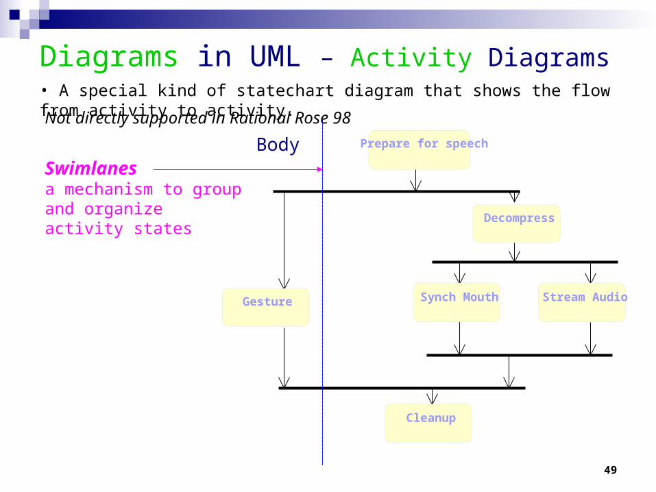
Diagrams in UML – Activity Diagrams• A special kind of statechart diagram that shows the flow from activity to activity.
Not directly supported in Rational Rose 98
BodySwimlanesa mechanism to group and organize activity states
Prepare for speech
Decompress
Synch Mouth Stream Audio
Cleanup
Gesture

50
Diagrams in UML – Activity Diagrams
Place a state at each synchronization bar!
How do we represent these if not supported by UML, or Rational Rose?
Synchronization
This is the result (Can you figure this out?)
Prepare for speech
Decompress
Synch Mouth Stream Audio
Cleanup
Gesture
Gesture
Prepare for speech
Decompress
Synch Mouth Stream Audio
Cleanup
Sync 1
Sync 2
sync3
Sync 4

51
Course CourseOffering
Student Professor
Course.dllCourse
People.dllUser
Register.exeBilling.exeBillingSystem
Diagrams in UML – Component Diagram
• shows the organizations and dependencies among a set of components.
Registrar.exe
Courses.dll
People.dll

52
Registration Database
Library
Dorm
Main Building
Diagrams in UML – Deployment Diagram
• The deployment diagram shows the configuration of run-time processing elements and the software processes living on them.
• The deployment diagram visualizes the distribution of components across the enterprise.

53
• Stereotypes can be used to extend the UML notational elements• Stereotypes may be used to classify and extend associations,
inheritance relationships, classes, and components• Examples:
– Class stereotypes: boundary, control, entity, utility, exception
– Inheritance stereotypes: uses and extends
– Component stereotypes: subsystem
Extensibility of UML
Stereotypes — extends vocabulary.Tagged values — extends properties of UML building blocks.Constraints — extend the semantics of UML building blocks.

54
Using UML Concepts in a Nutshell
Display the boundary of a system & its major functions using use cases and actors
Illustrate use case realizations with interaction diagrams Represent a static structure of a system using class diagrams Model the behavior of objects with state transition diagrams Reveal the physical implementation architecture with component &
deployment diagrams Extend your functionality with stereotypes

55
• main reason for using the iterative life cycle:– Not all the needed information up front– Changes throughout the development period
• expect – To face some persistent, recurring risks – To discover new risks along the way– To do some rework; to throw away some lines of code– To change requirements along the way
Process for Using UML - But No Silver Bullet

56
Summary
Background
What is UML for?
for visualizing, specifying, constructing, and documenting models
Building blocks of UML Things, Relationships (4 kinds) and Diagrams (7 different kinds)
Process for Using UML Use case-driven, Architecture-centric, & Iterative and incremental

57
Points to Ponder How much unification does UML do? Consider the Object Model Notation on the inside cover on the front and back of the textbook
"Object Oriented Modeling and Design" by Rumbaugh, et.al. 1. List the OMT items that do not exist in UML 2. List the UML items that do not exist in OMT3. For those items of OMT for which UML equivalents exist, map the notation to UML.
Where would you want to use stereotypes? Model the “Business Process” on page 6 in UML. Map the four (4) phases of the RUP to the traditional software lifecycle. If an object refers to a concept, can an object refer to a concept of an
concept? Consider some examples. What would be the essential differences between a property and an
attribute? Consider some examples. What is the syntax and semantics of a class diagram? In Component-Based Software Engineering (CBSE), components are the
units, or building blocks, of a (distributed) software system. What kind of building blocks of UML can be components for CBSE?

58
Module 2:Introduction to UML - Appendix
59
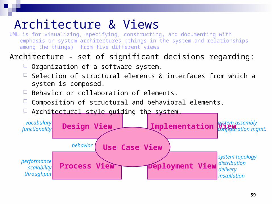
Architecture & Views
Deployment ViewProcess View
Design View Implementation View
Use Case View
vocabularyfunctionality
performancescalability
throughput
behavior
system assemblyconfiguration mgmt.
system topologydistributiondeliveryinstallation
UML is for visualizing, specifying, constructing, and documenting with emphasis on system architectures (things in the system and relationships among the things) from five different views
Architecture - set of significant decisions regarding: Organization of a software system. Selection of structural elements & interfaces from which a system is composed. Behavior or collaboration of elements. Composition of structural and behavioral elements. Architectural style guiding the system.

60
Views
Use Case View
Use Case Analysis is a technique to capture business process from user’s perspective. Encompasses the behavior as seen by users, analysts and testers. Specifies forces that shape the architecture. Static aspects captured in use case diagrams. Dynamic aspects captured in interaction diagrams, statechart diagrams, and activity
diagrams.
Design View Encompasses classes, interfaces, and collaborations that define the vocabulary of a
system. Supports functional requirements of the system. Static aspects captured in class diagrams and object diagrams. Dynamic aspects captured in interaction, statechart, and activity diagrams.

61
Views
Process View Encompasses the threads and processes defining concurrency and synchronization. Addresses performance, scalability, and throughput. Static and dynamic aspects captured as in design view; emphasis on active classes.
Implementation View Encompasses components and files used to assemble and release a physical system. Addresses configuration management. Static aspects captured in component diagrams. Dynamic aspects captured in interaction, statechart, & activity diagrams.
Deployment View Encompasses the nodes that form the system hardware topology. Addresses distribution, delivery, and installation. Static aspects captured in deployment diagrams. Dynamic aspects captured in interaction, statechart, & activity diagrams.

62
Rules of UML
Well formed models — semantically self-consistent and in harmony with all its related models.
Semantic rules for: Names — what you can call things.
Scope — context that gives meaning to a name.
Visibility — how names can be seen and used. Integrity — how things properly and consistently relate to one another.
Execution — what it means to run or simulate a dynamic model.
Avoid models that are
Elided — certain elements are hidden for simplicity.
Incomplete — certain elements may be missing.
Inconsistent — no guarantee of integrity.

63
Process for Using UML
How do we use UML as a notation to construct a good model?
Use case driven — use cases are primary artifact for defining behavior of the system.
Architecture-centric — the system’s architecture is primary artifact for conceptualizing, constructing, managing, and evolving the system.
Iterative and incremental — managing streams of executable releases with increasing parts of the architecture included.
The Rational Unified Process (RUP)

64
• It is planned, managed and predictable …almost• It accommodates changes to requirements with less disruption• It is based on evolving executable prototypes, not documentation• It involves the user/customer throughout the process• It is risk driven
Process for Using UML - Iterative Life Cycle
Primary phases Inception — seed idea is brought up to point of being a viable project. Elaboration — product vision and architecture are defined.
(http://www.utdallas.edu/~chung/OOAD_SUMMER04/HACS_vision_12.doc)
Construction — brought from architectural baseline to point of deployment into user community.
Transition — turned over to the user community.

65
Three Important Features
• Continuous integration - Not done in one lump near the delivery date
• Frequent, executable releases - Some internal; some delivered
• Attack risks through demonstrable progress - Progress measured in products, not documentation or engineering estimates
Process for Using UML - Iterative Approach
Resulting Benefits
• Releases are a forcing function that drives the development team to closure at regular intervals - Cannot have the “90% done with 90% remaining” phenomenon
• Can incorporate problems/issues/changes into future iterations rather than disrupting ongoing production
• The project’s supporting elements (testers, writers, toolsmiths, QA, etc.) can better schedule their work

66
Initial Project RisksInitial Project Scope
Revise Overall Project Plan• Cost• Schedule• Scope/Content
Plan Iteration N• Cost• Schedule
Assess Iteration N
Risks EliminatedRevise Project Risks• Reprioritize
Develop Iteration N• Collect cost and quality metrics
Define scenarios to address highest risks
Iteration N
Process for Using UML - Risk Reduction Drives Iterations

67
Inception Elaboration Construction Transition
Iteration 1 Iteration 2 Iteration 3
Iteration PlanningReqs Capture
Analysis & DesignImplementation
Test Prepare Release
“Mini-Waterfall” Process
Process for Using UML - Use Cases Drive the Iteration Process
Each iteration is defined in terms of the scenarios it implements
Selected scenarios
• Results of previous iterations• Up-to-date risk assessment• Controlled libraries of models, code, and tests
Release descriptionUpdated risk assessmentControlled libraries

68
Points to Ponder
Are Sequence and Collaboration Diagrams Isomorphic?
: Professor
course options form
course form
course
course offering
5: get professor (professor id)
1: add a course
3: select course offering2: display
4: add professor (professor id)
6: add professor (professor)
: Professorcourse options
formcourse form course course offering
1: add a course
2: display
3: select course offering
4: add professor (professor id)
5: get professor (professor id)
6: add professor (professor)

69
Use Case Diagrams
Behavioral Diagrams
– Use case
– Statechart– Activity
Interaction Diagrams
– Sequence;
Communication
– Interaction Overview– Timing

70
Use Cases

71
Use Case : Definition
A sequence of actions a system performs that yields observable results of value to a particular Actor.
Describes a piece of the functional requirement of the system as seen by the customer
“A use case is a specific way of using the system by performing some part of the functionality. Each use case constitutes a complete course of events initiated by an actor, and it specifies the interaction that takes place between an actor and the system…...

72
UML Notation for Uses Cases
Apply for membership
Open An Account
RegisterForAclass

73
Purpose of Use CasesPurpose of Use Cases
Capture the requirements of a system in terms of the Customer Language
Derive System Analysis
Derive System Design
Derive System Implementation
Derive System Test

74
Actor Is someone or something outside the
system that interacts with the system, either by giving or receiving information or both.
Types of Actors:different human users roles interact with our
systemother software systems/applicationshardware systems/devices

75
Actors
An actor is someone or some thing that must interact with the system under development
Student
Cashier
Police Officer
Billing System

76
ActorsActors
OfficePersonnel
Warehouse Worker Truck Driver
Legacy Database
Foreman

77
Use Case Diagram
Maintain Instructor Information
Create Course Catalogue Maintain Student Information
Registrar
ActorRelationships Use Case

78
Actor – Use Case Relationships– An actor is a user role, a kind of stereotype. The actor is
symbolized with a “stick man” figure with the name of the actor below the figure.
actor
use case
Both actor and use case can initiate the communication.
actor
use case
The actor initiate thecommunication.
actor
use case
The use case initiatethe communication.
– A use case is shown as an ellipse, with a name inside identifying the use case.
– When an actor is involved in a use case, a line is drawn from the actor to the use case. We say that the actor communicates with the use case. Who is initiating the communication can be indicated by an arrowhead.

79
Use Case Example Use Case Example
CancelOrder ProcessOrder
CleanInventoryRelocateItems

80
Use case Diagram
Show a set of use cases and actors and the relationships between them.
Represent the static use case view of a system. Used to represent the requirements of a system. Contain:
Use cases Actors Use Case Relationships System Boundary

81
Use Case NotationUse Case Notation
A
B
C
Jacobson ‘94
An actor is someone or somethingoutside the system that interacts with the system.
A use case is a sequence of actions a system performs that yields an observable result of value to a particular actor.
System BoundaryUse Case
Actor

82
Use Case Diagram
83
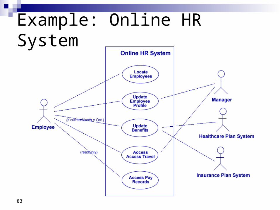
Example: Online HR System

84
Use-Case Diagram ExampleUse-Case Diagram ExampleUse-Case Diagram ExampleUse-Case Diagram Example
student
register for courseregister for course
works with course
lecturer
adm
lab
instructor
make/edit course
register for examregister for exam
register as studentregister as student
System Boundary

Use Case – Exercise
Indian Railways provides for advance reservation on all long-distance travel. The passenger seeking reservation of berth or seats should purchase the tickets from Railway Reservation Offices or Authorised Travel Agency only. To make an advance booking, the passenger is expected to fill in a prescribed application form and submit it to the reservation counter with the appropriate amount. Advanced Reservations are made up to 60 days in advance for all trains, for all classes exclusive of the day of departure of trains. An individual can book only up to six passengers on one requisition form provided all passengers are for the same destination and for the same train.
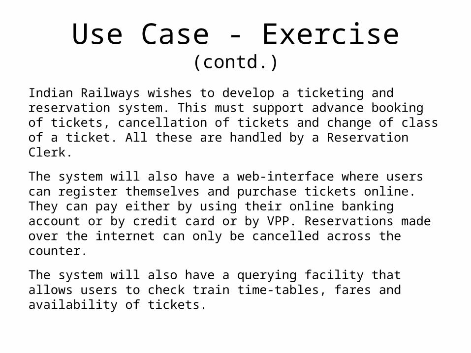
Use Case - Exercise (contd.)
Indian Railways wishes to develop a ticketing and reservation system. This must support advance booking of tickets, cancellation of tickets and change of class of a ticket. All these are handled by a Reservation Clerk.
The system will also have a web-interface where users can register themselves and purchase tickets online. They can pay either by using their online banking account or by credit card or by VPP. Reservations made over the internet can only be cancelled across the counter.
The system will also have a querying facility that allows users to check train time-tables, fares and availability of tickets.

Use Case - Example (contd.)
Make Reservation
CancelReservation
Modify Class
Print Ticket
Use Cases:
Query Timetable
Check Fare
Register as Member
88
Use Case Relationships

89
Four Use Case Relationships
Uses Includes Generalizes Extends

90
Use-Case Diagram

91
Online HR System: Use Case Relationships

92
The <<extends>> Relationship <<extends>> relationships
represent exceptional or invoked cases.
The exceptional event flows are factored out of the main event flow for clarity.
Use cases representing exceptional flows can extend more than one use case.
The direction of a <<extends>> relationship is to the extended use case
Passenger
BookFlightByPhone
BookFlightByOperator
<<extends>>
93
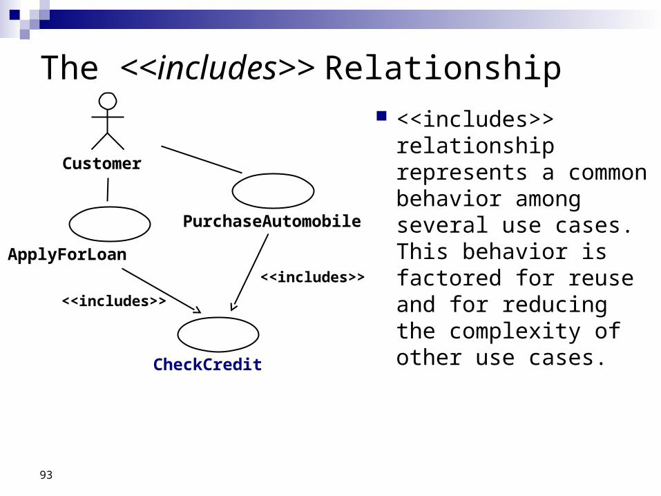
The <<includes>> Relationship <<includes>>
relationship represents a common behavior among several use cases. This behavior is factored for reuse and for reducing the complexity of other use cases.
Customer
ApplyForLoan
PurchaseAutomobile
<<includes>>
CheckCredit
<<includes>>
94
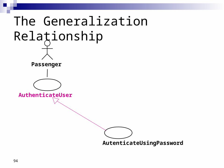
The Generalization Relationship
Passenger
AuthenticateUser
AutenticateUsingPassword

95
Finding Use Cases: Useful Questions
What are the tasks of each actor? Will the actor create, store, change, remove, or read
information in the system? What use case will create, store, change, remove, or
read information in the system? Will the actor need to inform the system about sudden,
external changes?

96
Finding Use Cases: Useful Questions
Does the actor need to be informed about certain occurrences in the system?
Does the system supply the business with the correct behavior?
What use cases will support and maintain the system? Can all functional requirements be performed by the use
cases?

97
Scenarios “A narrative description of what people do and
experience as they try to make use of computer systems and applications” [M. Carrol, Scenario-based Design, Wiley, 1995]
A concrete, focused, informal description of a single feature of the system used by a single actor.
Scenarios can have many different uses during the software lifecycle

98
What are Scenarios ?
A scenario is an instance of a use case It is one flow through a use case
Each use case will have a web of scenariosPrimary scenarios (happy day scenarios)
Normal flow - the way the system should work
Secondary scenarios Exceptions to the primary scenario

99
Use Case Flow of Events

100
How do we find scenarios? Don’t expect the client to be verbal if the system
does not exist (greenfield engineering) Don’t wait for information even if the system exists Engage in a dialectic approach (evolutionary,
incremental)You help the client to formulate the requirementsThe client helps you to understand the requirementsThe requirements evolve while the scenarios are being
developed

101
Heuristics for finding Scenarios Ask yourself or the client the following questions:
What are the primary tasks that the system needs to perform? What data will the actor create, store, change, remove or add in
the system? What external changes does the system need to know about? What changes or events will the actor of the system need to be
informed about?
Insist on task observation if the system already exists (interface engineering or reengineering)
Ask to speak to the end user, not just to the software contractor Expect resistance and try to overcome it

102
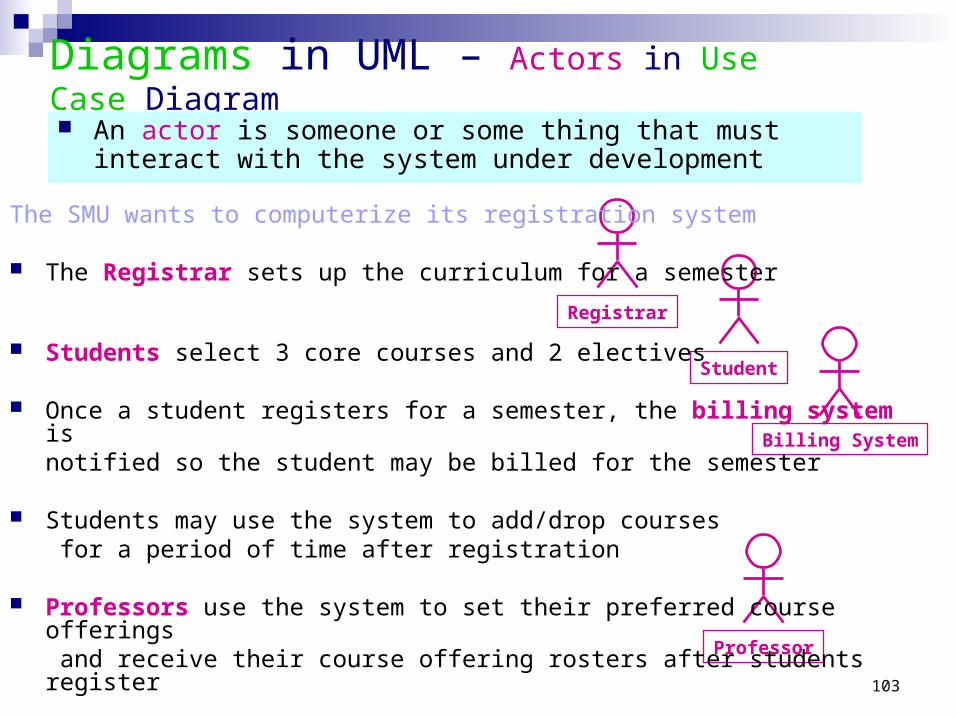
Exercise: Use Case Diagram in UML
The SMU wants to computerize its registration system
The Registrar sets up the curriculum for a semester
Students select 3 core courses and 2 electives
Once a student registers for a semester, the billing system is notified so the student may be billed for the semester
Students may use the system to add/drop courses for a period of time after registration
Professors use the system to set their preferred course offeringsand receive their course offering rosters after students register
Users of the registration system are assigned passwords which are used at logon validation
103
Diagrams in UML – Actors in Use Case Diagram
Student
Registrar
Professor
Billing System
An actor is someone or some thing that must interact with the system under development
The SMU wants to computerize its registration system
The Registrar sets up the curriculum for a semester
Students select 3 core courses and 2 electives
Once a student registers for a semester, the billing system is notified so the student may be billed for the semester
Students may use the system to add/drop courses for a period of time after registration
Professors use the system to set their preferred course offerings and receive their course offering rosters after students register
Users of the registration system are assigned passwords which are used at logon validation

104
Diagrams in UML – Use Cases in Use Case Diagram
Student
Registrar
Professor
Billing System
The SMU wants to computerize its registration system
The Registrar sets up the curriculum for a semester
Students select 3 core courses and 2 electives
Once a student registers for a semester, the billing system is notified so the student may be billed for the semester
Students may use the system to add/drop courses for a period of time after registration
Professors use the system to set their preferred course offerings and receive their course offering rosters after students register
Users of the registration system are assigned passwords which are used at logon validation
A use case is a sequence of interactions between an actor and the system
Maintain Curriculum
Request Course Roster
Register for Courses
Set Course Offerings
105
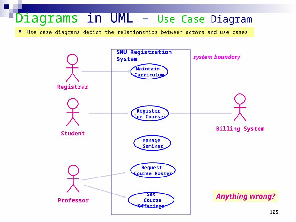
Diagrams in UML – Use Case Diagram
Student
Registrar
Professor
Billing System
Maintain Curriculum
Request Course Roster
Register for Courses
Set Course Offerings
Use case diagrams depict the relationships between actors and use cases
system boundary
Manage Seminar
Anything wrong?
SMU Registration System

106
Diagrams in UML - Uses and Extends in Use Case Diagram
A uses relationship shows behavior common to one or more use cases
An extends relationship shows optional/exceptional behavior
Register for courses
<<uses>>
Logon validation<<uses>>
Maintain curriculum
Register for Distance Learning courses
<<extends>>
Create course
<<uses>>
Maintain Schedule
<<uses>>

107
Diagrams in UML – Flow of Events for each use case:
Typical contents:How the use case starts and endsNormal flow of events (focus on the normal first!)
Alternate/Exceptional flow of events
This use case begins after the Registrar logs onto the Registration System with a valid password.
The registrar fills in the course form with the appropriate semester and course related info.
The Registrar requests the system to process the course form.
The system creates a new course, and this use case ends
Flow of Events for Creating a Course Registrar Create Course

108
Use Cases
Scenarios describe a single path, or a particular sequence E.g., Use Case: Order Goods
Scenario 1: all goes well Scenario 2: insufficient funds Scenario 3: out of stock
System test cases: Generate a test script for each scenario (flow of events). Obtain initial state from preconditions. Test success against post conditions.
When to Use Use Cases Fowler’s View: do use cases first before object modeling
Capture the simple, normal use-case first For every step ask “What could go wrong?” and how it might work out
differently Plot all variations as extensions of the given use case
Another view: do object modeling first, then use cases Another: iterate model - use case - model - use case ...
What did we do?

109
Organizing Use Cases
• Generalization, Extend, Include/Use, packages
Track ordergeneralization
Validate user
Retinal scan
Check password
Place rush orderPlace order
Extension points:set priority
extension
inclusion
extension point
<<extend>>
(set priority)
<<include>>
<<include>>
• Track Order - Obtain and verify the order number; For each part in the order, query its status, then report back to the user.
• Place Order - Collect the user’s order items. (set priority). Submit the order for processing.
common to multiple use cases;Often no actor may be associated with a ‘used’ use case
UML 1.3: Replaces <<uses>> relationship with Generalization and <<include>> dependency (http://www.jeckle.de/files/viewfront.pdf)
does a bit more or deals with a special situation
extension use case
inclusion use case
child use case
base use case

110
A Use Case Template (http://www.bredemeyer.com/pdf_files/use_case.pdf)
Non-Functional (optional)List of NFRs that the use case must meetIssues List of issues that remain to be resolved
Use Case Identifier: e.g., “Withdraw money”; ref # = wm3; mod history = …
Actors List of actors involved in use case
Brief description Goal: E.g., “This use case lets a bank account owner withdraw money from an ATM machine”; Source: Bank doc 2.3
Preconditions What should be true before the use case can start.
Postconditions What should hold after the use case successfully completes.
Basic flow of events The happy/sunny day flow. The most common successful case.
Alt. flow of events /subflows Difference for the specific subflow
Exception flows Subflows may be divided into 1) normal, 2) successful alternate actions, and 3) exception/error flows.

111
A Use Case TemplateUse Case (id, ref#, mod history)
2. Reparing_Cellular_Network
History created 1/5/98 Derek Coleman, modified 5/5/98
Description (goal, source) Operator rectifies a report by changing parameters of a cell
Actors Operator (primary, Cellular network, Field maintenance engineer)
Assumptions (successful use case termination condition)
Changes to network are always successful when applied to a network
Steps 1. Operator notified of network problem
2. Operator starts repair session
3. REPEAT
3.1 Operator runs network diagnosis application
3.2 Operator identifies cells to be changes and their new parameter values
3.3 IN PARALLEL
3.3.1 Maintenance engineer tests network cells ||
3.3.2 Maintenance engineer sends fault reports
UNTIL no more reports of problem
4. Operator closes repair session
Variations (optional) #1. System may detect fault and notify operator or
Field maintenance engineer may report fault to Operator
Non-Functional (optional) Performance Mean: time to repair network fault must be less than 3 hours
Issues (that remain to be resolved)
What are the modes of communication between field maintenance engineer and operator
(http://www.bredemeyer.com/pdf_files/use_case.pdf)
Use Case Extension Repair_may_fail extends 2. Reparing_Cellular_Network
Description Deals with assumption that network changes can never fail
Steps #3.3. if the changes to network fail then the network is rolled back to its previous state
Issues How are failures detected? Are roll backs automatic or is Operator intervention required?

112
Class Diagrams &
Object Diagrams

113
Essentials of UML Class Diagrams
The main symbols shown on class diagrams are:
• Classes- represent the types of data themselves
• Associations- represent linkages between instances of classes
• Attributes- are simple data found in classes and their instances
• Operations- represent the functions performed by the classes and their
instances
• Generalizations- group classes into inheritance hierarchies

114
Classes
A class is simply represented as a box with the name of the class inside
• The diagram may also show the attributes and operations
• The complete signature of an operation is:
operationName(parameterName: parameterType …): returnType
Rectangle
height: intwidth: int
getArea(): intresize(int,int)
Rectangle
heightwidth
getArearesize
Rectangle
heightwidth
Rectangle
getArearesize
Rectangle

115
Associations and Multiplicity
An association is used to show how two classes are related to each other
• Symbols indicating multiplicity are shown at each end of the association
0,3..8 ******
Employee
*
* *****1..*
*0..1
Secretary
Office
Person
Company
Employee Company
Manager
BoardOfDirectors
BoardOfDirectors

116
Labelling associations
• Each association can be labelled, to make explicit the nature of the association
*
supervisor
*****1..*
* worksFor
*allocatedTo0..1
boardMember
0,3..8 ******
Employee
Secretary
Office
Person
Company
Employee Company
Manager
BoardOfDirectors
BoardOfDirectors

117
Analyzing and validating associations
• One-to-one
—For each company, there is exactly one board of directors
—A board is the board of only one company
—A company must always have a board
—A board must always be of some company
Company BoardOfDirectors

118
Analyzing and validating associations
• Many-to-many
—A secretary can work for many managers
—A manager can have many secretaries
—Secretaries can work in pools
—Managers can have a group of secretaries
—Some managers might have zero secretaries.
—Is it possible for a secretary to have, perhaps temporarily, zero managers?
*
supervisor
*****1..*Secretary Manager

119
Analyzing and validating associations
Avoid unnecessary one-to-one associations
Avoid this do this
Person
nameaddressemailbirthdate
Person
name
PersonInfo
addressemailbirthdate

120
A more complex example
• A booking is always for exactly one passenger
—no booking with zero passengers
—a booking could never involve more than one passenger.
• A Passenger can have any number of Bookings
—a passenger could have no bookings at all
—a passenger could have more than one booking
************Passenger SpecificFlightBooking

121
Association classes
• Sometimes, an attribute that concerns two associated classes cannot be placed in either of the classes
• The following are equivalent
Registration
grade
Student CourseSection* ******
Registration
grade
Student CourseSection* *

122
Reflexive associations
• It is possible for an association to connect a class to itself
Course *isMutuallyExclusiveWith
*
*
prerequisite
successor *
123
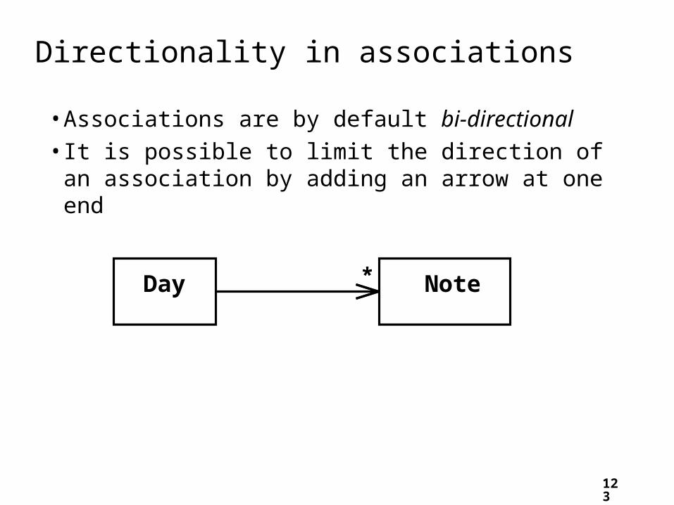
Directionality in associations
• Associations are by default bi-directional
• It is possible to limit the direction of an association by adding an arrow at one end
** NoteDay

124
Generalization
Specializing a superclass into two or more subclasses
• The discriminator is a label that describes the criteria used in the specialization
Animal Animal
habitat typeOfFood
HerbivoreCarnivoreLandAnimalAquaticAnimal

125
Avoiding unnecessary generalizations
RockRecordingBluesRecordingClassicalRecordingJazzRecordingMusicVideo
VideoRecoding AudioRecording
Recording
rockbluesclassicaljazzmusic video
video audio
RecordingCategory*subcategorydescription
Recording *hasCategory
subcategory subcategorysubcategorysubcategorysubcategory
:RecordingCategory :RecordingCategory
:RecordingCategory :RecordingCategory :RecordingCategory :RecordingCategory:RecordingCategory
9th Symphony
:Recording
Let it be
:Recording
The BeatlesBeethoven
titleartist
Inappropriate hierarchy ofclasses, which should beinstances
Improved class diagram,with its correspondinginstance diagram
126
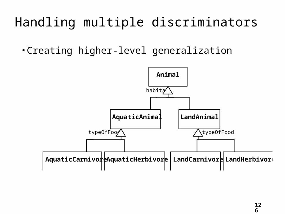
Handling multiple discriminators
Animal
habitat
LandAnimalAquaticAnimal
AquaticCarnivore AquaticHerbivore LandCarnivore LandHerbivore
typeOfFood typeOfFood
• Creating higher-level generalization

127
• Using multiple inheritance
Handling multiple discriminators
Animal
habitat typeOfFood
HerbivoreCarnivoreLandAnimalAquaticAnimal
AquaticCarnivore AquaticHerbivore LandCarnivore LandHerbivore

128
Avoiding having instances change class
Student
attendance
PartTimeStudentFullTimeStudent
• An instance should never need to change class

129
Object Diagrams
• A link is an instance of an association
—In the same way that we say an object is an instance of a class
Carla:Employee
Ali:Employee
Wayne:EmployeeOOCorp:Company OOCorp's Board:
UML inc's BoardUML inc:Company
Pat:Employee
Terry:Employee

130
Associations versus generalizations in object diagrams
• Associations describe the relationships that will exist between instances at run time.
—When you show an object diagram generated from a class diagram, there will be instances of both classes joined by an association
• Generalizations describe relationships between classes in class diagrams.
—They do not appear in object diagrams at all.
—An instance of any class should also be considered to be an instance of each of that class’s superclasses

131
More Advanced Features: Aggregation
• Aggregations are special associations that represent ‘part-whole’ relationships.
—The ‘whole’ side is often called the assembly or the aggregate
—This symbol is a shorthand notation association named isPartOf
****
****** Region
VehiclePart
Country
Vehicle
132
When to use an aggregation
As a general rule, you can mark an association as an aggregation if the following are true:
• You can state that
—the parts ‘are part of’ the aggregate
—or the aggregate ‘is composed of’ the parts
• When something owns or controls the aggregate, then they also own or control the parts

133
• A composition is a strong kind of aggregation
—if the aggregate is destroyed, then the parts are destroyed as well
• Two alternatives for addresses
Composition
***** RoomBuilding
EmployeeEmployeeaddress: Address
AddressstreetmunicipalityregioncountrypostalCode

134
Aggregation hierarchy
* *
*
WheelTransmissionEngineFrame
DoorBodyPanelChassis
Vehicle
135
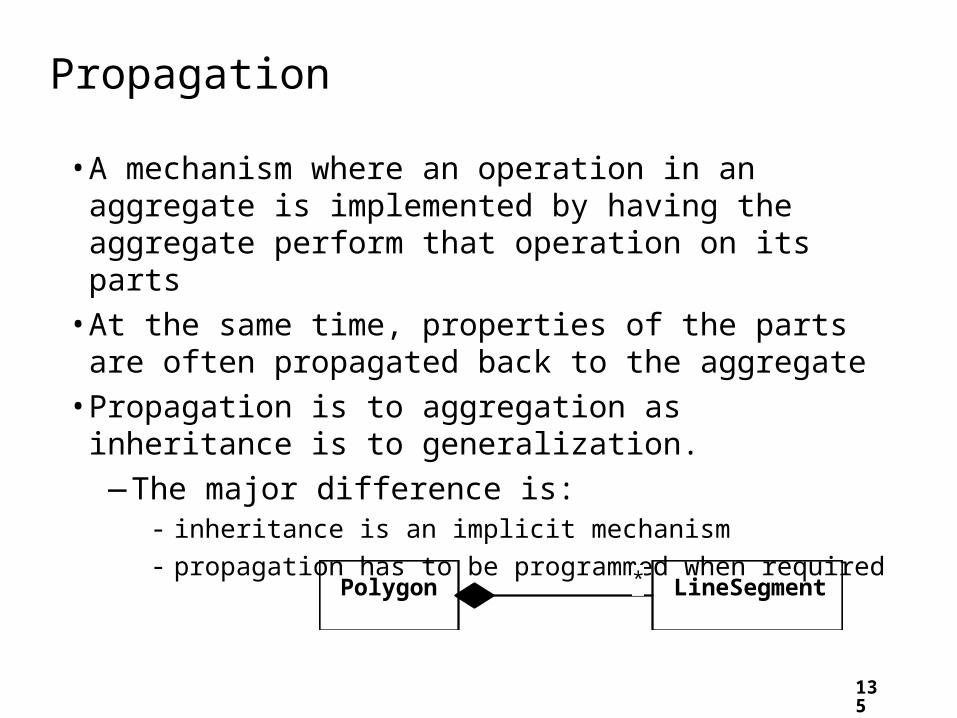
Propagation
• A mechanism where an operation in an aggregate is implemented by having the aggregate perform that operation on its parts
• At the same time, properties of the parts are often propagated back to the aggregate
• Propagation is to aggregation as inheritance is to generalization.
—The major difference is:- inheritance is an implicit mechanism
- propagation has to be programmed when required ****** LineSegmentPolygon

136
Interfaces
An interface describes a portion of the visible behaviour of a set of objects.
• An interface is similar to a class, except it lacks instance variables and implemented methods
«interface»Cashier
withdrawdeposit
Machine
ATMEmployee
Person Machine
ATMEmployee
Person
Cashier Cashier

137
Notes and descriptive text
• Descriptive text and other diagrams
—Embed your diagrams in a larger document
—Text can explain aspects of the system using any notation you like
—Highlight and expand on important features, and give rationale
• Notes:
—A note is a small block of text embedded in a UML diagram
—It acts like a comment in a programming language
138
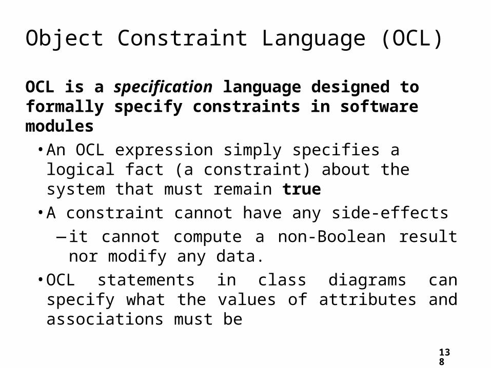
Object Constraint Language (OCL)
OCL is a specification language designed to formally specify constraints in software modules
• An OCL expression simply specifies a logical fact (a constraint) about the system that must remain true
• A constraint cannot have any side-effects
—it cannot compute a non-Boolean result nor modify any data.
• OCL statements in class diagrams can specify what the values of attributes and associations must be

139
OCL statements
OCL statements can be built from:
• References to role names, association names, attributes and the results of operations
• The logical values true and false
• Logical operators such as and, or, =, >, < or <> (not equals)
• String values such as: ‘a string’
• Integers and real numbers
• Arithmetic operations *, /, +, -

140
An example: constraints on Polygons
LinearShape
startPoint: Point1..*
edgeLineSegment
Path Line Polygon
RegularPolygon
endPoint: Point
{startPoint <> endPoint}
{ordered}
{edge->size=1}
{edge->forAll(e1,e2 | e1.length = e2.length)}
{edge->forAll(e1,e2 | e1 <> e2
implies e1.startPoint <> e2.startpoint and e1.endPoint <> e2.endpoint)}
length : int
length{length = edge.length->sum}
{edge->first.startPoint = edge->last.endPoint}
a LinearShape is any shape that can be constructed of line segments (in contrast with shapes that contain curves).
141
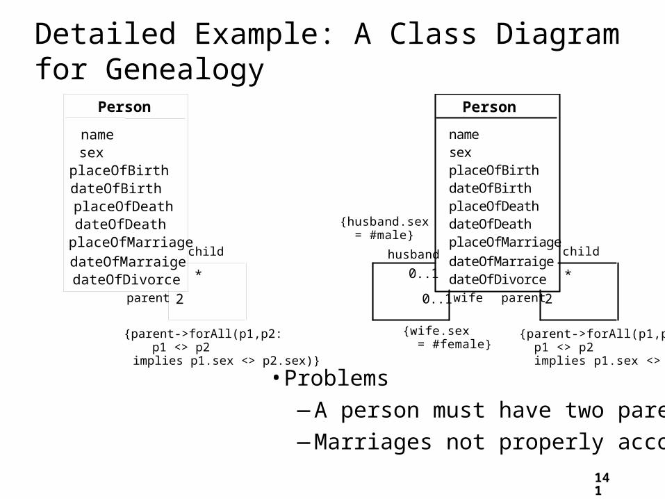
Detailed Example: A Class Diagram for Genealogy
• Problems
—A person must have two parents
—Marriages not properly accounted for
2
child
Person
name
placeOfBirthdateOfBirthplaceOfDeathdateOfDeathplaceOfMarriage
dateOfMarraigedateOfDivorce *
parent
0..1
0..1 wife
husband
{husband.sex = #male}
{wife.sex = #female}
{parent->forAll(p1,p2: p1 <> p2 implies p1.sex <> p2.sex)}
sex
2
child
Person
name
placeOfBirthdateOfBirthplaceOfDeathdateOfDeathplaceOfMarriage
dateOfMarraigedateOfDivorce *
parent
{parent->forAll(p1,p2: p1 <> p2 implies p1.sex <> p2.sex)}
sex

142
Genealogy example: Possible solutions
Person
nameplaceOfBirthdateOfBirthplaceOfDeathdateOfDeath
Union
placeOfMarriagedateOfMarriagedateOfDivorce
parents
0..1
child
*
child*** malePartner* 0..1child
**
femalePartner 0..1
Woman Man
Person
name
placeOfBirthdateOfBirthplaceOfDeathdateOfDeath
Union
placeOfMarriagedateOfMarriagedateOfDivorce
parents
0..1
child
*
****
*
partner 0..2
sex
{partner->forAll(p1,p2 | p1 <> p2
implies p1.sex <> p2.sex)}

143
The Process of Developing Class Diagrams
You can create UML models at different stages and with different purposes and levels of details
• Exploratory domain model:
—Developed in domain analysis to learn about the domain
• System domain model:
—Models aspects of the domain represented by the system
• System model:
—Includes also classes used to build the user interface and system architecture
144
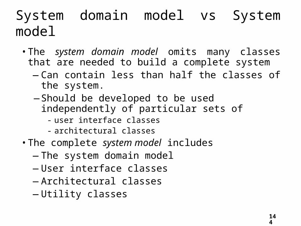
System domain model vs System model
• The system domain model omits many classes that are needed to build a complete system
—Can contain less than half the classes of the system.—Should be developed to be used independently of
particular sets of- user interface classes - architectural classes
• The complete system model includes —The system domain model—User interface classes—Architectural classes—Utility classes

145
Suggested sequence of activities
• Identify a first set of candidate classes • Add associations and attributes • Find generalizations • List the main responsibilities of each class • Decide on specific operations • Iterate over the entire process until the model is
satisfactory—Add or delete classes, associations, attributes,
generalizations, responsibilities or operations—Identify interfaces—Apply design patterns
Don’t be too disorganized. Don’t be too rigid either.

146
Identifying classes
• When developing a domain model you tend to discover classes
• When you work on the user interface or the system architecture, you tend to invent classes
—Needed to solve a particular design problem
—(Inventing may also occur when creating a domain model)
• Reuse should always be a concern
—Frameworks
—System extensions
—Similar systems
147
A simple technique for discovering domain classes
• Look at a source material such as a description of requirements
• Extract the nouns and noun phrases
• Eliminate nouns that:
—are redundant
—represent instances
—are vague or highly general
—not needed in the application
• Pay attention to classes in a domain model that represent types of users or other actors

148
Exercise: Airline Reservation System
Ootumlia Airlines runs sightseeing flights from Java Valley, the capital of Ootumlia. The reservation system keeps track of passengers who will be flying in specific seats on various flights, as well as people who will form the crew. For the creaw, the system needs to track what everyone does, and who supervises whom. Ootumilia Airlines runs several daily numbered flights on a regular schedule. Ootumlia Airline expects to expand in the future, therefore the system needs to be flexible; in particular, it will be adding a frequent-flier plan.
•List the nouns and noun phrases that might end up being classes in a system domain model. For those nouns that should not become classes, explain why not

149
Identifying associations and attributes
• Start with classes you think are most central and important
• Decide on the clear and obvious data it must contain and its relationships to other classes.
• Work outwards towards the classes that are less important.
• Avoid adding many associations and attributes to a class
—A system is simpler if it manipulates less information

150
Tips about identifying and specifying valid associations
• An association should exist if a class - possesses
- controls
- is connected to
- is related to
- is a part of
- has as parts
- is a member of, or
- has as members
some other class in your model
• Specify the multiplicity at both ends
• Label it clearly.

151
Actions versus associations
• A common mistake is to represent actions as if they were associations
*
LibraryPatron
borrow Loan
borrowedDatedueDatereturnedDate
Bad, due to the use of associations that are actions
****
*
return
CollectionItem
*
*
LibraryPatron
CollectionItem
*
*
Better: The borrow operation creates a Loan,and the return operation sets the
returnedDate attribute

152
Identifying attributes
• Look for information that must be maintained about each class
• Several nouns rejected as classes, may now become attributes
• An attribute should generally contain a simple value
—E.g. string, number

153
Tips about identifying and specifying valid attributes
• It is not good to have many duplicate attributes
• If a subset of a class’s attributes form a coherent group, then create a distinct class containing these attributes
****
*
Person
nameaddresses
addressesPerson
namestreet1 municipality1 provOrState1 country1 postalCode1street2 municipality2 provOrState2 country2 postalCode2
Person
name
Address
street municipality provOrState country postalcode type
Bad due to a plural attribute
Bad due to too many attributes, and inability to add more addresses
Good solution. The type indicates whether it is a home address, business address etc.

154
Exercise: For the Airline Reservation System, add an initial set of attributes and associations to the classes you identified. Add and delete classes as necessary.
*
supervisor
RegularFlight
timeflightNumber
*
******
Passenger
******
******
******
SpecificFlight
date
nameemployeeNumber
Employee
jobFunction
Booking
seatNumber
namenumber

155
Identifying generalizations and interfaces
• There are two ways to identify generalizations: —bottom-up
- Group together similar classes creating a new superclass
—top-down- Look for more general classes first, specialize them if needed
• Create an interface, instead of a superclass if —The classes are very dissimilar except for having a few
operations in common —One or more of the classes already have their own
superclasses —Different implementations of the same class might be
available

156
Exercise: For Airline Reservation System, add any obvious generalizations, making whatever other changes become necessary.
*
supervisor
RegularFlight
timeflightNumber
*
******
PassengerRole
******
******
******
SpecificFlight
date
Person
nameidNumber
0..20..20..20..20..20..2
EmployeeRole
jobFunction
Booking
seatNumber
PersonRole

157
Allocating responsibilities to classes
A responsibility is something that the system is required to do. • Each functional requirement must be attributed to one of the classes
—All the responsibilities of a given class should be clearly related.—If a class has too many responsibilities, consider splitting it into
distinct classes —If a class has no responsibilities attached to it, then it is probably
useless —When a responsibility cannot be attributed to any of the existing
classes, then a new class should be created
• To determine responsibilities —Perform use case analysis —Look for verbs and nouns describing actions in the system description

158
Categories of responsibilities
• Setting and getting the values of attributes
• Creating and initializing new instances
• Loading to and saving from persistent storage
• Destroying instances
• Adding and deleting links of associations
• Copying, converting, transforming, transmitting or outputting
• Computing numerical results
• Navigating and searching
• Other specialized work

159
—Creating a new regular flight
—Searching for a flight
—Modifying attributes of a flight
—Creating a specific flight
—Booking a passenger
—Canceling a booking
*
supervisor
RegularFlight
timeflightNumber
*
******
PassengerRole
******
******
******
SpecificFlight
date
******
******Person
nameidNumber
0..20..20..20..20..20..2
EmployeeRole
jobFunction
Booking
seatNumber
PersonRoleAirline
Exercise: For Airline Reservation System, allocate the responsibilities to a class and discuss your reasoning for allocation. Finally update the class diagram as necessary.
160
Prototyping a class diagram on paper-CRC
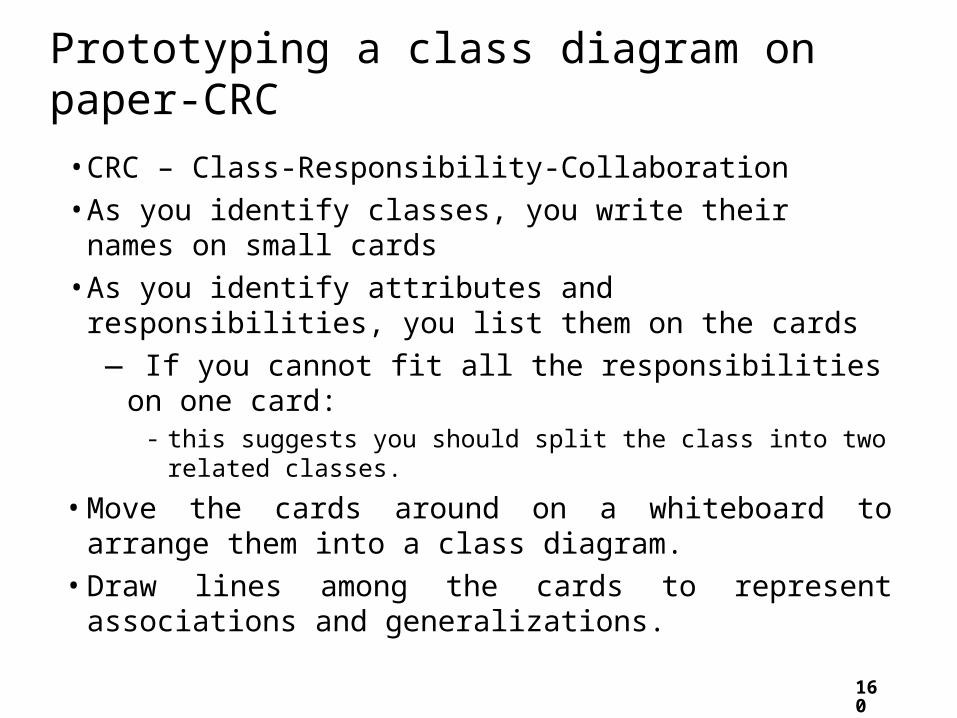
• CRC – Class-Responsibility-Collaboration
• As you identify classes, you write their names on small cards
• As you identify attributes and responsibilities, you list them on the cards
— If you cannot fit all the responsibilities on one card:- this suggests you should split the class into two related classes.
• Move the cards around on a whiteboard to arrange them into a class diagram.
• Draw lines among the cards to represent associations and generalizations.

161
Identifying operations
Operations are needed to realize the responsibilities of each class
• There may be several operations per responsibility
• The main operations that implement a responsibility are normally declared public
• Other methods that collaborate to perform the responsibility must be as private as possible
162
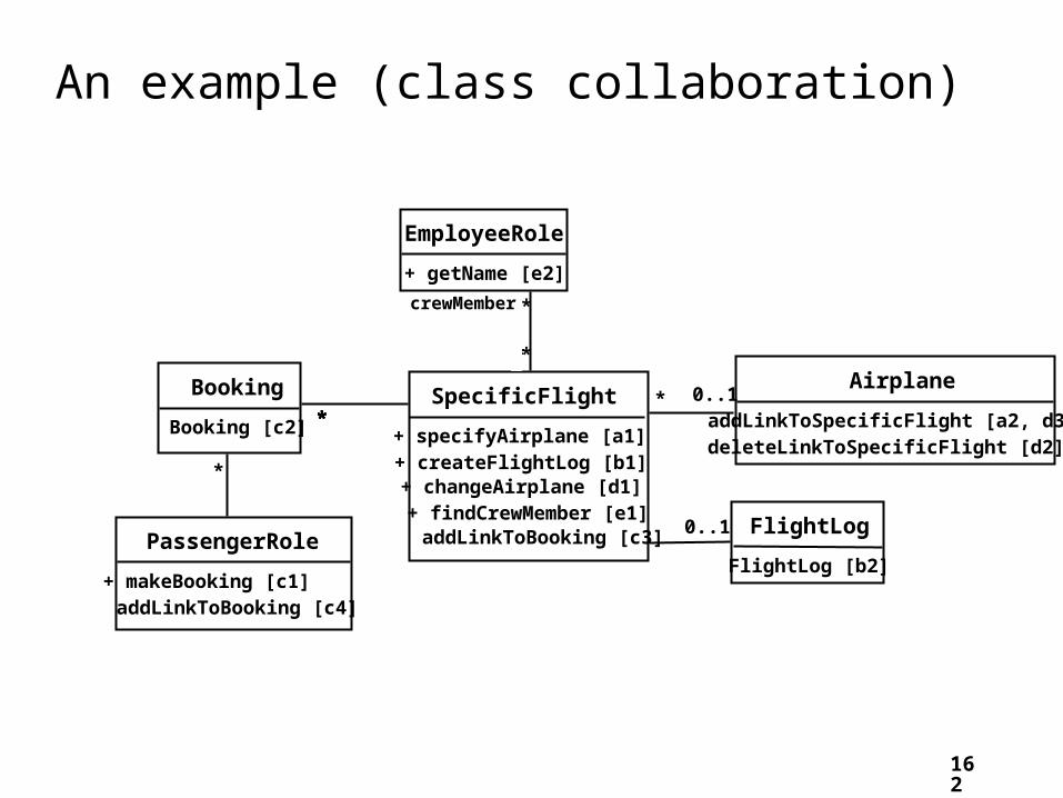
An example (class collaboration)
Airplane
addLinkToSpecificFlight [a2, d3]deleteLinkToSpecificFlight [d2]
SpecificFlight
+ specifyAirplane [a1]+ createFlightLog [b1]
+ makeBooking [c1]
+ changeAirplane [d1]+ findCrewMember [e1]
EmployeeRole
+ getName [e2]
FlightLog
FlightLog [b2]
Booking
Booking [c2]
PassengerRole
addLinkToBooking [c4]
*
******
0..1
*
*
******
crewMember
0..1
addLinkToBooking [c3]

163
Class collaboration ‘a’
Making a bi-directional link between two existing objects; e.g. adding a link between an instance of
SpecificFlight and an instance of Airplane. 1. (public) The instance of SpecificFlight
— makes a one-directional link to the instance of Airplane
— then calls operation 2.2. (non-public) The instance of Airplane
— makes a one-directional link back to the instance of SpecificFlight
Airplane
addLinkToSpecificFlight [a2, d3]
SpecificFlight
+ specifyAirplane [a1]
* 0..1

164
Class collaboration ‘b’
Creating an object and linking it to an existing objecte.g. creating a FlightLog, and linking it to a
SpecificFlight. 1. (public) The instance of SpecificFlight
—calls the constructor of FlightLog (operation 2)—then makes a one-directional link to the new
instance of FlightLog.2. (non-public) Class FlightLog’s constructor
—makes a one-directional link back to the instance of SpecificFlight.
SpecificFlight
+ createFlightLog [b1]
FlightLog
FlightLog [b2]
0..10..10..10..10..10..1

165
Class collaboration ‘c’Creating an association class, given two existing objectse.g. creating an instance of Booking, which will link a
SpecificFlight to a PassengerRole.1. (public) The instance of PassengerRole
— calls the constructor of Booking (operation 2).2. (non-public) Class Booking’s constructor, among its other actions
— makes a one-directional link back to the instance of PassengerRole
— makes a one-directional link to the instance of SpecificFlight
— calls operations 3 and 4.3. (non-public) The instance of SpecificFlight
— makes a one-directional link to the instance of Booking.4. (non-public) The instance of PassengerRole
— makes a one-directional link to the instance of Booking.
SpecificFlight+ makeBooking [c1]
Booking
Booking [c2]
PassengerRole
addLinkToBooking [c4]* ****** addLinkToBooking [c3]

166
Class collaboration ‘d’
Changing the destination of a linke.g. changing the Airplane of to a SpecificFlight,
from airplane1 to airplane2 1. (public) The instance of SpecificFlight
—deletes the link to airplane1—makes a one-directional link to airplane2—calls operation 2— then calls operation 3.
2. (non-public) airplane1—deletes its one-directional link to the instance of SpecificFlight.
3. (non-public) airplane2—makes a one-directional link to the instance of SpecificFlight.
Airplane
addLinkToSpecificFlight [a2, d3]deleteLinkToSpecificFlight [d2]
SpecificFlight
+ changeAirplane [d1]
* 0..1

167
Class collaboration ‘e’
Searching for an associated instance
e.g. searching for a crew member associated with a SpecificFlight that has a certain name.
1. (public) The instance of SpecificFlight
— creates an Iterator over all the crewMember links of the SpecificFlight\
— for each of them call operation 2, until it finds a match.
2. (may be public) The instance of EmployeeRole returns its name.
SpecificFlight
+ findCrewMember [e1]
EmployeeRole
+ getName [e2]
* *crewMember

168
Implementing Class Diagrams in Java• Attributes are implemented as instance variables
• Generalizations are implemented using extends
• Interfaces are implemented using implements• Associations are normally implemented using instance variables
• Divide each two-way association into two one-way associations—so each associated class has an instance variable.
• For a one-way association where the multiplicity at the other end is ‘one’ or ‘optional’
—declare a variable of that class (a reference)
• For a one-way association where the multiplicity at the other end is ‘many’:
—use a collection class implementing List, such as Vector
169
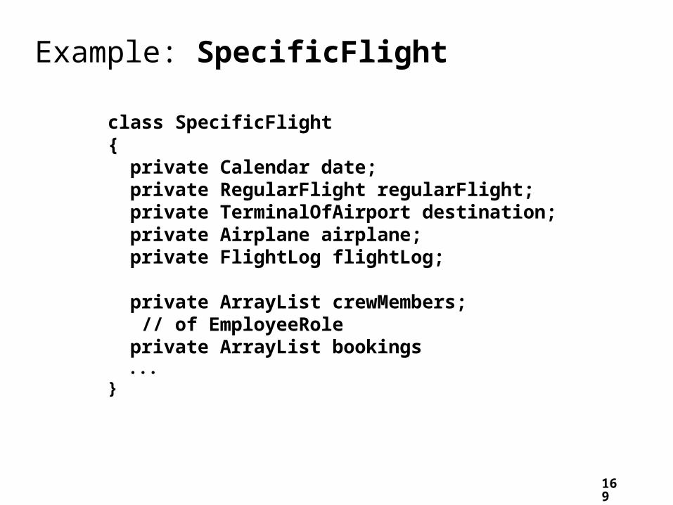
Example: SpecificFlight
class SpecificFlight{ private Calendar date; private RegularFlight regularFlight; private TerminalOfAirport destination; private Airplane airplane; private FlightLog flightLog; private ArrayList crewMembers; // of EmployeeRole private ArrayList bookings ...}

170
Example: SpecificFlight
// Constructor that should only be called from // addSpecificFlight SpecificFlight( Calendar aDate, RegularFlight aRegularFlight) { date = aDate; regularFlight = aRegularFlight; }

171
Example: RegularFlightclass RegularFlight{ private ArrayList specificFlights; ... // Method that has primary // responsibility
public void addSpecificFlight( Calendar aDate) { SpecificFlight newSpecificFlight; newSpecificFlight = new SpecificFlight(aDate, this); specificFlights.add(newSpecificFlight); } ...}

Exercise:
A binary tree either is empty (no nodes), or has a root node, a left tree, and a right binary. Is the following a good model of a binary tree. If not, present a correct UML model.