Embed Size (px)
Citation preview

UML (Unified Modeling Language)
UML Outline
Software Institute of
Nanjing University 2009

Instructor
刘嘉 (Liu Jia)
Email : [email protected]
ext : 509
Office : 705
2009.3 by iKirly ( Software Institute of Nanjing University )
2
References
[1] The Unified Modeling Language User Guide SECOND EDITION by Grady Booch, Jim Rumbaugh, Ivar Jacobson
Publisher : Addison Wesley
[2] The Unified Modeling Language Reference Manual SECOND EDITION by Grady Booch, Jim Rumbaugh, Ivar Jacobson
Publisher : Addison Wesley
2009.3 by iKirly ( Software Institute of Nanjing University )
3
References(cont’)
[3] UML Distilled: A Brief Guide to the Standard Object Modeling Language, Third Edition
By Martin Fowler
Publisher : Addison Wesley Professional
[4] Applying UML and Patterns: An Introduction to Object-Oriented Analysis and Design and Iterative Development, Third Edition
By Craig Larman
Publisher : Addison Wesley Professional
2009.3 by iKirly ( Software Institute of Nanjing University )
4

What Is the UML
The Unified Modeling Language (UML)
is a family of graphical notations, backed by single meta-model, that help in describing and designing software systems, particularly software systems built using the object-oriented (OO) style.
2009.3 by iKirly ( Software Institute of Nanjing University )
5

The History of UML
2009.3 by iKirly ( Software Institute of Nanjing University )
6

The History of UML (cont’)
2009.3 by iKirly ( Software Institute of Nanjing University )
7

UML Diagrams
Six structure diagrams, Three behavior diagrams, Four interaction diagrams, (13)
Structure Diagrams:
• Class Diagram *
• Component Diagram
• Composite Structure Diagram
• Deployment Diagram
• Object Diagram
• Package Diagram
2009.3 by iKirly ( Software Institute of Nanjing University )
8

UML Diagrams(cont’)
Behavior Diagrams:
• Use Case Diagram *
• Activity Diagram
• State machine Diagram
• Interaction Diagrams:
• Sequence Diagram *
• Communication Diagram
• Interactive overview Diagram
• Timing Diagram
Find Out More : UML booklet 2.0
2009.3 by iKirly ( Software Institute of Nanjing University )
9

What Is Legal UML?
Legal UML is what is defined as well formed in the specification.
For most people, the UML has descriptive rules.
It's more important to have a good design for your system, and I would rather have a good design in illegal UML than a legal but poor design.
2009.3 by iKirly ( Software Institute of Nanjing University )
10

The Meaning of UML
No formal definition exists of how the UML maps to any particular programming language.
You cannot look at a UML diagram and say exactly what the equivalent code would look like.
However, you can get a rough idea of what the code would look like. In practice, that's enough to be useful.
2009.3 by iKirly ( Software Institute of Nanjing University )
11

UML Is Not Enough
UML provides quite a considerable body of various diagrams that help to define an application
It's by no means a complete list of all the useful diagrams that you might want to use.
In many places, different diagrams can be useful, and you shouldn't hesitate to use a non-UML diagram if no UML diagram suits your purpose.
2009.3 by iKirly ( Software Institute of Nanjing University )
12

UML Is Not Enough(cont’)
2009.3 by iKirly ( Software Institute of Nanjing University )
13

Where to Start with the UML
Most people use a small subset of the UML and work with that.
You concentrate first on class diagrams and sequence diagrams and usecase diagrams. These are the most common and the most useful diagram types.
2009.3 by iKirly ( Software Institute of Nanjing University )
14
Part I Class Diagrams
A class diagram describes the types of objects in the system and the various kinds of static relationships that exist among them.
Class diagrams also show the properties and operations of a class and the constraints that apply
to the way objects are connected.
2009.3 by iKirly ( Software Institute of Nanjing University )
15

A simple class diagram
2009.3 by iKirly ( Software Institute of Nanjing University )
16

Classes
graphical representation
Three compartment : name, attributes, and operations
2009.3 by iKirly ( Software Institute of Nanjing University )
17

Attributes
The attribute :
visibility name: type multiplicity = default {property-string}
An example of this is:
name: String [1] = "Untitled" {readOnly}
Only the name is necessary
A general principle in the UML is that any information may be suppressed for a particular diagram.
2009.3 by iKirly ( Software Institute of Nanjing University )
18

Attributes(cont’)
This visibility marker indicates whether the attribute is public (+) or private (-);
The name of the attribute roughly corresponds to the name of a field in a programming language.
The type of the attribute indicates a restriction on what kind of object may be placed in the attribute. You can think of this as the type of a field in a programming language.
2009.3 by iKirly ( Software Institute of Nanjing University )
19

Attributes(cont’)
I'll explain multiplicity later
The default value is the value for a newly created object if the attribute isn't specified during creation.
The {property-string} allows you to indicate additional properties for the attribute
2009.3 by iKirly ( Software Institute of Nanjing University )
20

Operations
Operations are the actions that a class knows to carry out.
Operations most obviously correspond to the methods on a class.
Normally, you don't show those operations that simply manipulate properties, because they can usually be inferred.
2009.3 by iKirly ( Software Institute of Nanjing University )
21
Operations(cont’)
The full UML syntax for operations is:
visibility name (parameter-list) : return-type {property-string}
The Visibility is public (+) or private (-)
The name is a string
The parameter-list is the list of parameters for the operation
2009.3 by iKirly ( Software Institute of Nanjing University )
22
Operations(cont’)
The return-type is the type of the returned value, if there is one.
The property-string indicates property values that apply to the given operation.{query}
The parameters in the parameter list are notated in a similar way to attributes. The form is:
direction name: type = default value
2009.3 by iKirly ( Software Institute of Nanjing University )
23

Operations(cont’)
The name, type, and default value are the same as for attributes.
The direction indicates whether the parameter is input (in), output (out) or both (inout). If no direction is shown, it's assumed to be in.
An example operation on account might be:
+ balanceOn (date: Date) : Money
2009.3 by iKirly ( Software Institute of Nanjing University )
24
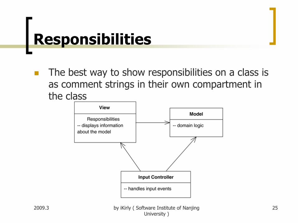
Responsibilities
The best way to show responsibilities on a class is as comment strings in their own compartment in the class
2009.3 by iKirly ( Software Institute of Nanjing University )
25

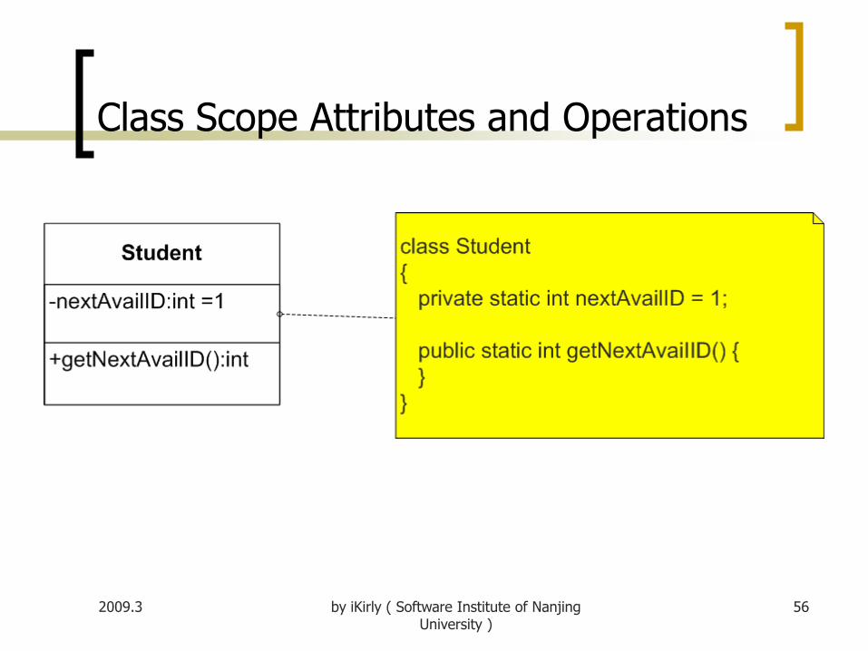
Static Operations and Attributes
The UML refers to an operation or an attribute that applies to a class rather than to an instance as static.
2009.3 by iKirly ( Software Institute of Nanjing University )
26

Notes and Comments
Notes are comments in the diagrams. Notes can stand on their own, or they can be linked with a dashed line to the elements they are commenting .
They can appear in any kind of diagram.
2009.3 by iKirly ( Software Institute of Nanjing University )
27
2009.3 by iKirly ( Software Institute of Nanjing University )
28
Relationships
Very few of classes stand alone. Instead, most of them collaborate with others in a number of ways.
not only must identify the things that form the vocabulary of the system
Must also model how these things stand in relation to one another

2009.3 by iKirly ( Software Institute of Nanjing University )
29
In object-oriented modeling, there are three kinds
of relationships that are especially important
dependencies, which represent using relationships among
classes;
generalizations, which link generalized classes to their
specializations;
associations, which represent structural relationships
among objects.
Each of these relationships provides a different
way of combining your abstractions
Relationships (cont’)

2009.3 by iKirly ( Software Institute of Nanjing University )
30
dependency
A dependency exists between two elements if
changes to the definition of one element (the
supplier) may cause changes to the other (the
client).

2009.3 by iKirly ( Software Institute of Nanjing University )
31
dependency (cont’)

2009.3 by iKirly ( Software Institute of Nanjing University )
32
With classes, dependencies exist for various reasons:
one class sends a message to another;
one class has another as part of its data;
one class mentions another as a parameter to an operation.
If a class changes its interface, any message sent to that class may no longer be valid.
dependency (cont’)

2009.3 by iKirly ( Software Institute of Nanjing University )
33
generalization
A generalization is a relationship between a general
thing (called the superclass or parent) and a more
specific kind of that thing (called the subclass or child).
Generalization is sometimes called an "is-a-kind-of"
relationship: one thing (like the class BayWindow) is-a-
kind-of a more general thing (for example, the class
Window).

2009.3 by iKirly ( Software Institute of Nanjing University )
34
Graphically, generalization is rendered as a solid
directed line with a large open arrowhead,
pointing to the parent, as…
A class may have zero, one, or more parents.
root class or base class: A class that has no parents
and one or more children
leaf class: A class that has no children
single inheritance: A class that has exactly one parent
multiple inheritance:A class with more than one parent
generalization (cont’)

2009.3 by iKirly ( Software Institute of Nanjing University )
35
generalization (cont’)

2009.3 by iKirly ( Software Institute of Nanjing University )
36
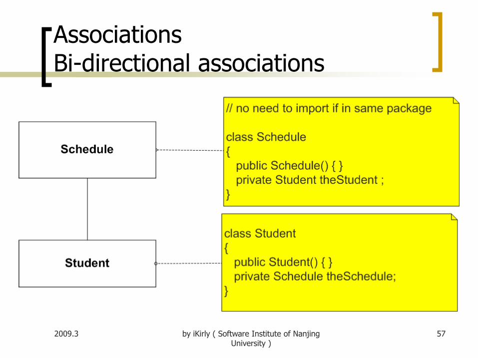
association
An association is a structural relationship that specifies that objects of one thing are connected to objects of another.
Given an association connecting two classes, you can navigate from an object of one class to an object of the other class, and vice versa.

2009.3 by iKirly ( Software Institute of Nanjing University )
37
association (cont’)
Graphically, an association is rendered as a solid line
connecting the same or different classes. Use
associations when you want to show structural
relationships.
There are Six adornments that apply to associations.
Name / Role / Mulitplicity / Navigation / Aggregation/
Composition

2009.3 by iKirly ( Software Institute of Nanjing University )
38
An association can have a name, and you use that
name to describe the nature of the relationship.
You can give a direction to the name by providing a
direction triangle that points in the direction you
intend to read the name, as …
name

2009.3 by iKirly ( Software Institute of Nanjing University )
39
name (cont’)

2009.3 by iKirly ( Software Institute of Nanjing University )
40
When a class participates in an association, it has aspecific role that it plays in that relationship;
A role is just the face the class at the near end ofthe association presents to the class at the otherend of the association.
You can explicitly name the role a class plays in anassociation.
role

2009.3 by iKirly ( Software Institute of Nanjing University )
41
role (cont’)

2009.3 by iKirly ( Software Institute of Nanjing University )
42
The multiplicity of a property is an indication of how
many objects may fill the property.
It is written as an expression that evaluates to a
range of values or an explicit value as …
Multiplicity

2009.3 by iKirly ( Software Institute of Nanjing University )
43
Multiplicity (cont’)

2009.3 by iKirly ( Software Institute of Nanjing University )
44
The most common multiplicities
1 (An order must have exactly one customer.)
0..1 (A corporate customer may or may not have a single sales rep.)
* (A customer need not place an Order and there is no upper limit to the number of Orders a Customer may place—zero or more orders.)
More generally, multiplicities are defined with a lower bound and an upper bound, such as 2..4
Multiplicity (cont’)

2009.3 by iKirly ( Software Institute of Nanjing University )
45
Navigation
Unless otherwise specified, navigation across an association is bidirectional.
However, there are some circumstances in which you'll want to limit navigation to just one direction.
2009.3 by iKirly ( Software Institute of Nanjing University )
46
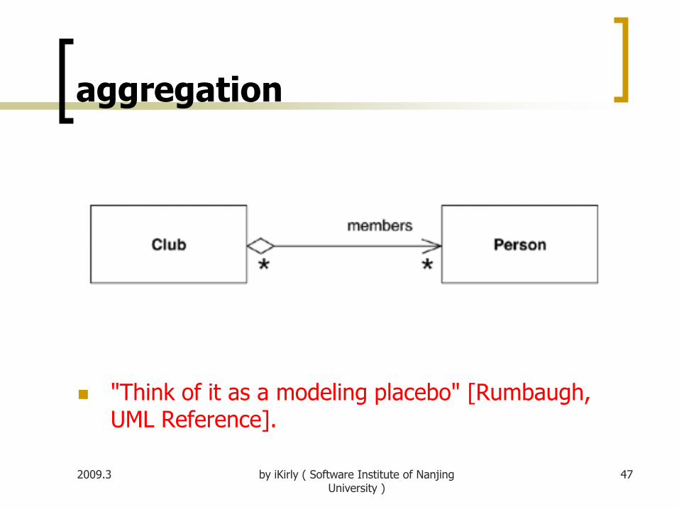
Aggregation is “Whole/part” relationship
one class represents a larger thing (the "whole"),
It consists of smaller things (the "parts").
It represents a "has-a" relationship
meaning that an object of the whole has objects of the
part.
It is specified by adorning a plain association with an
open diamond at the whole end, as…
aggregation
2009.3 by iKirly ( Software Institute of Nanjing University )
47
"Think of it as a modeling placebo" [Rumbaugh, UML Reference].
aggregation

2009.3 by iKirly ( Software Institute of Nanjing University )
48
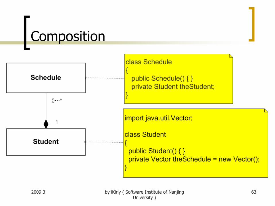
Composition
Composition is a form of aggregation, with strong ownership and coincident lifetime as part of the whole.

Constraint Rules
The basic constructs of association, attribute, and generalization do much to specify important constraints, but they cannot indicate every constraint. These constraints still need to be captured.
The UML allows you to use anything to describe constraints. The only rule is that you put them inside braces ({}).
You can use natural language, a programming language, or the UML's formal Object Constraint Language (OCL) [Warmer and Kleppe].
2009.3 by iKirly ( Software Institute of Nanjing University )
49

Interfaces and Abstract Classes
An abstract class is a class that cannot be directly instantiated.
Instead, you instantiate an instance of a subclass.
Typically, an abstract class has one or more operations that are abstract.
An abstract operation has no implementation ; it is pure declaration so that clients can bind to the abstract class.
2009.3 by iKirly ( Software Institute of Nanjing University )
50

Interfaces and Abstract Classes
An interface is a class that has no implementation; that is, all its features are abstract.
Interfaces correspond directly to interfaces in C# and Java and are a common idiom in other typed languages.
You mark an interface with the keyword «interface».
2009.3 by iKirly ( Software Institute of Nanjing University )
51

Interfaces and Abstract Classes
Classes have two kinds of relationships with interfaces: providing and requiring.
A class provides an interface if it is substitutable for the interface. In Java and .NET, a class can do that by implementing the interface or implementing a subtype of the interface. In C++, you subclass the class that is the interface.
A class requires an interface if it needs an instance of that interface in order to work. Essentially, this is having a dependency on the interface.
2009.3 by iKirly ( Software Institute of Nanjing University )
52

Interfaces and Abstract Classes
2009.3 by iKirly ( Software Institute of Nanjing University )
53

Interfaces and Abstract Classes
A more compact notation
Any class is a mix of an interface and an implementation
2009.3 by iKirly ( Software Institute of Nanjing University )
54

Mapping Representation: Notes
2009.3 55by iKirly ( Software Institute of Nanjing University )
Class Scope Attributes and Operations
2009.3 56by iKirly ( Software Institute of Nanjing University )
AssociationsBi-directional associations
2009.3 57by iKirly ( Software Institute of Nanjing University )

Association Navigability
2009.3 58by iKirly ( Software Institute of Nanjing University )

Association Roles
2009.3 59by iKirly ( Software Institute of Nanjing University )

Association Multiplicity
2009.3 60by iKirly ( Software Institute of Nanjing University )

Reflexive Associations
2009.3 61by iKirly ( Software Institute of Nanjing University )

Aggregation
2009.3 62by iKirly ( Software Institute of Nanjing University )
Composition
2009.3 63by iKirly ( Software Institute of Nanjing University )

Interfaces and Realizes Relationships
2009.3 64by iKirly ( Software Institute of Nanjing University )

Generalization & Abstract Class
2009.3 65by iKirly ( Software Institute of Nanjing University )

object diagram
An object diagram is a snapshot of the objects in a system at a point in time. Because it shows instances rather than classes, an object diagram is often called an instance diagram.
2009.3 by iKirly ( Software Institute of Nanjing University )
66

2009.3 by iKirly ( Software Institute of Nanjing University )
67
Component Diagrams
UML 1 had a distinctive symbol for a component. UML 2 removed that icon but allows you to annotate a class box with a similar-looking icon. Alternatively, you can use the «component» keyword.

2009.3 by iKirly ( Software Institute of Nanjing University )
68
An example component diagram
2009.3 by iKirly ( Software Institute of Nanjing University )
69
PART II Sequence Diagram
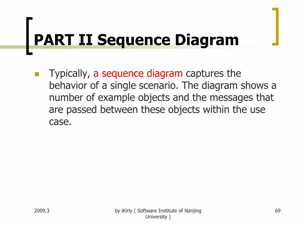
Typically, a sequence diagram captures the behavior of a single scenario. The diagram shows a number of example objects and the messages that are passed between these objects within the use case.

2009.3 by iKirly ( Software Institute of Nanjing University )
70
Sequence Diagram (cont’)
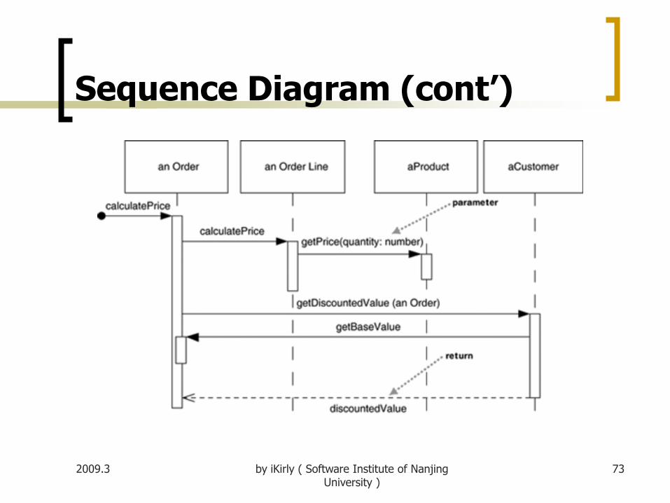
Example:
We have an order and are going to invoke a command on it to calculate its price.
To do that, the order needs to look at all the line items on the order and determine their prices, which are based on the pricing rules of the order line's products.
Having done that for all the line items, the order then needs to compute an overall discount, which is based on rules tied to the customer.

2009.3 by iKirly ( Software Institute of Nanjing University )
71
Sequence Diagram (cont’)

2009.3 by iKirly ( Software Institute of Nanjing University )
72
Sequence Diagram (cont’)
For another approach to this scenario.
The Order asks each Order Line to calculate its own Price.
The Order Line itself further hands off the calculation to the Product.
Similarly, to calculate the discount, the Order invokes a method on the Customer. Because it needs information from the Order to do this, the Customer makes a reentrant call (getBaseValue) to the Order to get the data.
2009.3 by iKirly ( Software Institute of Nanjing University )
73
Sequence Diagram (cont’)

2009.3 by iKirly ( Software Institute of Nanjing University )
74
Sequence Diagram (cont’)
The sequence diagram indicates the differences in
how the participants interact.
No1 : centralized control
with one participant pretty much doing all the processing
and other participants there to supply data.
No2 : distributed control
in which the processing is split among many participants,
each one doing a little bit of the algorithm

2009.3 by iKirly ( Software Institute of Nanjing University )
75
Creating and Deleting Participants
2009.3 by iKirly ( Software Institute of Nanjing University )
76
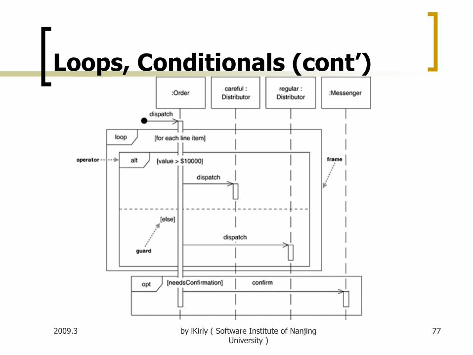
Loops, Conditionals
A common issue with sequence diagrams is how to show looping and conditional behavior.
The first thing to point out is that this isn't what sequence diagrams are good at. If you want to show control structures like this, you are better off with an activity diagram or indeed with code itself.
That said, here's the notation to use. Both loops and conditionals use interaction frames, which are ways of marking off a piece of a sequence diagram.
2009.3 by iKirly ( Software Institute of Nanjing University )
77
Loops, Conditionals (cont’)
2009.3 by iKirly ( Software Institute of Nanjing University )
78
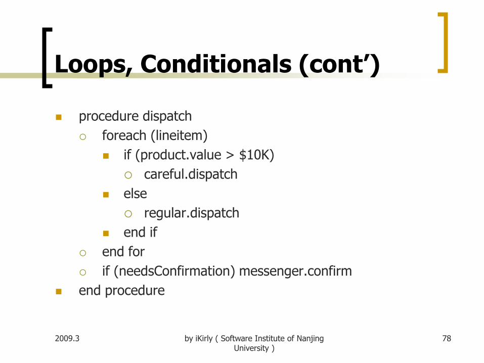
Loops, Conditionals (cont’)
procedure dispatch
foreach (lineitem)
if (product.value > $10K)
careful.dispatch
else
regular.dispatch
end if
end for
if (needsConfirmation) messenger.confirm
end procedure

2009.3 by iKirly ( Software Institute of Nanjing University )
79
Loops, Conditionals (cont’)
Common Operators for Interaction Frames Operator
Alt : Alternative multiple fragments; only the one whose
condition is true will execute
Opt : Optional; the fragment executes only if the supplied
condition is true. Equivalent to an alt with only one trace
Par : Parallel; each fragment is run in parallel.
Loop : Loop; the fragment may execute multiple times,
and the guard indicates the basis of iteration

2009.3 by iKirly ( Software Institute of Nanjing University )
80
Loops, Conditionals (cont’)
Common Operators (cont’)
Region : Critical region; the fragment can have only one
thread executing it at once.
Neg : Negative; the fragment shows an invalid
interaction.
Ref : Reference; refers to an interaction defined on
another diagram. The frame is drawn to cover the lifelines
involved in the interaction. You can define parameters and
a return value.
Sd : Sequence diagram; used to surround an entire
sequence diagram, if you wish.
2009.3 by iKirly ( Software Institute of Nanjing University )
81
Synchronous and Asynchronous
If a caller sends a synchronous message, it must wait until the message is done, such as invoking a subroutine. (filled arrowheads )
If a caller sends an asynchronous message, it can continue processing and doesn't have to wait for a response. (stick arrowheads )
You see asynchronous calls in multithreaded applications and in message-oriented middleware. Asynchrony gives better responsiveness and reduces the temporal coupling but is harder to debug.

2009.3 by iKirly ( Software Institute of Nanjing University )
82
When to Use Sequence Diagrams
Use sequence diagrams when you want to look at
the behavior of several objects within a single use
case.
Sequence diagrams are good at showing
collaborations among the objects; they are not so
good at precise definition of the behavior.

2009.3 by iKirly ( Software Institute of Nanjing University )
83
When to Use Sequence Diagrams
If you want to look at the behavior of a single
object across many use cases, use a state diagram.
If you want to look at behavior across many use
cases or many threads, consider an activity
diagram.
If you want to explore multiple alternative
interactions quickly, you may be better off with CRC
(Class-Responsibility-Collaboration) cards, as that
avoids a lot of drawing and erasing.

2009.3 by iKirly ( Software Institute of Nanjing University )
84
Part III State Machine Diagrams
A state machine is a behavior that specifies the
sequences of states an object goes through during
its lifetime in response to events, together with its
responses to those events.
A state is a condition or situation during the life of
an object during which it satisfies some condition,
performs some activity, or waits for some event.

2009.3 by iKirly ( Software Institute of Nanjing University )
85
State Machine Diagrams (cont’)
A transition is a relationship between two states
indicating that an object in the first state will
perform certain actions and enter the second state
when a specified event occurs and specified
conditions are satisfied.
Graphically, a state is rendered as a rectangle with
rounded corners. A transition is rendered as a solid
directed line.

2009.3 by iKirly ( Software Institute of Nanjing University )
86
State Machine Diagrams (cont’)

2009.3 by iKirly ( Software Institute of Nanjing University )
87
A simple state machine diagram
A controller for a secret panel
In the castle, I want to keep my valuables in a safe that's hard to find.
So to reveal the lock to the safe, I have to remove a strategic candle from its holder, but this will reveal the lock only while the door is closed.
Once I can see the lock, I can insert my key to open the safe.
For extra safety, I make sure that I can open the safe only if I replace the candle first. If a thief neglects this precaution, I'll unleash a nasty monster to devour him.

2009.3 by iKirly ( Software Institute of Nanjing University )
88
A simple state machine diagram

2009.3 by iKirly ( Software Institute of Nanjing University )
89
A simple state machine diagram
Each transition has a label that comes in three parts: trigger-signature [guard]/activity.
The trigger-signature is usually a single event that triggers a potential change of state.
The guard, if present, is a Boolean condition that must be true for the transition to be taken.
The activity is some behavior that's executed during the transition. It may be any behavioral expression.
2009.3 by iKirly ( Software Institute of Nanjing University )
90
A simple state machine diagram
All three parts to a transition are optional.
A missing activity indicates that you don't do anything during the transition.
A missing guard indicates that you always take the transition if the event occurs.
A missing trigger-signature is rare but does occur. It indicates that you take the transition immediately, which you see mostly with activity states

2009.3 by iKirly ( Software Institute of Nanjing University )
91
Implementing State Diagrams
A state diagram can be implemented in
three main ways:
nested switch,
the State pattern,
and state tables.
2009.3 by iKirly ( Software Institute of Nanjing University )
92
nested switch
The most direct approach to handling a state
diagram is a nested switch statement, such as
nested switch sample.
Although it's direct, it's long-winded, even for this
simple case. It's also very easy for this approach to
get out of control .
2009.3 by iKirly ( Software Institute of Nanjing University )
93
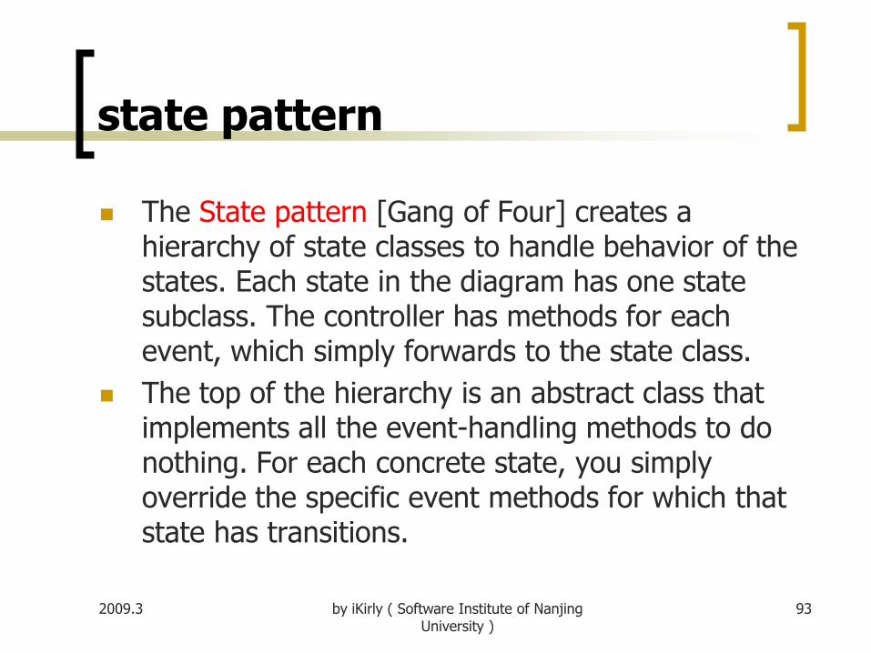
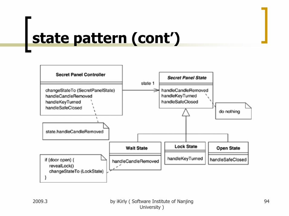
state pattern
The State pattern [Gang of Four] creates a hierarchy of state classes to handle behavior of the states. Each state in the diagram has one state subclass. The controller has methods for each event, which simply forwards to the state class.
The top of the hierarchy is an abstract class that implements all the event-handling methods to do nothing. For each concrete state, you simply override the specific event methods for which that state has transitions.
2009.3 by iKirly ( Software Institute of Nanjing University )
94
state pattern (cont’)

2009.3 by iKirly ( Software Institute of Nanjing University )
95
state table
The state table approach captures the state diagram information as data.
Source State
Target State
Event Guard Procedure
Wait LockCandle
removedDoor closed Reveal lock
Lock Open Key turned Candle in Open safe
Lock Final Key turned Candle outRelease killer
rabbit
Open Wait Safe closed

2009.3 by iKirly ( Software Institute of Nanjing University )
96
Part IV Activity Diagrams
Activity diagrams are a technique to describe
procedural logic, business process, and work flow.
In many ways, they play a role similar to
flowcharts, but the principal difference between
them and flowchart notation is that they support
parallel behavior.

2009.3 by iKirly ( Software Institute of Nanjing University )
97
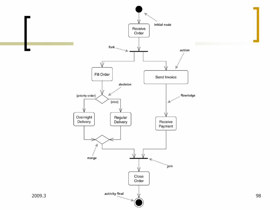
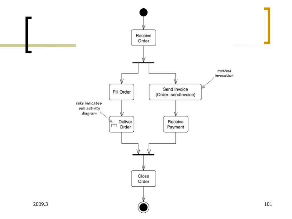
A simple activity diagram
Next figure shows a simple example of an activity
diagram. We begin at the initial node action and
then do the action Receive Order. Once that is
done, we encounter a fork. A fork has one incoming
flow and several outgoing concurrent flows.
It says that Fill Order, Send Invoice, and the
subsequent actions occur in parallel. Essentially,
this means that the sequence between them is
irrelevant.
2009.3 by iKirly ( Software Institute of Nanjing University )
98
2009.3 by iKirly ( Software Institute of Nanjing University )
99
A simple activity diagram
With a join, the outgoing flow is taken only when all the incoming flows reach the join. So you can close the order only when you have both received the payment and delivered.
Conditional behavior is delineated by decisions and merges.
A decision, called branch in UML 1, has a single incoming flow and several guarded out-bound flows.
A merge has multiple input flows and a single output. A merge marks the end of conditional behavior started by a decision.

2009.3 by iKirly ( Software Institute of Nanjing University )
100
Decomposing an Action
Actions can be decomposed into subactivities.
2009.3 by iKirly ( Software Institute of Nanjing University )
101

2009.3 by iKirly ( Software Institute of Nanjing University )
102
Partitions
If you want to show who does what, you can divide an activity diagram into partitions, which show which actions one class or organization unit carries out.

2009.3 by iKirly ( Software Institute of Nanjing University )
103
2009.3 by iKirly ( Software Institute of Nanjing University )
104
Partitions (cont’)
This style is often referred to as swim lanes, for obvious reasons and was the only form used in UML 1.x.
In UML 2, you can use a two-dimensional grid, so the swimming metaphor no longer holds water. You can also take each dimension and divide the rows or columns hierarchically.