Embed Size (px)
Citation preview

Copyright © 1998-2010 Sparx Systems Pty Ltd
Extending UML With EnterpriseArchitect
Enterprise Architect is an intuitive, flexible and powerful UMLanalysis and design tool for building robust and maintainable
software.
This booklet explains how to use Enterprise Architect to extendthe scope of UML in developing models.

All rights reserved. No parts of this work may be reproduced in any form or by any means - graphic, electronic, ormechanical, including photocopying, recording, taping, or information storage and retrieval systems - without thewritten permission of the publisher.
Products that are referred to in this document may be either trademarks and/or registered trademarks of therespective owners. The publisher and the author make no claim to these trademarks.
While every precaution has been taken in the preparation of this document, the publisher and the author assume noresponsibility for errors or omissions, or for damages resulting from the use of information contained in this documentor from the use of programs and source code that may accompany it. In no event shall the publisher and the author beliable for any loss of profit or any other commercial damage caused or alleged to have been caused directly orindirectly by this document.
Printed: May 2010
Extending UML With Enterprise Architect
© 1998-2010 Sparx Systems Pty Ltd
PublisherSpecial thanks to:
All the people who have contributed suggestions, examples, bugreports and assistance in the development of Enterprise Architect.The task of developing and maintaining this tool has been greatlyenhanced by their contribution.Managing Editor
Technical Editors
Sparx Systems
Geoffrey Sparks
Brad MaxwellSimon McNeillyNeil CapeyNithiya UgavinaVimal KumarSharon XieSam Mancarella
IContents
© 1998-2010 Sparx Systems Pty Ltd
Table of Contents
Foreword 1
Extending Models 2
................................................................................................................................... 4UML Profiles
.......................................................................................................................................................... 5Use Profiles
......................................................................................................................................................... 6Import a UML Profile
......................................................................................................................................................... 7Add Profile Objects and Features to a Diagram
......................................................................................................................................................... 8Tagged Values in Profiles
......................................................................................................................................................... 8Synchronize Tagged Values and Constraints
.......................................................................................................................................................... 10Profile References
......................................................................................................................................................... 10Supported Types
......................................................................................................................................................... 11Profile Structure
......................................................................................................................................................... 12Attributes Supported in XML Profile
......................................................................................................................................................... 13Example Profile
................................................................................................................................... 15UML Stereotypes
.......................................................................................................................................................... 16Apply Stereotypes
.......................................................................................................................................................... 17Stereotype Selector
.......................................................................................................................................................... 18Stereotype Visibility
.......................................................................................................................................................... 19Standard Stereotypes
.......................................................................................................................................................... 20Stereotypes with Alternative Images
................................................................................................................................... 22UML Patterns
.......................................................................................................................................................... 22Create a Pattern
.......................................................................................................................................................... 25Import a Pattern
.......................................................................................................................................................... 25Use a Pattern
................................................................................................................................... 28MDG Technologies
.......................................................................................................................................................... 28Import MDG Technologies
.......................................................................................................................................................... 30Work with MDG Technologies
......................................................................................................................................................... 32Manage MDG Technologies
......................................................................................................................................... 33Access Remote MDG Technologies
.......................................................................................................................................................... 34Archimate
.......................................................................................................................................................... 37BPEL
......................................................................................................................................................... 38Create a BPEL Model
......................................................................................................................................................... 40Model a BPEL Process
......................................................................................................................................... 41Model Start Event
......................................................................................................................................... 44Model End Event
......................................................................................................................................... 47Model Intermediate Event
......................................................................................................................................... 51Model Gateway
......................................................................................................................................... 53Model Activity
......................................................................................................................................... 58Model Pool
......................................................................................................................................................... 59Model Sequence Flow Connector
......................................................................................................................................................... 61Create Assignments
......................................................................................................................................................... 63Generate BPEL
......................................................................................................................................................... 64Create a BPEL Web Service
......................................................................................................................................................... 65BPEL Model Validation
.......................................................................................................................................................... 67BPMN
......................................................................................................................................................... 70Change BPMN Element Appearance
......................................................................................................................................................... 71Migrate BPMN 1.0 Model to BPMN 1.1
.......................................................................................................................................................... 72Data Flow Diagrams
.......................................................................................................................................................... 74Entity Relationship Diagrams (ERDs)
.......................................................................................................................................................... 76Eriksson-Penker Extensions
.......................................................................................................................................................... 79GoF Patterns
.......................................................................................................................................................... 80ICONIX

ContentsII
Extending UML With Enterprise Architect
.......................................................................................................................................................... 83Mind Mapping
.......................................................................................................................................................... 85SoaML
.......................................................................................................................................................... 87SPEM
......................................................................................................................................................... 89SPEM Toolbox Pages
.......................................................................................................................................................... 93SysML
......................................................................................................................................................... 94SysML Model Elements
......................................................................................................................................................... 95SysML Block Definition
......................................................................................................................................................... 97SysML Internal Block
......................................................................................................................................................... 98SysML Parametrics
......................................................................................................................................................... 100SysML Activity
......................................................................................................................................................... 102SysML Interaction
......................................................................................................................................................... 103SysML State Machine
......................................................................................................................................................... 104SysML Use Case
......................................................................................................................................................... 105SysML Requirements
Index 107

Foreword
This user guide explains how to use EnterpriseArchitect to extend the scope of UML in
developing models.
1Foreword
© 1998-2010 Sparx Systems Pty Ltd
| 2
Extending UML With Enterprise Architect
Extending Models
Enterprise Architect enables you to create models using UML. However, it also enables you to go muchfurther, extending the scope both of your modeling and of the UML components you use, as outlined below.
Requirements Management
Gathering requirements is typically the first step in developing a solution, be it for developing a softwareapplication or for detailing a business process. Requirements are essentially 'what the system must do'. The requirements management built into Enterprise Architect provides full support for defining, organizing andmanaging the requirements that drive the project. For further information, see Requirements Management.
UML Stereotypes
Stereotypes are an inbuilt mechanism for logically extending or altering the meaning, display and syntax of amodel element. Different model elements have different standard stereotypes associated with them. You canalso define your own stereotypes.
For further information on stereotypes, see the UML Stereotypes topic.
UML Profiles
UML Profiles are a means of extending UML, which enables you to build models in particular domains. AProfile is a collection of additional stereotypes and Tagged Values applied to elements, attributes, methodsand connectors, which together describe some particular modeling problem and facilitate modeling constructsin that domain.
For further information on Profiles, see the UML Profiles topic.
UML Patterns
Patterns are groups of collaborating Objects/Classes that can be abstracted from a general set of modelingscenarios (that is, parameterized collaborations). They generally describe how to solve an abstract problem,and are an excellent means of achieving re-use and building in robustness.
For more information on Patterns, see the UML Patterns topic.
MDG Technologies
The Model Driven Generation (MDG) Technologies enable you to access and use the resources of a specifictechnology within Enterprise Architect. Interfaces to some technologies, such as BPMN and Iconix, areintegrated with Enterprise Architect, whilst interfaces to others such as Eclipse and Visual Studio can beadded separately. You can also link to technologies that you have created yourself.
For more information on MDG Technologies, see the MDG Technologies topic.
Business Modeling
Modeling the business process is an essential part of any software development process. It enables you toestablish the broad outline and procedures that govern what it is a business does. As the Business ProcessModel typically has a broader range than just the software system being considered, it also enables you toclearly map what is in the scope of the proposed system and what is to be implemented in other ways.
Systems Engineering Modeling
Model Based Systems Engineering is a powerful way to capture vital design information in any complexsystems engineering development using the Systems Modeling Language (SysML). It enables you to definesystem requirements, operating constraints and performance characteristics of a system under development.
15
4
22
28

| 3
© 1998-2010 Sparx Systems Pty Ltd
It also allows you to capture the system architecture using well-formed interface specifications and reusablesubsystem components.

UML Profiles | 4
Extending UML With Enterprise Architect
1 UML Profiles
What are UML Profiles?
UML Profiles provide a means of extending UML, which enables you to build UML models in particulardomains. They are based on additional stereotypes and Tagged Values that are applied to elements,attributes, methods, connectors, connector ends and so on. A Profile is a collection of such extensions thattogether describe some particular modeling problem and facilitate modeling constructs in that domain. Forexample, the UML Profile for XML describes a set of extensions to basic UML model elements to enableaccurate modeling of XSD Schemas (see Modeling XML Applications with UML, David Carlson, p. 310).
Enterprise Architect has a generic UML Profile mechanism for loading and working with different Profiles.UML Profiles for Enterprise Architect are specified in XML files, with a specific format; see the examples inthis topic. You can import these XML files into Enterprise Architect as part of an MDG Technology orthrough the Resources window. Once imported, you can drag and drop Profile elements onto the currentdiagram. Enterprise Architect attaches the stereotype, Tagged Values and default values, notes and evenmetafile if one is specified, to the new element. You can also drag and drop attributes and operations ontoexisting Classes and have them immediately added with the specified stereotype and values.
The imported Profile also automatically generates a page of elements and relationships in the EnterpriseArchitect UML Toolbox.
Note:
To control the appearance of elements, you can also set a default element template. For more information,see the Set Element Templates Package topic in UML Modeling With Enterprise Architect - UML ModelingTool.
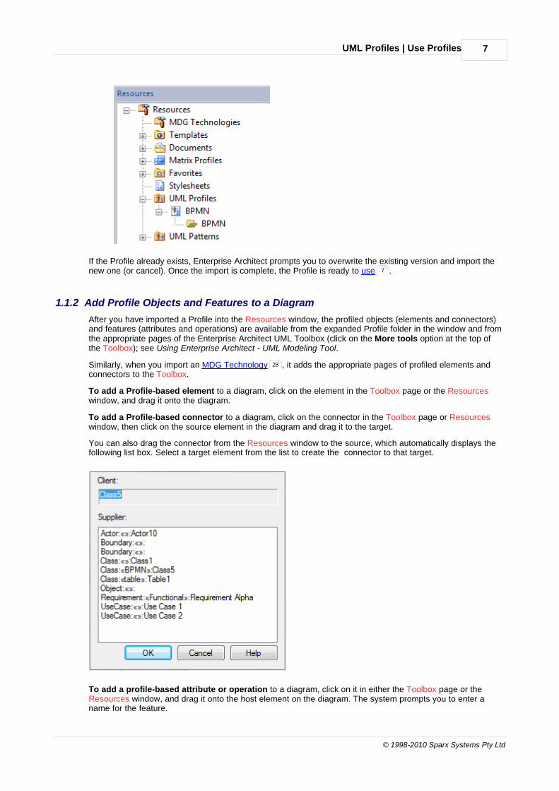
Profiles in the Resources Window
The Resources window contains a tree structure with entries for items such as MDG Technologies,Documents, Stylesheets, Matrix profiles and UML Profiles. The UML Profiles node initially contains no entries;to be able to use Profiles you must import them into Enterprise Architect from supplied XML files.
10
5
13
6 28
UML Profiles | 5
© 1998-2010 Sparx Systems Pty Ltd
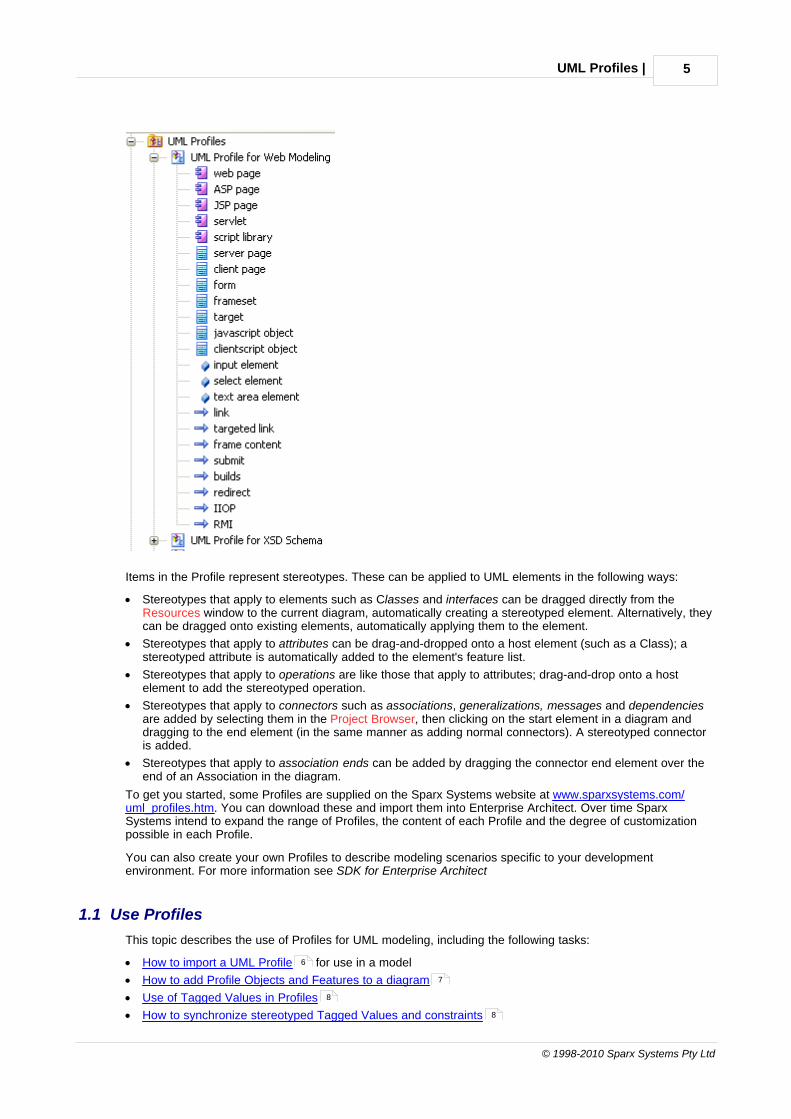
Items in the Profile represent stereotypes. These can be applied to UML elements in the following ways:
· Stereotypes that apply to elements such as Classes and interfaces can be dragged directly from theResources window to the current diagram, automatically creating a stereotyped element. Alternatively, theycan be dragged onto existing elements, automatically applying them to the element.
· Stereotypes that apply to attributes can be drag-and-dropped onto a host element (such as a Class); astereotyped attribute is automatically added to the element's feature list.
· Stereotypes that apply to operations are like those that apply to attributes; drag-and-drop onto a hostelement to add the stereotyped operation.
· Stereotypes that apply to connectors such as associations, generalizations, messages and dependenciesare added by selecting them in the Project Browser, then clicking on the start element in a diagram anddragging to the end element (in the same manner as adding normal connectors). A stereotyped connectoris added.
· Stereotypes that apply to association ends can be added by dragging the connector end element over theend of an Association in the diagram.
To get you started, some Profiles are supplied on the Sparx Systems website at www.sparxsystems.com/uml_profiles.htm. You can download these and import them into Enterprise Architect. Over time SparxSystems intend to expand the range of Profiles, the content of each Profile and the degree of customizationpossible in each Profile.
You can also create your own Profiles to describe modeling scenarios specific to your developmentenvironment. For more information see SDK for Enterprise Architect
1.1 Use Profiles
This topic describes the use of Profiles for UML modeling, including the following tasks:
· How to import a UML Profile for use in a model
· How to add Profile Objects and Features to a diagram
· Use of Tagged Values in Profiles
· How to synchronize stereotyped Tagged Values and constraints
6
7
8
8
UML Profiles | Use Profiles6
Extending UML With Enterprise Architect
A Technology Developer might create a new Profile, which they can save (export) to disk for future UMLmodels. The processes of creating and exporting a new UML Profile are described in SDK for EnterpriseArchitect
1.1.1 Import a UML Profile
Note:
This topic describes importing a stand-alone Profile. You can also embed Profiles in an MDG Technology andimport the Technology file into the Enterprise Architect installation directory.
To import a Profile you must have a suitable Profile XML file, such as the Profiles supplied on the SparxSystems website at www.sparxsystems.com/uml_profiles.htm. If the Profile includes references to anymetafiles, they should be in the same directory as the Profile XML file.
Import a Profile
To import a Profile, follow the steps below:
1. Open the Resources window (View | Other Project Tools | Resources).
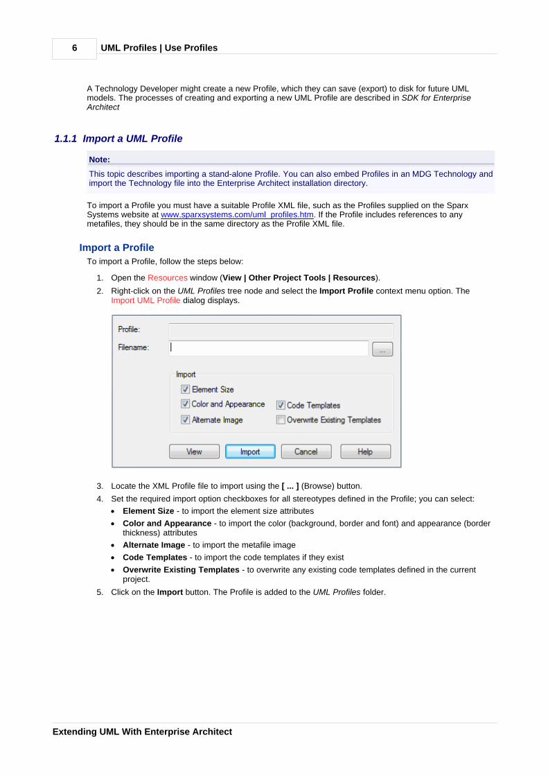
2. Right-click on the UML Profiles tree node and select the Import Profile context menu option. TheImport UML Profile dialog displays.
3. Locate the XML Profile file to import using the [ ... ] (Browse) button.
4. Set the required import option checkboxes for all stereotypes defined in the Profile; you can select:
· Element Size - to import the element size attributes
· Color and Appearance - to import the color (background, border and font) and appearance (borderthickness) attributes
· Alternate Image - to import the metafile image
· Code Templates - to import the code templates if they exist
· Overwrite Existing Templates - to overwrite any existing code templates defined in the currentproject.
5. Click on the Import button. The Profile is added to the UML Profiles folder.
UML Profiles | Use Profiles 7
© 1998-2010 Sparx Systems Pty Ltd
If the Profile already exists, Enterprise Architect prompts you to overwrite the existing version and import thenew one (or cancel). Once the import is complete, the Profile is ready to use .
1.1.2 Add Profile Objects and Features to a Diagram
After you have imported a Profile into the Resources window, the profiled objects (elements and connectors)and features (attributes and operations) are available from the expanded Profile folder in the window and fromthe appropriate pages of the Enterprise Architect UML Toolbox (click on the More tools option at the top ofthe Toolbox); see Using Enterprise Architect - UML Modeling Tool.
Similarly, when you import an MDG Technology , it adds the appropriate pages of profiled elements andconnectors to the Toolbox.
To add a Profile-based element to a diagram, click on the element in the Toolbox page or the Resourceswindow, and drag it onto the diagram.
To add a Profile-based connector to a diagram, click on the connector in the Toolbox page or Resourceswindow, then click on the source element in the diagram and drag it to the target.
You can also drag the connector from the Resources window to the source, which automatically displays thefollowing list box. Select a target element from the list to create the connector to that target.
To add a profile-based attribute or operation to a diagram, click on it in either the Toolbox page or theResources window, and drag it onto the host element on the diagram. The system prompts you to enter aname for the feature.
7
28

UML Profiles | Use Profiles8
Extending UML With Enterprise Architect
1.1.3 Tagged Values in Profiles
Stereotypes within a UML Profile can have one or more associated Tagged Values. When you create anelement based on a UML Profile Stereotype by dragging from the Resources window to a diagram, anyassociated Tagged Values are added to the element as well. Tagged Values and Profiles are an excellent wayto extend the use of Enterprise Architect and the power of UML modeling.
For example, in the UML Profile for XSD, there is an XSDComplexType stereotype, which has the followingTagged Value declaration:
<TaggedValues><Tag name="mixed" description="Determines whether this element can contain mixed element and character content.See the W3C XML Schema recommendation"/><Tag name="modelGroup" description="Overrides the package-level default model group" values="all | sequence |choice" default="choice"/><Tag name="memberNames" description="Overrides the package-level default for naming complexType definitions"/></TaggedValues>
When you create an element from the XSDComplexType stereotype (by dragging from the Profile Elementspage of the Enterprise Architect UML Toolbox onto a diagram), the Tagged Values are added automatically.
Tagged Values that have default values are automatically set and displayed in the element tags section, ifapplicable. When you select the element, the Tagged Values window displays all the associated tags,including ones that have no value set. Also note that Tagged Values in the Profile that have a Values section(for example, values="element | attribute | both" default="both") enable you to select the non-default valuesfrom a drop-down list. (See the enum Tagged Value Type in the Predefined Structured Types topic in SDK forEnterprise Architect.) Where no Value list exists, the tag accepts free text.
1.1.4 Synchronize Tagged Values and Constraints
When you create an element, attribute, operation or link from a UML Profile item, you add the Tagged Valuesand constraints from the Profile. Over time you might modify the constraints or the notes and tags of theTagged Values of a particular profiled item, so the items already created might be missing additional TaggedValue tags and notes, or constraints.
Similarly, you might have manually set the stereotype on a set of elements and now want them to receive theTagged Values and constraints associated with that stereotype.
To make sure you have all the related Tagged Values and constraints, use the Synch Tagged Values andConstraints function. This operates in two ways:
· If the Profile was created in an MDG Technology File and is not held in the Resources window
· If the Profile is held in the Resources window.
Synchronize Items In MDG Technology File
When an MDG Technology file is deployed in Enterprise Architect, the Profile is accessed through the Toolboxpages also defined in the file. The profiled elements in these Toolbox pages automatically trigger an additionalcontext menu option, Synchronize Stereotype.
The MDG Technology can be an in-house customized Add-In, or an external technology such as thoseprovided with Enterprise Architect; for example, BPMN 1.1.
To synchronize elements created using the MDG Technology pages of the Toolbox, follow the steps below:
1. Open a diagram containing elements to be synchronized. Ensure that the Toolbox displays pagescontaining the stereotyped profile elements from the MDG Technology.

UML Profiles | Use Profiles 9
© 1998-2010 Sparx Systems Pty Ltd
Note:
The diagram does not necessarily have to contain profiled elements. The function operates from the Toolbox. However, you might prefer to see the immediate effect of the synchronization on elementproperties and Tagged Values, by opening an appropriate diagram at the start.
2. Right-click on the element profile in the Toolbox (for example, the BPMN 1.1 Activity element). TheToolbox context menu displays.
3. Click on the Synchronize Stereotype menu option. The Synch Profiled Elements dialog displays.
4. Click on the OK button to proceed. The Actions list is populated with the items that have been modifiedand the changes that were made.
You can review any changes by displaying the element Properties dialog and by opening the Tagged Valueswindow and clicking on an appropriate profiled element.
You can also quickly synchronize the tags and constraints of a single element in a diagram by dragging theupdated profile element from the Toolbox page onto the element in the diagram. Select the Apply«stereotype» context menu option.
Synchronize Items In Resources Window
To synchronize elements created using a Profile in the Resources window, follow the steps below:
1. Locate the required UML Profile in the Resources window.
2. Locate the stereotyped profile element.
3. Right-click on it to display the context menu, and select the Synch Tagged Values and Constraintsoption. The Synch Profiled Elements dialog displays.
4. Click on the OK button to proceed. The Actions list is populated with the items that have been modifiedand the changes that were made.

UML Profiles | Profile References10
Extending UML With Enterprise Architect
1.2 Profile References
UML Profile XML File Format Information
Enterprise Architect provides a facility to import pre-defined elements, operations, attributes and connectorsas a source of re-useable components that meet common modeling requirements (such as profiles for XMLschema and for business process modeling). This topic provides a quick list of the types of data that can bepre-defined and the characteristics of each type.
This topic gives you a reference to:
· Supported Types of stereotype with Tagged Values and/or constraints
· Profile Structure
· Supported Attributes
· Example of the XML file that constitutes a Profile
1.2.1 Supported Types
A UML profile is made up of one or more stereotypes that might have Tagged Values and constraints. Thetable below and the Supported Attributes table define what can be stereotyped and what information mustbe supplied.
List of All Supported Types in AppliesTo/Apply Node
AppliesTo / Apply Type Tags Constraint Metafile
"actor" Element Yes Yes Yes
"package" Package Yes Yes Yes
"usecase" Element Yes Yes Yes
"collaboration" Element Yes Yes Yes
"class" Element Yes Yes Yes
"table" Element Yes Yes Yes
"component" Element Yes Yes Yes
"node" Element Yes Yes Yes
"object" Element Yes Yes Yes
"sequence" Element Yes Yes Yes
"entity" Element Yes Yes Yes
"screen" Element Yes Yes Yes
"GUIElement" Element Yes Yes Yes
"requirement" Element Yes Yes
"state" Element Yes Yes
"activity" Element Yes Yes Yes
"interface" Element Yes Yes Yes
"event" Element Yes Yes
"issue" Element Yes Yes
"change" Element Yes Yes
10
11
12
13
12

UML Profiles | Profile References 11
© 1998-2010 Sparx Systems Pty Ltd
AppliesTo / Apply Type Tags Constraint Metafile
"hyperlink" Element Yes
"attribute" Attribute Yes Yes
"operation" Operation Yes Yes
"association" Connector Yes Yes
"associationEnd" AssociationEnd
"generalization" Connector Yes Yes
"dependency" Connector Yes Yes
"transition" Connector Yes Yes
"objectflow" Connector Yes Yes
"startnode" Element Yes Yes
"stopnode" Element Yes Yes
"note" Element Yes Yes
"decision" Element Yes Yes
"aggregation" Connector Yes Yes
1.2.2 Profile Structure
UML Profiles for Enterprise Architect are distributed in XML format. The file has the following format:
General Header Details
<?xml version="1.0" encoding="utf-8" ?><UMLProfile profiletype="uml2"> <!--Profile name, version number and general notes --><Documentation id="XSDSchema" name="UML Profile for XSD Schema" version="1.0" notes="Defines a set ofstereotypes and tagged values for XSD Schemas"/> <!-- The profile content --> <Content><!-- List of stereotypes used in this profile. Can also include tagged values, constraints, metafile and descriptivecomments--> <Stereotypes>
Stereotype Definitions
The header is followed by one or more Stereotype definitions; for example:
<!-- «XSDComplexType» --><Stereotype name="XSDComplexType" notes="ComplexType definition generated in XML Schema"> <AppliesTo> <Apply type="class"/> </AppliesTo> <TaggedValues> <Tag name="mixed" description="URI to unique target namespace"/> <Tag name="modelGroup" description="Default model group used when generating complexType definitions for thisSchema" values="all | sequence | choice" default="choice"/> <Tag name="attributeMapping" description="Default for generating UML attributes as elements, attributes or bothwithin complexTypes" values="element | attribute| both" default="both"/> <Tag name="roleMapping" description="Prefix associated with namespace"/> <Tag name="memberNames" description="Schema version"/></TaggedValues>
<Constraints> <Constraint name="" type="" notes=""/></Constraints>

UML Profiles | Profile References12
Extending UML With Enterprise Architect
</Stereotype>
Note the specification of Stereotype name and notes. Also note the use of Tagged Values to set properties forthe Profile element. The Tagged Values can have a default value, can be empty and can specify enableablevalues. Tagged Values are edited in the Properties window of an element, method, attribute or connector.
You can also specify the default size, default comment and Metafile for drawing an element; see the fragmentbelow:
<Stereotype name="Router" cx="130" cy="100" notes="" metafile="router.emf">
In the above example, the metafile shape for this element is specified as 'router.emf'; when you load this Profile,the .emf file must be in the same directory as the Profile, otherwise the load fails.
Also note how to specify a default comment for an element. All white space between lines is ignored. To forcea line break, use the \n character. To force tabs, use \t.
<Comment> Some text here about how this works\n\t with comments being imported from the XML description in one long row.</Comment>
The example above would import like this:
Some text here about how this works with comments being imported from the XML description in one long row.
1.2.3 Attributes Supported in XML Profile
The table below lists the three main types of object you can define for the main XML element nodes in an XMLProfile document. These are the:
· Stereotype, which creates a visible entry in the UML Profile folder in the Resources window
· Tagged Values, which are additional properties that an element or connector support
· Constraints that apply to the model element.
Type Attribute Optional Notes
stereotype cx Yes Deprecated. Initial x coordinate of element.
cy Yes Deprecated. Initial y coordinate of element.
_image Yes Shape script definition.
_imageFile Yes Deprecated. Location of image file (.wmf).
metafile Yes Filename of associated metafile; this MUST be in the same directoryas the Profile XML.
name No Stereotype name.
notes Yes Notes visible in browser.
_sizeX Yes Initial width of the element, in pixels at 100% zoom.
_sizeY Yes Initial height of the element, in pixels at 100% zoom.
tag default Yes A default value; for example, 'true'.
description Yes A description of the tag; appears in the tag tab and for elements inthe Properties window setting notes.
name No Tag name.
values Yes List of possible values; values separated by ' | ' (<space>|<space>);for example, 'true | false'. For elements, populates the drop combo inthe tag section of the docked Properties window.
constraint name Yes Constraint name.

UML Profiles | Profile References 13
© 1998-2010 Sparx Systems Pty Ltd
Type Attribute Optional Notes
notes No Additional explanatory notes.
type Yes Constraint type (for example, 'pre' for precondition, 'post' forpostcondition).
1.2.4 Example Profile
Below is an example UML Profile showing the structure and use of the file:
<?xml version="1.0" encoding="UTF-8"?><UMLProfile>
<Documentation id="EAExample" name="UML Profile for Example" version="1" notes="An example set ofstereotypes and tagged values"/>
<!-- The profile content --><Content>
<!-- List of stereotypes used in this profile--><Stereotypes>
<!--A profile is a list of stereotypes, that apply to elements, connectors and features in a UMLmodel. Stereotypes can have set tagged values, constraints,
Valid targets, default dimensions. The examples below are a good starting point --><Stereotype name="SimpleStereotype" notes="Place notes about stereotype here"
metafile="router.emf"><!-- Place a list of types that this will apply to ... valid types are any UML element (class, interface, component, aggregation, generalization, association, transition, operation and attribute. Make sure
you use lowercase names, XML is case sensitive--><AppliesTo>
<Apply type="class"/><Apply type="interface"/><Apply type="node"/>
</AppliesTo><!--Add one or more tagged values for this stereotype. These are automatically added
to the target element when createdNote that you can specify a default value using "default=" and a pick list of values for
example " true | false" note the use of a " | " to separate values --><TaggedValues>
<Tag name="hasNamespace" description="Indicates element is bound toNamespace" default="true" values="true | false"/>
<Tag name="targetNamespacePrefix" description="Prefix associated withnamespace"/>
</TaggedValues><!-- Zero or more constraints to apply to element - specify name, type and notes --><Constraints>
<Constraint name="constraint1" type="pre" notes="My Notes"/></Constraints>
</Stereotype><!-- End of stereotype. When writing your own, you can duplicate a stereotype selection as
above and change it to start work on a new stereotype--><!-- «AnotherExample» --><Stereotype name="AnotherExample" cx="130" cy="100" notes="This element has a default
height and width specified"><AppliesTo>
<Apply type="class"/><Apply type="operation"/><Apply type="attribute"/>
</AppliesTo><TaggedValues>
<Tag name="memberNames" description="Schema version"/></TaggedValues><Constraints>
<Constraint name="constraint1" type="pre" notes="My Notes"/></Constraints>
</Stereotype><!-- «Aggregation» --><Stereotype name="aggregationLink" type="weak" notes="">
<AppliesTo><Apply type="aggregation"/>
</AppliesTo>

UML Profiles | Profile References14
Extending UML With Enterprise Architect
</Stereotype><!-- «Composition» --><Stereotype name="compositionLink" type="strong" notes="">
<AppliesTo><Apply type="aggregation"/>
</AppliesTo></Stereotype><!-- «IndexKey» --><Stereotype name="UniqueID" notes="">
<AppliesTo><Apply type="operation"/>
</AppliesTo><TaggedValues>
<Tag name="indexed" description="indicates if indexed or not" values="true| false" default="true"/>
</TaggedValues><Constraints>
<Constraint name="constraint1" type="pre" opType="pre" notes="My Notes"/>
<Constraint name="constraint2" type="pre" opType="post" notes="MyNotes"/>
</Constraints></Stereotype><!-- «Attribute» --><Stereotype name="attname" notes="">
<AppliesTo><Apply type="attribute"/>
</AppliesTo><Constraints>
<Constraint name="constraint1" type="pre" notes="My Notes"/></Constraints>
</Stereotype><!-- «Association» --><Stereotype name="assocname" notes="">
<AppliesTo><Apply type="association"/>
</AppliesTo><Constraints>
<Constraint name="constraint1" type="pre" notes="My Notes"/></Constraints>
</Stereotype></Stereotypes>
</Content></UMLProfile>
UML Stereotypes | 15
© 1998-2010 Sparx Systems Pty Ltd
2 UML Stereotypes
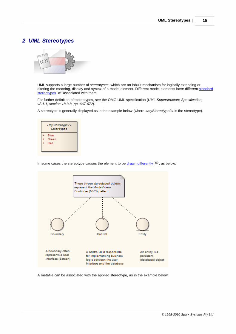
UML supports a large number of stereotypes, which are an inbuilt mechanism for logically extending oraltering the meaning, display and syntax of a model element. Different model elements have different standardstereotypes associated with them.
For further definition of stereotypes, see the OMG UML specification (UML Superstructure Specification,v2.1.1, section 18.3.8, pp. 667-672).
A stereotype is generally displayed as in the example below (where «myStereotype2» is the stereotype).
In some cases the stereotype causes the element to be drawn differently , as below:
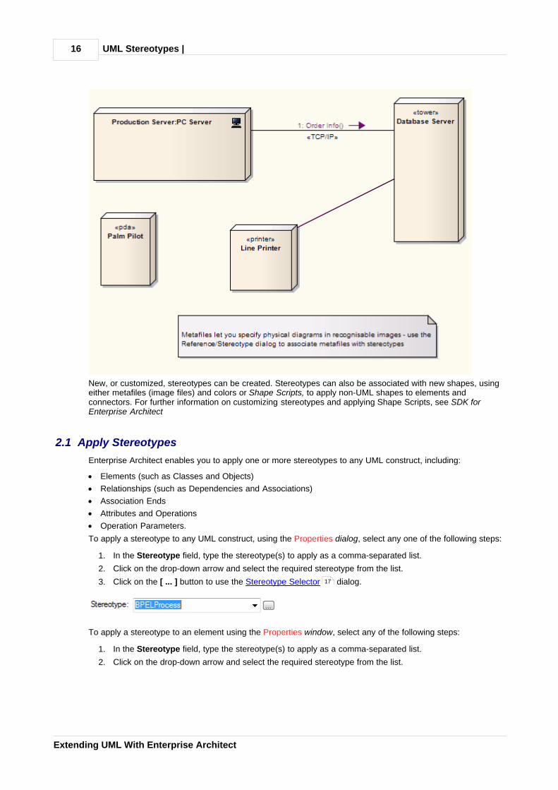
A metafile can be associated with the applied stereotype, as in the example below:
19
20
UML Stereotypes | 16
Extending UML With Enterprise Architect
New, or customized, stereotypes can be created. Stereotypes can also be associated with new shapes, usingeither metafiles (image files) and colors or Shape Scripts, to apply non-UML shapes to elements andconnectors. For further information on customizing stereotypes and applying Shape Scripts, see SDK forEnterprise Architect
2.1 Apply Stereotypes
Enterprise Architect enables you to apply one or more stereotypes to any UML construct, including:
· Elements (such as Classes and Objects)
· Relationships (such as Dependencies and Associations)
· Association Ends
· Attributes and Operations
· Operation Parameters.
To apply a stereotype to any UML construct, using the Properties dialog, select any one of the following steps:
1. In the Stereotype field, type the stereotype(s) to apply as a comma-separated list.
2. Click on the drop-down arrow and select the required stereotype from the list.
3. Click on the [ ... ] button to use the Stereotype Selector dialog.
To apply a stereotype to an element using the Properties window, select any of the following steps:
1. In the Stereotype field, type the stereotype(s) to apply as a comma-separated list.
2. Click on the drop-down arrow and select the required stereotype from the list.
17

UML Stereotypes | Apply Stereotypes 17
© 1998-2010 Sparx Systems Pty Ltd
3. Select the browse other stereotypes... option in the drop-down list to use the Stereotype Selectordialog.
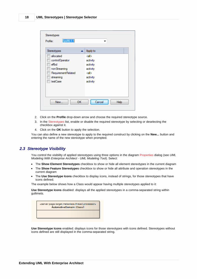
2.2 Stereotype Selector
The Stereotype Selector dialog enables you to apply one or more stereotypes to a UML construct, frommultiple stereotype sources such as Profiles or the Custom Stereotypes list. The appearance of the stereotypeis influenced by the stereotype visibility settings on the Diagram Properties dialog.
Select Stereotypes to Apply/Remove
1. On the element or connector Properties dialog, click on the [ ... ] button near the Stereotype field. TheStereotype for:<object type> dialog displays.
17
16
18
UML Stereotypes | Stereotype Selector18
Extending UML With Enterprise Architect
2. Click on the Profile drop-down arrow and choose the required stereotype source.
3. In the Stereotypes list, enable or disable the required stereotype by selecting or deselecting thecheckbox against it.
4. Click on the OK button to apply the selection.
You can also define a new stereotype to apply to the required construct by clicking on the New... button andentering the name of the new stereotype when prompted.
2.3 Stereotype Visibility
You control the visibility of applied stereotypes using three options in the diagram Properties dialog (see UMLModeling With Enterprise Architect - UML Modeling Tool). Select:
· The Show Element Stereotypes checkbox to show or hide all element stereotypes in the current diagram
· The Show Feature Stereotypes checkbox to show or hide all attribute and operation stereotypes in thecurrent diagram
· The Use Stereotype Icons checkbox to display icons, instead of strings, for those stereotypes that haveicons defined.
The example below shows how a Class would appear having multiple stereotypes applied to it:
Use Stereotype Icons disabled: displays all the applied stereotypes in a comma-separated string withingullimets.
Use Stereotype Icons enabled: displays icons for those stereotypes with icons defined. Stereotypes withouticons defined are still displayed in the comma-separated string.
UML Stereotypes | Stereotype Visibility 19
© 1998-2010 Sparx Systems Pty Ltd
2.4 Standard Stereotypes
Below is a list of standard element stereotypes (as provided in the EABase.eap base model), each enclosedby guillemets (« »):
Stereotype Base Class
«access» Permission
«become» Flow
«call» Usage
«copy» Flow
«create» Message
«derive» Abstraction
«destroy» Message
«document» Abstraction
«executable» Abstraction
«facade» Package
«file» Abstraction
«framework» Package
«friend» Permission
«global» AssociationEnd
«implementation» Class
«implementation» Generalization
«import» Permission
«instantiate» Usage
«invariant» Constraint
«library» Abstraction
«local» AssociationEnd
«metaclass» Class
«parameter» AssociationEnd
«postcondition» Constraint
«powertype» Class

UML Stereotypes | Standard Stereotypes20
Extending UML With Enterprise Architect
Stereotype Base Class
«precondition» Constraint
«process» Classifier
«refine» Abstraction
«requirement» Comment
«responsibility» Comment
«self» AssociationEnd
«send» Usage
«stub» Package
«table» Abstraction
«thread» Classifier
«trace» Abstraction
«type» Class
«utility» Classifier
2.5 Stereotypes with Alternative Images
You can alter the appearance of elements using stereotypes. This does not apply to elements that includeLifelines, such as those in Sequence diagrams.
If the stereotype has an associated metafile, when the stereotype is applied to a Class or other element thatsupports alternative graphical format, Enterprise Architect then draws the alternative image instead of thestandard one.

UML Stereotypes | Stereotypes with Alternative Images 21
© 1998-2010 Sparx Systems Pty Ltd

UML Patterns | 22
Extending UML With Enterprise Architect
3 UML Patterns
What is a Pattern?
Patterns are parameterized collaborations; that is, they are a group of collaborating Objects/Classes that canbe abstracted from a general set of modeling scenarios. Patterns are an excellent means of achieving re-useand building in robustness. As patterns are discovered in any new project, the basic pattern template fromprevious engagements can be re-used with the appropriate variable names modified for the current project.
Patterns generally describe how to solve an abstract problem, and it is the task of the pattern user to modifythe pattern elements to meet the demands of the current engagement.
Before using a pattern it must first be created as a standard UML diagram and then saved as an XMLpattern file. This XML file can then be imported as a UML resource that can be used in any model.
Sparx-Created GoF Patterns
To get you started with design patterns in Enterprise Architect, Sparx Systems provides you with an MDGtechnology for the patterns described in the book Design Patterns - Elements of Reusable Object-OrientedSoftware by Gamma et al., referred to as the 'Gang of Four' or GoF. These patterns are made availablethrough a set of Toolbox pages.
The pattern elements are drawn from the EABase.eap file, through the Resources window hierarchy.Therefore, if you are developing your model in a DBMS repository (or you inadvertently delete the GoFpatterns from your .eap file) you can download them as a 'zip' file from www.sparxsystems.com/uml_patterns.html.
Because the patterns are drawn from the Resources window, if you delete a pattern in the Resources windowthe equivalent Toolbox item cannot work. Therefore, if you cannot drop a pattern element from the Toolbox,check that it is still available in the Resources window.
3.1 Create a Pattern
To create a Pattern you first must model the Pattern as a standard UML diagram within Enterprise Architect.The following diagram was created from an example in the GoF book Design Patterns - Elements of ReusableObject-Oriented Software by Gamma et al.
22
25 25
79

UML Patterns | Create a Pattern 23
© 1998-2010 Sparx Systems Pty Ltd
Notes:
· In the Corporate, Business and Software Engineering, System Engineering and Ultimate editions ofEnterprise Architect, if security is enabled you must have Manage Diagrams permission to save a diagramas a Pattern. See User Security in UML Models.
· If your source diagram contains information flows, the Information Items Conveyed and Information FlowsRealized data is not copied into the Pattern.
Save a Diagram as a Pattern
To save a diagram as a Pattern, follow the steps below:
1. Select the Diagram | Save UML Pattern menu option. The Save Diagram as UML Pattern dialogdisplays.
UML Patterns | Create a Pattern24
Extending UML With Enterprise Architect
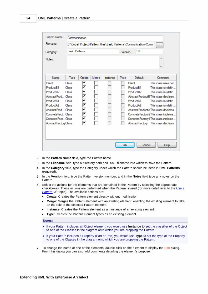
2. In the Pattern Name field, type the Pattern name.
3. In the Filename field, type a directory path and .XML filename into which to save the Pattern.
4. In the Category field, type the Category under which the Pattern should be listed in UML Patterns(required).
5. In the Version field, type the Pattern version number, and in the Notes field type any notes on thePattern.
6. Select the actions for the elements that are contained in the Pattern by selecting the appropriatecheckboxes. These actions are performed when the Pattern is used (for more detail refer to the Use aPattern topic). The available actions are:
· Create: Creates the Pattern element directly without modification
· Merge: Merges the Pattern element with an existing element, enabling the existing element to takeon the role of the selected Pattern element
· Instance: Creates the Pattern element as an instance of an existing element
· Type: Creates the Pattern element types as an existing element.
Notes:
· If your Pattern includes an Object element, you would use Instance to set the classifier of the Objectto one of the Classes in the diagram onto which you are dropping the Pattern.
· If your Pattern includes a Property (Port or Part) you would use Type to set the type of the Propertyto one of the Classes in the diagram onto which you are dropping the Pattern.
7. To change the name of one of the elements, double-click on the element to display the Edit dialog.From this dialog you can also add comments detailing the element's purpose.
25

UML Patterns | Create a Pattern 25
© 1998-2010 Sparx Systems Pty Ltd
8. Click on the OK button twice to save the Pattern. Once saved you can load it into EnterpriseArchitect as a Pattern in the Resources window (see Using Enterprise Architect - UML Modeling Tool).
3.2 Import a Pattern
Before using a previously created Pattern file in a UML model, you must first import it into the current UMLmodel; it is then available from the Resources window and optionally from the Enterprise Architect UMLToolbox. To import a UML Pattern you have previously saved, follow the steps outlined below:
1. Select the Resources window.
2. Right-click on the UML Patterns node. The context menu displays.
3. Select the Import UML Pattern menu option. The Select UML Pattern Import Filename dialog displays.
4. Locate the XML file to import.
5. Click on the Open button to import the Pattern.
The imported Pattern is placed in the appropriate category as defined in the XML file. If the category does notalready exist under UML Patterns, a new one is created.
Gang of Four patterns are integrated with Enterprise Architect in the EABase.eap file. However, if you createyour model in a DBMS repository (or you inadvertently delete the patterns from your model .eap file) you canuse the above procedure to download examples of the Gang of Four patterns from the GoF Patterns zip file onthe Sparx Systems website.
3.3 Use a Pattern
Using a Pattern enables you to use items defined in the Pattern with the UML model. Using Patterns enablesyou to rapidly create template solutions for code structures that perform the same type of task in othersituations.
To use a Pattern that you have previously imported into the model, follow the steps below:
1. Open the diagram into which to add the UML Pattern.
2. Select the Resources window.
3. Expand the UML Pattern folder and find the Pattern to add.
4. Either:
· Right-click on the Pattern and select the Add Pattern to Diagram context menu option or
· Drag and drop the Pattern from the Resources window onto the diagram.
(You can also view the Pattern details in read-only mode by selecting the View Pattern Details contextmenu option.)
The Add Pattern dialog displays.
25
22
25
UML Patterns | Use a Pattern26
Extending UML With Enterprise Architect
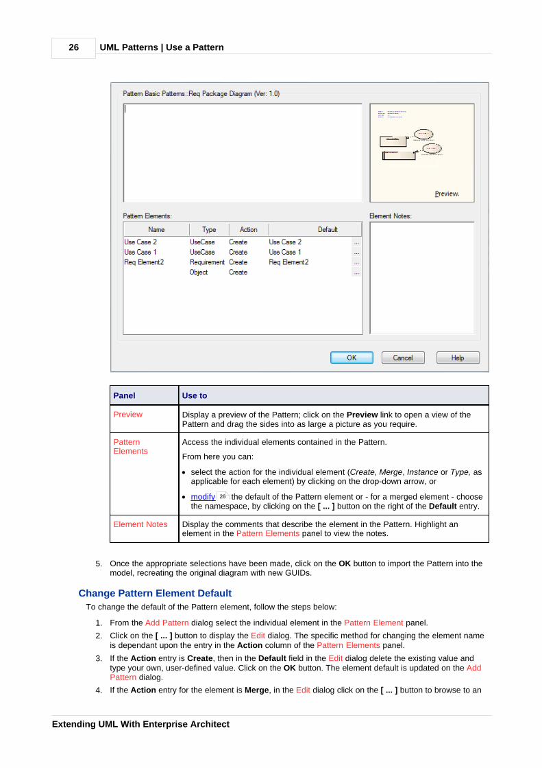
Panel Use to
Preview Display a preview of the Pattern; click on the Preview link to open a view of thePattern and drag the sides into as large a picture as you require.
PatternElements
Access the individual elements contained in the Pattern.
From here you can:
· select the action for the individual element (Create, Merge, Instance or Type, asapplicable for each element) by clicking on the drop-down arrow, or
· modify the default of the Pattern element or - for a merged element - choosethe namespace, by clicking on the [ ... ] button on the right of the Default entry.
Element Notes Display the comments that describe the element in the Pattern. Highlight anelement in the Pattern Elements panel to view the notes.
5. Once the appropriate selections have been made, click on the OK button to import the Pattern into themodel, recreating the original diagram with new GUIDs.
Change Pattern Element Default
To change the default of the Pattern element, follow the steps below:
1. From the Add Pattern dialog select the individual element in the Pattern Element panel.
2. Click on the [ ... ] button to display the Edit dialog. The specific method for changing the element nameis dependant upon the entry in the Action column of the Pattern Elements panel.
3. If the Action entry is Create, then in the Default field in the Edit dialog delete the existing value andtype your own, user-defined value. Click on the OK button. The element default is updated on the AddPattern dialog.
4. If the Action entry for the element is Merge, in the Edit dialog click on the [ ... ] button to browse to an
26

UML Patterns | Use a Pattern 27
© 1998-2010 Sparx Systems Pty Ltd
existing element classifier. The Select <Item> dialog displays.
5. Locate and select an existing element classifier. You can restrict the number of choices by selecting theelements from a specific namespace; to do this, click on the In Namespace drop-down arrow andselect a namespace. For more information regarding setting element classifiers see the UsingClassifiers topic in UML Modeling With Enterprise Architect - UML Modeling Tool.

MDG Technologies | 28
Extending UML With Enterprise Architect
4 MDG Technologies
The Model Driven Generation (MDG) Technologies enable you to access and use resources pertaining to aspecific technology in Enterprise Architect. You have various options for bringing MDG Technologies into usewith Enterprise Architect:
· Sparx Systems already provide some in the Enterprise Architect Install directory, such as Archimate ,BPEL , BPMN , Data Flow Diagrams , Entity Relationship Diagrams , ICONIX , MindMapping , and SPEM ; you can see which technologies are available using the MDG Technologies
dialog; these are available across Enterprise Architect
· Sparx Systems provide other MDG Technologies for download from www.sparxsystems.com/resources/mdg_tech/, which you can add to your Enterprise Architect Install directory; these are available acrossEnterprise Architect
· You can access and activate MDG Technologies remote from Enterprise Architect, in system folders orweb sites; these are available across Enterprise Architect
· Technology Developers can create new MDG Technologies and deploy them to the project team asappropriate; For more information see SDK for Enterprise Architect
You can also import Technologies into the Resources window for the current model only; however, thismethod is no longer recommended.
Having made the MDG Technologies available to Enterprise Architect, you can manage their availability tousers and you can work with them.
You also have the facility to turn off the Enterprise Architect basic UML and Extended toolbox pages andfacilities, so that you can apply the Enterprise Architect facilities and features exclusively to one or moreselected MDG Technologies.
4.1 Import MDG Technologies
Note:
This method of importing MDG Technologies into the Resources window is available but not recommended. Ifyou use this method, the MDG Technology Toolbox pages, Tasks Pane, Project Browser icons and modeltemplates are not available.
It is now recommended that you download technologies into the Enterprise Architect installation directoryfrom either the Sparx Systems website or remote file locations and web sites .
To import an MDG Technology you must have a suitable MDG Technology XML file. If the MDG Technologyincludes references to any metafiles, they should be in the same directory as the MDG Technology XML file.
An imported MDG Technology is available only within the model into which it has been imported, not in everymodel you have in Enterprise Architect. To make the MDG Technology available across all your models,download it into the Enterprise Architect install directory.
Import an MDG Technology
To import an MDG Technology, follow the steps below:
1. Select the Tools | Import Technology menu option. The Import Technology dialog displays.
34
37 67 72 74 80
83 87
32
33
28
32
30
33
28 33

MDG Technologies | Import MDG Technologies 29
© 1998-2010 Sparx Systems Pty Ltd
2. In the Filename field, type the path and filename of the MDG Technology file to import, or browse for itusing the [ ... ] button.
Note:
When you enter the filename, the MDG Technology name displays in the Technology field and theoption checkboxes become available. Any options that remain grayed out indicate that no examples ofthat type exist in the MDG Technology XML file.
3. All option checkboxes default to selected. Clear those against resources you do not want to import, andleave selected the checkbox against each of the resources to import. Leave selected:
· Patterns, to import patterns, if they exist
· Images, to import graphics
· Profiles, to import profiles, if they exist
· Element Size, to import the element size attributes
· Alternate Image, to import the metafile image
· Tagged Values, to import Tagged Values
· Color and Appearance, to import the color (background, border and font) and appearance (borderthickness) attributes
· Code Modules, to import the various languages associated with the technology, if they exist
· Data Types, to import the data types
· Code Templates, to import the code templates, if they exist
· Code Options, to import the options that include items such as default file extensions and defaultfile paths.
4. Click on the Import button.
If the MDG Technology already exists, Enterprise Architect displays a prompt to overwrite the existing versionand import the new one.
Once the import is complete, the MDG Technology is listed in the MDG Technologies folder of the Resources window and in the MDG Technologies dialog.30 32

MDG Technologies | Work with MDG Technologies30
Extending UML With Enterprise Architect
4.2 Work with MDG Technologies
Any MDG Technology listed on the MDG Technologies dialog can be enabled, which makes their interfaceprofiles and Enterprise Architect UML Toolbox pages available for your use.
MDG Technology Toolbox Pages
When you enable an MDG Technology, any Technology-specific diagram types are added to the NewDiagram dialog lists, and the Technology's UML Toolbox pages are added to those available through the Moretools menus in the Enterprise Architect UML Toolbox.
If you set the MDG Technology to Active, its Toolbox pages override any parallel Enterprise Architect UMLToolbox pages. For example, the ICONIX Class pages would override the Enterprise Architect Class pages.
You create Technology-specific diagrams and populate them with elements and connectors in the same wayas for standard Enterprise Architect diagrams. See UML Modeling With Enterprise Architect - UML ModelingTool.
32
30
MDG Technologies | Work with MDG Technologies 31
© 1998-2010 Sparx Systems Pty Ltd
The Resources Window
Note:
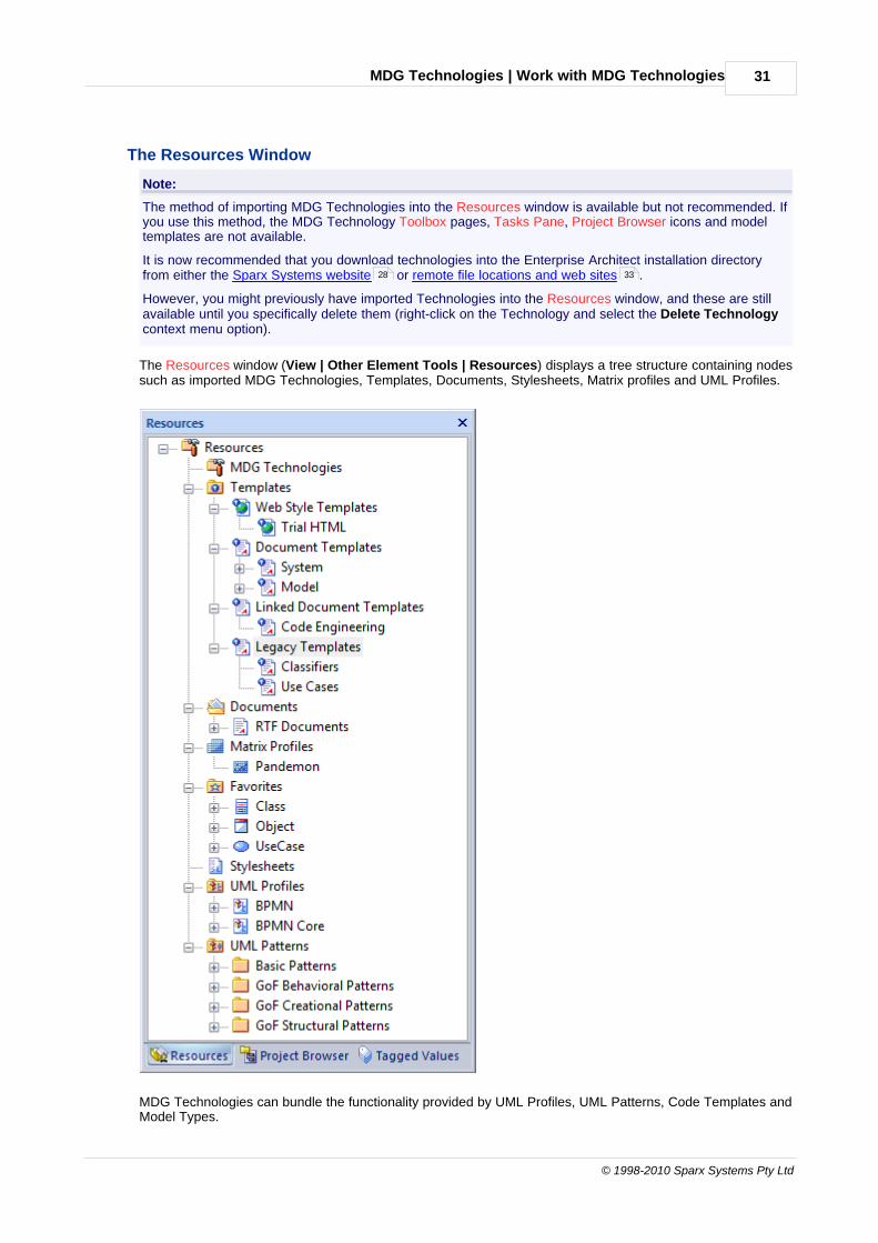
The method of importing MDG Technologies into the Resources window is available but not recommended. Ifyou use this method, the MDG Technology Toolbox pages, Tasks Pane, Project Browser icons and modeltemplates are not available.
It is now recommended that you download technologies into the Enterprise Architect installation directoryfrom either the Sparx Systems website or remote file locations and web sites .
However, you might previously have imported Technologies into the Resources window, and these are stillavailable until you specifically delete them (right-click on the Technology and select the Delete Technologycontext menu option).
The Resources window (View | Other Element Tools | Resources) displays a tree structure containing nodessuch as imported MDG Technologies, Templates, Documents, Stylesheets, Matrix profiles and UML Profiles.
MDG Technologies can bundle the functionality provided by UML Profiles, UML Patterns, Code Templates andModel Types.
28 33

MDG Technologies | Work with MDG Technologies32
Extending UML With Enterprise Architect
Profiles contained in MDG Technologies are applied to:
· Elements such as Classes and Interfaces, which are dragged directly from the Enterprise Architect UML Toolbox or the Resources window to the current diagram
· Attributes, which are dragged over a host element (such as a Class) to be automatically added to theelement feature list
· Operations which, like Attributes, are dragged over a host element to add the operation
· Connectors such as Association, Generalization, and Dependency, which are added by selecting them inthe Toolbox or Resources window, then clicking on the source element in a diagram and dragging to thetarget element (in the same way as adding normal connectors); the connector is added with the newstereotype and Tagged Value information
· Association Ends, which are added by dragging the connector end element over the end of an Associationin the diagram.
Patterns contained in MDG Technologies are used to:
· Enable reuse in a model
· Build in robustness.
Code Templates are used to:
· Specify the transformation from UML elements into various parts of a given programming language.
Model Types are used to:
· Define the data types for the model.
4.2.1 Manage MDG Technologies
You use the MDG Technologies dialog to manage the MDG Technologies available and accessible toEnterprise Architect users. To display this dialog, select the Settings | MDG Technologies menu option.
The MDG Technologies dialog lists the technologies held in the Enterprise Architect Install directory, inalphabetical order.
Enable and Disable MDG Technologies
All MDG Technologies listed can be made available (enabled) or removed from use (disabled). To enable ordisable a Technology, click on its Enabled checkbox.
MDG Technologies | Work with MDG Technologies 33
© 1998-2010 Sparx Systems Pty Ltd
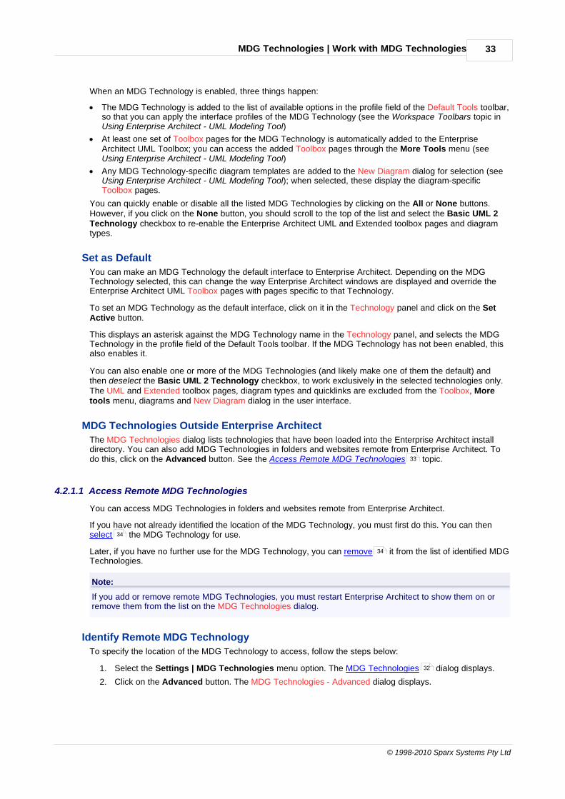
When an MDG Technology is enabled, three things happen:
· The MDG Technology is added to the list of available options in the profile field of the Default Tools toolbar,so that you can apply the interface profiles of the MDG Technology (see the Workspace Toolbars topic inUsing Enterprise Architect - UML Modeling Tool)
· At least one set of Toolbox pages for the MDG Technology is automatically added to the EnterpriseArchitect UML Toolbox; you can access the added Toolbox pages through the More Tools menu (seeUsing Enterprise Architect - UML Modeling Tool)
· Any MDG Technology-specific diagram templates are added to the New Diagram dialog for selection (seeUsing Enterprise Architect - UML Modeling Tool); when selected, these display the diagram-specificToolbox pages.
You can quickly enable or disable all the listed MDG Technologies by clicking on the All or None buttons.However, if you click on the None button, you should scroll to the top of the list and select the Basic UML 2Technology checkbox to re-enable the Enterprise Architect UML and Extended toolbox pages and diagramtypes.
Set as Default
You can make an MDG Technology the default interface to Enterprise Architect. Depending on the MDGTechnology selected, this can change the way Enterprise Architect windows are displayed and override theEnterprise Architect UML Toolbox pages with pages specific to that Technology.
To set an MDG Technology as the default interface, click on it in the Technology panel and click on the SetActive button.
This displays an asterisk against the MDG Technology name in the Technology panel, and selects the MDGTechnology in the profile field of the Default Tools toolbar. If the MDG Technology has not been enabled, thisalso enables it.
You can also enable one or more of the MDG Technologies (and likely make one of them the default) andthen deselect the Basic UML 2 Technology checkbox, to work exclusively in the selected technologies only.The UML and Extended toolbox pages, diagram types and quicklinks are excluded from the Toolbox, Moretools menu, diagrams and New Diagram dialog in the user interface.
MDG Technologies Outside Enterprise Architect
The MDG Technologies dialog lists technologies that have been loaded into the Enterprise Architect installdirectory. You can also add MDG Technologies in folders and websites remote from Enterprise Architect. Todo this, click on the Advanced button. See the Access Remote MDG Technologies topic.
4.2.1.1 Access Remote MDG Technologies
You can access MDG Technologies in folders and websites remote from Enterprise Architect.
If you have not already identified the location of the MDG Technology, you must first do this. You can then select the MDG Technology for use.
Later, if you have no further use for the MDG Technology, you can remove it from the list of identified MDGTechnologies.
Note:
If you add or remove remote MDG Technologies, you must restart Enterprise Architect to show them on orremove them from the list on the MDG Technologies dialog.
Identify Remote MDG Technology
To specify the location of the MDG Technology to access, follow the steps below:
1. Select the Settings | MDG Technologies menu option. The MDG Technologies dialog displays.
2. Click on the Advanced button. The MDG Technologies - Advanced dialog displays.
33
34
34
32
MDG Technologies | Work with MDG Technologies34
Extending UML With Enterprise Architect
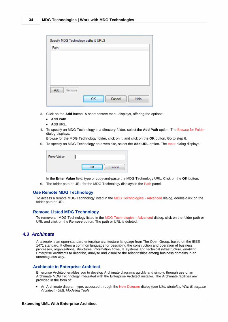
3. Click on the Add button. A short context menu displays, offering the options:
· Add Path
· Add URL.
4. To specify an MDG Technology in a directory folder, select the Add Path option. The Browse for Folderdialog displays.
Browse for the MDG Technology folder, click on it, and click on the OK button. Go to step 6.
5. To specify an MDG Technology on a web site, select the Add URL option. The Input dialog displays.
In the Enter Value field, type or copy-and-paste the MDG Technology URL. Click on the OK button.
6. The folder path or URL for the MDG Technology displays in the Path panel.
Use Remote MDG Technology
To access a remote MDG Technology listed in the MDG Technologies - Advanced dialog, double-click on thefolder path or URL.
Remove Listed MDG Technology
To remove an MDG Technology listed in the MDG Technologies - Advanced dialog, click on the folder path orURL and click on the Remove button. The path or URL is deleted.
4.3 Archimate
Archimate is an open-standard enterprise architecture language from The Open Group, based on the IEEE1471 standard. It offers a common language for describing the construction and operation of businessprocesses, organizational structures, information flows, IT systems and technical infrastructure, enablingEnterprise Architects to describe, analyse and visualize the relationships among business domains in anunambiguous way.
Archimate in Enterprise Architect
Enterprise Architect enables you to develop Archimate diagrams quickly and simply, through use of anArchimate MDG Technology integrated with the Enterprise Architect installer. The Archimate facilities areprovided in the form of:
· An Archimate diagram type, accessed through the New Diagram dialog (see UML Modeling With EnterpriseArchitect - UML Modeling Tool)

MDG Technologies | Archimate 35
© 1998-2010 Sparx Systems Pty Ltd
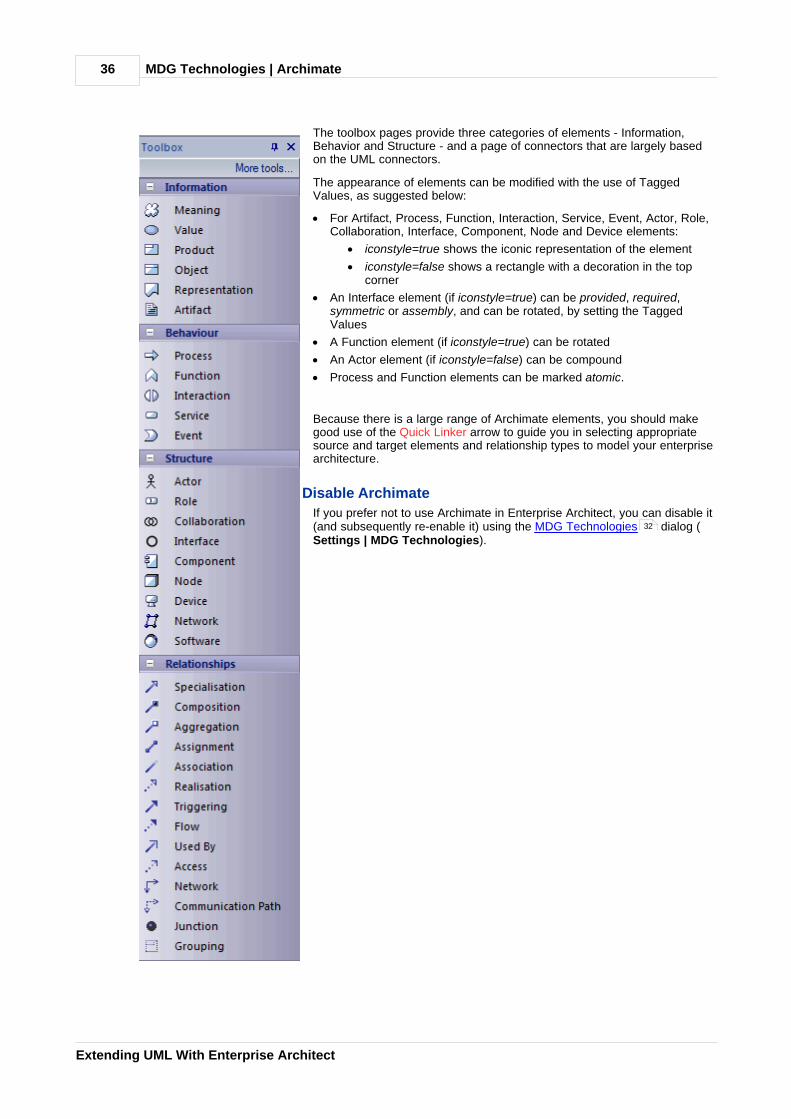
· A set of Archimate pages in the Enterprise Architect UML Toolbox
· Archimate element and relationship entries in the UML Toolbox Shortcut Menu and Quick Linker (seeUsing Enterprise Architect - UML Modeling Tool).
Archimate Toolbox Pages
You can access the Archimate pages of the Toolbox through the More tools | Archimate menu option.
MDG Technologies | Archimate36
Extending UML With Enterprise Architect
The toolbox pages provide three categories of elements - Information,Behavior and Structure - and a page of connectors that are largely basedon the UML connectors.
The appearance of elements can be modified with the use of TaggedValues, as suggested below:
· For Artifact, Process, Function, Interaction, Service, Event, Actor, Role,Collaboration, Interface, Component, Node and Device elements:
· iconstyle=true shows the iconic representation of the element
· iconstyle=false shows a rectangle with a decoration in the topcorner
· An Interface element (if iconstyle=true) can be provided, required,symmetric or assembly, and can be rotated, by setting the TaggedValues
· A Function element (if iconstyle=true) can be rotated
· An Actor element (if iconstyle=false) can be compound
· Process and Function elements can be marked atomic.
Because there is a large range of Archimate elements, you should makegood use of the Quick Linker arrow to guide you in selecting appropriatesource and target elements and relationship types to model your enterprisearchitecture.
Disable Archimate
If you prefer not to use Archimate in Enterprise Architect, you can disable it(and subsequently re-enable it) using the MDG Technologies dialog (Settings | MDG Technologies).
32

MDG Technologies | BPEL 37
© 1998-2010 Sparx Systems Pty Ltd
4.4 BPEL
Note:
Business Process Execution Language (BPEL) is supported in the Business and Software Engineering andUltimate editions of Enterprise Architect.
The following text is derived from the BPEL entry in the online Wikipedia :
Business Process Execution Language (BPEL), short for Web Services Business Process ExecutionLanguage (WS-BPEL), is an executable language for specifying interactions with Web Services.Processes in Business Process Execution Language export and import information by using WebService interfaces exclusively.
Web service interactions can be described in two ways :
1. Executable business processes, which model the actual behavior of a participant in a businessinteraction.
2. Abstract business processes, which are partially specified processes that are not intended to beexecuted. An Abstract Process may hide some of the required concrete operational details.
BPEL is an Orchestration language, serialized in XML, which specifies an executable process thatinvolves message exchanges with other systems. This messaging facility depends on the use of theWeb Services Description Language (WSDL) 1.1 to describe outgoing and incoming messages.
Although there is no standard graphical notation for WS-BPEL, Enterprise Architect uses BPMN version 1.1 asa graphical front-end to capture BPEL 1.1 process descriptions. The BPMN specification includes an informaland partial mapping from BPMN to BPEL 1.1.
For further information on the concepts of BPEL, refer to the Wikipedia item and its linked sources.
BPEL in Enterprise Architect
Enterprise Architect currently supports generating BPEL from executable processes. With the help of theBPMN version 1.1 Profile, Enterprise Architect enables you to develop BPEL diagrams quickly and simply. TheBPEL facilities are provided in the form of:
· A BPEL Model Template in the Select Models dialog (see UML Model Management)
· A BPEL diagram type, accessed through the New Diagram dialog (see UML Modeling With EnterpriseArchitect - UML Modeling Tool)
· A BPEL Process element in the BPMN 1.1 Core Toolbox pages, which acts as a container from whichBPEL can be generated
· Custom dialogs for BPMN elements, highlighting the BPMN Tagged Values relevant to BPEL generation.
BPEL Example Generation
The Enterprise Architect Example file (EAExample.EAP) has a sample BPMN 1.1 model from which BPEL canbe generated. If you have installed Enterprise Architect at the default location, open this file:
C:\Program Files\Sparx Systems\EA\EAExample.EAP
The BPMN model package, within EAExample.EAP, is in: System Model -> Implementation Model (PSM) ->BPEL Example.
Modeling Restrictions
· Use the elements from the BPMN 1.1 Toolbox pages for BPEL modeling.
· Every BPEL Process and Sub-Process should start with a StartEvent and end with an EndEvent.
· A StartEvent or an EndEvent should not be attached to the boundary of a Sub-Process.
· SequenceFlow Looping is not supported - only Activity looping is supported. All SequenceFlows shouldflow downstream and not upstream.
· Mapping of an IntermediateEvent with multiple triggers to BPEL is not supported.
· Mapping of multi-instance parallel While loops to BPEL is not supported.
· Mapping of Independent sub-processes to BPEL is not supported.
67

MDG Technologies | BPEL38
Extending UML With Enterprise Architect
See Also
· Create a BPEL Model
· Model a BPEL Process
· Model a Sequence Flow Connector
· Create Assignments
· Generate BPEL
· Create a BPEL Web Service
· BPEL Model Validation
4.4.1 Create a BPEL Model
You can create a BPEL model from the Project Browser, using the Select Model(s) (Model Wizard) dialog(see UML Model Management).
To display the dialog, use one of the following methods:
· Click on the New Model from Pattern icon in the Project Browser toolbar
· Right-click on a model root node and select the Add a New Model using Wizard context menu option
· Right-click on a package and select the Add | Add a New Model using Wizard context menu option.
The BPEL model pattern is available in the Common catalog (in the Select From field, select Common).
BPEL Package Structure
Notice the BPEL Process (LoanApproval_Process) itself and the supporting components (SupportingElementsand Participant Pools).
38
40
59
61
63
64
65
MDG Technologies | BPEL 39
© 1998-2010 Sparx Systems Pty Ltd
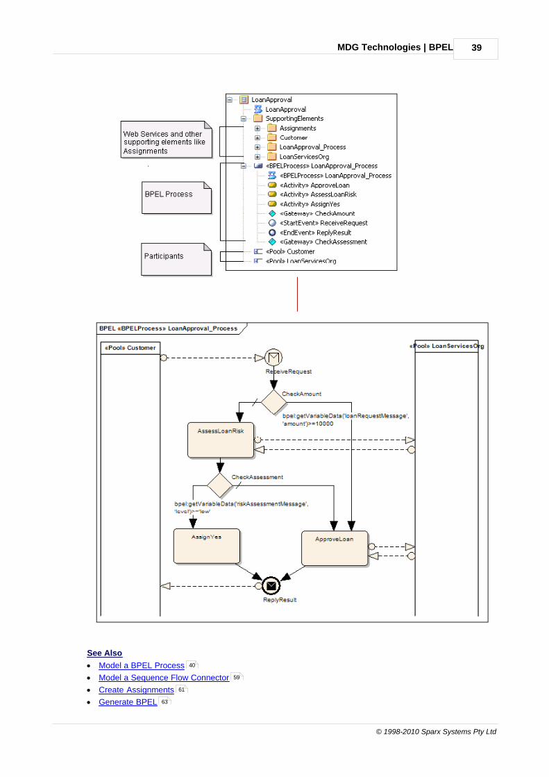
See Also
· Model a BPEL Process
· Model a Sequence Flow Connector
· Create Assignments
· Generate BPEL
40
59
61
63
MDG Technologies | BPEL40
Extending UML With Enterprise Architect
· Create a BPEL Web Service
· BPEL Model Validation
4.4.2 Model a BPEL Process
The BPEL Process in Enterprise Architect represents the top-level container for the BPEL elements, fromwhich BPEL can be generated. Conceptually it maps to the BPEL process element.
To create a BPEL Process in your BPEL model, follow the steps below:
1. Open or create a BPEL diagram.
2. Open the BPMN 1.1 pages of the Enterprise Architect UML Toolbox (More tools | BPMN 1.1).
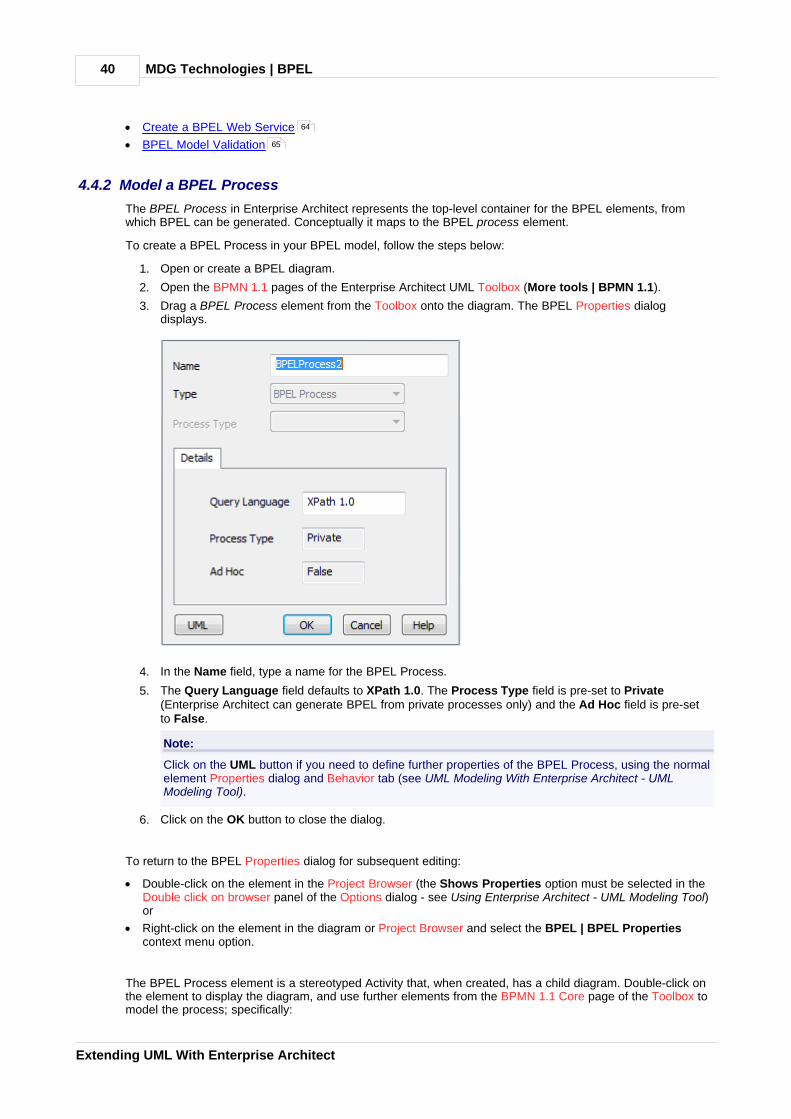
3. Drag a BPEL Process element from the Toolbox onto the diagram. The BPEL Properties dialogdisplays.
4. In the Name field, type a name for the BPEL Process.
5. The Query Language field defaults to XPath 1.0. The Process Type field is pre-set to Private(Enterprise Architect can generate BPEL from private processes only) and the Ad Hoc field is pre-setto False.
Note:
Click on the UML button if you need to define further properties of the BPEL Process, using the normalelement Properties dialog and Behavior tab (see UML Modeling With Enterprise Architect - UMLModeling Tool).
6. Click on the OK button to close the dialog.
To return to the BPEL Properties dialog for subsequent editing:
· Double-click on the element in the Project Browser (the Shows Properties option must be selected in theDouble click on browser panel of the Options dialog - see Using Enterprise Architect - UML Modeling Tool)or
· Right-click on the element in the diagram or Project Browser and select the BPEL | BPEL Propertiescontext menu option.
The BPEL Process element is a stereotyped Activity that, when created, has a child diagram. Double-click onthe element to display the diagram, and use further elements from the BPMN 1.1 Core page of the Toolbox tomodel the process; specifically:
64
65

MDG Technologies | BPEL 41
© 1998-2010 Sparx Systems Pty Ltd
· Start Event
· End Event
· Intermediate Event
· Gateway
· Activity
· Pool .
Note:
On the BPMN 1.1 Core page, the following elements are not mappable to BPEL:
· Pool
· Lane
· Data Object
· Group
· Text Annotation.
See Also
· Create a BPEL Model
· Model a Sequence Flow Connector
· Create Assignments
· Generate BPEL
· Create a BPEL Web Service
· BPEL Model Validation
4.4.2.1 Model Start Event
A Start Event indicates where a particular Process begins. Every Process in Enterprise Architect must beginwith a Start Event.
A Process can start in several ways, depending on the Trigger Type. The OMG BPMN 1.1 Specificationdefines six types of Trigger:
· None
· Message
· Timer
· Conditional
· Signal
· Multiple
In Enterprise Architect, four of these Trigger types can be mapped to BPEL as per the OMG BPMN 1.1Specification:
· Message
· Timer
· Conditional
· Multiple
To create a new Start Event in your model, follow the steps below:
1. Open a BPEL diagram created under a BPEL Process .
2. Drag the Start Event element from the BPMN 1.1 Core page of the Toolbox onto the diagram. A promptdisplays to select either an edge-mounted event (on an element border) or a standalone event.
3. Click on either option. The BPEL Properties dialog displays.
41
44
47
51
53
58
38
59
61
63
64
65
40

MDG Technologies | BPEL42
Extending UML With Enterprise Architect
4. In the Name field, type a name for the Event.
5. Click on the drop-down arrow in the Trigger Type field and select the required type.
Depending on the trigger type you select, further details might be required.
If you select Timer:
6. The Details tab changes as below:
7. In the Time Cycle field, type the value of the time cycle.
8. The Time Date field defaults to today's date. If it is necessary to change the date, click on the checkboxand the drop-down arrow and select a new date from the calendar.
Note:
The Time Cycle and Time Date fields are mutually exclusive, so you can only set one of them.
9. Go to step 10.
If you select Message:
6. The Details tab changes, as below.

MDG Technologies | BPEL 43
© 1998-2010 Sparx Systems Pty Ltd
7. To the right of the Web Service field, click on the [ ... ] button and select a BPEL web service fromthe list.
8. To the right of the Message field, click on the [ ... ] button and select a message from the list of allmessages in the selected web service.
9. Go to step 10.
If you select Conditional:
6. The Details tab changes, as below.
7. To the right of the Condition field, click on the [ ... ] button and select a Condition element from the listof Condition elements created in the Supporting Elements package .
8. Go to step 10.
If you select Multiple:
6. The Details tab changes, as below.
7. To the right of the Events field, click on the [ ... ] button and select further Start Events from the list ofevents in this process that might trigger the process.
8. Go to step 10.
Resume the procedure:
64
38
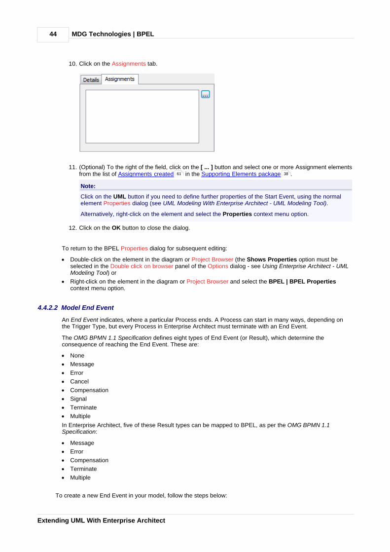
MDG Technologies | BPEL44
Extending UML With Enterprise Architect
10. Click on the Assignments tab.
11. (Optional) To the right of the field, click on the [ ... ] button and select one or more Assignment elementsfrom the list of Assignments created in the Supporting Elements package .
Note:
Click on the UML button if you need to define further properties of the Start Event, using the normalelement Properties dialog (see UML Modeling With Enterprise Architect - UML Modeling Tool).
Alternatively, right-click on the element and select the Properties context menu option.
12. Click on the OK button to close the dialog.
To return to the BPEL Properties dialog for subsequent editing:
· Double-click on the element in the diagram or Project Browser (the Shows Properties option must beselected in the Double click on browser panel of the Options dialog - see Using Enterprise Architect - UMLModeling Tool) or
· Right-click on the element in the diagram or Project Browser and select the BPEL | BPEL Propertiescontext menu option.
4.4.2.2 Model End Event
An End Event indicates, where a particular Process ends. A Process can start in many ways, depending onthe Trigger Type, but every Process in Enterprise Architect must terminate with an End Event.
The OMG BPMN 1.1 Specification defines eight types of End Event (or Result), which determine theconsequence of reaching the End Event. These are:
· None
· Message
· Error
· Cancel
· Compensation
· Signal
· Terminate
· Multiple
In Enterprise Architect, five of these Result types can be mapped to BPEL, as per the OMG BPMN 1.1Specification:
· Message
· Error
· Compensation
· Terminate
· Multiple
To create a new End Event in your model, follow the steps below:
61 38

MDG Technologies | BPEL 45
© 1998-2010 Sparx Systems Pty Ltd
1. Open a BPEL diagram created under a BPEL Process .
2. Drag the End Event element from the BPMN 1.1 Core page of the Toolbox onto the diagram. A promptdisplays to select either an edge-mounted event (on an element border) or a standalone event.
3. Click on either option. The BPEL Properties dialog displays.
4. In the Name field, type a name for the Event.
5. Click on the drop-down arrow in the Result Type field and select the required type.
Depending on the result type you select, further details might be required.
If you select Message:
6. The Details tab changes, as below.
7. To the right of the Web Service field, click on the [ ... ] button and select a BPEL web service fromthe list.
8. To the right of the Message field, click on the [ ... ] button and select a message from the list of allmessages in the selected web service.
9. Go to step 10.
If you select Error:
6. The Details tab changes, as below.
40
64

MDG Technologies | BPEL46
Extending UML With Enterprise Architect
7. In the Error Code field, type the required error code.
8. Go to step 10.
If you select Compensation:
6. The Details tab changes, as below.
7. To the right of the Activity field, click on the [ ... ] button and select an Activity from the list of allActivities in the process.
8. Go to step 10.
If you select Terminate:
6. No action is required on the Details tab. Go to step 10.
If you select Multiple:
6. The Details tab changes, as below.
7. To the right of the Events field, click on the [ ... ] button and select further events from the list of eventsin this process that might terminate the process.
8. Go to step 10.
Resume the procedure:
10. Click on the Assignments tab.

MDG Technologies | BPEL 47
© 1998-2010 Sparx Systems Pty Ltd
11. (Optional) To the right of the field, click on the [ ... ] button and select one or more Assignment elementsfrom the list of Assignments created in the Supporting Elements package .
Note:
Click on the UML button if you need to define further properties of the End Event, using the normalelement Properties dialog (see UML Modeling With Enterprise Architect - UML Modeling Tool).
Alternatively, right-click on the element and select the Properties context menu option.
12. Click on the OK button to close the dialog.
To return to the BPEL Properties dialog for subsequent editing:
· Double-click on the element in the diagram or Project Browser (the Shows Properties option must beselected in the Double click on browser panel of the Options dialog - see Using Enterprise Architect - UMLModeling Tool) or
· Right-click on the element in the diagram or Project Browser and select the BPEL | BPEL Propertiescontext menu option.
4.4.2.3 Model Intermediate Event
An Intermediate Event indicates where an event occurs somewhere between the start and end of a process.
The OMG BPMN 1.1 Specification defines ten types of Intermediate Event (or Trigger). These are:
· None
· Message
· Timer
· Error
· Cancel
· Compensation
· Conditional
· Link
· Signal
· Multiple
In Enterprise Architect, six of these Trigger types can be mapped to BPEL.
· Message
· Timer
· Error
· Compensation
· Conditional
· Link (but not if the Intermediate Event is edge-mounted on an Activity).
To create a new Intermediate Event in your model, follow the steps below:
1. Open a BPEL diagram created under a BPEL Process .
2. Drag the Intermediate Event element from the BPMN 1.1 Core page of the Toolbox onto the diagram. A
61 38
40

MDG Technologies | BPEL48
Extending UML With Enterprise Architect
prompt displays to select either an edge-mounted event (on an element border) or a standalone event.
Note:
When an Intermediate Event is created as a standalone event, it must have one incoming and oneoutgoing SequenceFlow (except for a Link Intermediate Event, which can have either incoming oroutgoing SequenceFlows, but not both).
3. Click on either option. The BPEL Properties dialog displays.
4. In the Name field, type a name for the Event.
5. Click on the drop-down arrow in the Trigger Type field and select the required type.
Depending on the trigger type you select, further details might be required.
If you select Message:
6. To the right of the Web Service field, click on the [ ... ] button and select a BPEL web service fromthe list.
7. To the right of the Message field, click on the [ ... ] button and select a message from the list of allmessages in the selected web service.
8. Go to step 11.
If you select Error:
6. The Details tab changes, as below.
7. In the Error Code field, type the required error code.
8. Go to step 11.
50
64
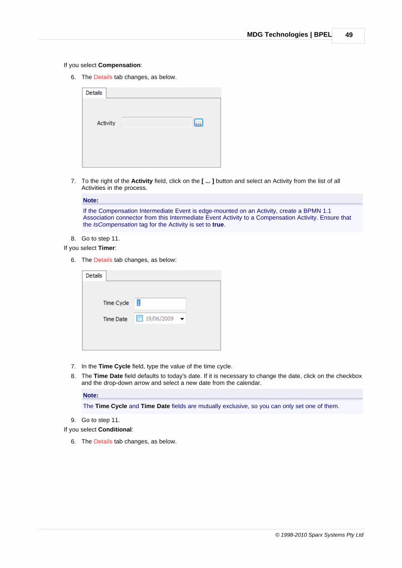
MDG Technologies | BPEL 49
© 1998-2010 Sparx Systems Pty Ltd
If you select Compensation:
6. The Details tab changes, as below.
7. To the right of the Activity field, click on the [ ... ] button and select an Activity from the list of allActivities in the process.
Note:
If the Compensation Intermediate Event is edge-mounted on an Activity, create a BPMN 1.1Association connector from this Intermediate Event Activity to a Compensation Activity. Ensure thatthe IsCompensation tag for the Activity is set to true.
8. Go to step 11.
If you select Timer:
6. The Details tab changes, as below:
7. In the Time Cycle field, type the value of the time cycle.
8. The Time Date field defaults to today's date. If it is necessary to change the date, click on the checkboxand the drop-down arrow and select a new date from the calendar.
Note:
The Time Cycle and Time Date fields are mutually exclusive, so you can only set one of them.
9. Go to step 11.
If you select Conditional:
6. The Details tab changes, as below.

MDG Technologies | BPEL50
Extending UML With Enterprise Architect
7. To the right of the Condition field, click on the [ ... ] button and select an element from the list ofCondition elements created in the Supporting Elements package .
8. Go to step 11.
If you select Link:
6. The Details tab changes, as below.
Note:
A Link Intermediate Event can be used as either a GoTo or an Off-page connector. Therefore thisEvent can have either incoming or outgoing Sequence Flows, but not both.
7. Close the dialog, and drag a Sequence Flow connector from the Toolbox to create a connector eitherfrom or to the appropriate Activity element.
8. If you have created an outgoing Sequence Flow from the Event to an Activity, no further details arerequired.
9. If you have created an incoming Sequence Flow to the Event from an Activity, right-click on the Eventand select the BPEL | BPEL Properties context menu option. The BPEL dialog redisplays as shownbelow:
10. To the right of the Link Event field, click on the [ ... ] button and select the target Link IntermediateEvent from the list.
Resume the procedure:
38

MDG Technologies | BPEL 51
© 1998-2010 Sparx Systems Pty Ltd
Note:
Click on the UML button if you have to define further properties of the Intermediate Event, using thenormal element Properties dialog (see UML Modeling With Enterprise Architect - UML Modeling Tool).
Alternatively, right-click on the element and select the Properties context menu option.
11. Click on the OK button to close the dialog.
To return to the BPEL Properties dialog for subsequent editing:
· Double-click on the element in the diagram or Project Browser (the Shows Properties option must beselected in the Double click on browser panel of the Options dialog - see Using Enterprise Architect - UMLModeling Tool) or
· Right-click on the element in the diagram or Project Browser and select the BPEL | BPEL Propertiescontext menu option.
4.4.2.4 Model Gateway
Gateways control the way in which Sequence Flows converge and diverge within a Process. They providea gating mechanism that either allows or blocks a Sequence Flow.
The OMG BPMN 1.1 Specification describes four types of Gateways:
· Exclusive (XOR)
· Inclusive (OR)
· Complex
· Parallel (AND)
In Enterprise Architect, three of these Gateway types can be mapped to BPEL, as per the OMG BPMN 1.1Specification:
· Exclusive (XOR)
· Inclusive (OR)
· Parallel (AND)
Exclusive Gateway
An Exclusive Gateway represents a 'fork in the road'; that is, there can be two or more alternative paths butonly one can be taken. Therefore, each path is mutually exclusive (XOR). Exclusive Gateways can be one oftwo types:
· Data-Based
· Event-Based
Data-Based Exclusive Gateway
This is the commonest type of Exclusive Gateway, where the boolean expression set in the ConditionExpression Tagged Value of the outgoing Sequence Flow is evaluated to determine the flow path. InEnterprise Architect:
· One of the outgoing Sequence Flows from the Gateway must have the ConditionType tag set to Defaultand the ConditionExpression tag set to empty
· All other Sequence Flows must have the ConditionType tag set to Expression and the ConditionExpressiontag set to a boolean expression.
The Default condition on an outgoing Sequence Flow ensures that at least this path is taken if all othersevaluate to false.
Event-Based Exclusive Gateway
On this Gateway, the branching is based on the events (such as receiving a message) that occur at that pointin the Process, rather than the evaluation of an expression. As an example (from the OMG BPMN 1.1Specification), when a company receives a response from a customer, they perform one set of activities if thecustomer responds Yes and another set of activities if the customer responds No. The customer’s responsedetermines which path is taken. This Gateway maps to a BPEL Pick element. When modeling this Gateway:
· The outgoing Sequence Flow must have its ConditionType tag set to None
59

MDG Technologies | BPEL52
Extending UML With Enterprise Architect
· The target of the outgoing Sequence Flow must be either an:
· Activity with TaskType tag set to Receive, or
· Intermediate Event with Trigger set to Message or Timer.
Note:
If an Activity is the target of one outgoing Sequence Flow, then the Intermediate Event with a Message trigger must not be used.
Inclusive Gateway (OR)
With this type of Gateway, all the outgoing Sequence Flows with a condition that evaluates to true are taken.In Enterprise Architect:
· One of the outgoing Sequence Flows from the Gateway must have the ConditionType tag set to defaultand the ConditionExpression tag set to empty
· All other Sequence Flows must have the ConditionType tag set to Expression and the ConditionExpressiontag set to a boolean expression.
The Default condition on an outgoing Sequence Flow ensures that at least this path is taken if all othersevaluate to false.
Parallel Gateway (AND)
This Gateway provides a mechanism to create parallel flows. In Enterprise Architect, the ConditionType tag onall the outgoing Sequence Flows from this Gateway must be set to None.
Create Gateway
To create a new Gateway element in your model, follow the steps below.
1. Open a BPEL diagram created under a BPEL Process .
2. Drag the Gateway element from the BPMN 1.1 Core page of the Toolbox onto the diagram. The BPELProperties dialog displays.
3. In the Name field, type a name for the Gateway.
4. Click on the drop-down arrow in the Gateway field and select the required type.
5. If you have selected Inclusive or Parallel, no further details are required.
6. If you have selected Exclusive, in the Exclusive Type field click on the drop-down arrow and select thesub-type - Data or Event.
7. If you have selected the sub-type Event, in the Instantiate field click on the drop-down arrow and select
40
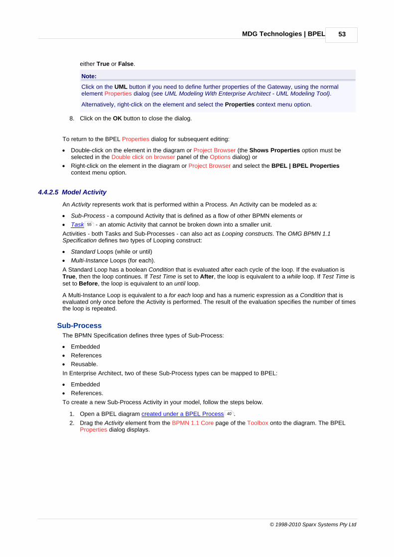
MDG Technologies | BPEL 53
© 1998-2010 Sparx Systems Pty Ltd
either True or False.
Note:
Click on the UML button if you need to define further properties of the Gateway, using the normalelement Properties dialog (see UML Modeling With Enterprise Architect - UML Modeling Tool).
Alternatively, right-click on the element and select the Properties context menu option.
8. Click on the OK button to close the dialog.
To return to the BPEL Properties dialog for subsequent editing:
· Double-click on the element in the diagram or Project Browser (the Shows Properties option must beselected in the Double click on browser panel of the Options dialog) or
· Right-click on the element in the diagram or Project Browser and select the BPEL | BPEL Propertiescontext menu option.
4.4.2.5 Model Activity
An Activity represents work that is performed within a Process. An Activity can be modeled as a:
· Sub-Process - a compound Activity that is defined as a flow of other BPMN elements or
· Task - an atomic Activity that cannot be broken down into a smaller unit.
Activities - both Tasks and Sub-Processes - can also act as Looping constructs. The OMG BPMN 1.1Specification defines two types of Looping construct:
· Standard Loops (while or until)
· Multi-Instance Loops (for each).
A Standard Loop has a boolean Condition that is evaluated after each cycle of the loop. If the evaluation isTrue, then the loop continues. If Test Time is set to After, the loop is equivalent to a while loop. If Test Time isset to Before, the loop is equivalent to an until loop.
A Multi-Instance Loop is equivalent to a for each loop and has a numeric expression as a Condition that isevaluated only once before the Activity is performed. The result of the evaluation specifies the number of timesthe loop is repeated.
Sub-Process
The BPMN Specification defines three types of Sub-Process:
· Embedded
· References
· Reusable.
In Enterprise Architect, two of these Sub-Process types can be mapped to BPEL:
· Embedded
· References.
To create a new Sub-Process Activity in your model, follow the steps below.
1. Open a BPEL diagram created under a BPEL Process .
2. Drag the Activity element from the BPMN 1.1 Core page of the Toolbox onto the diagram. The BPELProperties dialog displays.
55
40

MDG Technologies | BPEL54
Extending UML With Enterprise Architect
3. In the Name field, type a name for the Activity.
4. In the Type field click on the drop-down arrow and select the Sub-Process option.
5. In the Task Type field click on the drop-down arrow and select the Sub Process type - Embedded orReferences.
6. If you select Embedded, you do not have to set any other properties.
7. If you select References, the Details tab displays as follows:
8. To the right of the SubProcess field, click on the [ ... ] button and select a Sub-Process from the list ofall Sub-Processes in the BPEL process.
Note:
Click on the UML button if you need to define further properties of the Activity, using the normalelement Properties dialog (see UML Modeling With Enterprise Architect - UML Modeling Tool).
Alternatively, right-click on the element and select the Properties context menu option.
9. Click on the OK button to close the dialog.
To return to the BPEL Properties dialog for subsequent editing:
· Double-click on the element in the diagram or Project Browser (the Shows Properties option must beselected in the Double click on browser panel of the Options dialog - see Using Enterprise Architect - UMLModeling Tool) or
· Right-click on the element in the diagram or Project Browser and select the BPEL | BPEL Propertiescontext menu option.

MDG Technologies | BPEL 55
© 1998-2010 Sparx Systems Pty Ltd
Task
The OMG BPMN 1.1 Specification defines eight types of Task:
· Service
· User
· Receive
· Send
· Script
· Manual
· Reference
· None.
In Enterprise Architect, six of these Task types can be mapped to BPEL, as per the OMG BPMN 1.1Specification:
· Service
· User
· Receive
· Send
· Reference
· None.
To create a new Task Activity in your model, follow the steps below.
1. Open a BPEL diagram generated under a BPEL Process .
2. Drag the Activity element from the BPMN 1.1 Core page of the Toolbox onto the diagram. The BPELProperties dialog displays.
3. In the Name field, type a name for the Activity.
4. In the Type field click on the drop-down arrow and select the Task option.
5. In the Task Type field click on the drop-down arrow and select the Task type.
Depending on the Task type you select, further details might be required.
If you select None:
6. No further details are required. Go to step 11
If you select Reference:
40

MDG Technologies | BPEL56
Extending UML With Enterprise Architect
6. The Details tab changes, as below.
7. To the right of the Activity field, click on the [ ... ] button and select an Activity from the list of all Tasksin the process.
8. Go to step 11.
If you select Send:
6. The Details tab changes, as below.
7. To the right of the Web Service field, click on the [ ... ] button and select a BPEL web service fromthe list.
8. To the right of the Message field, click on the [ ... ] button and select a message from the list of allmessages in the selected web service.
9. Go to step 11.
If you select Receive:
6. The Details tab changes, as below.
7. To the right of the Web Service field, click on the [ ... ] button and select a BPEL web service fromthe list.
8. To the right of the Message field, click on the [ ... ] button and select a message from the list of allmessages in the selected web service.
9. In the Instantiate field click on the drop-down arrow and select True if this is the first Activity after theStart Event , otherwise select False.
64
64
41
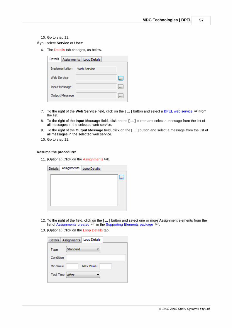
MDG Technologies | BPEL 57
© 1998-2010 Sparx Systems Pty Ltd
10. Go to step 11.
If you select Service or User:
6. The Details tab changes, as below.
7. To the right of the Web Service field, click on the [ ... ] button and select a BPEL web service fromthe list.
8. To the right of the Input Message field, click on the [ ... ] button and select a message from the list ofall messages in the selected web service.
9. To the right of the Output Message field, click on the [ ... ] button and select a message from the list ofall messages in the selected web service.
10. Go to step 11.
Resume the procedure:
11. (Optional) Click on the Assignments tab.
12. To the right of the field, click on the [ ... ] button and select one or more Assignment elements from thelist of Assignments created in the Supporting Elements package .
13. (Optional) Click on the Loop Details tab.
64
61 38

MDG Technologies | BPEL58
Extending UML With Enterprise Architect
14. In the Type field click on the drop-down arrow and select the loop type - Standard or MultiInstance(the field defaults to None).
15. In the Condition field, type the condition to be evaluated (boolean for a Standard loop, numericexpression for a MultiInstance loop).
16. In the Min Value field, type the minimum value for the evaluation.
17. (Standard loop) In the Max Value field type the maximum value for the evaluation.
18. (Standard loop) In the Test Time field click on the drop-down arrow and select After to define a whileloop or Before to define an until loop.
Note:
Click on the UML button if you need to define further properties of the Activity, using the normalelement Properties dialog (see UML Modeling With Enterprise Architect - UML Modeling Tool).
Alternatively, right-click on the element and select the Properties context menu option.
19. Click on the OK button to close the dialog.
To return to the BPEL Properties dialog for subsequent editing:
· Double-click on the element in the diagram or Project Browser (the Shows Properties option must beselected in the Double click on browser panel of the Options dialog - see Using Enterprise Architect - UMLModeling Tool) or
· Right-click on the element in the diagram or Project Browser and select the BPEL | BPEL Propertiescontext menu option.
4.4.2.6 Model Pool
A Pool represents a Participant in a Process and does not map to any specific BPEL element. EnterpriseArchitect uses Pools to represent external Participants, with which the BPEL Process communicates. Theseare 'black box' pools; that is, they are abstract and do not expose any details (they do not contain any BPMNelements inside them).
To create a new Pool in your model, follow the steps below.
1. Open a BPEL diagram created under a BPEL Process .
2. Drag the Pool element from the BPMN 1.1 Core page of the Toolbox onto the diagram. The BPELProperties dialog displays.
38
40

MDG Technologies | BPEL 59
© 1998-2010 Sparx Systems Pty Ltd
3. In the Name field, type a name for the Pool element.
Note:
Click on the UML button if you need to define further properties of the Activity, using the normalelement Properties dialog (see UML Modeling With Enterprise Architect - UML Modeling Tool).
Alternatively, right-click on the element and select the Properties context menu option.
4. Click on the OK button to close the dialog.
To return to the BPEL Properties dialog for subsequent editing:
· Double-click on the element in the diagram or Project Browser (the Shows Properties option must beselected in the Double click on browser panel of the Options dialog - see Using Enterprise Architect - UMLModeling Tool) or
· Right-click on the element in the diagram or Project Browser and select the BPEL | BPEL Propertiescontext menu option.
4.4.3 Model Sequence Flow Connector
A Sequence Flow connector shows the order in which the activities (Tasks and Events) are performed in aBPEL Process.
Create Sequence Flow
To create a new Sequence Flow connector in your model, follow the steps below.
1. Open a BPEL diagram created under a BPEL Process .
2. Click on the Sequence Flow connector from the BPMN 1.1 Relationships page of the Toolbox, then clickon the start element and drag across to the target element on the diagram. Double-click on theconnector to display the Properties dialog.
If the Sequence Flow connector has a non-Gateway element as the start element, the Properties dialogdisplays as shown below:
40
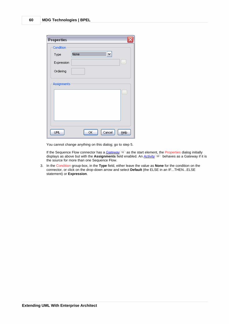
MDG Technologies | BPEL60
Extending UML With Enterprise Architect
You cannot change anything on this dialog; go to step 5.
If the Sequence Flow connector has a Gateway as the start element, the Properties dialog initiallydisplays as above but with the Assignments field enabled. An Activity behaves as a Gateway if it isthe source for more than one Sequence Flow.
3. In the Condition group-box, in the Type field, either leave the value as None for the condition on theconnector, or click on the drop-down arrow and select Default (the ELSE in an IF...THEN...ELSEstatement) or Expression.
51
53
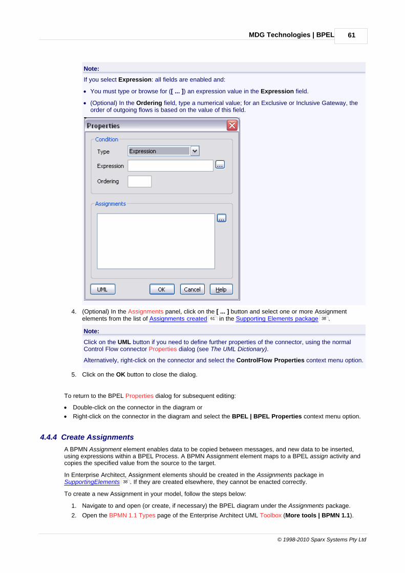
MDG Technologies | BPEL 61
© 1998-2010 Sparx Systems Pty Ltd
Note:
If you select Expression: all fields are enabled and:
· You must type or browse for ([ ... ]) an expression value in the Expression field.
· (Optional) In the Ordering field, type a numerical value; for an Exclusive or Inclusive Gateway, theorder of outgoing flows is based on the value of this field.
4. (Optional) In the Assignments panel, click on the [ ... ] button and select one or more Assignmentelements from the list of Assignments created in the Supporting Elements package .
Note:
Click on the UML button if you need to define further properties of the connector, using the normalControl Flow connector Properties dialog (see The UML Dictionary).
Alternatively, right-click on the connector and select the ControlFlow Properties context menu option.
5. Click on the OK button to close the dialog.
To return to the BPEL Properties dialog for subsequent editing:
· Double-click on the connector in the diagram or
· Right-click on the connector in the diagram and select the BPEL | BPEL Properties context menu option.
4.4.4 Create Assignments
A BPMN Assignment element enables data to be copied between messages, and new data to be inserted,using expressions within a BPEL Process. A BPMN Assignment element maps to a BPEL assign activity andcopies the specified value from the source to the target.
In Enterprise Architect, Assignment elements should be created in the Assignments package inSupportingElements . If they are created elsewhere, they cannot be enacted correctly.
To create a new Assignment in your model, follow the steps below:
1. Navigate to and open (or create, if necessary) the BPEL diagram under the Assignments package.
2. Open the BPMN 1.1 Types page of the Enterprise Architect UML Toolbox (More tools | BPMN 1.1).
61 38
38
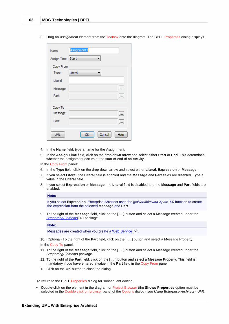
MDG Technologies | BPEL62
Extending UML With Enterprise Architect
3. Drag an Assignment element from the Toolbox onto the diagram. The BPEL Properties dialog displays.
4. In the Name field, type a name for the Assignment.
5. In the Assign Time field, click on the drop-down arrow and select either Start or End. This determineswhether the assignment occurs at the start or end of an Activity.
In the Copy From panel:
6. In the Type field, click on the drop-down arrow and select either Literal, Expression or Message.
7. If you select Literal, the Literal field is enabled and the Message and Part fields are disabled. Type avalue in the Literal field.
8. If you select Expression or Message, the Literal field is disabled and the Message and Part fields areenabled.
Note:
If you select Expression, Enterprise Architect uses the getVariableData Xpath 1.0 function to createthe expression from the selected Message and Part.
9. To the right of the Message field, click on the [ ... ] button and select a Message created under theSupportingElements package.
Note:
Messages are created when you create a Web Service .
10. (Optional) To the right of the Part field, click on the [ ... ] button and select a Message Property.
In the Copy To panel:
11. To the right of the Message field, click on the [ ... ] button and select a Message created under theSupportingElements package.
12. To the right of the Part field, click on the [ ... ] button and select a Message Property. This field ismandatory if you have entered a value in the Part field in the Copy From panel.
13. Click on the OK button to close the dialog.
To return to the BPEL Properties dialog for subsequent editing:
· Double-click on the element in the diagram or Project Browser (the Shows Properties option must beselected in the Double click on browser panel of the Options dialog - see Using Enterprise Architect - UML
38
64
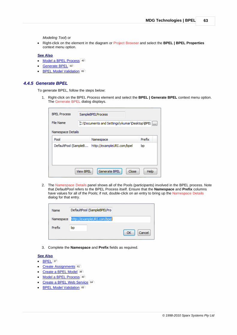
MDG Technologies | BPEL 63
© 1998-2010 Sparx Systems Pty Ltd
Modeling Tool) or
· Right-click on the element in the diagram or Project Browser and select the BPEL | BPEL Propertiescontext menu option.
See Also
· Model a BPEL Process
· Generate BPEL
· BPEL Model Validation
4.4.5 Generate BPEL
To generate BPEL, follow the steps below:
1. Right-click on the BPEL Process element and select the BPEL | Generate BPEL context menu option.The Generate BPEL dialog displays.
2. The Namespace Details panel shows all of the Pools (participants) involved in the BPEL process. Notethat DefaultPool refers to the BPEL Process itself. Ensure that the Namespace and Prefix columnshave values for all of the Pools; if not, double-click on an entry to bring up the Namespace Detailsdialog for that entry.
3. Complete the Namespace and Prefix fields as required.
See Also
· BPEL
· Create Assignments
· Create a BPEL Model
· Model a BPEL Process
· Create a BPEL Web Service
· BPEL Model Validation
40
63
65
37
61
38
40
64
65

MDG Technologies | BPEL64
Extending UML With Enterprise Architect
4.4.6 Create a BPEL Web Service
Enterprise Architect enables you to create, for BPEL Process and Pool elements, Web Services that supporteither synchronous (request-response) or asynchronous (one-way) interactions.
To create a web service, follow the steps below:
1. Right-click on the BPEL Process or Pool element and select the BPEL | Create Web Service contextmenu option. The Create Web Service dialog displays.
2. You can create a Web Service:
· From scratch - select the Create New option in the Web Service field, or
· By importing an existing WSDL into a (for example) SupportingElements package and then selectingthe Create from existing WSDL option in the Web Service field.
Once you enter all the required values, the Web Service is created under the SupportingElements package.
See Also
· BPEL
· Create a BPEL Model
· Create Assignments
· Model a BPEL Process
37
38
61
40

MDG Technologies | BPEL 65
© 1998-2010 Sparx Systems Pty Ltd
· Generate BPEL
· BPEL Model Validation
4.4.7 BPEL Model Validation
You can use the Enterprise Architect Model Validation facility to check the validity of the BPEL model. You canvalidate an entire BPEL Process or a single BPMN element. Note that Enterprise Architect checks for both theUML and the BPEL rules by default. To enable only BPEL rule validation, select only the BPEL Rulescheckbox in the Model Validation Configuration dialog. For further information on Model Validation, see UMLModel Management.
Example Model Violation
The following model shows several basic BPEL violations:
63
65

MDG Technologies | BPEL66
Extending UML With Enterprise Architect
1. StartEvent1 has its trigger set to None, which cannot be mapped to BPEL.
2. EndEvent1 has its trigger set to Cancel, which cannot be mapped to BPEL.
3. EndEvent1 cannot have any outgoing SequenceFlows, as it represents the end of a process.
4. Activity2 has no outgoing SequenceFlows. Enterprise Architect expects only an EndEvent to representthe end of a process.
If you run Model Validation on this diagram, Enterprise Architect lists the violations in the Output window, asshown:
See Also
· BPEL
· Create a BPEL Model
· Create Assignments
· Model a BPEL Process
· Generate BPEL
· Create a BPEL Web Service
37
38
61
40
63
64

MDG Technologies | BPMN 67
© 1998-2010 Sparx Systems Pty Ltd
4.5 BPMN
The following text is derived from the Business Process Modeling Notation entry in the online Wikipedia.
The Business Process Modeling Notation (BPMN) is a standardized graphical notation for drawingbusiness processes in a workflow. BPMN was developed by Business Process Management Initiative(BPMI), and is now being maintained by the Object Management Group since the two organizationsmerged in 2005.
The primary goal of BPMN is to provide a standard notation that is readily understandable by allbusiness stakeholders. These business stakeholders include the business analysts who create andrefine the processes, the technical developers responsible for implementing the processes, and thebusiness managers who monitor and manage the processes. Consequently BPMN is intended to serveas common language to bridge the communication gap that frequently occurs between businessprocess design and implementation.
... The adoption of BPMN standard notation will help unify the expression of basic business processconcepts (e.g. public and private processes, choreographies) as well as advanced modeling concepts(e.g. exception handling, transaction compensation).
BPMN ... supports only the concepts of modeling that are applicable to business processes ... othertypes of modeling done by organizations for non-business purposes [are] out of scope for BPMN. Forexample, ... modeling ... the following is not a part of BPMN:
· Organizational structures
· Functional breakdowns
· Data models
In addition, while BPMN shows the flow of data (messages) and the association of data artifacts toactivities, it is not a data flow diagram.
For further information on the concepts of BPMN, refer to the Wikipedia item and its linked sources.
Note:
The Enterprise Architect installer for releases later than 7.1 provides you with version 1.5 of MDG Technologyfor BPMN, which supports BPMN version 1.1 and BPEL. This enables you to create and maintain diagrams inthe BPMN 1.1 and BPEL formats.
The installer also provides version 1.4.4 of MDG Technology for BPMN, which supports BPMN 1.0. Thisenables you to maintain existing diagrams created in BPMN 1.0 format, and to create new diagrams in BPMN1.0 if you want to maintain consistency through your project.
Enterprise Architect also enables you to migrate a BPMN 1.0 model (or part of a model) to BPMN 1.1 .
BPMN in Enterprise Architect
The BPMN notation is specifically targeted at the business modeling community and has a relatively directmapping to UML through BPMN Profiles integrated with the Enterprise Architect installer. Through use ofthese profiles, Enterprise Architect enables you to develop BPMN diagrams quickly and simply. The BPMNfacilities are provided in the form of:
· A BPMN diagram type, accessed through the New Diagram dialog (see UML Modeling With EnterpriseArchitect - UML Modeling Tool)
· BPMN pages in the Enterprise Architect UML Toolbox
· BPMN element and relationship entries in the UML Toolbox Shortcut Menu and Quick Linker (see UsingEnterprise Architect - UML Modeling Tool).
BPMN Toolbox Pages
You can access the BPMN pages of the Toolbox through the More tools | BPMN 1.0 and BPMN 1.1 menuoptions. These pages provide the graphical (Core) and non-graphical (Types) BPMN elements for use onbusiness process diagrams.
Specifications of these elements and relationships are defined by Tagged Values (for example, to define the Message, Timer and Default Path (/) symbols in the diagram below).
For further information on BPMN and Tagged Values, see the Change BPMN Element Appearance topic.
71
70

MDG Technologies | BPMN68
Extending UML With Enterprise Architect

MDG Technologies | BPMN 69
© 1998-2010 Sparx Systems Pty Ltd
Page Item Use to
Core Business Process Extend a composite Activity that defines a business process.
BPEL Process Define the behavior of an executable or abstract businessprocess.
Activity Define an activity within a business process
Start Event Define the initiating event in a process.
Intermediate Event Define an intermediate event in a process.
End Event Define the terminating event in a process.
Gateway Define a decision point in a business process. If a condition istrue, then processing continues one way; if not, then another.
Pool Extend a Partition element to logically organize an Activity.
Lane Extend a Partition element to subdivide a Pool.
Data Object Extend an Artifact element to define a physical piece ofinformation used or produced by a system.
Group Extend a Boundary element to group other elements.
Text Annotation Create a comment.
Relationships Sequence Flow Extend a Control Flow relationship to define the flow of activity.
Message Flow Extend a Control Flow relationship to define the flow ofcommunications in the process.
Association Associate information and artifacts with flow objects.
Types Assignment

MDG Technologies | BPMN70
Extending UML With Enterprise Architect
Page Item Use to
Condition
Define the properties (Tagged Values) of the Core BPMN 1.1elements such as Activities, Events and Gates.
Message
Participant
Signal
Rule
Transaction
Web Service
Property
Disable BPMN
If you prefer not to use BPMN in Enterprise Architect, you can disable it (and subsequently re-enable it) usingthe MDG Technologies dialog (Settings | MDG Technologies).
4.5.1 Change BPMN Element Appearance
To define the specifications of BPMN elements and relationships, open the Tagged Values window and selectthe required element or relationship in a diagram. The Tagged Values window shows the appropriate TaggedValues and provides a list of values to assign to each one.
Some Tagged Values directly affect the appearance of the elements they apply to, as described in thefollowing examples:
· Events - to change the decoration of a Start Event or Intermediate Event, set the Trigger Tagged Value; tochange the decoration of an End Event, set the Result Tagged Value. For example, to create a BPMN'off-page' connector, set the Trigger or Result Tagged Value to Link to depict flow onto the diagram, into abranch diagram or off the diagram for the Start, Intermediate and End events respectively.
· Gateways - to create the different varieties of Gateway, set the GatewayType Tagged Value; other displayoptions are available for XOR gateways - you can set the XORType Tagged Value to create Event-basedor Data-based XOR gateways, and for Data-based XOR gateways you can set the MarkerVisible TaggedValue to false to hide the decoration.
· Activities - there is a wide variety of appearance options for Activities:
· The ActivityType Tagged Value can be set to Task or Sub-Process; the latter option displays the'plus-in-a-box' decoration on the bottom edge of the shape
· An Ad-hoc Activity is shown by setting the AdHoc Tagged Value to true; this displays the 'tilde'decoration on the bottom edge of the shape
· A Compensation Activity is shown by setting the IsCompensation Tagged Value to true; this displaysthe 'rewind' icon on the bottom edge of the shape
· A Multiple Instance Activity is shown by setting the LoopType Tagged Value to MultiInstance; thisdisplays the 'pause' icon on the bottom edge of the shape
· A Loop Activity is shown by setting the LoopType Tagged Value to either Standard or MultiInstance, this displays the 'loop' icon on the bottom edge of the shape.
· Transactions - to denote a Transaction with a double-lined border, set the IsATransaction TaggedValue to true.
· Sequence Flows - to put a diagonal slash across the line at the source end, set the ConditionType TaggedValue to Default; to put an unfilled diamond-shaped decoration at the source end, set the Tagged Value toExpression.
Version Differences
Some BPMN elements have changed in appearance between BPMN version 1.0 and BPMN version 1.1.
32

MDG Technologies | BPMN 71
© 1998-2010 Sparx Systems Pty Ltd
In Enterprise Architect releases later than 7.1, if you work on a model created in an earlier release, usingBPMN 1.0, existing elements default to their version 1.0 appearance. New elements assume the BPMNversion 1.1 appearance and automatically have a Tagged Value BPMNVersion set to 1.1
If you want a new element to revert to the BPMN version 1.0 appearance, set the Tagged Value to 1.0.Conversely, if you want an older element to assume the BPMN version 1.1 appearance, assign the BPMNVersion Tagged Value to it, with the value 1.1.
4.5.2 Migrate BPMN 1.0 Model to BPMN 1.1
Note:
This facility is available from Release 7.5 of Enterprise Architect.
Enterprise Architect enables you to migrate a BPMN 1.0 model (or part of a model) to BPMN 1.1, using theAutomation Interface function MigrateToBPMN11() (see SDK for Enterprise Architect). This function updatesthe Tagged Values and, if required, stereotypes to BPMN 1.1 for all elements, attributes, connectors anddiagrams under the selected package or element.
Warning:
In BPMN 1.0, various tags have free-text direct-entry value fields, and you can provide additional informationon these tags in the Tagged Value Note dialog for display at the bottom of the Tagged Values window.
In BPMN 1.1, some of these tags (such as the Categories tag on a BusinessProcess stereotyped element)have been changed to memo type, and you use the Tagged Value Note dialog to enter the value; therefore,you cannot have additional notes for these tags, all information must be within the tag's value.
For such tags, when migrating from BPMN 1.0 to BPMN 1.1, the BPMN 1.0 tag value is moved into the BPMN1.1 tag notes field and the BPMN 1.0 tag notes are discarded. If you want to preserve the tag notes text, takea copy of the BPMN 1.0 model before migration to enable you to copy the tag notes text into the tag valueafter migration.
The following VB script calls the MigrateToBPMN11() function to migrate the Tagged Values to BPMN 1.1:
Sub MigrateElement (sGUID, lngPackageID)
Dim proj as EA.Projectset proj = Repository.GetProjectInterfaceproj.MigrateToBPMN11 sGUID, "BPMN"
'refresh the modelIf lngPackageID<>0 Then
Repository.RefreshModelView (lngPackageID)End If
End Sub
Sub MigrateSelectedItem
Dim selTypeDim selElement as EA.ElementDim selPackage as EA.Package
selType = GetTreeSelectedItemType
If selType = 4 Then 'means Elementset selElement = GetTreeSelectedObjectMigrateElement selElement.ElementGUID, selElement.PackageIDMsgBox "Complete",0,"BPMN 1.1 Migration"
ElseIf selType = 5 Then 'means Packageset selPackage = GetTreeSelectedObjectMigrateElement selPackage.PackageGUID, selPackage.PackageIDMsgBox "Complete",0,"BPMN 1.1 Migration"
Else

MDG Technologies | BPMN72
Extending UML With Enterprise Architect
MsgBox "Select a Package or Element in the Project Browser to initiate migration",0,"BPMN 1.1 Migration"
End If
End Sub
Sub Main
MigrateSelectedItem
End Sub
Main
4.6 Data Flow Diagrams
The following text is derived from the Data Flow Diagram entry in the online Wikipedia.
A data flow diagram (DFD) is a graphical representation of the "flow" of data through an informationsystem. A data flow diagram can also be used for the visualization of data processing (structureddesign). It is common practice for a designer to draw a context-level DFD first which shows theinteraction between the system and outside entities. This context-level DFD is then "exploded" to showmore detail of the system being modeled.
Data flow diagrams were invented by Larry Constantine ... based on Martin and Estrin's "data flowgraph" model of computation. [They] are one of the three essential perspectives of Structured SystemsAnalysis and Design Method SSADM. The sponsor of a project and the end users will need to bebriefed and consulted throughout all stages of a system's evolution. With a dataflow diagram, users areable to visualize how the system will operate, what the system will accomplish, and how the system willbe implemented. The old system's dataflow diagrams can be drawn up and compared with the newsystem's dataflow diagrams to draw comparisons to implement a more efficient system.
Developing a DFD helps in identifying the transaction data in the data model.
For further information on the concepts of Data Flow Diagrams, refer to the Wikipedia item and its linkedsources.
Data Flow Diagrams in Enterprise Architect
Enterprise Architect enables you to develop Data Flow diagrams quickly and simply, through use of an MDGTechnology integrated with the Enterprise Architect installer. The Data Flow diagram facilities are provided inthe form of:
· A Data Flow diagram type, accessed through the New Diagram dialog (see UML Modeling With EnterpriseArchitect - UML Modeling Tool)
· A Data Flow Diagram page in the Enterprise Architect UML Toolbox
· Data Flow element and relationship entries in the UML Toolbox Shortcut Menu and Quick Linker (seeUsing Enterprise Architect - UML Modeling Tool).
Data Flow Diagram Toolbox Page
You can access the Data Flow Diagram page of the Toolbox through the More tools | Data Flow Diagramsmenu option. The following icons are available:
· Process is a process or activity in which data is used or generated
· External represents an external source, user or depository of the data
· Data Store represents an internal physical or electronic repository of data, into and out of which data is
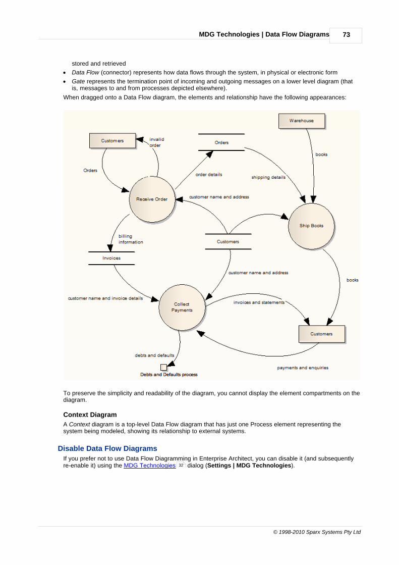
MDG Technologies | Data Flow Diagrams 73
© 1998-2010 Sparx Systems Pty Ltd
stored and retrieved
· Data Flow (connector) represents how data flows through the system, in physical or electronic form
· Gate represents the termination point of incoming and outgoing messages on a lower level diagram (thatis, messages to and from processes depicted elsewhere).
When dragged onto a Data Flow diagram, the elements and relationship have the following appearances:
To preserve the simplicity and readability of the diagram, you cannot display the element compartments on thediagram.
Context Diagram
A Context diagram is a top-level Data Flow diagram that has just one Process element representing thesystem being modeled, showing its relationship to external systems.
Disable Data Flow Diagrams
If you prefer not to use Data Flow Diagramming in Enterprise Architect, you can disable it (and subsequentlyre-enable it) using the MDG Technologies dialog (Settings | MDG Technologies).32
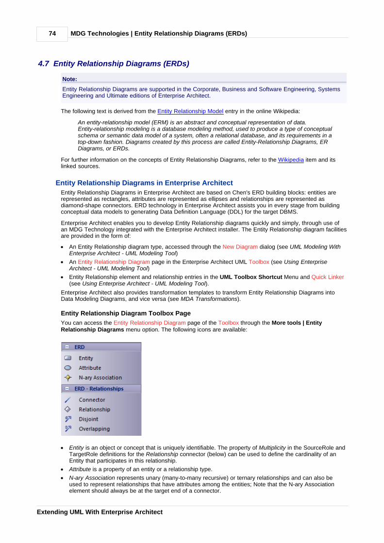
MDG Technologies | Entity Relationship Diagrams (ERDs)74
Extending UML With Enterprise Architect
4.7 Entity Relationship Diagrams (ERDs)
Note:
Entity Relationship Diagrams are supported in the Corporate, Business and Software Engineering, SystemsEngineering and Ultimate editions of Enterprise Architect.
The following text is derived from the Entity Relationship Model entry in the online Wikipedia:
An entity-relationship model (ERM) is an abstract and conceptual representation of data.Entity-relationship modeling is a database modeling method, used to produce a type of conceptualschema or semantic data model of a system, often a relational database, and its requirements in atop-down fashion. Diagrams created by this process are called Entity-Relationship Diagrams, ERDiagrams, or ERDs.
For further information on the concepts of Entity Relationship Diagrams, refer to the Wikipedia item and itslinked sources.
Entity Relationship Diagrams in Enterprise Architect
Entity Relationship Diagrams in Enterprise Architect are based on Chen's ERD building blocks: entities arerepresented as rectangles, attributes are represented as ellipses and relationships are represented asdiamond-shape connectors. ERD technology in Enterprise Architect assists you in every stage from buildingconceptual data models to generating Data Definition Language (DDL) for the target DBMS.
Enterprise Architect enables you to develop Entity Relationship diagrams quickly and simply, through use ofan MDG Technology integrated with the Enterprise Architect installer. The Entity Relationship diagram facilitiesare provided in the form of:
· An Entity Relationship diagram type, accessed through the New Diagram dialog (see UML Modeling WithEnterprise Architect - UML Modeling Tool)
· An Entity Relationship Diagram page in the Enterprise Architect UML Toolbox (see Using EnterpriseArchitect - UML Modeling Tool)
· Entity Relationship element and relationship entries in the UML Toolbox Shortcut Menu and Quick Linker(see Using Enterprise Architect - UML Modeling Tool).
Enterprise Architect also provides transformation templates to transform Entity Relationship Diagrams intoData Modeling Diagrams, and vice versa (see MDA Transformations).
Entity Relationship Diagram Toolbox Page
You can access the Entity Relationship Diagram page of the Toolbox through the More tools | EntityRelationship Diagrams menu option. The following icons are available:
· Entity is an object or concept that is uniquely identifiable. The property of Multiplicity in the SourceRole andTargetRole definitions for the Relationship connector (below) can be used to define the cardinality of anEntity that participates in this relationship.
· Attribute is a property of an entity or a relationship type.
· N-ary Association represents unary (many-to-many recursive) or ternary relationships and can also beused to represent relationships that have attributes among the entities; Note that the N-ary Associationelement should always be at the target end of a connector.
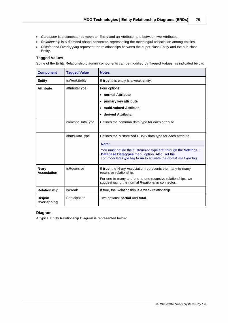
MDG Technologies | Entity Relationship Diagrams (ERDs) 75
© 1998-2010 Sparx Systems Pty Ltd
· Connector is a connector between an Entity and an Attribute, and between two Attributes.
· Relationship is a diamond-shape connector, representing the meaningful association among entities.
· Disjoint and Overlapping represent the relationships between the super-class Entity and the sub-classEntity.
Tagged Values
Some of the Entity Relationship diagram components can be modified by Tagged Values, as indicated below:
Component Tagged Value Notes
Entity isWeakEntity If true, this entity is a weak entity.
Attribute attributeType Four options:
· normal Attribute
· primary key attribute
· multi-valued Attribute
· derived Attribute.
commonDataType Defines the common data type for each attribute.
dbmsDataType Defines the customized DBMS data type for each attribute.
Note:
You must define the customized type first through the Settings |Database Datatypes menu option. Also, set thecommonDataType tag to na to activate the dbmsDataType tag.
N-aryAssociation
isRecursive If true, the N-ary Association represents the many-to-manyrecursive relationship.
For one-to-many and one-to-one recursive relationships, wesuggest using the normal Relationship connector.
Relationship isWeak If true, the Relationship is a weak relationship.
DisjoinOverlapping
Participation Two options: partial and total.
Diagram
A typical Entity Relationship Diagram is represented below:
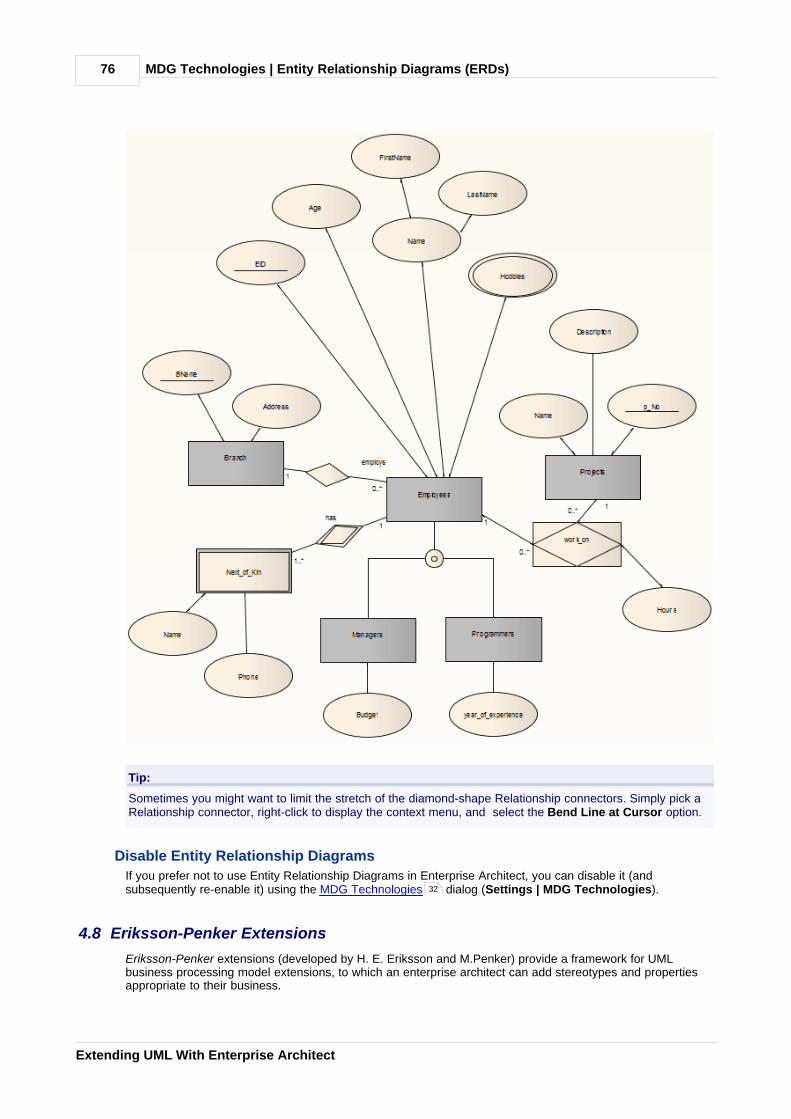
MDG Technologies | Entity Relationship Diagrams (ERDs)76
Extending UML With Enterprise Architect
Tip:
Sometimes you might want to limit the stretch of the diamond-shape Relationship connectors. Simply pick aRelationship connector, right-click to display the context menu, and select the Bend Line at Cursor option.
Disable Entity Relationship Diagrams
If you prefer not to use Entity Relationship Diagrams in Enterprise Architect, you can disable it (andsubsequently re-enable it) using the MDG Technologies dialog (Settings | MDG Technologies).
4.8 Eriksson-Penker Extensions
Eriksson-Penker extensions (developed by H. E. Eriksson and M.Penker) provide a framework for UMLbusiness processing model extensions, to which an enterprise architect can add stereotypes and propertiesappropriate to their business.
32

MDG Technologies | Eriksson-Penker Extensions 77
© 1998-2010 Sparx Systems Pty Ltd
Eriksson-Penker in Enterprise Architect
Enterprise Architect provides - through the integration of MDG Technologies with the installer - twowell-respected and proven UML extensions that further enhance the capture of business activities, processes,objects and information flows. One of these is Business Process Modeling Notation (BPMN). The other isthe Eriksson-Penker profile which, through a set of stereotypes, provides a unique and powerful means ofvisualizing and communicating business processes and the necessary flow of information within anorganization.
The Eriksson-Penker extensions are provided in the form of:
· An Eriksson-Penker diagram type, accessed through the New Diagram dialog (see UML Modeling WithEnterprise Architect - UML Modeling Tool)
· An Eriksson-Penker page in the Enterprise Architect UML Toolbox
· Eriksson-Penker element and relationship entries in the UML Toolbox Shortcut Menu and Quick Linker(see Using Enterprise Architect - UML Modeling Tool).
Eriksson-Penker Toolbox Page
You can access the Eriksson-Penker page of the Toolbox through the More tools | Eriksson-PenkerExtensions menu option. The following icons are available:
67

MDG Technologies | Eriksson-Penker Extensions78
Extending UML With Enterprise Architect
The following is an example of a simple Eriksson-Penker diagram:

MDG Technologies | Eriksson-Penker Extensions 79
© 1998-2010 Sparx Systems Pty Ltd
For further information on the MDG Technology for Eriksson-Penker Extensions, see The Business ProcessModel tutorial.
4.9 GoF Patterns
The following text is derived from the Design Patterns entry in the online Wikipedia.
Gang of Four (GoF) Patterns are 23 classic software design patterns providing recurring solutions tocommon problems in software design. They were developed by Erich Gamma, Richard Helm, RalphJohnson and John Vlissides, often referred to as the Gang of Four. The patterns are defined in thebook Design Patterns: Elements of Reusable Object-Oriented Software (Gamma et al., ISBN0-201-63361-2).
For further information on the concepts of GoF Patterns, refer to the Wikipedia item and its linked sources.
GoF Patterns in Enterprise Architect
Enterprise Architect enables you to develop diagrams from GoF patterns quickly and simply, through use of anMDG Technology integrated with the Enterprise Architect installer. The GoF Patterns are provided in the formof:
· GoF Behavioral Patterns, GoF Creational Patterns and GoF Structural Patterns pages in the EnterpriseArchitect UML Toolbox
· Gang of Four pattern entries in the UML Toolbox Shortcut Menu (see Using Enterprise Architect - UMLModeling Tool).
GoF Toolbox Pages
You can access the GoF Pattern pages of the Toolbox through the More tools | GoF Patterns menu option.The following icons are available:
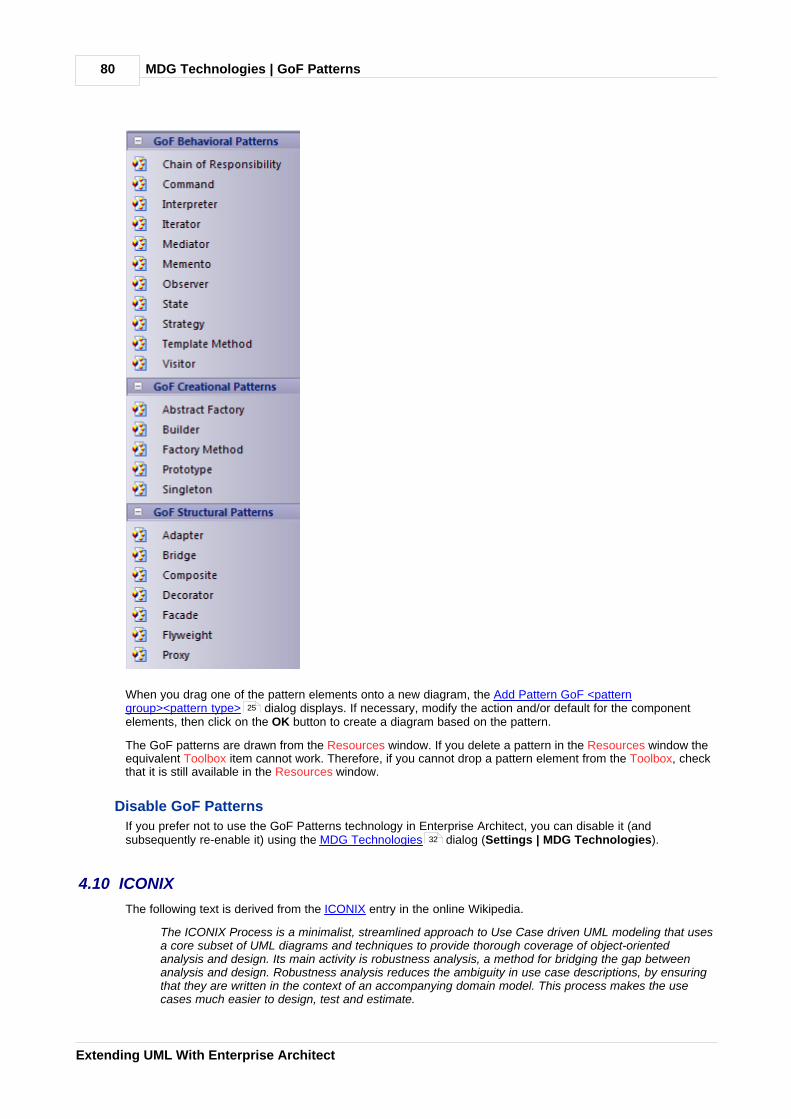
MDG Technologies | GoF Patterns80
Extending UML With Enterprise Architect
When you drag one of the pattern elements onto a new diagram, the Add Pattern GoF <patterngroup><pattern type> dialog displays. If necessary, modify the action and/or default for the componentelements, then click on the OK button to create a diagram based on the pattern.
The GoF patterns are drawn from the Resources window. If you delete a pattern in the Resources window theequivalent Toolbox item cannot work. Therefore, if you cannot drop a pattern element from the Toolbox, checkthat it is still available in the Resources window.
Disable GoF Patterns
If you prefer not to use the GoF Patterns technology in Enterprise Architect, you can disable it (andsubsequently re-enable it) using the MDG Technologies dialog (Settings | MDG Technologies).
4.10 ICONIX
The following text is derived from the ICONIX entry in the online Wikipedia.
The ICONIX Process is a minimalist, streamlined approach to Use Case driven UML modeling that usesa core subset of UML diagrams and techniques to provide thorough coverage of object-orientedanalysis and design. Its main activity is robustness analysis, a method for bridging the gap betweenanalysis and design. Robustness analysis reduces the ambiguity in use case descriptions, by ensuringthat they are written in the context of an accompanying domain model. This process makes the usecases much easier to design, test and estimate.
25
32

MDG Technologies | ICONIX 81
© 1998-2010 Sparx Systems Pty Ltd
The ICONIX Process was developed by Doug Rosenberg. For more information on ICONIX, see the ICONIXSoftware Engineering Inc. website http://www.iconixsw.com/.
ICONIX in Enterprise Architect
Enterprise Architect enables you to develop models under ICONIX quickly and simply, through use of an MDGTechnology integrated with the Enterprise Architect installer. The ICONIX facilities are provided in the form of:
· A set of ICONIX pages in the Enterprise Architect UML Toolbox
· ICONIX element and relationship entries in the UML Toolbox Shortcut Menu and Quick Linker (see UsingEnterprise Architect - UML Modeling Tool).
To further help you develop and manage a project under ICONIX, Enterprise Architect also provides a whitepaper on the ICONIX Roadmap.
In addition, Enterprise Architect has an alternative visual layout specific to ICONIX.
ICONIX Toolbox Pages
Within the Toolbox, Enterprise Architect provides ICONIX versions of the pages for UML Analysis, Use Case,Class, Interaction (Sequence), Activity and Custom diagrams (which often form the basis for Robustnessdiagrams) (see the UML Dictionary). Compared to the standard Enterprise Architect Toolbox pages, thesehave slightly different element and relationship sets. You can access them by either:
· Selecting the More tools | ICONIX | <Diagram Type> menu option for a specific Toolbox page, or
· Selecting the ICONIX option in the drop-down field of the Default Tools toolbar, which adds all six pages tothe Toolbox. The first page and the Common page are expanded, and the others are closed up.
82

MDG Technologies | ICONIX82
Extending UML With Enterprise Architect
ICONIX Layout
The ICONIX layout re-organizes the Enterprise Architect work area, opening the:
· Toolbox on the right hand side of the screen (follow the instructions above to display the ICONIX pages)
· The Tasks Pane window auto-hidden in the top right of the screen
· Project Browser window in the top left of the screen, and
· Notes, Properties and Tagged Values windows nested on the bottom left of the screen.

MDG Technologies | ICONIX 83
© 1998-2010 Sparx Systems Pty Ltd
To apply this layout, select the View | Workspace Layouts menu option and select the Basic Layout(Alternate) option (see Using Enterprise Architect - UML Modeling Tool).
Disable ICONIX
If you prefer not to use ICONIX in Enterprise Architect, you can disable it (and subsequently re-enable it) usingthe MDG Technologies dialog (Settings | MDG Technologies).
This does not affect the ICONIX layout, which you can switch back to your own layout or the EnterpriseArchitect default layout using the View | Workspace Layouts menu option.
4.11 Mind Mapping
The following text is derived from the Mind Map entry in the online Wikipedia.
A Mind Map is a diagram used to represent words, ideas, tasks or other items linked to and arrangedradially around a central key word or idea. It is used to generate, visualize, structure and classify ideas,and as an aid in study, organization, problem solving, decision making, and writing.
A Mind Map is an image-centered diagram that represents semantic or other connections betweenportions of information. By presenting these connections in a radial, non-linear graphical manner, itencourages a brainstorming approach to any given organizational task, eliminating the hurdle of initiallyestablishing an intrinsically appropriate or relevant conceptual framework to work within.
The elements are arranged intuitively according to the importance of the concepts and are organizedinto groupings, branches, or areas. The uniform graphic formulation of the semantic structure ofinformation on the method of gathering knowledge, may aid recall of existing memories.
The use of the term Mind Maps is trademarked in the UK and the USA by The Buzan Organization, Ltd.
For further information on the concepts of Mind Mapping, refer to the Wikipedia item and its linked sources.
Mind Mapping in Enterprise Architect
Enterprise Architect enables you to develop Mind Maps quickly and simply, through use of an MDGTechnology integrated with the Enterprise Architect installer. The Mind Mapping facilities are provided in the
32
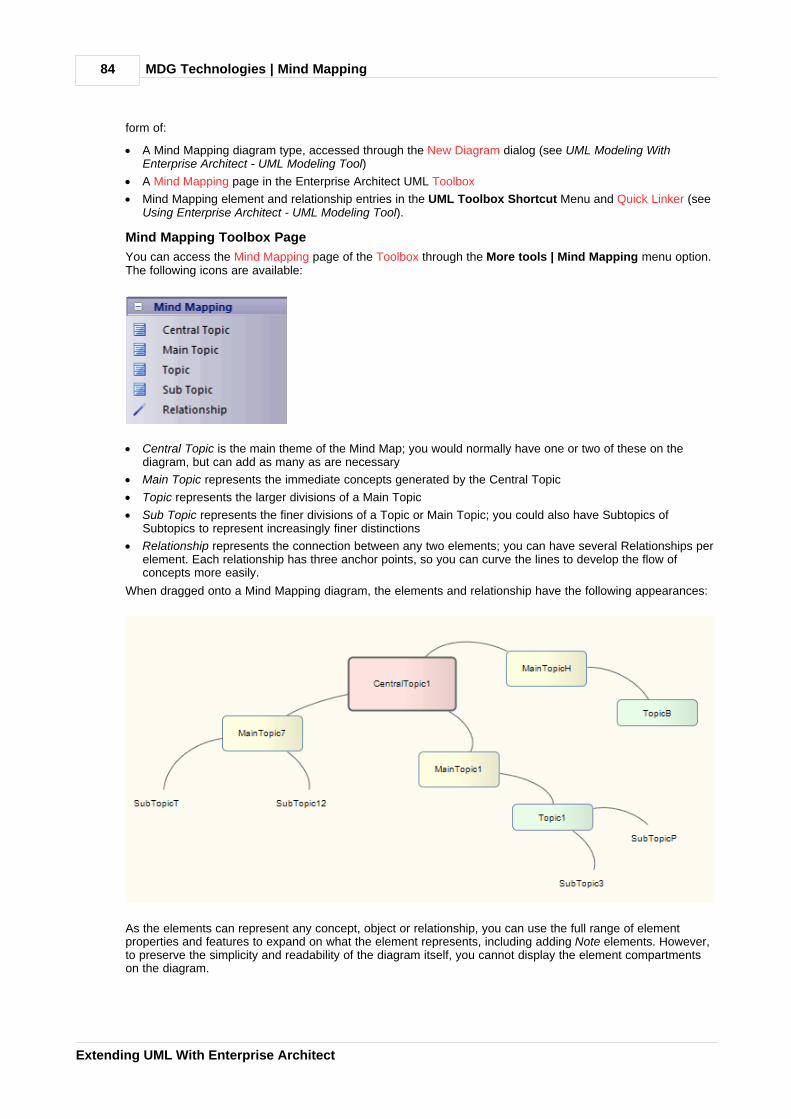
MDG Technologies | Mind Mapping84
Extending UML With Enterprise Architect
form of:
· A Mind Mapping diagram type, accessed through the New Diagram dialog (see UML Modeling WithEnterprise Architect - UML Modeling Tool)
· A Mind Mapping page in the Enterprise Architect UML Toolbox
· Mind Mapping element and relationship entries in the UML Toolbox Shortcut Menu and Quick Linker (seeUsing Enterprise Architect - UML Modeling Tool).
Mind Mapping Toolbox Page
You can access the Mind Mapping page of the Toolbox through the More tools | Mind Mapping menu option.The following icons are available:
· Central Topic is the main theme of the Mind Map; you would normally have one or two of these on thediagram, but can add as many as are necessary
· Main Topic represents the immediate concepts generated by the Central Topic
· Topic represents the larger divisions of a Main Topic
· Sub Topic represents the finer divisions of a Topic or Main Topic; you could also have Subtopics ofSubtopics to represent increasingly finer distinctions
· Relationship represents the connection between any two elements; you can have several Relationships perelement. Each relationship has three anchor points, so you can curve the lines to develop the flow ofconcepts more easily.
When dragged onto a Mind Mapping diagram, the elements and relationship have the following appearances:
As the elements can represent any concept, object or relationship, you can use the full range of elementproperties and features to expand on what the element represents, including adding Note elements. However,to preserve the simplicity and readability of the diagram itself, you cannot display the element compartmentson the diagram.

MDG Technologies | Mind Mapping 85
© 1998-2010 Sparx Systems Pty Ltd
Disable Mind Mapping
If you prefer not to use Mind Mapping in Enterprise Architect, you can disable it (and subsequently re-enableit) using the MDG Technologies dialog (Settings | MDG Technologies).
4.12 SoaML
Note:
Service Oriented Architecture Modeling Language (SoaML) is supported in the Corporate, SystemsEngineering, Business and Software Engineering and Ultimate editions of Enterprise Architect.
The following text is derived from Service oriented architecture Modeling Language (SoaML) - Specification forthe UML Profile and metamodel for Services (UPMS) (OMG document ad/2008-11-01); pp. 25-26:
A service is an offer of value to another through a well-defined interface and available to a community(which may be the general public). A service results in work provided to one by another.
Service Oriented Architecture (SOA) is a way of organizing and understanding [representations of]organizations, communities and systems to maximize agility, scale and interoperability. The SOAapproach is simple - people, organizations and systems provide services to each other. These servicesallow us to get something done without doing it ourselves or even without knowing how to do it -enabling us to be more efficient and agile. Services also enable us to offer our capabilities to others inexchange for some value - thus establishing a community, process or marketplace. The SOA paradigmworks equally well for integrating existing capabilities as for creating and integrating new capabilities.
SOA ... is an architectural paradigm for defining how people, organizations and systems provide anduse services to achieve results. SoaML ... provides a standard way to architect and model SOAsolutions using the Unified Modeling Language (UML). The profile uses the built-in extensionmechanisms of UML to define SOA concepts in terms of existing UML concepts.
... the highest leverage of employing SOA comes from understanding a community, process orenterprise as a set of interrelated services and ... supporting that service oriented enterprise withservice-enabled systems. SoaML enables business oriented and systems oriented servicesarchitectures to mutually and collaboratively support the enterprise mission. ... SoaML depends onModel Driven Architecture® (MDA®) to help map business and systems architectures, the design of theenterprise, to the technologies that support SOA, like web services and CORBA®.
For further information on the concepts of SoaML, see the specification document on the OMG website (http://www.omg.org/docs/ad/08-11-01.pdf).
SoaML in Enterprise Architect
Enterprise Architect enables you to model services architectures quickly and simply, through use of an MDGTechnology integrated with the Enterprise Architect installer. The SoaML facilities are provided in the form of:
· Two SoaML diagram types - SoaML Component Diagram and SoaML Sequence Diagram - accessedthrough the New Diagram dialog (see UML Modeling With Enterprise Architect - UML Modeling Tool)
· SoaML pages in the Enterprise Architect UML Toolbox
· SoaML element and relationship entries in the UML Toolbox Shortcut Menu and Quick Linker (see UsingEnterprise Architect - UML Modeling Tool).
SoaML Toolbox Pages
You can access the SoaML pages of the Toolbox through the More tools | Mind Mapping menu option.There is a set of pages for each SoaML diagram type, although the last six pages in each set are the same.
32
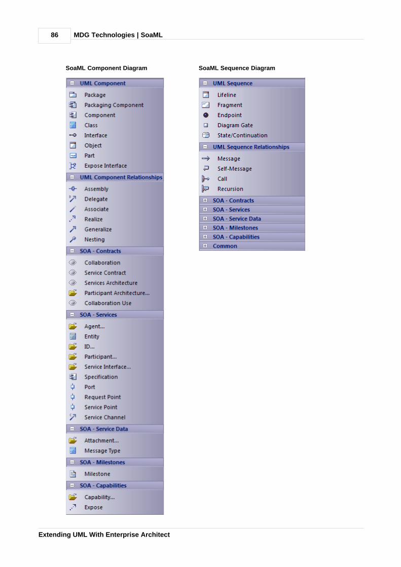
MDG Technologies | SoaML86
Extending UML With Enterprise Architect
SoaML Component Diagram SoaML Sequence Diagram
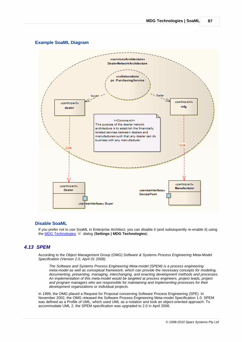
MDG Technologies | SoaML 87
© 1998-2010 Sparx Systems Pty Ltd
Example SoaML Diagram
Disable SoaML
If you prefer not to use SoaML in Enterprise Architect, you can disable it (and subsequently re-enable it) usingthe MDG Technologies dialog (Settings | MDG Technologies).
4.13 SPEM
According to the Object Management Group (OMG) Software & Systems Process Engineering Meta-ModelSpecification (Version 2.0, April 01 2008):
The Software and Systems Process Engineering Meta-model (SPEM) is a process engineeringmeta-model as well as conceptual framework, which can provide the necessary concepts for modeling,documenting, presenting, managing, interchanging, and enacting development methods and processes.An implementation of this meta-model would be targeted at process engineers, project leads, projectand program managers who are responsible for maintaining and implementing processes for theirdevelopment organizations or individual projects.
In 1999, the OMG placed a Request for Proposal concerning Software Process Engineering (SPE). InNovember 2002, the OMG released the Software Process Engineering Meta-model Specification 1.0. SPEMwas defined as a Profile of UML, which used UML as a notation and took an object-oriented approach. Toaccommodate UML 2, the SPEM specification was upgraded to 2.0 in April 2008.
32
MDG Technologies | SPEM88
Extending UML With Enterprise Architect
For more information on the concepts of SPEM, please refer to the full specification at http://www.omg.org/spec/SPEM/2.0/PDF.
SPEM in Enterprise Architect
SPEM 2.0 focuses on providing the additional information structures that you require for processes modeledwith UML 2 Activities or BPMN/BPDM, to describe an actual development process.
Enterprise Architect enables you to develop SPEM diagrams quickly and simply, through use of an MDGTechnology integrated with the Enterprise Architect installer. The SPEM facilities are provided in the form of:
· A SPEM diagram type, accessed through the New Diagram dialog (see UML Modeling With EnterpriseArchitect - UML Modeling Tool)
· A set of SPEM pages in the Enterprise Architect UML Toolbox, providing SPEM elements (stereotypedUML elements)
· SPEM element and relationship entries in the UML Toolbox Shortcut Menu and Quick Linker (see UsingEnterprise Architect - UML Modeling Tool).
Disable SPEM
If you prefer not to use SPEM in Enterprise Architect, you can disable it (and subsequently re-enable it) usingthe MDG Technologies dialog (Settings | MDG Technologies).
89
32

MDG Technologies | SPEM 89
© 1998-2010 Sparx Systems Pty Ltd
4.13.1 SPEM Toolbox Pages
You can access the SPEM pages of the Toolbox through the More tools | SPEM menu option. These pagesprovide the graphical SPEM elements for drawing the diagrams.

MDG Technologies | SPEM90
Extending UML With Enterprise Architect
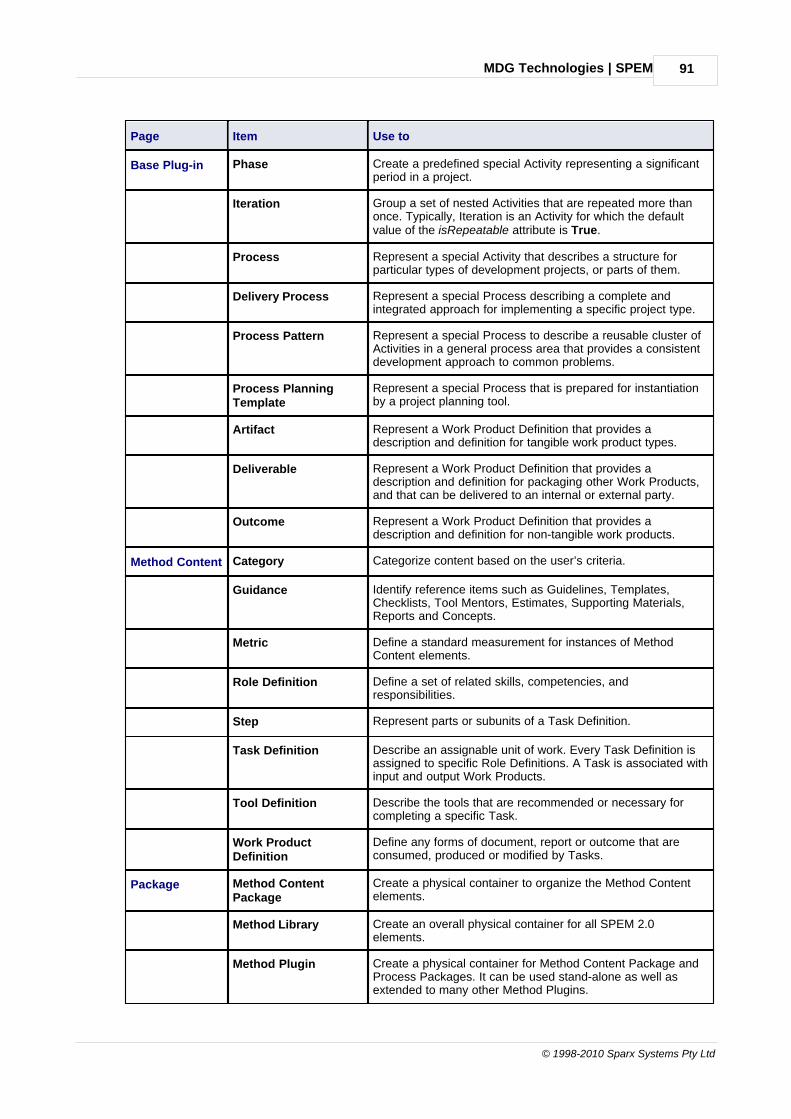
MDG Technologies | SPEM 91
© 1998-2010 Sparx Systems Pty Ltd
Page Item Use to
Base Plug-in Phase Create a predefined special Activity representing a significantperiod in a project.
Iteration Group a set of nested Activities that are repeated more thanonce. Typically, Iteration is an Activity for which the defaultvalue of the isRepeatable attribute is True.
Process Represent a special Activity that describes a structure forparticular types of development projects, or parts of them.
Delivery Process Represent a special Process describing a complete andintegrated approach for implementing a specific project type.
Process Pattern Represent a special Process to describe a reusable cluster ofActivities in a general process area that provides a consistentdevelopment approach to common problems.
Process PlanningTemplate
Represent a special Process that is prepared for instantiationby a project planning tool.
Artifact Represent a Work Product Definition that provides adescription and definition for tangible work product types.
Deliverable Represent a Work Product Definition that provides adescription and definition for packaging other Work Products,and that can be delivered to an internal or external party.
Outcome Represent a Work Product Definition that provides adescription and definition for non-tangible work products.
Method Content Category Categorize content based on the user’s criteria.
Guidance Identify reference items such as Guidelines, Templates,Checklists, Tool Mentors, Estimates, Supporting Materials,Reports and Concepts.
Metric Define a standard measurement for instances of MethodContent elements.
Role Definition Define a set of related skills, competencies, andresponsibilities.
Step Represent parts or subunits of a Task Definition.
Task Definition Describe an assignable unit of work. Every Task Definition isassigned to specific Role Definitions. A Task is associated withinput and output Work Products.
Tool Definition Describe the tools that are recommended or necessary forcompleting a specific Task.
Work ProductDefinition
Define any forms of document, report or outcome that areconsumed, produced or modified by Tasks.
Package Method ContentPackage
Create a physical container to organize the Method Contentelements.
Method Library Create an overall physical container for all SPEM 2.0elements.
Method Plugin Create a physical container for Method Content Package andProcess Packages. It can be used stand-alone as well asextended to many other Method Plugins.

MDG Technologies | SPEM92
Extending UML With Enterprise Architect
Page Item Use to
Process Package Create a physical container that contains different kinds ofProcess element.
Process Component Create a special Process Package that provides themechanism of encapsulation.
Process Activity Define basic units of work within a Process as well as theProcess itself.
Composite Role Represent an aggregation of Role Definition references for anActivity.
Milestone Represent any significant events in a development project.
Process Create a special Activity that describes a structure forparticular types of development project.
Role Use Represent a Role Definition in the context of one specificActivity.
Task Use Represent a Task Definition in the context of one specificActivity.
Team Profile Define a nested hierarchy of teams and team members.
Work Product Use Represent a Work Product Definition in the context of onespecific Activity.
In Enterprise Architect, every SPEM stereotype can be presented in one of two ways:
· Iconic presentation, or
· Textual presentation.
The iconstyle tag is used for switching between these presentations. For example, in the SPEM diagrambelow, if you want the SPEM_TaskDefinition to have iconic presentation you set the iconstyle Tagged Valueto True, and display the element as an icon. To get the textual presentation for SPEM_TaskDefinition, as anoutline with a decoration in the top right corner, set the Tagged Value to False.
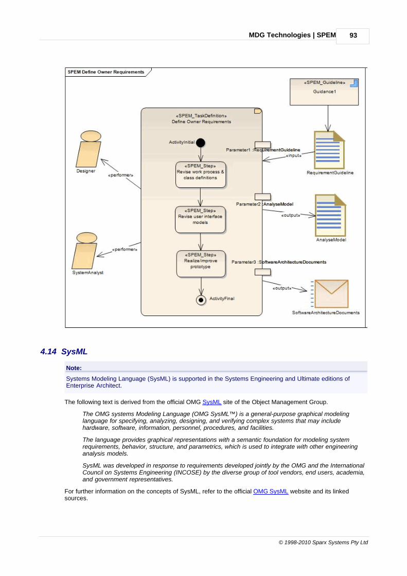
MDG Technologies | SPEM 93
© 1998-2010 Sparx Systems Pty Ltd
4.14 SysML
Note:
Systems Modeling Language (SysML) is supported in the Systems Engineering and Ultimate editions ofEnterprise Architect.
The following text is derived from the official OMG SysML site of the Object Management Group.
The OMG systems Modeling Language (OMG SysML™) is a general-purpose graphical modelinglanguage for specifying, analyzing, designing, and verifying complex systems that may includehardware, software, information, personnel, procedures, and facilities.
The language provides graphical representations with a semantic foundation for modeling systemrequirements, behavior, structure, and parametrics, which is used to integrate with other engineeringanalysis models.
SysML was developed in response to requirements developed jointly by the OMG and the InternationalCouncil on Systems Engineering (INCOSE) by the diverse group of tool vendors, end users, academia,and government representatives.
For further information on the concepts of SysML, refer to the official OMG SysML website and its linkedsources.

MDG Technologies | SysML94
Extending UML With Enterprise Architect
SysML in Enterprise Architect
Enterprise Architect enables you to develop SysML models quickly and simply, through use of an MDGTechnology integrated with the Enterprise Architect installer. The SysML technology provides:
· Each of the nine SysML diagram types, accessed through the New Diagram dialog (see UML ModelingWith Enterprise Architect - UML Modeling Tool)
· A collection of SysML pages in the Enterprise Architect Toolbox that contain each of the supported SysMLelements and relationships
· SysML element and relationship entries in the UML Toolbox Shortcut Menu and Quick Linker (see UsingEnterprise Architect - UML Modeling Tool).
· Simulation of SysML Parametric diagrams, which supports engineering analysis of critical systemparameters including the evaluation of key metrics such as performance, reliability and other physicalcharacteristics.
SysML Toolboxes
You can access the SysML pages of the Toolbox through the More tools | SysML menu option. You can alsoenable SysML as the active technology to access the Toolbox pages directly.
The following sets of Toolbox pages are available:
· Model Elements contains the constructs needed to build SysML models, package structures and views
· Block Definition contains the constructs needed to design SysML blocks, constraint blocks, data andvalue types
· Internal Block contains the constructs needed to design SysML block compositions within Internal BlockDiagrams
· Parametrics contains the constructs needed to construct SysML Parametric Diagrams using constraintblocks
· Activity contains the constructs needed to construct SysML Activity models
· Interaction contains the constructs needed to construct SysML interactions and Sequence diagrams
· State Machine contains the constructs needed to build SysML State Machines
· Use Case contains the constructs needed to build SysML Use Case models
· Requirements contains the constructs needed to build SysML Requirements models.
Disable SysML
If you prefer not to use SysML in Enterprise Architect, you can disable it (and subsequently re-enable it) usingthe MDG Technologies dialog (Settings | MDG Technologies).
4.14.1 SysML Model Elements
You can access the SysML Model Elements Toolbox through the More tools | SysML | SysML ModelElements menu option. These pages provide the SysML elements to build SysML models, package structuresand views.
94
95
97
98
100
102
103
104
105
32

MDG Technologies | SysML 95
© 1998-2010 Sparx Systems Pty Ltd
Page Item Use to
SysML Model Model Create a Package containing a SysML Model.
Package Group model constructs together in a single unit ofcontainment.
View Create a stereotyped Package that defines a SysML View of asystem, from the perspective of a SysML View Point.
View Point Create a stereotyped Class that defines a SysML View Point,which specifies the rules and conventions for the constructionand use of Views.
SysML ModelRelationships
Conform Establish a conformance dependency of a View to the definingView Point.
Containment Graphically display ownership of one element within a parentone.
Dependency Establish a traceable relationship describing how one elementis dependant upon another.
Import Represent a reuse of elements from one model package inanother.
Realization Identify a design fulfillment of a specification betweenelements.
Refine Represent a refinement of one element by another.
4.14.2 SysML Block Definition
You can access the SysML Block Definition Toolbox through the More tools | SysML | SysML BlockDefinition menu option. These pages provide the SysML elements to design SysML blocks, constraint blocks,data and value types.

MDG Technologies | SysML96
Extending UML With Enterprise Architect
Page Item Use to
SysML BlockDefinition
Block Define a composite system entity in SysML.
Actor Represent a user that interacts with one or more SysMLsystems.
Block (constraint) Define a composite constraint as a system of parametricequations.
DataType Define a SysML data type.
ValueType Define a SysML quantity, expressed as a measurabledimension with specific units.
Enumeration Define a data type as a set of symbols or values.
Interface Define an element that describes a specification of aninteraction point with properties and methods.
Signal Define a SysML message, containing attributes, exchangedbetween system blocks in an interaction.
Unit Represent a standard unit of measure in SysML.

MDG Technologies | SysML 97
© 1998-2010 Sparx Systems Pty Ltd
Page Item Use to
Dimension Identify a measurable quantity in SysML.
Part Describe the decomposition of a SysML Block subsystem inthe context of its whole using instances of reusable SysMLBlocks.
Port Describe a structural interaction point of a SysML Block which,in turn, connects between interacting parts of a block.
Port (flow) Describe what flows in and out of interacting SysML Blocks.
Flow Specification Define a set of flow properties that correspond to individualpieces of a common interaction point.
SysML Block Relationships
Item Flow Specify the items that flow across a connector in an interactionpoint.
Dependency Establish a traceable relationship describing how one elementis dependant upon another.
Generalization Describe an element as a specialized descendant of anotherelement, containing additional properties and behavior.
Containment Graphically display ownership of one element within a parentelement.
Association (part) Describe the characteristics of a connection between a SysMLBlock and its internal parts, such as the multiplicity and type.
Association(reference)
Describe the characteristics of a connection between separateSysML Blocks, such as the multiplicity and type.
Association (shared) Describe the characteristics of a common connection betweenSysML Blocks, such as the multiplicity and type.
Allocate Relate model elements together to formalize a refinement ofbehavior, structure, constraints or design expectations.
4.14.3 SysML Internal Block
You can access the SysML Internal Block Toolbox through the More tools | SysML | SysML Internal Blockmenu option. These pages provide the SysML elements to design SysML block compositions within InternalBlock Diagrams.

MDG Technologies | SysML98
Extending UML With Enterprise Architect
Page Item Use to
SysML BlockInternal
Part Describe the decomposition of a SysML Block subsystem inthe context of its whole, using instances of reusable SysMLBlocks.
Connector Part Create a SysML connector part.
Distributed Part Create a SysML distributed part.
Flow Part Create a SysML flow part.
Participant Part Create a SysML participant part.
Signal Define a SysML message, containing attributes, exchangedbetween system blocks in an interaction.
Port Describe a structural interaction point of a SysML Block which,in turn, connects between interacting parts of a block.
Port (flow) Describe what flows in and out of interacting SysML Blocks.
Flow Specification Define a set of flow properties that correspond to individualpieces of a common interaction point.
SysML BlockInternalRelationships
Dependency Establish a traceable relationship describing how one elementis dependant upon another.
Item Flow Specify the items that flow across a connector in an interactionpoint.
Binding Connector Establish a connection between two parts in a systemdecomposition.
4.14.4 SysML Parametrics
You can access the SysML Parametrics Toolbox through the More tools | SysML | SysML Parametricsmenu option. These pages provide the SysML elements to construct SysML Parametric Diagrams usingconstraint blocks.

MDG Technologies | SysML 99
© 1998-2010 Sparx Systems Pty Ltd
Page Item Use to
SysMLParametrics
Constraint Property Instantiate a Constraint Block for use in a Parametric diagram.
Property Define a SysML property typed by a DataType, ValueType orBlock.
SysMLParametricsExtensions
Objective Function Define a SysML Constraint Block for use as an objectivefunction to evaluate Measures of Effectiveness.
Measure ofEffectiveness
Define a SysML property for use as a measure of effectiveness(MOE).
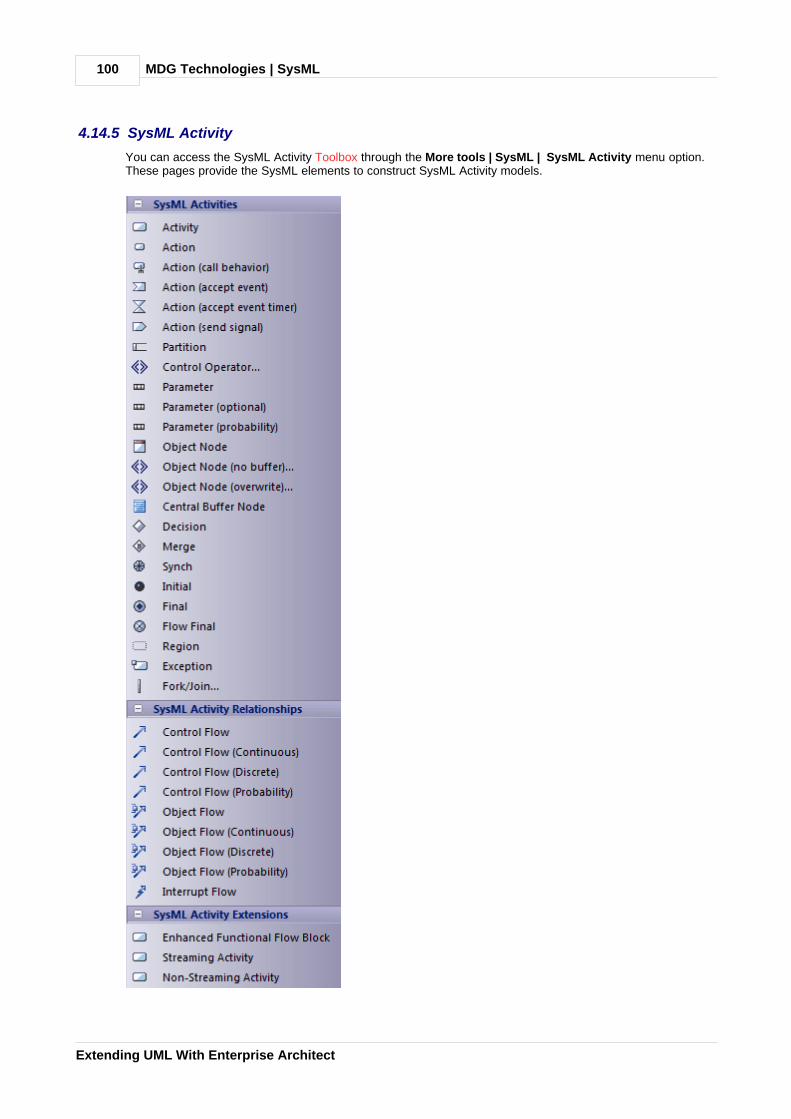
MDG Technologies | SysML100
Extending UML With Enterprise Architect
4.14.5 SysML Activity
You can access the SysML Activity Toolbox through the More tools | SysML | SysML Activity menu option.These pages provide the SysML elements to construct SysML Activity models.
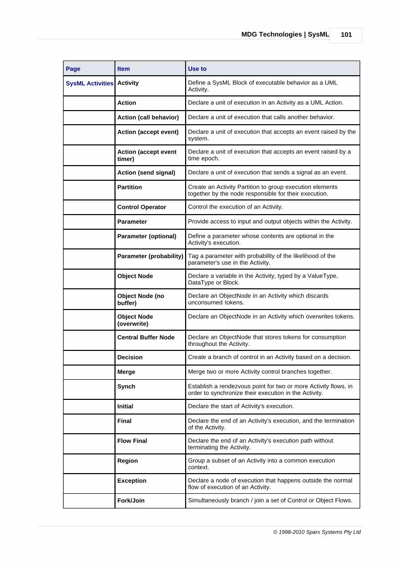
MDG Technologies | SysML 101
© 1998-2010 Sparx Systems Pty Ltd
Page Item Use to
SysML Activities Activity Define a SysML Block of executable behavior as a UMLActivity.
Action Declare a unit of execution in an Activity as a UML Action.
Action (call behavior) Declare a unit of execution that calls another behavior.
Action (accept event) Declare a unit of execution that accepts an event raised by thesystem.
Action (accept eventtimer)
Declare a unit of execution that accepts an event raised by atime epoch.
Action (send signal) Declare a unit of execution that sends a signal as an event.
Partition Create an Activity Partition to group execution elementstogether by the node responsible for their execution.
Control Operator Control the execution of an Activity.
Parameter Provide access to input and output objects within the Activity.
Parameter (optional) Define a parameter whose contents are optional in theActivity's execution.
Parameter (probability) Tag a parameter with probability of the likelihood of theparameter's use in the Activity.
Object Node Declare a variable in the Activity, typed by a ValueType,DataType or Block.
Object Node (nobuffer)
Declare an ObjectNode in an Activity which discardsunconsumed tokens.
Object Node(overwrite)
Declare an ObjectNode in an Activity which overwrites tokens.
Central Buffer Node Declare an ObjectNode that stores tokens for consumptionthroughout the Activity.
Decision Create a branch of control in an Activity based on a decision.
Merge Merge two or more Activity control branches together.
Synch Establish a rendezvous point for two or more Activity flows, inorder to synchronize their execution in the Activity.
Initial Declare the start of Activity's execution.
Final Declare the end of an Activity's execution, and the terminationof the Activity.
Flow Final Declare the end of an Activity's execution path withoutterminating the Activity.
Region Group a subset of an Activity into a common executioncontext.
Exception Declare a node of execution that happens outside the normalflow of execution of an Activity.
Fork/Join Simultaneously branch / join a set of Control or Object Flows.

MDG Technologies | SysML102
Extending UML With Enterprise Architect
Page Item Use to
SysML Activity Relationships
Control Flow Establish a flow of logic between two Activity nodes.
Control Flow(Continuous)
Declare a continuous control flow.
Control Flow(Discrete)
Declare a discrete control flow.
Control Flow(Probability)
Tag a control flow with a probability of the likelihood of theflow's traversal.
Object Flow Establish a flow of objects (data) between two Activity nodes.
Object Flow(Continuous)
Declare a continuous object flow.
Object Flow (Discrete) Declare a discrete object flow.
Object Flow(Probability)
Tag an object flow with a probability of the likelihood of theflow's traversal.
Interrupt Flow Declare a control flow that interrupts flow within a Region.
SysML Activity Extensions
Enhanced FunctionalFlow Block
Declare an Activity used to contain an Enhanced FunctionalFlow Block Diagram (EFFBD).
Streaming Activity Declare an Activity where the flow of tokens passes through itsparameters continuously throughout the Activity's execution.
Non-StreamingActivity
Declare an Activity where the flow of tokens passes through itsparameters at the start of the Activity's execution.
4.14.6 SysML Interaction
You can access the SysML Interaction Toolbox through the More tools | SysML | SysML Interaction menuoption. These pages provide the SysML elements to construct SysML interactions and Sequence diagrams.
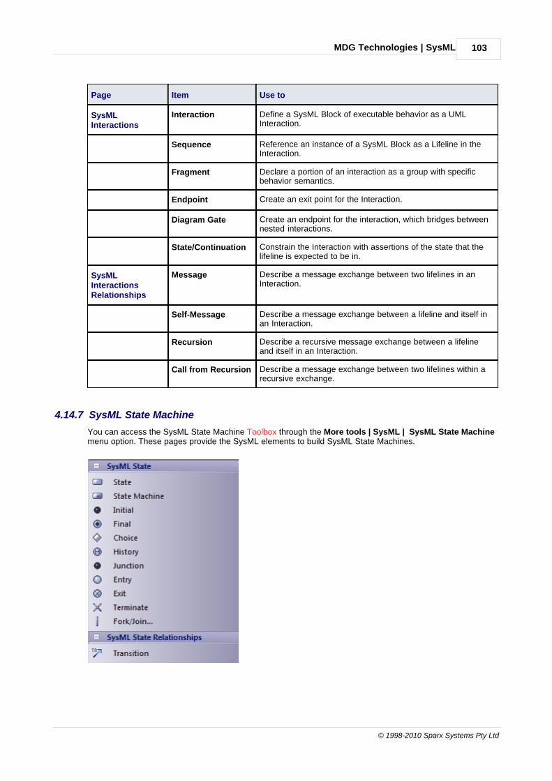
MDG Technologies | SysML 103
© 1998-2010 Sparx Systems Pty Ltd
Page Item Use to
SysMLInteractions
Interaction Define a SysML Block of executable behavior as a UMLInteraction.
Sequence Reference an instance of a SysML Block as a Lifeline in theInteraction.
Fragment Declare a portion of an interaction as a group with specificbehavior semantics.
Endpoint Create an exit point for the Interaction.
Diagram Gate Create an endpoint for the interaction, which bridges betweennested interactions.
State/Continuation Constrain the Interaction with assertions of the state that thelifeline is expected to be in.
SysMLInteractionsRelationships
Message Describe a message exchange between two lifelines in anInteraction.
Self-Message Describe a message exchange between a lifeline and itself inan Interaction.
Recursion Describe a recursive message exchange between a lifelineand itself in an Interaction.
Call from Recursion Describe a message exchange between two lifelines within arecursive exchange.
4.14.7 SysML State Machine
You can access the SysML State Machine Toolbox through the More tools | SysML | SysML State Machinemenu option. These pages provide the SysML elements to build SysML State Machines.
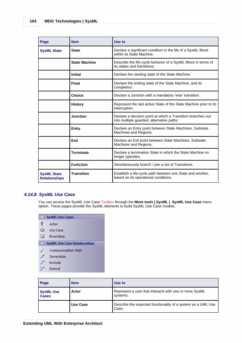
MDG Technologies | SysML104
Extending UML With Enterprise Architect
Page Item Use to
SysML State State Declare a significant condition in the life of a SysML Blockwithin its State Machine.
State Machine Describe the life-cycle behavior of a SysML Block in terms ofits states and transitions.
Initial Declare the starting state of the State Machine.
Final Declare the ending state of the State Machine, and itscompletion.
Choice Declare a Junction with a mandatory 'else' transition.
History Represent the last active State of the State Machine prior to itsinterruption.
Junction Declare a decision point at which a Transition branches outinto multiple guarded, alternative paths.
Entry Declare an Entry point between State Machines, SubstateMachines and Regions.
Exit Declare an Exit point between State Machines, SubstateMachines and Regions.
Terminate Declare a termination State in which the State Machine nolonger operates.
Fork/Join Simultaneously branch / join a set of Transitions.
SysML StateRelationships
Transition Establish a life-cycle path between one State and another,based on its operational conditions.
4.14.8 SysML Use Case
You can access the SysML Use Case Toolbox through the More tools | SysML | SysML Use Case menuoption. These pages provide the SysML elements to build SysML Use Case models.
Page Item Use to
SysML UseCases
Actor Represent a user that interacts with one or more SysMLsystems.
Use Case Describe the expected functionality of a system as a UML UseCase.

MDG Technologies | SysML 105
© 1998-2010 Sparx Systems Pty Ltd
Page Item Use to
Boundary Graphically bound elements in a diagram with a border.
SysML UseCaseRelationships
Communication Path Declare which Actors perform in the Use Case.
Generalize Describe an element as a specialized descendant of anotherelement, containing additional properties and behavior.
Include Describe one Use Case as a subset of another.
Extend Describe one Use Case as an extension of another.
4.14.9 SysML Requirements
You can access the SysML Requirements Toolbox through the More tools | SysML | SysML Requirementsmenu option. These pages provide the SysML elements to build SysML Requirements models.
Page Item Use to
SysMLRequirements
Requirement Specify the capabilities of the system, or the conditions that itshould satisfy.
Test Case Describe the verification of a Requirement through methods ofinspection, analysis, demonstration or testing.
SysMLRequirementRelationships
Containment Graphically display ownership of one element within a parentelement.

MDG Technologies | SysML106
Extending UML With Enterprise Architect
Page Item Use to
Trace Declare a trace relationship between a SysML Requirementand another SysML element.
Copy Declare a copy of one SysML Requirement by another.
Derive Derive a SysML Requirement from another.
Verify Declare a verification of a SysML Requirement by anotherSysML element.
Refine Declare a refinement of a SysML Requirement by anotherSysML element.
Satisfy Declare that the SysML Requirement is satisfied by anotherSysML element.
SysMLRequirementExtensions
Extended Requirement Extend a SysML Requirement with additional Tag properties.
FunctionalRequirement
Declare a SysML Requirement that describes the operation, orbehavior, that the system must perform.
Interface Requirement Declare a SysML Requirement that describes how the systemconnects, or interfaces with, other systems.
PerformanceRequirement
Declare a SysML Requirement that describes how the systemperforms against defined capabilities or conditions.
Physical Requirement Declare a SysML Requirement that describes the physicalcharacteristics, or physical constraints, of the system.
Design Requirement Declare a SysML Requirement that specifies a constraint onthe implementation of the system.

Index 107
© 1998-2010 Sparx Systems Pty Ltd
Index- A -Access
MDG Technologies Remote From EnterpriseArchitect 33
Activate
MDG Technologies 32
Activity (BPEL)
Create 53
Loop 53
Model 53
Sub-Process 53
Task 53
Types 53
Add
Pattern To Diagram 25
Profile Attribute To Diagram 7
Profile Connector To Diagram 7
Profile Element To Diagram 7
Profile Operation To Diagram 7
UML Pattern To Diagram 25
Alternative Image
Stereotype 20
Apply
Stereotype To Element 16
Stereotype To UML Construct 16
Archimate
Concept 34
Diagram 34
Disable 34
Elements 34
Enable 34
MDG Technology 34
Relationships 34
Toolbox Pages 34
Assignments
BPEL, Create 61
Attribute
Supported, By XML Element Node 12
Supported, In UML Profile 12
- B -BPEL
Assignments, Create 61
BPMN Elements Not Mapable 40
Concepts 37
Create Assignments 61
Create Model 38
Diagram 37
Disable 37
End Event, Model 44
Generate 63
In Enterprise Architect 37
Intermediate Event, Model 47
Looping Constructs 53
MDG Technology 37
Model A Process 40
Model Activity 53
Model Gateway 51
Model Pool 58
Model Sequence Flow Connector 59
Model Validation 65
Model, Create 38
Modeling Restrictions 37
Package Structure 38
Process, Properties 40
Start Event, Model 41
Sub Process Types 53
Task Types 53
Validation Violations 65
Web Service, Create 64
BPMN
1.0 67
1.1 67
Change Element Appearance 70
Concepts 67
Connectors 67
Core Toolbox Page 67
Diagram 67
Disable 67
Element Appearance, Change 70
Elements 67
MDG Technology 67
Migrate 1.0 Model To 1.1 71
Relationships 67
Types Toolbox Page 67
Update Version Via Toolbox Element 70
Version Differences In Appearance 70
BPMN 1.1
Activity Types 53
BPEL Sequence Flow 59
Elements Not Mappable to BPEL 40
End Event, Types 44
Gateway Types 51
Intermediate Event, Types 47
Pool 58
Start Event, Types 41
Sub-Process Types 53
Index108
Extending UML With Enterprise Architect
BPMN 1.1
Task Types 53
Business Process Execution Language (BPEL) 37
Business Process Modeling Notation (BPMN) 67
- C -Change
BPMN Element Appearance 70
Concept
Archimate 34
BPEL 37
BPMN 67
Eriksson-Penker MDG Technology 76
Mind Mapping 83
SoaML 85
SPEM 87
SysML 93
Connector
BPMN 67
Data Flow 72
Entity Relationship Diagram 74
SysML Activity 100
SysML Block Definition 95
SysML Interaction 102
SysML Internal Block 97
SysML Model 94
SysML Parametric 98
SysML Requirement 105
SysML State Machine 103
SysML Use Case 104
Constraint
Synchronize, And Tagged Values 8
Synchronize, From MDG Toolbox Pages 8
Synchronize, From Resources Window 8
Context Diagram 72
Context Menu
Apply «Stereotype» Option 8
Create
Activity, BPEL 53
BPEL Assignments 61
BPEL Model 38
BPEL Web Service 64
End Event, BPEL 44
Gateway, BPEL 51
Intermediate Event, BPEL 47
Pattern 22
Pool, BPEL 58
Sequence Flow, BPEL 59
Start Event, BPEL 41
UML Pattern 22
- D -Data Flow
Concepts 72
Connector 72
Context Diagram 72
Diagram 72
MDG Technology 72
Relationship 72
Toolbox Page 72
Data Store
Element (Data Flow Diagram) 72
Design
Patterns 22
Diagram
Add Profile Feature 7
Add Profile Object 7
Archimate 34
BPEL 37
BPMN 67
Context 72
Data Flow 72
Entity Relationship 74
Eriksson-Penker 76
Mind Mapping 83
Save As Pattern 22
SoaML 85
SPEM 89
SysML 93
Disable
Archimate 34
BPEL 37
BPMN 67
Data Flow Diagrams 72
Entity Relationship Diagram 74
Eriksson-Penker MDG Technology 76
Gang Of Four Pattern Technology 79
GoF Pattern Technology 79
ICONIX 80
MDG Technologies 32
Mind Mapping 83
SoaML 85
SPEM 87
SysML 93
Download
Gang Of Four Patterns 25
GoF Patterns 25

Index 109
© 1998-2010 Sparx Systems Pty Ltd
- E -Edit
Pattern Default 25
Element
Archimate 34
BPMN 67
BPMN, Change Appearance 70
Change Appearance, BPMN 70
Data Store, Data Flow Diagram 72
Entity, Entity Relationship Diagram 74
Eriksson-Penker 76
External, Data Flow Diagram 72
Gang Of Four Pattern 79
GoF Pattern 79
Mind Mapping 83
N-Ary, Entity Relationship Diagram 74
Process, Data Flow Diagram 72
Relationship, Entity Relationship Diagram 74
SoaML 85
SPEM 89
Synchronize Stereotypes With Profile 8
SysML Activity 100
SysML Block Definition 95
SysML Interaction 102
SysML Internal Block 97
SysML Model 94
SysML Parametric 98
SysML Requirement 105
SysML State Machine 103
SysML Use Case 104
Templates And Profiles 4
Enable
Archimate 34
Data Flow Diagrams 72
Entity Relationship Diagram 74
Eriksson-Penker MDG Technology 76
Gang Of Four Pattern Technology 79
GoF Pattern Technology 79
ICONIX 80
MDG Technologies 32
Mind Mapping 83
SoaML 85
SPEM 87
End Event, BPEL
Create 44
Model 44
Types 44
Enterprise Architect UML Toolbox
MDG Technology Groups 30
Entity
Element (Entity Relationship Diagram) 74
Entity Relationship Diagram
Concepts 74
Connector 74
Elements 74
Example Diagram 74
MDG Technology 74
Relationship 74
Tagged Values 74
Toolbox Page 74
ERDs 74
Eriksson-Penker
Concept 76
Diagram 76
Disable 76
Elements 76
Enable 76
Extensions 76
MDG Technology 76
Relationships 76
Toolbox Page 76
Example Diagram
Entity Relationship Diagram 74
Exclusive Gateway
Data-Based 51
Event-Based 51
Extending UML
And MDG Technologies 2
With Enterprise Architect 2
With UML Patterns In Enterprise Architect 2
With UML Profiles In Enterprise Architect 2
With UML Stereotypes In Enterprise Architect 2
Extension
SysML Requirement 105
External
Element (Data Flow Diagram) 72
- G -Gang Of Four Pattern
Concepts 79
Download 22, 25
MDG Technology 79
Toolbox Page 79
Gateway
Create 51
Exclusive (XOR) 51
Inclusive (OR) 51
Model In BPEL 51
Parallel (AND) 51

Index110
Extending UML With Enterprise Architect
Gateway
Types 51
Generate
BPEL 63
GoF Pattern
Concepts 79
Download 22, 25
MDG Technology 79
Toolbox Page 79
Guillemets 19
- I -ICONIX
Disable 80
Elements 80
Enable 80
Layout 80
MDG Technology 80
Relationships 80
Roadmap 80
UML Toolbox Pages 80
Import
MDG Technologies 28
Pattern 25
UML Pattern 25
UML Profiles 6
Intermediate Event, BPEL
Create 47
Model 47
Types 47
- L -Layout
ICONIX 80
- M -Manage
MDG Technologies 32
MDG Technology
Access, Remote From Enterprise Architect 33
Activate 32
And Resources Window 30
Disable 32
Enable 32
Import 28
Introduction 28
Link for Downloads 28
Manage 32
Toolbox Groups 30
MDG Technology (Integrated)
Archimate 34
BPEL 37
BPMN 67
Data Flow Diagram 72
Entity Relationship Diagram 74
Eriksson-Penker 76
Gang Of Four Pattern 79
GoF Pattern 79
ICONIX 80
Mind Mapping 83
SoaML 85
SPEM 87
SysML 93
Migrate
BPMN 1.0 Model To 1.1 71
MigrateToBPMN11()
Function 71
Mind Mapping
Concept 83
Diagram 83
Disable 83
Elements 83
Enable 83
MDG Technology 83
Relationship 83
Toolbox Page 83
Model
Activity, BPEL 53
BPEL Process 40
BPEL, Create 38
Gateway, BPEL 51
Pool, BPEL 58
Sequence Flow, BPEL 59
Model Validation
BPEL Violations 65
Of BPEL 65
- N -N-Ary
Element (Entity Relationship Diagram) 74
- P -Package Structure
BPEL 38
Pattern
Action, Modify 25
Actions 22

Index 111
© 1998-2010 Sparx Systems Pty Ltd
Pattern
Create From Diagram 22
Default, Change 25
Design 22
Gang of Four 22
GoF 22
GoF, Download 25
Import Into Model 25
In Resources View 22
Save 22
Save From Diagram 22
Pool (BPEL)
Create 58
Model 58
Process
BPEL, Properties 40
Element (Data Flow Diagram) 72
Profile
Add Attribute To Diagram 7
Add Connector To Diagram 7
Add Element To Diagram 7
Add Operation To Diagram 7
And Element Templates 4
Example File 13
Import 6
Import From XML 4
References 10
Stereotypes 4
Use 5
Profile Connector
Add To Diagram 7
Profile Element
Add To Diagram 7
- R -Relationship
Archimate 34
BPMN 67
Data Flow 72
Element (Entity Relationship Diagram) 74
Entity Relationship Diagram 74
Eriksson-Penker 76
Mind Mapping 83
SysML Activity 100
SysML Block Definition 95
SysML Interaction 102
SysML Internal Block 97
SysML Model 94
SysML Parametric 98
SysML Requirement 105
SysML State Machine 103
SysML Use Case 104
Resources
Window, And MDG Technologies 30
Resources View
Of Patterns 22
Result
End Event, BPEL 44
Roadmap
ICONIX 80
- S -Save
Diagram As UML Pattern 22
UML Pattern 22
Select
Stereotypes 17
Sequence Flow
Create 59
Model In BPEL 59
Service Oriented Architecture Modeling Language 85
Set
Element Classifier 25
Show
Element Stereotype 18
Feature Stereotype 18
SOA
Modeling Language 85
SoaML
Concept 85
Diagrams 85
Disable 85
Elements 85
Enable 85
MDG Technology 85
Toolbox Pages 85
Software and Systems Process EngineeringMeta-model
SPEM 87
SPEM
Base Plug-In 87
Concept 87
Diagram 89
Disable 87
Elements 89
Enable 87
MDG Technology 87
Method Content 87
Package 87
Process 87

Index112
Extending UML With Enterprise Architect
SPEM
Software and Systems Process EngineeringMeta-model 87
Stereotype Presentation 89
Toolbox Page 89
Standard Element Stereotypes 19
Start Event, BPEL
Create 41
Model 41
Types 41
Stereotype
And Metafiles 15
Definition 15
Selector 17
SPEM Presentation 89
Standard Element 19
Synchronize Element With Profile 8
UML Description 15
Visibility 18
With Alternative Images 20
Supported Attribute
By XML Element Node 12
In UML Profiles 12
Supported Tags
In UML Profiles 10
Synchronize
By Dragging Element From Toolbox 8
Elements With Profile 8
Stereotypes From Profile 8
Tagged Values And Constraints 8
Tagged Values From MDG Toolbox Pages 8
Tagged Values From Resources Window 8
UML Profile Tagged Values And Constraints 8
SysML
Activity Elements, Toolbox Page 100
Activity Relationships, Toolbox Page 100
Block Definition Elements, Toolbox Page 95
Block Relationships, Toolbox Page 95
Concepts 93
Diagrams 93
Disable 93
Interaction Elements, Toolbox Page 102
Interaction Relationships, Toolbox Page 102
Internal Block Elements, Toolbox Page 97
Internal Block Relationships, Toolbox Page 97
MDG Technology 93
Model Elements, Toolbox Page 94
Model Relationships, Toolbox Page 94
Parametric Elements, Toolbox Page 98
Parametric Relationships, Toolbox Page 98
Requirement Elements, Toolbox Page 105
Requirement Extensions, Toolbox Page 105
Requirement Relationships, Toolbox Page 105
State Machine Elements, Toolbox Page 103
State Machine Relationships, Toolbox Page 103
Toolbox Pages 93
Use Case Elements, Toolbox Page 104
Use Case Relationships, Toolbox Page 104
Systems Modelling Language (SysML) 93
- T -Tagged Value
By Dragging Element From Toolbox 8
Entity Relationship Diagram 74
In UML Profiles 8
Supported For UML Profile Stereotypes 10
Synchronize, And Constraints 8
Synchronize, From MDG Toolbox Pages 8
Synchronize, From Resources Window 8
Template
Element 4
Trigger
Intermediate Event, BPEL 47
Start Event, BPEL 41
- U -UML
Extending 2
Pattern 22
UML Pattern
Actions 22
Add To Diagram 25
Create From Diagram 22
In Resources View 22
Save 22
Save From Diagram 22
UML Profile
And Element Templates 4
Example File 13
Import 6
Import From XML 4
Stereotypes 4
Structure 11
Synchronize Elements 8
Synchronize Stereotypes 8
Synchronize Tagged Values And Constraints 8
UML Resources
Patterns 22, 25
UML Toolbox
Archimate Group 34
Index 113
© 1998-2010 Sparx Systems Pty Ltd
UML Toolbox
BPMN Group 67
Data Flow Diagram Group 72
Entity Relationship Diagram 74
Eriksson-Penker Group 76
Gang Of Four Pattern Group 79
GoF Pattern Group 79
ICONIX Group 80
MDG Technology Groups 30
Mind Mapping Group 83
SoaML Pages 85
SPEM 89
SysML Groups 93
Use
Pattern 25
Profiles 5
- W -Web Service
Create In BPEL 64
Web Services Business Process ExecutionLanguage (WS-BPEL) 37
What Is
A Pattern? 22
Working
With MDG Technologies 30
WS-BPEL 37
- X -XML
Pattern File 22

Extending UML With Enterprise Architect
www.sparxsystems.com


![Extending UML for Modeling Data Mining Projects (DM-UML) · Extending UML for Modeling Data Mining Projects (DM-UML) ... rules for social networking data. Rizzi [32] also defines](https://img.dokumen.tips/doc/110x75/5e8c070097d20636b84df1c5/extending-uml-for-modeling-data-mining-projects-dm-uml-extending-uml-for-modeling.jpg)