Embed Size (px)
Citation preview

S-SPA
SHEET NO.
ACAD FILE NAME
SPECIF_A.DWG
OUTLINE SPECIFICATIONS FOR CONSTRUCTION OF WATER DISTRIBUTION SYSTEM
GENERAL NOTES
FINAL INSPECTION PROCEDURES
OUTLINE SPECIFICATIONS FOR CONSTRUCTION OF SEWAGE COLLECTION SYSTEM
1. The installation of all pipe, regardless of the type or size, shall be installed in
accordance with
the Manufacturer's specifications or recommended criteria for the pipe being installed. No
pipe shall be installed with the joints over-assembled or over-homed. The reference mark
(home-line) shall not be installed into the bell beyond the Manufacturer's recommendation.
The Contractor shall be responsible to mark any pipe cut to length with a reference mark
(home-line) placed at the correct location on the pipe according to the type and size pipe
being installed. CCUA will not permit any pipe joint to be left in place if the joint is
over-homed. It shall be the Contractor's responsibility to obtain the information pertaining
to installation of pipe to be installed from the Supplying Manufacturer and to install the pipe
accordingly.
2. Deflection of all pipe, regardless of the type or size, shall be installed in accordance
with the Manufacturer's specifications or recommended criteria for the pipe being installed.
Any pipe which has been installed and does not meet the above listed criteria shall be
removed and replaced with new pipe. All costs of removal and reinstallation of said pipe
shall be at the Contractor's expense, with no cost to the Owner, and shall meet all CCUA
requirements.
3. Any utility pipe, regardless of the type or size, which has been abandoned, or taken out
of service or out of use for any reason, shall either be removed from the ground for its
entire length and disposed of in a legal manner, or shall be grout filled in place for its entire
length. A CCUA inspector shall be present and witness the grout filling of the pipe from
start to finish of the process. If the abandoned pipe is being removed, a CCUA inspector
shall be present or be able to view the open ditch where pipe was removed from prior to
backfilling that ditch.
4. Disinfection Notes:
a. Only CCUA staff is authorized to change or adjust existing CCUA valves.
b. The General Superintendent of the Distribution and Collection System must be informed
of any changes to existing CCUA valves.
c. The scheduling of the disinfection process for new developments installing water mains
must be coordinated with CCUA at least seven (7) days in advance.
d. CCUA inspectors must be present to observe and monitor the disinfection process.
SPECIAL NOTES
ST
AN
DA
RD
W
AT
ER
A
ND
S
EW
ER
S
YS
TE
M O
UT
LIN
E
TE
CH
NIC
AL S
PE
CIF
IC
AT
IO
NS
F
OR
C
LA
Y C
OU
NT
Y
UT
ILIT
Y A
UT
HO
RIT
Y IN
IT
IA
TE
D P
RO
JE
CT
S
(F
OR
C
CU
A IN
IT
IA
TE
D P
RO
JE
CT
S O
NLY
)
01. INTENTION. It is the declared and acknowledged intention to secure a new sewerage system, complete, in
accordance with the plans, specifications, and contract documents. All new work shall be in accordance with Clay
County Utility Authority Specifications and Details and with the Clay County Utility Authority Approved Materials
Manual.
02. GENERAL. All materials shall be of those listed in the CCUA Approved Materials Manual. The installation
shall be warranted by the Contractor as to materials, workmanship and accuracy of the asbuilt drawings for a
period of two years from the date of completion of the work or beneficial use of the facilities. Workmanship shall
be of good quality; i.e., sewers shall be laid true to line and grade, fittings shall be properly installed and
restrained, trenches shall be properly excavated and backfilled, manholes shall be installed at locations and to
elevations shown on the plans.
02.1 Contractor LICENSE AND APPROVAL. Utility reserves the right to approve or deny approval of Contractor
prior to construction of any on-site or off-site utility facilities. Contractor must hold a State Of Florida Underground
Utility Contractors license, that named contracting company being the one doing the work on project, and
demonstrate acceptable experience in the field of utility construction.
03. SURVEYS. The Utility Contractor shall provide all surveys necessary for the layout and construction of the
work of his contract.
04. EARTHWORK. Earthwork shall include all excavation, fill and backfill (hand/machine), compaction and
rough grading of materials encountered. No unsuitable materials clay, muck, or peat removed from pipe trenches
are to be used for backfill. All fill or backfill shall be either sand or sandy clay, free of roots, trash or other debris.
All backfill alongside of and to a height twenty-four inches above all pipe shall be free of clay or organic material,
compacted by either hand or machine operation carefully to 98%. All other backfill shall be compacted by either
hand or machine operation carefully to 95% (outside of paving), 98% (under paving) of its optimum moisture
content as determined by ASTM D698, latest.
05. MANHOLES. Manhole bases, sections, and cones shall conform to the requirements of ASTM C478,
Specifications for Precast Reinforced Concrete Manhole Sections. Cement shall meet the requirements of ASTM
C150, Specifications for Portland Cement, Type II. Concrete shall meet the minimum requirements for Class "A"
Concrete Work. Minimum wall thickness shall be 1/12 the inside diameter in inches plus one (1) inch. Bases for
manholes shall be cast integrally with the bottom manhole section. Joint contact surfaces shall be formed with
machined castings; they shall be exactly parallel with a 2 degree slope and nominal 1/16 inch clearance with the
tongue equipped with a proper recess for the installation of an O-ring rubber gasket, conforming to ASTM C443,
Joints for circular Concrete sewer and Culvert pipe using Rubber gasket, or RAM-NEK premolded Plastic Joint
Sealer with joints. Manhole adjustment materials shall be sound, hard, and pre-primed. Precast concrete
adjustment rings as manufactured by Taylor Precast Co. (or equal) may be utilized in lieu of brick adjustment.
Mortar shall be one part cement Type II and two parts sand; lime shall not be used. The outside faces of brick
masonry shall be plastered with mortar 1/4" to 3/8" thick. Precast manhole walls shall not be coated unless
otherwise noted. Cement grout for manhole bottoms shall be a stiff rich mix of Type II Portland Cement and sharp
plaster sand. Calcium chloride may be added (maximum of 2%) to aid in obtaining a faster set. At permanent
pump station locations, the first upstream manhole from the station shall be lined with a polyethylene liner as
manufactured and installed by Taylor Precast Co., or approved equal.
05.1 CAST IRON MANHOLE FRAMES AND COVERS. Cast iron manhole frames and covers shall be as
detailed on drawings. Castings shall meet the requirements of ASTM A48, Specifications for Gray Iron Castings,
Class No. 30, or Grade 65-45-12, Ductile Iron meeting the requirements of ASTM A536, Standard Specification
for Ductile Iron Castings. In either case, manhole frame and cover shall be designed to withstand an hs20-44
loading defined in the AASHTO specifications. Frames and covers shall be machined or ground at touching
surfaces so as to seat firmly and prevent rocking.
05.2 FLEXIBLE MANHOLE CONNECTOR. All connections between sewer pipe and pre-cast concrete
manholes shall be accomplished by a Flexible Connector, "Kor-N-Seal", as manufactured by National Pollution
Control Systems, Inc., or approved equal.
05.3 FLOW CHANNELS. Flow channels in manhole base shall be formed of D.O.T. Class I Type II cement grout
with brick and trowel to a smooth surface finish. Grout surface shall be 1" min. thickness over brick. While the
manholes are under construction, cut off pipes at inside face of the manhole and construct the invert to the shape
and sizes of pipe indicated. All inverts shall provide a constant gradient from influent pipe to effluent pipe through
manhole. Changes in direction of the sewer and entering branch or branches shall be laid out in smooth curves of
the longest possible radius which is tangent to the center lines of adjoining pipelines.
05.4 DROP INLETS. Where shown on the drawings, drop inlets to the manholes shall be constructed as shown
on the drawings and specified herein.
06. POLYVINYL CHLORIDE PIPE. Polyvinyl Chloride Sewer Pipe shall conform to the requirements of ASTM
D-3034, SDR 26. The PVC compound conforming to ASTM D-1784. Pipe shall be clearly marked in 5 ft. intervals
or less, indicating manufacturers name, nominal size, cell classification and legend. Joints shall be push-on
rubber gasketed, conforming to ASTM D-3034. Pipe and fittings shall be installed in accordance with
recommended practice ASTM D-2321. Sewers over 13' in depth shall be DR-18 P.V.C. pipe, including all fittings
and service laterals, and shall have CCUA approval prior to design or installation of said sewer.
07. PIPE BETWEEN MANHOLES. All piping installed between manholes shall be the same material and class.
No dissimilar pipe material will be allowed anywhere within a single run of pipe.
08. SANITARY SERVICE LATERALS. Sanitary service laterals shall be Polyvinyl Chloride Pipe conforming to
the requirements of ASTM D-3034, SDR 26 where cover over top of pipe is 36 inches or greater. Where cover
over top of pipe is less than 36 inches, specific construction conditions shall be directed by the Clay County Utility
Authority. All sanitary service laterals shall be a minimum of 4'-0" deep at the right-of-way line to top of pipe. Any
sanitary service lateral which must be more than 6'-0" deep shall not be installed prior to obtaining permission
from the CCUA field inspector or CCUA Engineering Department. All sanitary service laterals shall be 6-inch
diameter from the main to the right-of-way line with a minimum slope of 0.60% (0.6 feet per hundred feet). In
single family residential developments, services shall reduce to 4" in size at the property line utilizing the proper
fittings for the type of pipe specified. All sewer service laterals over 13' deep shall be constructed of DR-18 PVC
pipe, and DR-18 pipe fittings, per CCUA standard sewer system details.
09. FORCE MAINS. Force mains shall be C900 DR-18 PVC and conform to the requirements of ASTM D-1784,
D-2241, D-3139 and F-477. Pipe shall be color coded and marked "FORCE MAIN" on at least two sides and at
every 12" along the barrel of the pipe. Ductile iron pipe for force main service shall be polylined. Ductile iron pipe
is not to be used without prior approval of the Clay County Utility Authority. Fittings shall be C110 gray iron and
shall be polylined. Force mains less than 3" shall be Sch. 80 PVC. All force mains shall be installed with tracer
wire per CCUA standard location wire details. Forcemains run with reclaimed mains shall be 5' deep.
09.1 LIFT STATION VALVES. See CCUA Approved Materials Manual for acceptable plug valves and check
valves.
09.2 FORCE MAIN VALVE. Gate valve, resilient seated, same as specified in Water Distribution System
Specifications Section 11 at right. Valve box shall have the word "SEWER" cast into the cover.
09.3 FORCE MAIN JOINT RESTRAINT. All fittings shall be properly and adequately restrained against lateral
movement at all force main tees, crosses, valves and bends. See CCUA Approved Materials Manual for
acceptable restraints (SEE RESTRAINED JOINT SCHEDULE).
09.4 FORCE MAIN PIPE FLUSHING. All force main piping shall be flushed clean with water
utilizing full pipe diameter flushing for all piping up to and including 8" diameter.
10. INSTALLATION. All sewer lines, manholes, and appurtenances shall be constructed to the dimensions and
elevations indicated on the drawings. Trenches shall be excavated to a width approximately twelve inches greater
than the outside diameter of the pipe. Machine excavation shall be to a depth one-fourth pipe diameter above
proposed pipe grade; the remaining depth shall be hand excavated and shaped to give full support to the lower
one-fourth of each pipe.
Each section of pipe shall be inspected for defects prior to being lowered into the trench. The inside of each bell
and the outside of each spigot shall be thoroughly cleaned of all foreign matter prior to making the joint. All sewer
lines shall be constructed with the spigot ends pointing in the direction of the flow. Both the bell and the spigot of
each joint shall be lubricated with the lubricant recommended by the pipe manufacturer. All sewer lines shall be
cleaned of foreign matter as construction progresses, and shall be in a clean condition upon completion of
construction operations. Pipe materials shall remain the same on runs between manholes and / or other
structures.
11. INSPECTIONS. Each section of the completed sewer system shall be inspected for proper alignment.
Inspection shall consist of "lamping" from manhole to manhole. Any section of the sewer system which does not
display true, concentric alignment shall be reinstalled at no additional expense to the Owner. A written log of
inspection shall be kept indicating location of test, potential problems in sewer, dips and depth of water, service
locations, and other irregularities in the pipe lines. An image in DVD format shall be made of the television
inspection and submitted to the Engineer and the Clay County Utility Authority.
11.1 TELEVISION INSPECTION. Television inspection will be required on all new gravity sewers constructed.
This service shall be provided by the Contractor as a part of this Contract. The newly constructed sewers shall be
televised in the presence of the Inspector of the Clay County Utility Authority. A full report as to the condition of
pipe, type, depth, location of services, length, joint and distance between manholes, etc. shall be furnished to the
CCUA inspector prior to the final acceptance of the system. Any pipe found to be cracked, leaking or otherwise
defective shall be removed and replaced with new pipe at no additional costs to the Owner. Deflection testing with
5% mandrel also required. Any section not passing the mandrel test shall be corrected. Sewer mains shall be
televised after curb and lime rock are in place but prior to paving. Curb and limerock shall be installed, finish
graded prior to televising the gravity sewer. Limerock priming and paving operations shall not take place until the
CCUA inspector has reviewed the television recorded DVD and approves the gravity sewer system. This will be
strictly enforced. All gravity sewers must be flushed no sooner than 4 hours prior to any television inspection.
Force main lines shall be pressure tested and approved prior to paving, but not prior to subgrade mixing operation
and limerock installation, finish graded and compacted. Sewer services shall be viewed by a camera capable of
viewing into service lateral connections. Adequate water must be placed within the upstream manhole to flow
through the downstream manhole before inspecting with the camera. All work must be accomplished in the
presence of the CCUA inspector and a 48 hour notice must be provided. Contractor shall provide CCUA with a 48
hr. notice of intent to televise and inspect sewer main. CCUA inspector shall report to job site at the time specified
by Contractor at the time of the call-in. CCUA inspectors will wait at the job site no more than one hour for the
televising to begin before leaving the job site. Contractor shall reschedule televising giving CCUA 48 hrs. notice if
the above occurs.
11.2 INFILTRATION TEST After completion, the sewers or sections thereof, shall be tested and gauged for
infiltration. To check the amount of infiltration, the Contractor, at no added compensation over the contract price
for the sewers, shall furnish, install, and maintain a V-notch sharp crested weir in a wood frame on the main
sewers as directed by the Engineer. Maximum allowable infiltration shall be 50 gallons per mile, per inch of dia. of
sewer per 24 hour day at any time.
11.3 EXFILTRATION TEST In areas where ground water is not encountered in sewer construction, or it is
desired to run exfiltration tests, the Contractor shall furnish and install all necessary materials, equipments, shall
supply water, etc., and shall run exfiltration tests to determine acceptance of the sewer. The maximum allowable
exfiltration shall be 50 gallons per mile per inch of diameter of sewer per 24 hour day at any time based on two
foot minimum internal head of 4'-0" deep at the right-of-way line to top of pipe.
01. INTENTION. It is the declared and acknowledged intention to secure a new water distribution system,
complete, in accordance with the plans and specifications, and contract documents. All new work shall be in
accordance with Clay County Utility Authority Specifications and Details and Approved Materials Manual.
02. GENERAL. All materials shall be of those listed in the CCUA Approved Materials Manual. Materials shall be
warranted by the Contractor as to materials, workmanship and accuracy of asbuilt drawings for a period of two
years from the date of completion of the work or beneficial use of the facilities. Workmanship shall be of good
quality; i.e., mains shall be laid in a uniform alignment, fittings shall be properly restrained, trenches shall be
properly excavated and backfilled, fire hydrants and valve boxes shall be adjusted to finished grade. All water
mains shall be installed with tracer wire per CCUA standard location wire details.
02.1 Contractor LICENSE AND APPROVAL. Utility reserves the right to approve or deny approval of Contractor
prior to construction of any on-site or off-site utility facilities. Contractor must hold a State Of Florida Underground
Utility Contractors license, that named contracting company being the one doing the work on project, and
demonstrate acceptable experience in the field of utility construction.
03. SURVEYS. The Utility Contractor shall provide all surveys necessary for the layout and construction of the
work of his contract.
04. EARTHWORK. Earthwork shall include all excavation, fill and backfill (hand/machine), compaction and
rough grading of materials encountered. No unsuitable materials clay, muck, or peat removed from pipe trenches
are to be used for backfill. All fill or backfill shall be either sand or sandy clay, free of roots, trash or other debris.
All backfill alongside of and to a height twenty-four inches above all pipe shall be free of clay or organic material,
compacted by either hand or machine operation carefully to 98%. All other backfill shall be compacted by either
hand or machine operation carefully to 95% (outside of paving), 98% (under paving) of its optimum moisture
content as determined by ASTM D698, latest.
05. JOINT RESTRAINT. All fittings shall be properly and adequately restrained against lateral movement at all
water main tees, crosses, valves, bends, and fire hydrants. See CCUA Approved Materials Manual for acceptable
restraints.
06. DUCTILE IRON PIPE. Ductile iron pipe shall conform to ANSI Specification A21.50 (AWWA C150) latest,
"Thickness Design of Ductile Iron Pipe", Table 50.5, laying condition Type 2, internal operating pressure of 250
p.s.i. for an 8-foot depth of cover, Class 51 minimum and shall be ANSI A21.51 (AWWA C151), latest centrifugally
cast pipe. Laying lengths shall be 20 feet or less in length, and shall be clearly marked with pressure rating,
thickness, class, height of pipe without lining, length, and manufacturer. Ductile iron pipe for water service shall be
furnished with cement lining per AWWA C110, C115 and C151. The pipe shall have design values of 60,000 p.s.i.
minimum tensile strength, and 42,000 p.s.i. minimum yield strength. Ductile iron pipe for water or service lines
shall be used in any easement, right-of-way, between lots, or any instance where a building foundation or other
permanent appurtenance is within 10' of the water or service line.
07. DUCTILE IRON FITTINGS Ductile iron fittings shall be C153 cement lined and suitable for the type and
class of pipe to which connected. Gaskets shall be suitable for potable, domestic water service. Minimum working
pressure shall be 150 p.s.i.
08. POLYVINYL CHLORIDE PIPE. Polyvinyl chloride pipe for water mains 4 inch through 24 inches in
diameter, shall be DR18 (C900) Pressure Class 235 psi PVC 1120; water distribution mains above 24 inches in
diameter shall be DR25 (C900) Pressure Class 165 PVC 1120, conforming to ASTM D-1784, D-2241, D-3139 and
F-477, latest, and shall bear the seal of the National Sanitation Foundation. Pipe shall be color coded and marked
on at least 2 sides with the word "WATER" at every 12" along the barrel of the pipe, with the lettering facing up.
Couplings shall be rubber gasketed, push-on type conforming to ASTM D-2122. All water pipe shall be blue in
color.
09. STEEL CASING PIPE. Steel casing pipe shall be of size indicated on the Drawings and shall conform to
ASTM A139, with a minimum yield strength of 35,000 p.s.i.
10. POLYVINYL CHLORIDE (PVC 1120, SCHEDULE 80) PIPE Polyvinyl Chloride Pipe shall conform to the
requirements of ASTM D 1785. Fittings shall be suitable for type of installation required. All piping smaller than 4"
shall be Schedule 80 PVC.
11. GATE VALVES AND BOXES. Gate valves shall be non-rising stem type and shall be suitable for a 200
p.s.i. non-shock working pressure. Gate valves shall be mechanical joint, flanged or screwed. Gate valves shall
have a 2" operating nut and open left. Gate valves shall have joints suitable for the type of main on which
installed. Valves 2" & 3" shall be bronze (distribution mains only). Gate valves 4" and larger shall be iron body,
bronze fitted with resilient seat. Valves shall be of domestic (American) manufacture and shall be A.F.C., M&H,
Mueller or approved equal. Valves 16" and larger shall be AWWA C-509, M&H Valve Co. Valve boxes with screw
extensions shall be provided for all gate valves. Boxes shall be of cast iron construction, 7/32" minimum wall
thickness and shall be nontacky tar enamel coated. The word "WATER" shall be cast in the cover. Other gate
valves 2" and smaller shall be heavy-duty bronze, wheel operated gate valves.
12. WATER METER BOXES. See CCUA Approved Materials Manual for acceptable water meter boxes.
Developer shall be responsible for installation of meter boxes on all water services as part of the water main
installation as per standards for water meter service details. All curb stops shall be adjusted to the proper
elevation and shall be accessible for the installation of the water meter. The Contractor shall be required to open
all boxes for the Authority's inspector at the final inspection. A treated 6'-6" fence post marker shall be painted
blue for identification.
13. CURB STOPS. Curb stops shall be cast bronze, inverted key stop, roundway, with check, lock wing type,
for locking in the closed position. See CCUA Approved Materials Manual for acceptable curb stops.
14. FIRE HYDRANTS. Fire hydrants shall be traffic type, 150 pound working pressure, AWWA Standard
C502, latest revisions, with two 2 1/2" nozzles, one 4 1/2" nozzle and one 5 1/4" main valve. Fire hydrant shall be
compression type with breakable coupling and bolts. Pipe connection shall be mechanical joint. Fire hydrants shall
be painted silver, BLP Mobile Paints, Liquid Aluminum, 1151 alkyd weight 56.6% x volume 41.2% VOC 3.76 lb.
per gallon with 1 1/2" penta nuts, opening left. See CCUA Approved Materials Manual for acceptable fire hydrants.
15. INSTALLATION. The minimum cover over top of potable water main shall be 36". All water lines and
appurtenances shall be thoroughly cleaned of all foreign matter before being lowered into the trench and shall be
kept clean during laying operations by means of plugs or other approved methods. All pipe shall be checked for
defects before being lowered into the trench. Defective pipe shall not be used. Pipe found to be defective, after
installation shall be removed and replaced with sound pipe at no additional expense to the Owner. The full length
of each section of pipe shall rest solidly upon the pipe bed, with recesses excavated to accommodate the bells
and joints. All pipe that has the grade or joint disturbed after laying shall be taken up and reinstalled. The pipe
shall not be laid in water or when trench or weather conditions are unsuitable for the work. All joints shall be
cleaned of all foreign matter before making the joint. Fittings at bends in the pipe shall be properly restrained with
joint restrainers adequately sized to prevent movement and dislocating or blowing off when the line is under
pressure. Service laterals shall terminate at the point noted in the details.
16. TESTS. After the pipe is laid, the joints completed, and the trench backfilled, the newly laid pipe and
appurtenances shall be subjected to a Hydrostatic and Leakage test of 150 pounds per square inch for a period of
at least two hours. During this period, all joints shall be inspected to determine water tightness of the system. Any
leaks detected shall be corrected. Tests shall be in accordance with the Clay County Utility Authority's
requirements and specifications. water main lines shall be pressure tested and approved prior to paving, but not
prior to subgrade mixing operation and limerock installation, finish graded and compacted. If CCUA inspector
detects the water main has been damaged during priming or paving, he shall require the Contractor to repair the
water main and retest the water main.
17. STERILIZATION. After completion of construction and testing, the water system shall be sterilized with
chlorine in accordance with AWWA Standard C651, latest, and State of Florida Department of Environmental
Protection requirements before acceptance for domestic operation. The amount of chlorine applied shall be
sufficient to provide a dosage of 50 parts per million or more. The chlorine solution shall remain in the new pipe
system for a period of at least 24 hours, during which time every valve in the new pipe system shall be opened
and closed several times to assure contact with every surface of the system. After completion of sterilization
procedures, the system shall be flushed using chlorinated water from a domestic water source having a chlorine
residual of at least 1 part per million. The Contractor shall obtain all bacteriological clearances as required by the
Florida Department of Environmental Protection. After bacteriological clearances, the pressure in the main shall
not drop below 20 p.s.i. Clearance report to be submitted to the Engineer. The Contractor should be aware that
there is a timing maximum related to bacteriological clearance of the main, completion of as-built drawings and
Engineer / CCUA completion of Certificate of Completion. In any project where the bacteriological clearances are
greater than 30 days old at the time of submittal of Certificate of Completion to FDEP, the Contractor may be
required to pull more samples and obtain more bacteriological clearances. Prior to introducing the chlorine
solution, the lines shall be thoroughly flushed with clean water utilizing full pipe diameter flushing for pipe up to
and including 8" diameter. Dechlorination of flushing water may be required to be in compliance with the State of
Florida Surface Water Quality Standards (F.A.C. 63-302.530). Dechlorination is necessary if the flushing of highly
chlorinated water is to be discharged directly to a surface water or to a storm water system. If the water can be
sheet flowed over a large area or discharged to a holding pond, dechlorination may be avoided. See note number
4 of Special Notes at right this page.
18. BACTERIOLOGICAL SAMPLING. Contractor shall ensure the project construction is completely finished
prior to any bacteriological sampling and testing.
19. FIRE LINES/MAINS. All fire lines or mains connecting to Clay County Utility Authority owned potable water
main shall be installed by a State of Florida Licensed Fire Installation Contractor, and shall meet all requirements
of the local Authority, State Fire Marshal, County Fire Marshal, and the National Fire Protection Association. Work
performed must meet all requirements of NFPA 24, Standard for the Installation of Private Fire Service Mains and
Their Appurtenances.
19.1 The Fire Marshal shall have the right to deny acceptance or use of any fire line, installed and connected to a
Clay County Utility Authority owned and maintained water main until such time that the Contractor installing the
fire line can produce proof to the Fire Marshal that all paperwork, fees due, or close out documents have been
satisfactorily prepared and approved by Clay County Utility Authority.
20. POLYETHYLENE TUBING SERVICE LINES AND MAINS (2 INCH AND SMALLER): Tubing shall be
manufactured of PE 4710, High Density Polyethylene (HDPE), in accordance with AWWA C901, ASTM D1248,
ASTM D2239, ASTM D3737 and ASTM D3350. The tubing shall have a minimum working pressure of 250 psi.
Polyethylene tubing shall be copper tube size SDR-9 and shall be colored blue. HDPE pipe shall have ultraviolet
(UV) inhibitors for protection against direct sunlight for 1 year. Inserts for polyethylene tubing may be utilized, at
Contractor's options, and, if used, shall be 316 stainless steel. The use of no-lead brass couplings, tees and "Y"
fittings are acceptable on poly service tubing, if not located under a roadway. Tubing shall be approved for use
with potable water by the National Sanitation Foundation (NSF-14) and shall be continuously marked at intervals
of not more than four feet with the following:
Nominal size
Pressure rating
NSF seal
Manufacturer's name or trademark
Standard dimension ratio
ASTM specification
PRIOR TO FINAL INSPECTION, THE Contractor SHALL PROVIDE THE FOLLOWING:
1. The sewer line T.V. report and recorded DVD.
2. Locate wire report.
3. The pressure test and bacteriological clearance analysis report.
4. The engineer of record certification to D.E.P. This can be done with preliminary as-builts.
5. Preliminary as-builts showing at least the following: a.) Location of valves, mains, services and manholes. b.) Elevation
of sewer lines in the manhole.
6. All services and valves to be plainly marked with a treated fence post.
7. Pump station start-up report with draw down data for each pump and with both pumps in operation. All electrical
components to be completely installed and in proper working condition.
PRIOR TO FINAL ACCEPTANCE FOR OWNERSHIP, THE FOLLOWING MUST BE COMPLETED:
1. All manhole rings and covers have to be adjusted to finish grade.
2. Water services must be lowered and meter boxes installed, valve boxes must be set on all gate valves.
3. As-built drawings shall have been updated to accommodate the Clay County Utility Authority's comments and the
final elevation of the manhole tops must be included (shall comply to the guidance set forth in Utility's `As-built
Specifications Standards Manual`, which can be obtained from the Utility's web site (www.clayutility.org).
4. All valves, locate wire boxes, sewer, water and reclaimed services shall be scribed in curb and painted the correct
color.
5. As-builts must be accepted by the Clay County Utility Authority.
1. AS-BUILT DRAWINGS AND ASSOCIATED COSTS. All cost records pertaining to the cost of water, reclaim
and sewer facilities donated to the utility shall be provided to the Utility by applicant. Prior to acceptance of any
extension to the Utility's system that is completed by a licensed underground utility Contractor, the Utility will
require that the Applicant's Contractor provide the Utility, to retain for its permanent records, all field as-built data
which shall be provided in accordance with the Utility's As-built Specifications Standards Manual, which can
obtained from the Utility's website (www.clayutility.org).
2. CONSTRUCTION WARRANTY AND WARRANTY SECURITY PERIOD. Developer's Contractor shall
warranty Utility against defects in material and workmanship for the portion of the onsite system to be owned by
the Utility for two (2) years. Developer shall secure from its Contractor a written and fully assignable warranty that
the system installed will be and remain free from all defects, latent or otherwise, with respect to workmanship,
materials, installation, and accuracy of his as-built drawings in accordance with the Utility approved plans and
specifications for a period of two years from the date of the system acceptance by the Utility and immediately
assign the same and the right to enforce the same to Utility on or before the date of the Utility's acceptance of the
system for ownership and maintenance.
3. CLEAN-UP. All surplus materials of construction shall be removed from the site and disposed of by the
Contractor as part of his contract with the Owner.
4. RESTORATION. New Sanitary Sewer and Water Main Construction in earthen areas shall be seeded and
mulched in accordance with Section 570 of Standard Specifications of the Florida Dept. of Transportation (latest
edition). In locations where existing grassed (sodded) areas are disturbed, sod shall be replaced to
preconstruction condition and to limits of construction or where directed by the Engineer.
5. PERMITS. The Contractor shall be responsible for obtaining and providing records of all permits required for
performing work under this contract, except the FDEP permits, and wetland permits, which if required, will be
secured by the owner or developer.
6. PIPE BEDDING. In the event unsuitable or unstable bedding material is encountered at or below the limits
of the excavation required for installation, such material shall be removed and replaced with suitable compacted
backfill material specified by the design engineer and approved by the C.C.U.A so as to provide a stable trench
bedding surface suitable for proper pipe installation.
7. DEWATERING. The Contractor shall at all time during construction provide ample means and equipment
with which to promptly remove and dispose of all water entering the trench and structure excavations and shall
keep said excavations acceptably dry until the piping and / or structures to be built therein are completed. All
water pumped or drained from the work area shall be disposed of in a manner as to not damage sewer, water,
electrical, or any other piping, structures, or property. No pipe shall be laid in water and no water shall be allowed
to rise above the bottom of any pipe while it is being jointed, except as may be approved in writing by the CCUA.
8. HYDROSTATIC TESTING. After all pressure pipes (water mains, services, and force mains) are laid, the
joints completed, and the trench backfilled, the newly laid pipe and appurtenances shall be subjected to a
hydrostatic test of 150 p.s.i. for a period of at least two hours. The Engineer and the Clay County Utility Authority
must be notified 48 hours before a test is to be performed. Test shall be as set forth in AWWA standard C600.
Any leaks detected shall be corrected and the section of pipeline retested. The two hour test period shall begin
when all joints have been determined to be water tight. Leakage shall be limited to that allowance set forth in
Section 4 of AWWA Standard C600-87. Hydrostatic and leakage test and blow-down (zeroing of gage) must occur
before sampling for bacteriological test. The maximum allowable pressure loss is 5 p.s.i. regardless of the length
of pipe.
9. REPORTS. Reports of hydrostatic and leakage tests and sterilization of the newly completed systems shall
be submitted to the Clay County Utility Authority prior to requesting acceptance of the system.
10. DENSITY TESTING. In-place density tests are required at intervals not to exceed 150' along pipelines for
every other lift. A minimum of one test between manholes is required for every other lift regardless of the distance
between sanitary sewer manholes.
11. CONCRETE. All Portland Cement concrete shall be of Type II Portland Cement, 2,500 p.s.i. minimum,
ready mixed. All concrete shall be placed before the initial set has taken place. Stale or retempered concrete shall
not be used.
12. JACKING & RECEIVING PITS. Contractor shall be responsible for dewatering pits to provide adequate
foundation for boring equipment. A minimum of six inches of #57 stone shall be placed at the bottom of the pit to
support the equipment and enhance drainage. Contractor may submit alternative methods for stabilizing bottoms
of pits for approval by CCUA.
13. GATE VALVES AND VALVE BOXES. Gate valves shall have a 2" operating nut and open left. Gate valves
shall have joints suitable for the type main on which installed. Valves 2" and 3" shall be iron body, or bronze fitted.
Valves 4" and larger shall be iron body, bronze fitted with resilient seat. The word "WATER" on water boxes,
"SEWER" on force main boxes, and "REUSE" on reclaim boxes shall be cast in the covers.
14. SEPARATION OF WATER AND SEWER MAINS. Horizontal and vertical separation between potable
water system mains and or appurtenances and sanitary or storm sewers, wastewater or storm water force
mains, and reclaimed water mains shall be in accordance with Rule 62-555.314 FAC.
(a) New or relocated underground water mains shall be laid to provide a horizontal distance of at least three
feet between the outside of the water main and the outside of any existing or proposed storm sewer, storm
water force main, reclaimed water main regulated under Part III of Chapter 62-610, F.A.C, or proposed
vacuum-type sanitary sewer.
(b) New or relocated underground water mains shall be laid to provide a horizontal distance of at least six feet,
and preferably ten feet, between the outside of the water main and the outside of any existing or proposed
gravity- or pressure-type sanitary sewer, wastewater force main, or pipeline conveying reclaimed water not
regulated under Part III of Chapter 62-610, F.A.C. The minimum horizontal separation distance between water
mains and gravity-type sanitary sewers shall be reduced to three feet where the bottom of the water main is
laid at least six inches above the top of the sewer.
(c) New or relocated underground water mains crossing any existing or proposed gravity- or vacuum-type
sanitary sewer or storm sewer shall be laid so the outside of the water main is at least six inches, and
preferably 12 inches, above or at least 12 inches below the outside of the other pipeline. However, it is
preferable to lay the water main above the other pipeline.
(d) New or relocated underground water mains crossing any existing or proposed pressure-type sanitary
sewer, wastewater or storm water force main, or pipeline conveying reclaimed water shall be laid so the
outside of the water main is at least 12 inches above or below the outside of the other pipeline. However, it is
preferable to lay the water main above the other pipeline.
(e) At the utility crossings described in paragraphs (c) and (d) above, one full length of water main pipe shall be
entered above or below the other pipeline so the water main joints will be as far as possible from the other
pipeline. Alternatively, at such crossings, the pipes shall be arranged so that all water main joints are at least
three feet from all joints in vacuum-type sanitary sewers, storm sewers, storm water force mains, or pipelines
conveying reclaimed water regulated under Part III of Chapter 62-610, F.A.C., and at least six feet from all
joints in gravity- or pressure-type sanitary sewers, wastewater force mains, or pipelines conveying reclaimed
water not regulated under Part III of Chapter 62-610, F.A.C.
15. NEW CONNECTION TO EXISTING MAIN. New connection to existing main in service shall be
accomplished by the "wet tap" method utilizing full circle stainless steel tapping sleeve and mechanical joint
tapping valve. Tapping sleeve shall be rated at 200 p.s.i., non-shock working pressure conforming to AWWA
Standard C110, latest revision. Stainless steel tapping sleeves shall be from those listed in CCUA approved
material manual. Tapping valve shall be mechanical joint on one end and standard flanged joint on other end.
Valve shall conform to Section 13 of these specifications.
16. JOBSITE SAFETY. While on the jobsite, the Contractor shall at all times observe all Federal, State and
local safety rules, regulations and laws. This includes, but not limited to, confined spaces and excavation
protection systems as per O.S.H.A. standard.
17. CLOSE OUT / COMPLETION. Minimum items required for Close Out / Completion for
submittal to the Clay County Utility Authority will include:
a. Construction Warranty from Contractor in the form of a Bond, Letter of Credit or Cashier's
Check for a two-year period.
b. Schedule of Values
c. Bacteriological Test(s)
d. Pressure Test(s)
e. Television Reports and Recorded DVDs
f. Density Reports
g. Final As-Built Drawings and disks
h. Locate Wire test.
18. CCUA SHOP DRAWING AND SUBMITTAL PROCESS. A signed acknowledgement that all materials will
be in accordance with CCUA's specifications, CCUA's details and CCUA's Approved Materials Manual, is the only
submittal CCUA will require unless use of an alternate material is requested. CCUA Standard Details for
manholes shall be adhered to and such verification shall be the Contractor's responsibility. Correction of all
non-compliant items (materials and workmanship) shall be the Contractor's responsibility and at the Contractor's
expense.
19. PUMP STATIONS (TEMPORARY OR PERMANENT). All pump stations shall be constructed in accordance
with CCUA standards, rules and regulations and be approved by CCUA. All work and materials shall meet the
requirements of CCUA Standard Pump Station Details and Specifications or the plans, details and specifications
for that specific pump station. A driveway shall be provided from the street (roadway) to within 2 feet of the pump
station wetwell, minimum 8 feet wide x 6 inches thick 3,500 p.s.i. concrete. Submersible pump stations shall be
fenced completely about the perimeter of the pump station site (location of the pump station site as noted on the
plans), including gates and all other items required to make a completely fenced installation. The entire pump
station site within the fenced area shall be covered with #57 stone, 6 inch thick minimum, placed over filter cloth..
20. Information shown on the drawings as to the location of existing utilities has been prepared from the most
reliable data available to the Engineer. The Contractor shall be responsible for requesting underground utility
locates and shall assist the utility companies by every means possible to determine said locations and the
locations of recent additions to the systems not shown. Extreme caution shall be exercised to eliminate any
possibility of damage to utilities resulting from Contractor's activities. The locations of all overhead utilities shall
also be verified by the Contractor. The Engineer shall be notified of any conflict that may occur. The Contractor
shall be responsible for determining which poles will need shoring during excavation and shall provide such
shoring and support as required.
21. CCUA details and specifications (latest available copy) shall be included in all plans submitted for work
within the CCUA utility system. No person shall modify, change, omit, or replace any portion of those details and
specifications without the express written consent of CCUA. In any instance where the Design Engineer has
included his written specifications or details in the plans, then the more stringent of the two shall govern.
22. All materials to be used for any project within CCUA's utility system shall conform to those materials listed in
the CCUA Approved Material Manual in effect at the time final plans for that project are approved by CCUA.
23. Under no circumstance shall any trees be planted within a C.C.U.A utility easement without:
a. CCUA approving landscape and irrigation plans
b. CCUA being notified prior to the planting of trees and giving approval
c. CCUA inspecting the installation of root barrier material (required at all trees which are closer
than 7.5' to any CCUA utility line) as shown in CCUA Approved Material Manual and CCUA roadway
cross-section details, whether or not shown on the plans.
24. At all Jack & Bore locations a CCUA inspector shall inspect the casing spacers to verify they are the
correct size and have been installed correctly on the pipe prior to the pipe being installed into the pipe casing. The
pipe casing shall be clean and free of all dirt, and shall be cleaned with a Vac-Con if necessary. A CCUA
inspector shall be present at all time during this work. Contractor shall be responsible to establish the correct
elevation of the Jack and Bore carrier pipe and pipe casing. Contractor shall compact the bottom of the excavation
to assure the density of earth is adequate to prevent any settlement of equipment used to perform the Jack and
Bore operation. Contractor shall, at all Jack and Bore pits, provide and utilize the necessary de-watering
equipment to keep the excavation dry and free from water in accordance with Paragraph 7 of the General Notes.
Contractor shall, at all Jack and Bore excavations, provide a rock bed of #57 stone (a minimum of 8-inches thick)
to support the track and rail system of the Jack and Bore equipment. This shall be inspected by a CCUA inspector
and approved by the inspector prior to beginning the placement of the pipe casing. Contractor shall replace, at
his/her expense, any Jack and Bore installed which CCUA refuses to accept for ownership and which does not
meet the requirements of CCUA, due to incorrect grading, damaged or faulty materials, poor workmanship, or
anything that CCUA deems as inadequate to perform its intended use.
Tue 03/22/16 8:17:25 AM, PLOTTED BY: RHD

GENERAL NOTES
SPECIF_D.DWG
ACAD FILE NAME
SHEET NO.
FINAL INSPECTION PROCEDURES
S-SPD
1. The installation of all pipe regardless of the type or size shall be installed in accordance with the Manufacturer's
specifications or recommended criteria for the pipe being installed. No pipe shall be installed with the joints
over-assembled or over-homed. The reference mark (home-line) shall not be installed into the bell beyond the
Manufacturer's recommendation. The Contractor shall be responsible to mark any pipe cut to length with a
reference mark (home-line) placed at the correct location on the pipe according to the type and size pipe being
installed. CCUA will not permit any pipe joint to be left in place if the joint is over-homed. It shall be the
Contractor's responsibility to obtain the information pertaining to installation of pipe to be installed from the
Supplying Manufacturer and to install the pipe accordingly.
2. Deflection of all pipe regardless of the type or size shall be installed in accordance with the Manufacturer's
specifications or recommended criteria for the pipe being installed. Any pipe which has been installed and does
not meet the above listed criteria shall be removed and replaced with new pipe. All costs of removal and
reinstallation of said pipe shall be at the Contractor's expense, with no cost to the Owner, and shall meet all
CCUA requirements.
3. Any utility pipe regardless of the type or size which has been abandoned, or taken out of service or out of use
for any reason, shall either be removed from the ground for its entire length and disposed of in a legal manner,
or shall be grout filled in place for its entire length. A CCUA inspector shall be present and witness the grout
filling of the pipe from start to finish of the process. If the abandoned pipe is being removed, a CCUA inspector
shall be present or be able to view the open ditch where pipe was removed from prior to backfilling that ditch.
4. Disinfection Notes:
a. Only CCUA staff is authorized to change or adjust existing CCUA valves.
b. The General Superintendent of the Distribution and Collection System must be informed of any changes to
existing CCUA valves.
c. The scheduling of the disinfection process for new developments installing water mains must be coordinated
with CCUA at least seven (7) days in advance.
d. CCUA inspectors must be present to observe and monitor the disinfection process.
5. CLOSE OUT/COMPLETION. Minimum items required for Close Out / Completion for submittal to the Clay
County Utility Authority will include:
a. Construction Warranty from Developer in the form of a Bond, Letter of Credit or Cashier's Check for a two-year
period.
b. Warranty Certificate for a two-year warranty from the Contractor to the Developer and assignment of same to
the Clay County Utility Authority (CCUA).
c. Developer's Affidavit certifying there is no outstanding debt against utility assets to be deeded to CCUA
d. Value of Acceptance Report showing value of assets to be deeded to the CCUA
e. Bill of Sale to CCUA
f. Bacteriological Test(s)
g. Pressure Test(s)
h. Television Reports and Recorded DVDs
i. Density Reports
j. Locate Wire test
k. Final As-Built Drawings and disks
SPECIAL NOTES
ST
AN
DA
RD
W
AT
ER
A
ND
S
EW
ER
S
YS
TE
M O
UT
LIN
E
TE
CH
NIC
AL
S
PE
CIF
IC
AT
IO
NS
F
OR
D
eve
lo
pe
r
IN
IT
IA
TE
D P
RO
JE
CT
S
(F
OR
D
eve
lo
pe
r IN
IT
IA
TE
D P
RO
JE
CT
S O
NL
Y)
1. AS-BUILT DRAWINGS AND ASSOCIATED COSTS. All cost records pertaining to the cost of water, reclaim
and sewer facilities donated to the utility shall be provided to the Utility by applicant. Prior to acceptance of any
extension to the Utility's system that is completed by a licensed underground utility Contractor, the Utility will
require that the applicant's Contractor provide the Utility, to retain for its permanent records, all field as-built data
which shall be provided in accordance with the Utility's `As-built Specifications Standards Manual`, which can
obtained from the Utility's website (www.clayutility.org).
2. CONSTRUCTION WARRANTY AND WARRANTY SECURITY PERIOD. Developer's Contractor shall warranty
Utility against defects in material and workmanship for the portion of the onsite system to be owned by the Utility
for two (2) years. Developer shall secure from its Contractor a written and fully assignable warranty that the system
installed will be and remain free from all defects, latent or otherwise, with respect to workmanship. materials,
installation, and accuracy of his as-built drawings in accordance with the Utility approved plans and specifications
for a period of two years from the date of the system acceptance by the Utility and immediately assign the same
and the right to enforce the same to Utility on or before the date of the Utility's acceptance of the system for
Ownership and maintenance.
3. CLEAN-UP. All surplus materials of construction shall be removed from the site and disposed of by the
Contractor as part of his contract with the Owner.
4. RESTORATION. New Sanitary Sewer and Water Main Construction in earthen areas shall be seeded and
mulched in accordance with Section 570 of Standard Specifications of the Florida Dept. of Transportation (latest
edition). In locations where existing grassed (sodded) areas are disturbed, sod shall be replaced to preconstruction
condition and to limits of construction or where directed by the engineer.
5. PERMITS. The Contractor shall be responsible for obtaining and providing records of all permits required for
performing work under this contract, except that the FDEP permits, and wetland permits, if required, will be
secured by the Owner or Developer.
6. PIPE BEDDING. In the event unsuitable or unstable bedding material is encountered at or below the limits of
the excavation required for installation, such material shall be removed and replaced with suitable compacted
backfill material specified by the Design Engineer and approved by the CCUA so as to provide a stable trench
bedding surface suitable for proper pipe installation.
6.1. PIPE BEDDING (ROCK BEDDING MATERIAL) Rock material used for pipe bedding shall be #57 stone or
crushed concrete (crush-crete) in a #57 size. Rock bedding material shall be completely wrapped in a heavy filter
fabric material, overlapped a minimum of one foot. Rock bedding shall be installed to the correct grade and
compacted to a density which will prevent any settlement, either by mechanical tamping equipment or by
compressing the rock using the bottom of the backhoe bucket. The compaction shall be approved by CCUA
inspector. The Contractor shall be required to have submittal approved by Design Engineer and CCUA prior to use
of such rock bedding material.
OUTLINE SPECIFICATIONS FOR CONSTRUCTION OF SEWAGE COLLECTION SYSTEM
09.2 FORCE MAIN VALVE. Gate valve, resilient seated, same as specified in Water Distribution
System Specifications Section 11 at right. Except valve bodies shall be gray iron. Valve box shall
have the word "SEWER" cast into the cover.
09.3 FORCE MAIN JOINT RESTRAINT. All fittings shall be properly and adequately restrained against lateral
movement at all force main tees, crosses, valves and bends. See CCUA Approved Materials Manual for
acceptable restrainers. (SEE RESTRAINED JOINT SCHEDULE)
09.4 FORCE MAIN PIPE FLUSHING. All force main piping shall be flushed with clean water utilizing full pipe
diameter. In cases where the water supply is inadequate to flush the full pipe diameter, flushing shall occur to the
extent of the water supply that is available.
10. INSTALLATION. All sewer lines, manholes, and appurtenances shall be constructed to the dimensions and
elevations indicated on the drawings. Trenches shall be excavated to a width approximately twelve inches greater
than the outside diameter of the pipe. Machine excavation shall be to a depth one-fourth pipe diameter above
proposed pipe grade; the remaining depth shall be hand excavated and shaped to give full support to the lower
one-fourth of each pipe.
Each section of pipe shall be inspected for defects prior to being lowered into the trench. The inside of each bell
and the outside of each spigot shall be thoroughly cleaned of all foreign matter prior to making the joint. All sewer
lines shall be constructed with the spigot ends pointing in the direction of the flow. Both the bell and the spigot of
each joint shall be lubricated with the lubricant recommended by the pipe Manufacturer. All sewer lines shall be
cleaned of foreign matter as construction progresses, and shall be in a clean condition upon completion of
construction operations. Pipe materials shall remain the same on runs between manholes and/or other structures.
11. INSPECTIONS. Each section of the completed sewer system shall be inspected for proper alignment.
Inspection shall consist of "lamping" from manhole to manhole. Any section of the sewer system which does not
display true, concentric alignment shall be reinstalled at no additional expense to the Owner. A written log of
inspection shall be kept indicating location of test, potential problems in sewer, dips and depth of water, service
locations, and other irregularities in the pipe lines. An image in DVD format shall be made of the television
inspection and submitted to the Engineer and the Clay County Utility Authority. Copies of compaction density test
reports from a licensed testing agency shall be made available to CCUA if requested.
11.1 TELEVISION INSPECTIONS Television inspection will be required on all new gravity sewers constructed.
This service shall be provided by the Contractor as a part of this Contract. The newly constructed sewers shall be
televised in the presence of the Inspector of the Clay County Utility Authority. A full report as to the condition of
pipe, type, depth, location of services, length, joint and distance between manholes, etc. shall be furnished to the
CCUA inspector prior to the final acceptance of the system. Any pipe found to be cracked, leaking or otherwise
defective shall be removed and replaced with new pipe at no additional costs to the Owner. Deflection testing with
5% mandrel also required. Any section not passing the mandrel test shall be corrected. Sewer mains shall be
televised after curb and lime rock are in place but prior to paving. Curb and limerock shall be installed, finish
graded prior to televising the gravity sewer. Limerock priming and paving operations shall not take place until the
CCUA inspector has reviewed the television recorded DVD and approves the gravity sewer system. This will be
strictly enforced. All gravity sewers must be flushed no sooner than 4 hours prior to any television inspection. Force
main lines shall be pressure tested and approved prior to paving, but not prior to subgrade mixing operation and
limerock installation, finish graded and compacted. Sewer services shall be viewed by a camera capable of viewing
into service lateral connections. Adequate water must be placed within the upstream manhole to flow through the
downstream manhole before inspecting with the camera. All work must be accomplished in the presence of the
CCUA inspector and a 48 hour notice must be provided. Contractor shall provide CCUA with a 48 hr. notice of
intent to televise and inspect sewer main. CCUA inspector shall report to job site at the time specified by
Contractor at the time of the call-in. CCUA inspectors will wait at the job site no more than one hour for the
televising to begin before leaving the job site. Contractor shall reschedule televising giving CCUA 48 hrs. notice if
the above occurs.
11.2 INFILTRATION TEST After completion, the sewers or sections thereof, shall be tested
and gauged for infiltration. To check the amount of infiltration, the Contractor, at no added compensation over the
contract price for the sewers, shall furnish, and install and maintain a V-notch sharp crested weir in a wood frame
on the main sewers as directed by the Engineer. Maximum allowable infiltration shall be 50 gallons per mile, per
inch of dia. of sewer per 24 hour day, at any time.
11.3 EXFILTRATION TEST In areas where ground water is not encountered in sewer construction, or it is
desired to run exfiltration tests, the Contractor shall furnish and install all necessary materials, equipments, shall
supply water, etc., and shall run exfiltration tests to determine acceptance of the sewer. The maximum allowable
exfiltration shall be 50 gallons per mile per inch of diameter of sewer per 24 hour day at any time based on two foot
minimum internal head.
12. Demarcation box shall be used as an isolation point between the wet well and the motor control center panel.
All wiring between the motor control center and wet well shall be interconnected at this point. Install malleable seal
off conduits at the demarcation box end, in conduits between the demarcation box and the MCC. All internal
hardware including terminal strips, blocks and backplane shall be stainless steel.
12.1 Demarcation box shall be 24” wide, 24” tall and 12” deep nema 4x enclosure manufactured of 316 stainless
steel. Enclosure shall have a hinged cover and removable backplane for terminal blocks. The box shall be mounted
so that the cover faces away from the wet well.
12.2 Terminal blocks will need to be mounted for each wire passing through the demarcation box. Terminal strips
will be rated at 600 volts, sized according to the load served. Antioxidant compound shall be used on all terminal
connections, (nolox or equal). Nameplates as specified on the electrical standards sheet shall be provided at the
terminal blocks to identify each circuit.
12.3 All wires including spares shall be identified with heat shrink labels. All control wires shall have spade lugs.
Wires shall be 600 volt rated thhn/mtw/thhw.
13. SEPARATION OF WATER AND SEWER MAINS. Horizontal and vertical separation between potable water
system mains and or appurtenances and sanitary or storm sewers, wastewater or storm water force mains, and
reclaimed water mains shall be in accordance with Rule 62-555.314 FAC.
a. New or relocated underground water mains shall be laid to provide a horizontal distance of at least three feet
between the outside of the water main and the outside of any existing or proposed storm sewer, storm water force
main, reclaimed water main regulated under Part III of Chapter 62-610, F.A.C, or proposed vacuum-type sanitary
sewer.
b. New or relocated, underground water mains shall be laid to provide a horizontal distance of at least six feet, and
preferably ten feet, between the outside of the water main and the outside of any existing or proposed gravity- or
pressure-type sanitary sewer, wastewater force main, or pipeline conveying reclaimed water not regulated under
Part III of Chapter 62-610, F.A.C. The minimum horizontal separation distance between water mains and
gravity-type sanitary sewers shall be reduced to three feet where the bottom of the water main is laid at least six
inches above the top of the sewer.
01. INTENTION. It is the declared and acknowledged intention to secure a new sewerage system, complete, in
accordance with the plans, specifications, and contract documents. All new work shall be in accordance with Clay
County Utility Authority Specifications and Details and with Clay County Utility Authority Approved Materials Manual
and Clay County Engineering Department Details and Specifications and any other Government Regulatory
Agency. All work shall conform to the above, whether or not specifically called out or noted on the plans.
02. GENERAL. All materials shall be of those listed in the CCUA Approved Materials Manual. The installation
shall be warranted by the Contractor as to materials, workmanship and accuracy of the As-built drawings for a
period of two years from the date of completion of the work or beneficial use of the facilities. Workmanship shall be
of good quality; i.e., sewers shall be laid true to line and grade, fittings shall be properly installed and restrained,
trenches shall be properly excavated and backfilled, manholes shall be installed at locations and to elevations
shown on the plans.
02.1 Contractor LICENSE AND APPROVAL. Utility reserves the right to approve or deny approval of Contractor
prior to construction of any on-site or off-site utility facilities. Contractor must hold a State Of Florida Underground
Utility Contractors license, that named contracting company being the one doing the work on project, and
demonstrate acceptable experience in the field of utility construction.
03. SURVEYS. The Utility Contractor shall provide all surveys necessary for the layout and construction of the
work of his contract.
04. EARTHWORK. Earthwork shall include all excavation, fill and backfill (hand/machine), compaction and rough
grading of materials encountered. No unsuitable materials clay, muck, or peat removed from pipe trenches are to
be used for backfill. All fill or backfill shall be either sand or sandy clay, free of roots, trash or other debris. All
backfill alongside of and to a height twenty-four inches above all pipe shall be free of clay or organic material,
compacted in lifts, the first of which shall be to the spring line of the pipe by either hand or machine operation
carefully to 98%. All other backfill shall be compacted by either hand or machine operation carefully to 95%
(outside of paving), 98% (under paving) of its optimum moisture content as determined by ASTM D698, latest.
Copies of compaction density test reports from a licensed testing agency shall be made available to CCUA if
requested.
05. MANHOLES. Manhole bases, sections, and cones shall conform to the requirements of ASTM C478,
Specifications for Precast Reinforced Concrete Manhole Sections. Cement shall meet the requirements of ASTM
C150, Specifications for Portland Cement, Type II. Concrete shall meet the minimum requirements for Class "A"
Concrete Work. Minimum wall thickness shall be 1/12 the inside diameter in inches plus one (1) inch. Bases for
manholes shall be cast integrally with the bottom manhole section. Joint contact surfaces shall be formed with
machined castings; they shall be exactly parallel with a 2 degree slope and nominal 1/16 inch clearance with the
tongue equipped with a proper recess for the installation of an O-ring rubber gasket, conforming to ASTM C443,
Joints for circular Concrete sewer and Culvert pipe using Rubber gasket, or RAM-NEK premolded Plastic Joint
Sealer with joints Manhole adjustment materials shall be sound, hard, and pre-primed. Precast concrete
adjustment rings as manufactured by Taylor Precast Co. (or equal) may be utilized in lieu of brick adjustment. Field
mixed mortar for brick shall be composed of portland cement Type II, sand and clean water. Mortar shall be one
part cement Type II and two parts sand; lime shall not be used. The outside faces of brick masonry shall be
plastered with mortar from 1/4" to 3/8" thick. Precast manhole walls shall not be coated unless otherwise noted.
Cement grout for manhole bottoms shall be a stiff rich mix of Type II Portland Cement and sharp plaster sand.
Calcium chloride may be added (maximum of 2%) to aid in obtaining a faster set. At permanent pump station
locations, the first upstream manhole from the station shall be lined with a polyethylene liner as manufactured and
installed by Taylor Precast Co., or approved equal.
05.1 CAST IRON MANHOLE FRAMES AND COVERS. Cast iron manhole frames and covers shall be as detailed
on drawings. Castings shall meet the requirements of ASTM A48, Specifications for Gray Iron Castings, Class No.
30, or Grade 65-45-12, Ductile Iron meeting the requirements of ASTM A536, Standard Specification for Ductile
Iron Castings. In either case, manhole frame and cover shall be designed to withstand an HS20-44 loading
defined in the AASHTO Specifications. Frames and covers shall be machined or ground at touching surfaces so
as to seat firmly and prevent crocking.
05.2 FLEXIBLE MANHOLE CONNECTOR. All connections between sewer pipe and pre-cast concrete manholes
shall be accomplished by a Flexible Connector, "Kor-N-Seal", as manufactured by National Pollution Control
Systems, Inc., or approved equal.
05.3 FLOW CHANNELS. Flow channels in manhole base shall be formed of D.O.T. Class I Type II cement grout
with brick and trowel to a smooth surface finish. Grout surface shall be 1" min. thickness over brick or rubble. While
the manholes are under construction, cut off pipes at inside face of the manhole and construct the invert to the
shape and sizes of pipe indicated.
All inverts shall provide a constant gradient from influent pipe to effluent pipe through manhole. Changes in
direction of the sewer and entering branch or branches shall be laid out in smooth curves of the longest possible
radius which is tangent to the center lines of adjoining pipelines.
05.4 DROP INLETS. Where shown on the drawings, drop inlets to the manholes shall be constructed as shown
on the drawings and specified herein.
06. POLYVINYL CHLORIDE PIPE. Polyvinyl Chloride Sewer Pipe shall conform to the requirements of ASTM
D-3034, SDR 26. The PVC compound conforming to ASTM D-1784. Pipe shall be early marked in 5 ft. intervals
or less, indicating Manufacturers name, nominal size, cell classification and legend. Joints shall be push-on rubber
gasketed, conforming to ASTM 3212. Pipe and fittings shall be installed in accordance with recommended practice
ASTM D-2321. All pipe and sewer fittings shall be SDR-26 heavy wall, installed up to a depth of 13' from finish
grade to invert of pipe. Maximum depth of gravity sewer without prior approval shall be 13 feet. Sewer pipe and
fittings over 13' in depth shall be DR-18 P.V.C. Design of sewer installation over 13' in depth shall have CCUA's
prior approval.
07. PIPE BETWEEN MANHOLES. All piping installed between manholes shall be the same material and class.
No dissimilar pipe material will be allowed anywhere within a single run of pipe.
08. SANITARY SERVICE LATERALS. Sanitary service laterals shall be Polyvinyl Chloride Pipe
conforming to the requirements of ASTM D-3034, SDR 26 where cover over top of pipe is 36 inches or greater.
Where cover over top of pipe is less than 36 inches, specific construction conditions shall be directed by the Clay
County Utility Authority. All sanitary service laterals shall be a minimum of 4'-0" deep at the right-of-way line to top
of pipe. Any sanitary service lateral which must be more than 6'-0" deep shall not be installed prior to obtaining
permission from the CCUA field inspector or CCUA Engineering Department. All sanitary service laterals shall be
6-inch diameter from the main to the right-of-way line with a minimum slope of 0.60% (0.6 feet per hundred feet). In
single family residential developments, services shall reduce to 4" in size at the property line utilizing the proper
fittings for the type of pipe specified. All sewer service laterals over 13' deep shall be constructed of DR-18 PVC
pipe, and DR-18 pipe fittings, per CCUA standard sewer system details.
09. FORCE MAINS. Force mains shall be C900 DR-18 PVC and conform to the requirements of ASTM D-1784,
D-2241, D-3139 and F-477. Pipe shall be color coded and marked "FORCE MAIN" on at least two sides and at
every 12" along the barrel of the pipe. Ductile iron pipe for force main service shall be polylined. Ductile iron pipe is
not to be used without prior approval of the Clay County Utility Authority. Fittings shall be C110 gray iron and shall
be polylined. Force mains less than 3" shall be SCH.80 PVC. All force mains shall be installed with tracer wire per
CCUA standard location wire details.
09.1 LIFT STATION VALVES. See CCUA Approved Materials Manual for acceptable plug valves and check
valves.
c. New or relocated underground water mains crossing any existing or proposed gravity- or vacuum-type sanitary
sewer or storm sewer shall be laid so the outside of the water main is at least six inches, and preferably 12 inches,
above, or at least 12 inches below, the outside of the other pipeline. However, it is preferable to lay the water main
above the other pipeline.
d. New or relocated underground water mains crossing any existing or proposed pressure-type sanitary sewer,
wastewater or storm water force main, or pipeline conveying reclaimed water shall be laid so the outside of the
water main is at least 12 inches above or below the outside of the other pipeline. However, it is preferable to lay the
water main above the other pipeline.
e. At the utility crossings described in paragraphs (c) and (d) above, one full length of water main pipe shall be
centered above or below the other pipeline so the water main joints will be as far as possible from the other
pipeline. Alternatively, at such crossings, the pipes shall be arranged so that all water main joints are at least three
feet from all joints in vacuum-type sanitary sewers, storm sewers, storm water force mains, or pipelines conveying
reclaimed water regulated under Part III of Chapter 62-610, F.A.C., and at least six feet from all joints in gravity- or
pressure-type sanitary sewers, wastewater force mains, or pipelines conveying reclaimed water not regulated
under Part III of Chapter 62-610, F.A.C.
14. NEW CONNECTION TO EXISTING MAIN. New connection to existing main in service shall be
accomplished by the "wet tap" method utilizing full circle stainless steel tapping sleeve and mechanical joint
tapping valve. Tapping sleeve shall be rated at 200 p.s.i., non-shock working pressure conforming to AWWA
Standard C110, latest revision. Stainless steel tapping sleeves shall be from those listed in CCUA approved
material manual. Tapping valve shall be mechanical joint on one end and standard flanged joint on other end.
Valve shall conform to Section 09.2 of these specifications.
15. JOBSITE SAFETY. While on the job site, the Contractor shall at all times observe all Federal, State and local
safety rules, regulations and laws. This includes, but is not limited to, confined spaces and excavation protection
systems as per O.S.H.A. standards.
16. CCUA SHOP DRAWING AND SUBMITTAL PROCESS. A signed acknowledgment by the Contractor and
the Material Supplier, on the "Shop Drawings and CCUA's Approved Materials List Form", that all materials will be
in accordance with CCUA's Specifications, CCUA's Details and CCUA's Approved Materials Manual, is the only
submittal CCUA will require for each item of materials with the following exception: any alternate materials
requested by the Engineer; any materials not listed in the CCUA Materials Manual; and materials associated with
pumping stations and plant installations. Those exceptions shall have an individual shop drawing submitted for
CCUA's review and approval prior to any installation of said materials. This is CCUA's procedure and it does not
preclude the Design Engineer from requiring additional submittals and shop drawings as he deems necessary for
the project.
17. PUMP STATIONS (TEMPORARY OR PERMANENT). All pump stations shall be constructed in
accordance with CCUA standards, rules and regulations and be approved by CCUA All work and materials shall
meet the requirements of CCUA Standard Pump Station Details and Specifications or the plans, details and
specifications for that specific pump station. A driveway shall be provided from the street (roadway) to within 2 feet
of the pump station wetwell, minimum 10 feet wide x 6 inches thick 3,500 p.s.i. concrete. Submersible pump
stations shall be fenced completely about the perimeter of the pump station site (location of the pump station site
as noted on the plans), including gates and all other items required to make a completely fenced installation. The
entire pump station site within the fenced area shall be covered with #57 stone, 6 inch thick minimum, placed over
filter cloth.
18. Information shown on the Drawings as to the location of existing utilities has been prepared from the most
reliable data available to the Engineer. The Contractor shall be responsible for requesting underground utility
locates and shall assist the utility companies by every means possible to determine said locations and the locations
of recent additions to the systems not shown. Extreme caution shall be exercised to eliminate any possibility of
any damage to utilities resulting from Contractor's activities. The locations of all overhead utilities shall also be
verified by the Contractor. The Engineer shall be notified of any conflict that may occur. The Contractor shall be
responsible for determining which poles will need shoring during excavation and shall provide such shoring and
support as required.
19. CCUA details and specifications (latest available copy) shall be included in all plans submitted for work
within the CCUA utility system. No person shall modify, change, omit, or replace any portion of those details and
specifications without the express written consent of CCUA. In any instance where the Design Engineer has
included his written specifications or details in the plans then the more stringent of the two shall govern.
20. All materials to be used for any project within CCUA'S utility system shall conform to those materials listed in
the CCUA approved material manual in effect at the time final plans for that project are approved by CCUA
21. Under no circumstance shall any trees be planted within a CCUA utility easement without:
a. CCUA approving landscape and irrigation plans.
b. CCUA being notified prior to the planting of trees and giving approval.
c. CCUA inspecting the installation of root barrier material (required at all trees which are
closer than 7.5' to any CCUA utility line) as shown in CCUA approved material manual
and CCUA roadway cross section details, whether or not shown on the plans.
22. At all Jack & Bore locations a CCUA inspector shall inspect the casing spacers to verify they are the correct
size and have been installed correctly on the pipe prior to the pipe being installed into the pipe casing. The pipe
casing shall be clean and free of all dirt, and shall be cleaned with a Vac-Con if necessary. A CCUA inspector shall
be present at all time during this work. Contractor shall be responsible to establish the correct elevation of the Jack
and Bore carrier pipe and pipe casing. Contractor shall compact the bottom of the excavation to assure the density
of earth is adequate to prevent any settlement of equipment used to perform the Jack and Bore operation.
Contractor shall, at all Jack and Bore pits, provide and utilize the necessary de-watering equipment to keep the
excavation dry and free from water in accordance with Paragraph 7 of the General Notes. Contractor shall, at all
Jack and Bore excavations, provide a rock bed of #57 stone (a minimum of 8-inches thick) to support the track and
rail system of the Jack and Bore equipment. This shall be inspected by a CCUA inspector and approved by the
inspector prior to beginning the placement of the pipe casing. Contractor shall replace, at his/her expense, any
Jack and Bore installed which CCUA refuses to accept for Ownership and which does not meet the requirements
of CCUA, due to incorrect grading, damaged or faulty materials, poor workmanship, or anything that CCUA deems
as inadequate to perform its intended use.
01. INTENTION. It is the declared and acknowledged intention to secure a new water distribution system,
complete, in accordance with the plans and specifications, and contract documents. All new work shall be in
accordance with Clay County Utility Authority Specifications and Details and Approved Materials Manual and Clay
County Engineering Department Details and Specifications and any other Government Regulatory Agency. All
work shall conform to the above whether or not specifically called out or noted on the plans.
02. GENERAL. All materials shall be of those listed in the CCUA Approved Materials Manual. Materials shall be
warranted by the Contractor as to materials, workmanship and accuracy of As-built drawings for a period of two
years from the date of completion of the work or beneficial use of the facilities. Workmanship shall be of good
quality; i.e., mains shall be laid in a uniform alignment, fittings shall be properly restrained, trenches shall be
properly excavated and backfilled, fire hydrants and valve boxes shall be adjusted to finished grade. All water
mains shall be installed with tracer wire per CCUA standard location wire details.
02.1 Contractor LICENSE AND APPROVAL. Utility reserves the right to approve or deny approval of Contractor
prior to construction of any on-site or off-site utility facilities. Contractor must hold a State Of Florida Underground
Utility Contractors license, that named contracting company being the one doing the work on project, and
demonstrate acceptable experience in the field of utility construction.
03. SURVEYS. The Utility Contractor shall provide all surveys necessary for the layout and construction of the
work of his contract.
04. EARTHWORK. Earthwork shall include all excavation, fill and backfill (hand/machine), compaction and rough
grading of materials encountered. No unsuitable materials clay, muck, or peat removed from pipe trenches are to
be used for backfill. All fill or backfill shall be either sand or sandy clay, free of roots, trash or other debris. All
backfill alongside of and to a height twenty-four inches above all pipe shall be free of clay or organic material,
compacted by either hand or machine operation carefully to 98%. All other backfill shall be compacted by either
hand or machine operation carefully to 95% (outside of paving), 98% (under paving) of its optimum moisture
content as determined by ASTM D698, latest. Copies of compaction density test reports from a licensed testing
agency shall be made available to CCUA if requested.
05. JOINT RESTRAINT. All fittings shall be properly and adequately restrained against lateral movement at all
water main tees, crosses, valves, bends and fire hydrants. Restrainers shall be Uni-Flange Series 1300, 1350,
1390 or approved equal installed per Manufacturer's recommendations and Clay County Utility Authority Details
and Specifications (SEE RESTRAINED JOINT SCHEDULE). See CCUA Approved Materials Manual for
acceptable restraints.
06. DUCTILE IRON PIPE. Ductile iron pipe shall conform to ANSI Specification A21.50 (AWWA C150) latest,
"Thickness Design of Ductile Iron Pipe", Table 50.5, laying condition Type 2, internal operating pressure of 250
p.s.i. for an 8-foot depth of cover, Class 51 minimum and shall be ANSI A21.51 (AWWA C151), latest centrifugally
cast pipe. Laying lengths shall be 20 feet or less in length, and shall be clearly marked with pressure rating,
thickness, class, height of pipe without lining, length, and Manufacturer. Ductile iron pipe for water service shall be
furnished with cement lining per AWWA C110, C115 and C151. The pipe shall have design values of 60,000 p.s.i.
minimum tensile strength, and 42,000 p.s.i. minimum yield strength. Ductile iron pipe for water or service lines shall
be used in any easement, right-of-way, between lots, and any instance where a building foundation or other
permanent appurtenance is within 10' of the water main or a service line larger than 3".
07. DUCTILE IRON FITTINGS shall be C153 cement lined and suitable for the type and class of pipe to which
connected. Gaskets shall be suitable for potable, domestic water service. Minimum working pressure shall be 150
p.s.i.
08. POLYVINYL CHLORIDE PIPE. Polyvinyl chloride pipe for water mains 4 inch through 24 inches in diameter,
shall be DR18 (C900) Pressure Class 235 psi PVC 1120; water distribution mains above 24 inches in diameter
shall be DR25 (C900) PVC 1120, Pressure Class 165 psi, conforming to ASTM D-1784, D-2241, D-3139 and
F-477, latest, or P.V.C. C900, Class 165, DR-25, conforming to ASTM D-1784, Cell Class 12454, ASTM F-477,
ASTM D-3139, latest, and shall bear the seal of the National Sanitation Foundation. Pipe shall be color coded and
marked on at least 2 sides with the word "WATER" at every 12" along the barrel of the pipe, with lettering facing up.
Couplings shall be rubber gasketed, push-on type conforming to ASTM D-2122. DR-18 shall be used for fire mains.
09. STEEL CASING PIPE. Steel casing pipe shall be of size indicated on the Drawings and shall conform to
ASTM A139, with a minimum yield strength of 35,000 p.s.i.
10. POLYVINYL CHLORIDE (PVC 1120, SCHEDULE 80) PIPE shall conform to the requirements of ASTM D
1785. Fittings shall be suitable for type of installation required. All piping smaller than 4" shall be Schedule 80
PVC.
11. GATE VALVES AND BOXES. Gate valves shall be non-rising stem type and shall be suitable for a 200 p.s.i.
non-shock working pressure. Gate valves shall be mechanical joint, flanged or screwed. Gate valves shall have a
2" operating nut and open left. Gate valves shall have joints suitable for the type of main on which installed. Valves
3" and larger shall be iron body, bronze fitted with resilient seat. Boxes shall be of cast iron construction, 7/32"
minimum wall thickness and shall be nontacky tar enamel coated. The word "WATER" shall be cast in the cover.
Other gate valves smaller than 3" shall be heavy-duty bronze ball valves. See CCUA Approved Materials Manual
for acceptable valves.
12. WATER METER BOXES. Developer shall be responsible for installation of meter boxes on all water services
as part of the water main installation. All curb stops shall be adjusted to the proper elevation and shall be
accessible for the installation of the water meter. The Contractor shall be required to open all boxes for the
Authority's inspector at the final inspection. A treated 6'-6" fence post marker shall be painted blue for identification.
Meter boxes shall not be placed in any sidewalk or driveway without the approval of CCUA. Any commercial/retail
which must place a meter in the sidewalk shall use a Russell D-112 meter box for all meters 5/8" through 1". See
CCUA Approved Materials Manual for acceptable meter boxes.
13. CURB STOPS. Curb stops shall be cast bronze, inverted key stop, roundway, with check, lock wing type, for
locking in the closed position. See CCUA Approved Materials Manual for acceptable curb stops.
14. FIRE HYDRANTS. Fire hydrants shall be traffic type, 150 pound working pressure, AWWA Standard C502,
latest revisions, with two 2 1/2" nozzles, one 4 1/2" nozzle and one 5 1/4" main valve. Fire hydrant shall be be
compression type with breakable coupling and bolts. Pipe connection shall be mechanical joint. Fire hydrants shall
be painted silver, BLP Mobile Paints, Liquid Aluminum, 1151 alkyd weight 56.6% x volume 41.2% VOC 3.76 lb. per
gallon with 1 1/2" penta nuts, opening left. See CCUA Approved Materials Manual for acceptable fire hydrants.
15. INSTALLATION. The minimum cover over top of potable water main shall be 36". All water lines and
appurtenances shall be thoroughly cleaned of all foreign matter before being lowered into the trench and shall be
kept clean during laying operations by means of plugs or other approved methods. All pipe shall be checked for
defects before being lowered into the trench. Defective pipe shall not be used. Pipe found to be defective after
installation, shall be removed and replaced with sound pipe at no additional expense to the Owner. The full length
of each section of pipe shall rest solidly upon the pipe bed, with recesses excavated to accommodate the bells and
joints. All pipe that has the grade or joint disturbed after laying shall be taken up and reinstalled. The pipe shall not
be laid in water or when trench or weather conditions are unsuitable for the work. All joints shall be cleaned of all
foreign matter before making the joint. Fittings at bends in the pipe shall be properly restrained with joint restrainers
adequately sized to prevent movement and dislocating or blowing off when the line is under pressure. Service
laterals shall terminate at the point noted in the details.
16. TESTS. After the pipe is laid, the joints completed, and the trench backfilled, the newly laid pipe and
appurtenances shall be subjected to a Hydrostatic and Leakage test of 150 pounds per square inch for a period of
at least two hours. During this period, all joints shall be inspected to determine water tightness of the system. Any
leaks detected shall be corrected. tests shall be in accordance with the CCUA's requirements and specifications.
Water main lines shall be pressure tested and approved prior to paving, but not prior to subgrade mixing operation
and limerock installation, finish graded and compacted. If CCUA inspector detects the water main has been
damaged during priming or paving, he shall require the Contractor to repair the water main and retest the water
main.
17. STERILIZATION. After completion of construction and testing, the water system shall be sterilized with
chlorine in accordance with AWWA Standard C651 latest, and State of Florida Department of Environmental
Protection requirements before acceptance for domestic operation. The amount of chlorine applied shall be
sufficient to provide a dosage of 50 parts per million or more. The chlorine solution shall be in the new pipe system
for a period of at least 24 hours, during which time every valve in the new pipe system shall remain opened and
closed several times to assure contact with every surface of the system. After completion of sterilization
procedures, the system shall be flushed using chlorinated water from a domestic water source having a chlorine
residual of at least 1 part per million. The Contractor shall obtain all bacteriological clearances as required by the
Florida Department of Environmental Protection. After bacteriological clearances, the pressure in the main shall not
drop below 20 p.s.i. Clearance report to be submitted to the Engineer. The Contractor should be aware that there is
a timing maximum related to bacteriological clearance of the main, completion of as-built drawings and
Engineer/CCUA completion of Certificate of Completion. In any project where the bacteriological clearances are
greater than 30 days old at the time of submittal of Certificate of Completion to FDEP or CCUA, the Contractor may
be required to pull more samples and obtain more bacteriological clearances. Prior to introducing the chlorine
solution, the lines shall be thoroughly flushed with clean water utilizing full pipe diameter. In cases where the water
supply is inadequate to flush the full pipe diameter, flushing shall occur to the extent of the water supply that is
available. Dechlorination of flushing water may be required to be in compliance with the State of Florida Surface
Water Quality Standards (F.A.C. 63-302.530). Dechlorination is necessary if the flushing of highly chlorinated
water is to be discharged directly to a surface water or to a storm water system. If the water can be sheet flowed
over a large area or discharged to a holding pond, dechlorination may be avoided. See note number 4 of Special
Notes below.
18. BACTERIOLOGICAL SAMPLING. Contractor shall ensure the project construction is completely finished
prior to any bacteriological sampling and testing.
19. FIRE LINES/MAINS. All fire lines or mains connecting to Clay County Utility Authority owned potable water
main shall be installed by a State of Florida Licensed Fire Installation Contractor, and shall meet all requirements
of the local Authority, State Fire Marshal, County Fire Marshal, and the National Fire Protection Association. Work
performed must meet all requirements of NFPA 24, Standard for the Installation of Private Fire Service Mains and
Their Appurtenances.
19.1 The Fire Marshal shall have the right to deny acceptance or use of any fire line, installed and connected to a
Clay County Utility Authority owned and maintained water main until such time that the Contractor installing the fire
line can produce proof to the Fire Marshal that all paperwork, fees due, or close out documents have been
satisfactorily prepared and approved by Clay County Utility Authority.
20. POLYETHYLENE TUBING SERVICE LINES AND MAINS (2 INCH AND SMALLER): Tubing shall be
manufactured of PE 4710, High Density Polyethylene (HDPE), in accordance with AWWA C901, ASTM D1248,
ASTM D2239, ASTM D3737 and ASTM D3350. The tubing shall have a minimum working pressure of 250 psi.
Polyethylene tubing shall be copper tube size SDR-9 and shall be colored blue. HDPE pipe shall have ultraviolet
(UV) inhibitors for protection against direct sunlight for 1 year. Inserts for polyethylene tubing may be utilized, at
Contractors options, and, if used, shall be 316 stainless steel. The use of no-lead brass couplings, tees and "Y"
fittings are acceptable on poly service tubing, if not located under a roadway. Tubing shall be approved for use with
potable water by the National Sanitation Foundation (NSF-14) and shall be continuously marked at intervals of not
more than four feet with the following:
Nominal size
Pressure rating
NSF seal
Manufacturer's name or trademark
Standard dimension ratio
ASTM specification
OUTLINE SPECIFICATIONS FOR CONSTRUCTION
OF WATER DISTRIBUTION SYSTEM
7. DEWATERING. The Contractor shall at all times during construction provide ample means and equipment with
which to promptly remove and dispose of all water entering the trench and structure excavations and shall keep
said excavations acceptably dry until the piping and / or structures to be built therein are completed. All water
pumped or drained from the work area shall be disposed of in a manner as to not damage sewer, water, electrical
or any other piping, structures or property. No pipe shall be laid in water and no water shall be allowed to rise
above the bottom of any pipe while it is being jointed, except as may be approved in writing by the CCUA
8. HYDROSTATIC TESTING. After all pressure pipes (water mains, services, and force mains) are laid, the joints
completed, and the trench backfilled, the newly laid pipe and appurtenances shall be subjected to a hydrostatic test
of 150 p.s.i. for a period of at least two hours. The engineer and the Clay County Utility Authority must be notified
48 hours before a test is to be performed. Test shall be as set forth in AWWA standard C600. Any leaks detected
shall be corrected and the section of pipeline retested. The two hour test period shall begin when all joints have
been determined to be water tight. Leakage shall be limited to that allowance set forth in Section 4 of AWWA
Standard C600-87. Hydrostatic and leakage test and blow-down (zeroing of gage) must occur before sampling for
bacteriological test. The maximum allowable pressure loss is 5 p.s.i. regardless of the length of pipe.
9. REPORTS. Reports of hydrostatic and leakage tests and sterilization of the newly completed systems shall be
submitted to the Clay County Utility Authority prior to requesting acceptance of the system.
10. DENSITY TESTING. In-place density tests are required at intervals not to exceed 150' along pipelines for
every other lift. A minimum of one test between manholes is required for every other lift regardless of the distance
between sanitary sewer manholes.
11. CONCRETE. All Portland Cement concrete shall be of Type II Portland Cement, 2,500 p.s.i. minimum, ready
mixed. All concrete shall be placed before the initial set has taken place. Stale or retempered concrete shall not be
used.
12. GATE VALVES AND BOXES. Gate valves shall have a 2" operating nut and open left. Gate valves shall have
joints suitable for the type main on which installed. Valves 2" and 3" shall be iron body, bronze fitted. Valves 4" and
larger shall be iron body, bronze fitted with resilient seat. The word "WATER" on water boxes and "SEWER" on
force main boxes shall be cast in the covers.
PRIOR TO FINAL INSPECTION, THE CONTRACTOR SHALL PROVIDE THE FOLLOWING:
1. The sewer line T.V. report, and recorded DVD.
2. All manhole rings and covers have to be adjusted to finish grade.
3. The pressure test and bacteriological clearance analysis report.
4. Water services must be lowered and meter boxes installed, valve boxes must be set on all gate valves.
5. Locate Wire test.
6. Not less than 10 business days Prior to Final Inspection, Contractor shall submit as-built drawings showing at least the
following:
a. Location of valves, mains, services, manholes and locate wire boxes.
b. Elevation of sewer lines in the manhole, and stub-outs.
7. As-built drawings shall have been updated to accommodate the Clay County Utility Authority's comments and the final
elevation of the manhole tops must be included (shall comply to the guidance set forth in Utility's As-built Specifications
Standards Manual, which can be obtained from the Utility's website www.clayutility.org).
8. The Engineer of Record certification to FDEP. This can be done with completed as-builts.
9. As-builts, must be accepted and approved by the Clay County Utility Authority.
10. All valves, locate wire boxes, sewer, water and reclaimed services shall be scribed in curb and painted the correct color.
11. All services and valves to be plainly marked with a treated fence post, and electronic locate marker on all sewer lateral and
sewer stubs.
12. Pump station start-up report with draw down data for each pump and with both pumps in operation. All electrical components
to be completely installed and in proper working condition.
PRIOR TO FINAL ACCEPTANCE FOR OWNERSHIP, THE FOLLOWING MUST BE COMPLETED:
1. A preliminary inspection must be coordinated by the underground utility Contractor and held a minimum of fifteen (15)
working days prior to the final inspection/start-up. The preliminary inspection will compare the approved design drawings to the
actual site installation, noting any deficiencies.
2. The following must be represented at the preliminary and final inspection:
a. The Clay County Utility Authority's inspection and distribution and collection departments
b. The project's Developer and/or general Contractor
c. The Underground Utility Contractor
d. All subcontractors associated with the lift station (electrical, pump Manufacturer, control panel Manufacturer, etc.)
3. All manhole rings and covers have to be adjusted to finish grade.
4. Water services must be lowered and meter boxes installed, valve boxes must be set on all gate valves.
5. As-built drawings shall have been updated to accommodate the Clay County Utility Authority's comments and the
final elevation of the manhole tops must be included (shall comply to the guidance set forth in utility's `as-built
specifications standards manual`, which can be obtained from the utility's web site (www.clayutility.org).
6. All valves, locate wire boxes, sewer, water and reclaimed services shall be scribed in curb and painted the correct color
7. As-builts must be accepted by the Clay County Utility Authority.
13. PIPE AND PIPE JOINTING FOR FUSED & HDPE PIPE:
a. Heat Fusion Jointing:
Joints between plain end pipes and pipe fittings shall be made by butt fusion when possible. Electro fusion
welding may also be used to complete when the location is not accessible to butt fusion welding equipment.
The on-site welder making the joints (butt fusion or electro fusion) shall have received specific training from the
Manufacturer of the fittings and/or pipe being welded and shall have written proof of proper training/certification
from the associated Manufacturers. Only certified welders who have written training certifications from the
fitting and/or pipe Manufacturer will be allowed to perform this work. To weld a fitting or electro fusion coupling
in place, the on-site welder (employee) must be trained and certified by the fitting Manufacturer. To butt weld
pipe, the on-site welder (employee) must be trained and certified by the pipe Manufacturer. The fusion work
shall be accomplished (welding and cool-down/closing times) in accordance with the fitting and pipe
Manufacturers' recommendations, at a minimum. CCUA reserves the right to require the Contractor to remove
from or not permit an employee to work on the welding or fusing portion of the work if in the opinion of CCUA
that person is not properly trained or cannot perform the welding or fusion process in high quality and
professional workmanship manner.
b. External and internal beads shall only be removed when required by CCUA. The internal bead shall be
removed from all fused joints of a pipe that is to be used as a gravity sewer line, or as a sewer force main line
or as a sleeve or host pipe which will have another pipe installed inside it. The external bead shall be removed
from all fused joints of a pipe which will be installed inside of a sleeve or host pipe and the external bead shall
be removed from all fused joints of a pipe to be pulled through a reamed Horizontal Directional Drill hole which
may have a possible catch point such as extreme rocky ground conditions or other hazards. The Contractor
shall be required to follow the requirements and recommendations of the pipe Manufacturer and Clay County
Utility Authority.
Tue 03/22/16 8:16:35 AM, PLOTTED BY: RHD

RE
VIS
IO
N D
ES
CR
IP
TIO
NB
YN
OD
AT
E
DA
TE
AP
RV
DR
WN
CH
KD
DE
SG
RH
DJU
NE
1
51
NE
W D
ET
AIL S
HE
ET
D
ES
IG
N
SHEET NO.
ACAD FILE NAME
WAT 01
POLYETHYLENE WATER SERVICE DETAILS
(NTS)
ST
AN
DA
RD
S
CH
80
A
ND
PO
LY
ET
HY
LE
NE
WA
TE
R S
ER
VIC
E D
ET
AIL
S
SCH 80 PVC WATER SERVICE DETAILS
(NTS)
R O A D W A Y
P/L
P/L
3/4" POLY
2" POLY TUBING
4" G.V. (MIN)
5 OR MORE SERVICES (SEE NOTE #5)
GANG WATER SERVICES
R/W
P/L P/L
3 OR 4 SERVICES (SEE NOTE #5)
SINGLE WATER SERVICE GANG WATER SERVICES
DOUBLE 1" WATER SERVICE
1'
1'1'
R/W: RIGHT OF WAY LINE
P/L: PROPERTY LINE
1.5" POLY TUBING
WATER MAIN
(SEE NOTE #6)
15' MAX
A LOCATE WIRE SHALL BE PLACED ON SERVICES 10FT OR GREATER.
1'
1'
2' MAX (SEE NOTE #4)
20' MAX
WATER SERVICE INSTALLATIONS
2" AND SMALLER METER
NOTES
1. THE SKETCHES ABOVE INDICATE TYPICAL WATER SERVICE AND METER BOX LOCATIONS. ACTUAL LOCATIONS OF BOXES MAY VARY SLIGHTLY
ACCORDING TO FIELD CONDITIONS ENCOUNTERED. TYPICALLY, THE METER BOX SHALL LOCATED 2.0' OFF OF THE R/W LINE.
2. UNLESS SPECIFIED OTHERWISE BY THE APPLICABLE COUNTY (CLAY OR BRADFORD), THE METER BOX SHALL BE LOCATED 2.0' OFF OF THE R/W LINE,
AND 1.0' FOOT INSIDE OF THE PROLONGATION OF ONE OF THE SIDE PROPERTY LINES. IF A CONFLICT EXISTS WITH OTHER UTILITIES, THE METER BOX
MAY BE ADJUSTED TO FOUR FEET (MAX.) INSIDE PROPERTY LINES (IN LIEU OF 1.0' FEET). UNLESS APPROVED OTHERWISE BY CCUA, THE WATER METER
BOX SHALL BE LOCATED IN NON-TRAFFIC AREAS (NOT IN SIDEWALKS OR DRIVEWAYS). IF AN UNAPPROVED METER BOX IS IDENTIFIED BY CCUA, THEN
THE CONTRACTOR OR CUSTOMER SHALL BE RESPONSIBLE FOR THE COST OF RELOCATING ANY METER BOX WHICH IS LOCATED IN THE SIDEWALK OR
DRIVEWAY OR THE COST TO PROVIDE THE CORRECT METER BOX. CCUA SHALL APPROVE ALL DEVIATIONS TO THE ABOVE PRIOR TO CONSTRUCTION.
3. IF DRAINAGE OR OTHER EASEMENT IS LOCATED BETWEEN LOTS, METER BOXES SHALL BE LOCATED AT THE EASEMENT LINE BUT OUTSIDE THE
EASEMENT AREA.
4. FOR SINGLE SERVICES, THE HORIZONTAL DISTANCE (PERPENDICULAR TO THE MAIN)BETWEEN THE SERVICE'S SADDLE AND THE METER BOX SHALL
BE 2 FEET MAXIMUM. FOR DOUBLE 3/4” SERVICES, THE 1 ” POLY MAIN SHALL BE LOCATED CENTERED BETWEEN THE TWO METER BOXES. LOCATE
WIRE IS REQUIRED ON ALL SERVICES 10 OR GREATER IN LENGTH. IF LOCATE WIRE IS REQUIRED, THE WIRE SHALL RUN FROM THE METER BOX TO THE
MAIN (WITH NO CONNECTION TO MAIN WIRE WITH THE LAST 24 INCHES STRIPPED OF INSULATION/BARE WIRE AS GROUND). ALL EXCEPTIONS TO THIS
REQUIREMENT MUST BE APPROVED BY CCUA. THIS WILL ASSIST IN LOCATING EXISTING SERVICE LINES IN THE FUTURE.
5. GANG WATER SERVICES: FOR 3 OR 4 SERVICES IN ONE AREA, A DUCTICLE IRON PIPE (D.I.P.) WATER MAIN EXTENSION W/LOCATE WIRE MAY BE
UTILIZED ON EITHER SHORT-SIDE OR LONG-SIDE SERVICES WHERE SHOWN ON THE DRAWINGS. LOCATE WIRE SHALL EXTEND FROM ONE METER BOX
TO CURB STOP AT WATER MAIN. FOR 5 OR MORE SERVICES IN ONE AREA, A WATER MAIN EXTENSION W/LOCATE WIRE MAY BE UTILIZED ON EITHER
SHORT-SIDE OR LONG-SIDE SERVICES WHERE SHOWN ON THE DRAWINGS (TAPS STAGGERED AND AT 2 FEET ON CENTER-MIN). FOR WATER SUPPLY
HEADERS WHERE 5 OR MORE TAPS ARE CONSTRUCTED, THE HEADER PIPE SHALL BE 4" AT A MINIMUM. EXAMPLE: CONSTRUCT A 4" MAIN D.I. CROSSING
THE STREET FOR 5 RESIDENTIAL CUSTOMERS, UTILIZING 4" G.V., 4" PIPE, 4"X1" SADDLES AND 1" CORP STOPS (NO GLUED TEE FITTINGS). THE 4" OR
LARGER D.I.P. WATER MAIN MUST BE SIZED AND DESIGNED BY THE ENGINEER.
6. DOUBLE 1" WATER SERVICES IS ALLOWED FOR SHORT SIDE OR LONG SIDE SERVICES AND WHERE SHOWN ON THE DRAWINGS.
7. RECLAIMED WATER METER BOXES OR SERVICES SHALL BE CONSTRUCTED SIMILAR TO THE ABOVE AND SHALL BE LOCATED AT A MIN. OF 10' FROM
THE POTABLE WATER SERVICE AND/OR BOX, AND NOT ALLOWED IN CONCRETE OR ASPHALT UNLESS APPROVED OTHERWISE BY CCUA.
3/4" POLY TUBING
w/"Y" FITTING
METER w/
CURB STOP
1'
10' CCUA/CEC
ELECTRICAL
EASEMENT
LONG-SIDE WATER SERVICE
POLY TUBING (1.5" MIN.)
2" SADDLE w/
BALL VALVE (TYP)
1'
EASEMENT w/
ELECTRIC BOX
OR DRAINAGE
EASEMENT
(NOTE #3)
METER BOX
LOCATION
(NEAR ELECTRICAL
BOX, NOTE #2)
SHORT-SIDE WATER SERVICE
POLY TUBING (3/4" MIN.)
SERVICE SADDLES WITH
24" SEPARATION AT A
MIN. (NO GLUED TEES)
3/4" MIP PACK
JOINT COUPLING
MULTI-SERVICE "Y"
(2" FIP INLET AND
3 OR 4 3/4" FIP OUTLET)
2" MIP PACK
JOINT COUPLING
P/L
1'
1'
4" D.I. MAIN (MIN)
WHERE MULTIPLE
TAPS ARE
CONSTRUCTED
1'
1'
10' CCUA/CEC
ELECTRICAL EASEMENT
SHORT-SIDE
WATER SERVICE
POLY TUBING
(3/4" MIN.)
METER BOX (TYP)
METER
BOX (TYP)
1'
1.5" POLY TUBING
SERVICE SADDLE
(SEE NOTE #2)
4
5
12"
(MAX)
3'-6"
3' M
IN
.
NOTES
1. SEE CCUA APPROVED MATERIALS MANUAL AND SYSTEM DETAILS FOR REQUIREMENTS.
2. SINGLE BAND SADDLES MAYBE UTILIZED ON NEW 1" WATER SERVICES WHICH ARE INSTALLED ON A DRY 10" SIZE OR SMALLER
WATER MAIN (NEW WATER MAIN CONSTRUCTION). FOR WET TAPS OR WATER MAINS 12" SIZE AND LARGER, A DOUBLE BAND SADDLE
IS REQUIRED.
3. NO OPEN CUT UNDER ROADWAY PAVING ALLOWED UNLESS THE ROADWAY IS BEING RECONSTRUCTED OR IF DIRECTED
OTHERWISE BY CCUA. CONSTRUCT POLY LINE WITH 36" (MIN.) COVER UNDER ROADWAYS. THE POLY WATER SERVICE LINE SHALL BE
SAME SIZE AS THE METER (3/4" MINIMUM) AND BE INSTALLED PERPENDICULAR TO THE MAIN AND NOT EXCEED 100LF UNLESS
OTHERWISE APPROVED BY CCUA.
4. INSTALL PVC PLUG IN ALL CURB STOPS IF WATER SERVICE IS "NOT IN USE" (I.E.: IF NO METER IS INSTALLED). IN ADDITION, INSTALL
A 6"x6"x72" P.T. FENCE POST (TOP PAINTED BLUE). THE REMOVAL OR TRANSFER OF A WATER SERVICE SHALL INCLUDE BRASS METER
COUPLINGS (HEX ON BARREL TYPE).
5. THE CONTRACTOR SHALL BE RESPONSIBLE FOR THE REPAIR OR REPLACEMENT OF THE METER OR ELECTRONIC DEVICES IF
DAMAGED BY THE CONTRACTOR DURING THE CONSTRUCTION PERIOD.
6. METER BOX AND TOP SHALL BE CLEAR OF ALL DEBRIS TO ALLOW FULL ACCESS TO BOX (i.e. NO DIRT, TRASH OR OTHER DEBRIS
PLACED ON TOP OF BOX).
7. LOCATE WIRING REQUIRED ON ALL SERVICES 10' OR GREATER IN LENGTH.
WATER SERVICE DETAIL- 2" AND SMALLER METER
LOCATE WIRE
END
SET CURB STOP AS CLOSE TO
WALL AS POSSIBLE (2" MAX)
WATER SERVICE MARKER REQUIRED FOR
NEW DEVELOPMENT AREAS (SEE NOTE #4)
SET AT FINAL GRADE (NOTE #6)
METER BOX & COVER
(NOTE #1)
CCUA METER
POLYETHYLENE WATER
SERVICE LINE (100LF
MAX., NOTE #3)
SET METER ON UNDISTURBED
OR COMPACTED SOIL
DISTRIBUTION MAIN
ACCEPTABLE RANGE FOR
TAPS IS 0 -45
12" M
AX
CURB STOP
METER COUPLINGS
LOCATE WIRE
ALONG PIPE
BRASS ADAPTER
AND COUPLER
FLUSHING VALVE BELOW GRADE
NOTES
1. PIPE SHALL BE POLYETHYLENE. FITTINGS SHALL BE BRASS.
2. THE 2" CURB STOP SHALL BE ALL BRONZE. FITTINGS SHALL BE BRASS.
3. LOCATE WIRE FOR 10' OR GREATER IN LENGTH.
4. CANNOT BE PLACED UNDER CONCRETE OR PAVEMENT.
5. PLACE 2 FEET PAST LAST WATER MAIN SERVICE CONNECTION.
12" CRUSHED ROCK OR
GRAVEL BELOW BOX
2" 90 BRASS COMPRESSION
FITTING ELBOWS (TYP.)
TAPPED PLUG (IF NECESSARY)
WATER
MAIN
2" BALL VALVE
2" POLY
LOCATE WIRE
(SEE NOTE #4)
FINISHED GRADE
LOCATE WIRE END
CCUA STANDARD WATER
METER BOX FOR 1" METER
w/ HEAVY DUTY IRON LID
2" CURB STOP - FIP
(SEE NOTE #2)
2" POLY WITH BRASS
FITTING CLOSE NIPPLE
2" BRASS 90
ELBOW & PLUG
2" x 90 SCH 80 BEND (SxS)
2" STANDARD SCH 80 PVC FLUSHING
HYDRANT ON DEAD-END LINE
CRUSHED ROCK OR #57
GRAVEL BELOW BOX
(12" DEEP)
TAPPED PLUG (IF NECESSARY) OR ___x 2" STAINLESS
STEEL TAPPING SADDLE, SIZE ON SIZE w/ MJ SOLID
CAP (RESTRAINED) AT END (NO DUAL RANGE
SADDLES ALLOWED)
WATER MAIN
2" BRONZE BALL VALVE
2" SCH 80 PVC
LOCATE WIRE
2" SCH 80 PVC 90 ELBOW &
SCH 80 PVC PLUG
FINISHED GRADE
LOCATE WIRE END
CCUA STANDARD WATER
METER BOX FOR 1" METER w/
HEAVY DUTY IRON LID.
2" x 3" LG SCH 40 STAINLESS
STEEL NIPPLE (ONLY ONE
REQ'D. WHEN TAPPING MAIN
NOT UNDER PRESSURE)
2" SCH 80 FEMALE ADAPTER (S x FIPT)
2" SCH 80 PVC
2" LOCK WING BALL VALVE
(SEE TABLE)
2" x 4" LG SCH 40 STAINLESS
STEEL NIPPLE
NOTES
1. PIPE SHALL BE SCH 80 PVC. FITTINGS SHALL BE SCH 80 PVC.
2. THE 2" BALL VALVE SHALL BE ALL BRONZE. FITTINGS SHALL BE BRASS.
3. LOCATE WIRE FOR 10' OR GREATER IN LENGTH.
4. CANNOT BE PLACED UNDER CONCRETE OR PAVEMENT.
5. PLACE 2 FEET PAST LAST WATER MAIN SERVICE CONNECTION.
R O A D W A Y
P/L
P/L
2" SCH 80 PVC PIPE
4" G.V. (MIN)
5 OR MORE SERVICES (SEE NOTE #5)
GANG WATER SERVICES
R/W
P/L P/L
3 OR 4 SERVICES (SEE NOTE #5)
SINGLE WATER SERVICE GANG WATER SERVICES
DOUBLE 1" WATER SERVICE
1'
1'1'
R/W: RIGHT OF WAY LINE
P/L: PROPERTY LINE
1.5" SCH 80 PVC PIPE
WATER MAIN
(SEE NOTE #6)
15' MAX
A LOCATE WIRE SHALL BE PLACED ON SERVICES 10FT OR GREATER.
1' 1'
20' MAX
NOTES
1. THE SKETCHES ABOVE INDICATE TYPICAL WATER SERVICE AND METER BOX LOCATIONS. ACTUAL LOCATIONS OF BOXES MAY VARY SLIGHTLY
ACCORDING TO FIELD CONDITIONS ENCOUNTERED. TYPICALLY, THE METER BOX SHALL LOCATED 2.0' OFF OF THE R/W LINE.
2. UNLESS SPECIFIED OTHERWISE BY THE APPLICABLE COUNTY (CLAY OR BRADFORD), THE METER BOX SHALL BE LOCATED 2.0' OFF OF THE R/W LINE,
AND 1.0' FOOT INSIDE OF THE PROLONGATION OF ONE OF THE SIDE PROPERTY LINES. IF A CONFLICT EXISTS WITH OTHER UTILITIES, THE METER BOX
MAY BE ADJUSTED TO FOUR FEET (MAX.) INSIDE PROPERTY LINES (IN LIEU OF 1.0' FEET). UNLESS APPROVED OTHERWISE BY CCUA, THE WATER METER
BOX SHALL BE LOCATED IN NON-TRAFFIC AREAS (NOT IN SIDEWALKS OR DRIVEWAYS). IF AN UNAPPROVED METER BOX IS IDENTIFIED BY CCUA, THEN
THE CONTRACTOR OR CUSTOMER SHALL BE RESPONSIBLE FOR THE COST OF RELOCATING ANY METER BOX WHICH IS LOCATED IN THE SIDEWALK OR
DRIVEWAY OR THE COST TO PROVIDE THE CORRECT METER BOX. CCUA SHALL APPROVE ALL DEVIATIONS TO THE ABOVE PRIOR TO CONSTRUCTION.
3. IF DRAINAGE OR OTHER EASEMENT IS LOCATED BETWEEN LOTS, METER BOXES SHALL BE LOCATED AT THE EASEMENT LINE BUT OUTSIDE THE
EASEMENT AREA.
4. FOR SINGLE SERVICES, THE HORIZONTAL DISTANCE (PERPENDICULAR TO THE MAIN)BETWEEN THE SERVICES SADDLE AND THE METER BOX SHALL
BE 2 FEET MAXIMUM. FOR DOUBLE 3/4” SERVICES, THE 1 ” SCH 80 PVC MAIN SHALL BE LOCATED CENTERED BETWEEN THE TWO METER BOXES.
LOCATE WIRE IS REQUIRED ON ALL SERVICES 10 OR GREATER IN LENGTH. IF LOCATE WIRE IS REQUIRED, THE WIRE SHALL RUN FROM THE METER BOX
TO THE MAIN (WITH NO CONNECTION TO MAIN WIRE WITH THE LAST 24 INCHES STRIPPED OF INSULATION/BARE WIRE AS GROUND). ALL EXCEPTIONS
TO THIS REQUIREMENT MUST BE APPROVED BY CCUA. THIS WILL ASSIST IN LOCATING EXISTING SERVICE LINES IN THE FUTURE.
5. GANG WATER SERVICES: FOR 3 OR 4 SERVICES IN ONE AREA, A DUCTICLE IRON PIPE (D.I.P.) WATER MAIN EXTENSION W/LOCATE WIRE MAY BE
UTILIZED ON EITHER SHORT-SIDE OR LONG-SIDE SERVICES WHERE SHOWN ON THE DRAWINGS. LOCATE WIRE SHALL EXTEND FROM ONE METER BOX
TO CURB STOP AT WATER MAIN. FOR 5 OR MORE SERVICES IN ONE AREA, A WATER MAIN EXTENSION W/LOCATE WIRE MAY BE UTILIZED ON EITHER
SHORT-SIDE OR LONG-SIDE SERVICES WHERE SHOWN ON THE DRAWINGS (TAPS STAGGERED AND AT 2 FEET ON CENTER-MIN). FOR WATER SUPPLY
HEADERS WHERE 5 OR MORE TAPS ARE CONSTRUCTED, THE HEADER PIPE SHALL BE 4" AT A MINIMUM. EXAMPLE: CONSTRUCT A 4" MAIN D.I.P
CROSSING THE STREET FOR 5 RESIDENTIAL CUSTOMERS, UTILIZING 4" G.V., 4" PIPE, 4"X1" SADDLES AND 1" CORP STOPS (NO GLUED TEE FITTINGS).
THE 4" OR LARGER D.I.P. WATER MAIN MUST BE SIZED AND DESIGNED BY THE ENGINEER.
6. DOUBLE 1" WATER SERVICES IS ALLOWED FOR SHORT SIDE OR LONG SIDE SERVICES AND WHERE SHOWN ON THE DRAWINGS.
7. RECLAIMED WATER METER BOXES OR SERVICES SHALL BE CONSTRUCTED SIMILAR TO THE ABOVE AND SHALL BE LOCATED AT A MIN. OF 10' FROM
THE POTABLE WATER SERVICE AND/OR BOX, AND NOT ALLOWED IN CONCRETE OR ASPHALT UNLESS APPROVED OTHERWISE BY CCUA.
3/4" SCH 80 PVC PIPE
METER w/
CURB STOP
1'
10' CCUA/CEC
ELECTRICAL
EASEMENT
LONG-SIDE
WATER SVC.
SCH 80 PVC
PIPE (1.5" MIN.)
1'
EASEMENT w/
ELECTRIC BOX
OR DRAINAGE
EASEMENT
(NOTE #3)
METER BOX
LOCATION
(NEAR ELECTRICAL
BOX, NOTE #1)
SHORT-SIDE WATER SERVICE
SCH 80 PVC PIPE (3/4" MIN.)
SERVICE SADDLES WITH
24" SEPARATION AT A
MIN. (NO GLUED TEES)
2" SCH 80 PVC
TEES (SxSxS)
P/L
1'
1'
4" D.I. MAIN (MIN)
WHERE MULTIPLE
TAPS ARE
CONSTRUCTED
1'
1'
10' CCUA/CEC
ELECTRICAL EASEMENT
SHORT-SIDE
WATER SVC.
SCH 80 PVC PIPE
(3/4" MIN.)
METER BOX (TYP)
METER
BOX (TYP)
1'
SCH 80 PVC WATER SERVICE INSTALLATIONS
2" AND SMALLER METER
1.5" SCH 80 PVC TEE
(SxSxS)
1.5" x 3/4" SCH 80 PVC
REDUCING BUSHING
1.5" SCH 80
PVC PIPE
2" x 3/4" SCH 80 PVC
REDUCING BUSHING
3/4" SCH 80 PVC
3/4" 90 SCH 80
PVC BEND
WATER MAIN
R O A D W A Y
SADDLE w/ BALL VALVE (TYP)
SADDLE w/ BALL VALVE (TYP)
12"
(MAX)
3'-6"
3' M
IN
.
NOTES
1. SEE CCUA APPROVED MATERIALS MANUAL AND SYSTEM DETAILS FOR REQUIREMENTS.
2. SINGLE BAND SADDLES MAYBE UTILIZED ON NEW 1" WATER SERVICES WHICH ARE INSTALLED ON A DRY 10" SIZE OR SMALLER
WATER MAIN (NEW WATER MAIN CONSTRUCTION). FOR WET TAPS OR WATER MAINS 12" SIZE AND LARGER, A DOUBLE BAND SADDLE
IS REQUIRED.
3. NO OPEN CUT UNDER ROADWAY PAVING ALLOWED UNLESS THE ROADWAY IS BEING RECONSTRUCTED OR IF DIRECTED
OTHERWISE BY CCUA. CONSTRUCT SCH 80 PVC LINE WITH 36" (MIN.) COVER UNDER ROADWAYS. THE SCH 80 PVC WATER SERVICE
LINE SHALL BE SAME SIZE AS THE METER (3/4" MINIMUM) AND BE INSTALLED PERPENDICULAR TO THE MAIN AND NOT EXCEED 100LF
UNLESS OTHERWISE APPROVED BY CCUA.
4. INSTALL PVC PLUG IN ALL CURB STOPS IF WATER SERVICE IS "NOT IN USE" (I.E.: IF NO METER IS INSTALLED). IN ADDITION,
INSTALL A 6"x6"x72" P.T. FENCE POST (TOP PAINTED BLUE). THE REMOVAL OR TRANSFER OF A WATER SERVICE SHALL INCLUDE
BRASS METER COUPLINGS (HEX ON BARREL TYPE).
5. THE CONTRACTOR SHALL BE RESPONSIBLE FOR THE REPAIR OR REPLACEMENT OF THE METER OR ELECTRONIC DEVICES IF
DAMAGED BY THE CONTRACTOR DURING THE CONSTRUCTION PERIOD.
6. METER BOX AND TOP SHALL BE CLEAR OF ALL DEBRIS TO ALLOW FULL ACCESS TO BOX (i.e. NO DIRT, TRASH OR OTHER DEBRIS
PLACED ON TOP OF BOX).
7. LOCATE WIRING REQUIRED ON ALL SERVICES 10' OR GREATER IN LENGTH.
SCH 80 PVC WATER SERVICE DETAIL
2" AND SMALLER METER
LOCATE WIRE
END
SET CURB STOP AS CLOSE TO
WALL AS POSSIBLE (2" MAX)
WATER SERVICE MARKER REQUIRED FOR
NEW DEVELOPMENT AREAS (SEE NOTE #4)
SET AT FINAL GRADE (NOTE #6)
METER BOX & COVER
(NOTE #1)
NIPPLE AND
FEMALE ADAPTER
SCH 80 PVC WATER
SERVICE LINE (100LF
MAX., NOTE #3)
SET METER ON UNDISTURBED
OR COMPACTED SOIL
DISTRIBUTION MAIN
ACCEPTABLE RANGE FOR
TAPS IS 90
12" M
AX
SERVICE SADDLE
(SEE NOTE #2)
CCUA METER
CURB STOP
METER COUPLINGS
90 SCH 80 PVC BEND
90 SCH 80 PVC BEND
LOCATE WIRE
ALONG PIPE
WATER SERVICE MARKER POST
10
" T
O 1
2"
METER BOX
WATER SERVICE
1. ALL SERVICES ARE TO BE CLEARLY MARKED BY A TREATED 6'-6" LONG MARKER (FENCE)
POST PAINTED BLUE.
2. ALL SERVICES ARE TO BE EXTENDED ABOVE GRADE UNTIL COMPLETION OF ALL GRADING
ACTIVITIES. ONCE FINAL ROAD GRADING IS COMPLETE, LOWER SERVICES BY CUTTING OFF
RISER 10" TO 12" BELOW FINAL GRADE AND INSTALL 90 BEND, NIPPLE AND LOCATE WIRE BALL
VALVE AT THAT ELEVATION.
3. SET METER BOX OVER ENTIRE HORIZONTAL SECTION OF SERVICE LINE FROM LAST 90 BEND
TO THE END OF THE CURB STOP.
4. BOX TO BE REPOSITIONED WHEN THE METER IS INSTALLED.
5. MARKER POST TO BE INSTALLED ADJACENT TO AND LOCATED AT THE MID SECTION OF
THE METER BOX.
BRICK FOR METER
BOX SUPPORT (TYPICAL
AROUND FOUR SIDES)
REPOSITION OF METER BOX
AFTER INSTALLATION OF
METER (BY OTHERS)
6'-6" LONG, TREATED FENCE
POST PAINTED BLUE
BRICK FOR METER
BOX SUPPORT (TYPICAL
AROUND FOUR SIDES)
3'-6"
3'-0"
METER BOX SUPPORT DETAIL
METER BOX (SIZE PER
INTENDED APPLICATION)
METER BOX SUPPORT
BRICK (TYPICAL AROUND
FOUR SIDES)
LOCATE WIRE BOX
LOCATE WIRE BOX UTILIZING METER BOX
NOTES
1. LOCATE WIRE SHALL ENTER THE VALVE BOX THROUGH A "V" CUT IN THE 6" PVC RISER PIPE.
WATER MAIN
LOCATING WIRE (ROUTED IN PIPE)
CONNECT WIRES TOGETHER WITH
ELECTRICAL WIRE NUT
(PROVIDE 12" LONG PIGTAIL ENDS)
DUCT TAPE OR ZIPPER TYPE
PLASTIC TIE STRAPS
2" PVC RISER PIPE
PROVIDE 3" THICK
GRAVEL BOTTOM
INSTALL CO-POLYMER METER BOX
WITH HEAVY-DUTY IRON LID (PAINT
TOP OF LID) (POSITION BOX PARALLEL
WITH MAIN)
LOCATE WIRE BOX UTILIZING VALVE BOX
WATER MAIN
LOCATE WIRE
BOX ACCESS (SEE NOTE #1)
CONNECT WIRE TOGETHER
WITH ELECTRICAL WIRE NUT.
PROVIDE 12" PIG TAIL
VALVE BOX
DUCT TAPE OR ZIPPER TYPE
PLASTIC TIE STRAPS
RH
DM
AR
CH
16
2R
EV
IS
ED
M
ET
ER
O
FF
SE
TS

18
"(M
IN
)
24
"(M
AX
)
FIRE HYDRANT - LIMITED SPACE
30" MIN.
WATER MAIN
DE
PT
H V
AL
VE
48
" M
AX
.
36
" M
IN
.
D.I. P
IP
E
D.I. P
IP
E
D.I. P
IP
E
SERVICE
D.I. P
IP
E
RESTRAINER
FINISH GRADE
BACKFLOW PREVENTER SIZES 6" & ABOVE
WHERE BACKFLOW IS BETWEEN
RECLAIMED & POTABLE (NTS)
SUPPLY
BACKFLOW PREVENTER NOTE:
6" OUTLET TEE
W/ BLIND FLANGE
FIRE DEPARTMENT CONNECTION SHALL BE 5" STORZ QUICK
CONNECT FITTINGS W/ 5" KNOX FDC LOCKING CAP & TO BE
APPROVED BY CLAY COUNTY FIRE DEPT. (ALSO INCLUDE ANY
NECESSARY FITTINGS AND VALVES PER EACH OCCURRENCE)
#57 STONE SUMP
AT BASEOF BEND
DRAIN, OPEN
D.I. PIPE
D.I. PIPE
36
" M
IN
.
STD. MECH. JOINT TEE,
F.H. TEE (PREFERRED),
OR ANCHORING TEE
(SIZE AS REQUIRED -
ONLY NECESSARY IF
FIRE HYDRANT TEE IS
NOT USED)
FINISHED GRADE
1.5" PENTAGON NUT
4.5" NOZZLE FACING
STREET (OR ACCESS)
PRECAST CONC.
COLLAR
6" G.V.
& BOX
3/4", 316 STAINLESS STEEL
ROD THREADED (4 REQUIRED)
SEE CCUA APPROVED MATERIALS MANUAL
3/4" BYPASS ASS'Y W/ METER & D.D.C.V
MUST BE BY SAME BRAND/MAKER AS THE MAIN
DOUBLE DETECTOR CHECK VALVE
BACKFLOW PREVENTER
NOTES
1. DOUBLE DETECTOR CHECK VALVE W/ 3/4" BYPASS METER & 3/4" D.D.C.V ARE REQUIRED ON ALL ON-SITE FIRE SPRINKLER SYSTEMS.
2. PROVIDE FREEZE PROTECTION FOR COMPLETE ASSEMBLY.
BREAKABLE COUPLING
DESIGNS SHOWN FOR BACKFLOW PREVENTER INSTALLATIONS ARE REQUIRED FOR CCUA OWNED
INSTALLATIONS - SEE CCUA APPROVED MATERIALS MANUAL. THE BOTTOM OF THE BACKFLOW
PREVENTER VALVE IS TO BE NO LESS THAN 12" OR MORE THAN 36" ABOVE THE NATURAL FLOOD GRADE.
(SEE CCUA PUMP STATION DETAIL SHEETS (ALL) FOR BACKFLOW PREVENTERS AT PUMP STATIONS)
GALV.
PIPING
RELIEF
VALVE
DISCHARGE
REDUCED PRESSURE BACKFLOW
PREVENTER - SIZES 3" & ABOVE (NTS)
REDUCED PRESSURE
BACKFLOW PREVENTER
2" DIAMETER AND SMALLER (NTS)
6" OUTLET TEE
W/ BLIND FLANGE
GATE VALVE
AND BOX
GATE VALVE
AND BOX
30" WIDE CONC.
PAD W/ 3000 PSI
PRECAST
CONCRETE
COLLAR
GATE VALVE
AND BOX
SUPPLY
30" WIDE CONC. PAD W/
3000 PSI
4"
4"
12
"(M
IN
.)
36
"(M
AX
.)
12
"(M
IN
.)
36
"(M
AX
.)
PRECAST
CONCRETE
COLLAR
PRECAST
CONCRETE
COLLAR
12
"(M
IN
.)
36
"(M
AX
.)
PVC UNION (TYP)
(SIZE PER
APPLICATION)
SCH.80
PVC NIPPLE
SCH.80
PVC NIPPLE
GALV.
PIPING
FINISH GRADEFINISH GRADE
BACKFLOW PREVENTER
W/ COUPLINGS
1.5" PENTAGON NUT
48
"(M
AX
)
FIRE HYDRANT (STANDARD)
MECH. JT. HYDRANT
TEE SIZED AS REQ'D.
USE 3/4" NUTS BOTH SIDES OF JOINT (TYPICAL)
3/4" 316 STAINLESS
STEEL ROD - CUT &
THREAD AS REQ'D.
MECH. JT. 6"
VALVE OPEN RIGHT
3/4" 316 STAINLESS
STEEL ROD - CUT &
THREAD AS REQ'D.
PUMPER NOZZLE
TO FACE STREET
OR ACCESS
6" D.I.
NIPPLES
3-WAY
FIRE
HYDRANT
1.5" PENTAGON NUT
HYDRANT
EXTENSION AS
REQ'D. FOR
ADDITIONAL DEPTH
OF BURY
PRECAST CONC. COLLAR
PIPE SLEEVE AS REQ'D.
LEAVE DRAIN
HOLE OPEN
18"(min)
24"(max)
30" MIN.
SUPPLY
GATE VALVE
AND BOX
PRECAST
CONCRETE
COLLAR
CHAIN W/ LOCK TO PREVENT
CLOSING OF GATE VALVES
TWO SPRING LOADED
CHECK VALVES
4" CONCRETE
SUPPORTS (TYP.)
30" WIDE CONC. PAD
W/ 3000 PSI
RETAINER
GLAND
RETAINER
GLAND
M.J. 90° BEND
RESTRAINER
M.J. 90°
BEND
SUPPLY
GATE VALVE
AND BOX
PRECAST
CONCRETE
COLLAR
SERVICE
RESTRAINER
30" WIDE CONC. PAD
W/ 3000 PSI
RETAINER
GLAND
RETAINER
GLAND
M.J. 90° BEND
RESTRAINER
M.J. 90°
BEND
4" CONCRETE
SUPPORTS (TYP.)
3/4" BYPASS ASS'Y W/ METER & D.D.C.V
MUST BE BY SAME BRAND/MAKER AS THE MAIN
DOUBLE DETECTOR CHECK VALVE
BACKFLOW PREVENTER
CHAIN W/ LOCK TO PREVENT
CLOSING OF GATE VALVES
TWO SPRING LOADED
CHECK VALVES
FINISHED GRADE
FINISHED GRADE
RE
VIS
IO
N D
ES
CR
IP
TIO
NB
YN
OD
AT
E
DA
TE
AP
RV
DR
WN
CH
KD
DE
SG
RH
DJU
NE
1
51
NE
W D
ET
AIL
S
HE
ET
D
ES
IG
N
SHEET NO.
ACAD FILE NAME
ST
AN
DA
RD
F
IR
E H
YD
RA
NT
A
ND
D.D
.C
.V
.B
AC
KF
LO
W P
RE
VE
NT
ER
D
ET
AILS
DOUBLE DETECTOR CHECK VALVE BACKFLOW PREVENTER
WITHOUT ABOVE GROUND ENCLOSURE - 3" AND ABOVE
WITH FIRE DEPARTMENT CONNECTION
DOUBLE DETECTOR CHECK VALVE BACKFLOW PREVENTER
WITHOUT ABOVE GROUND ENCLOSURE - 3" & ABOVE
WITHOUT FIRE DEPARTMENT CONNECTION
NOTES
1. DOUBLE DETECTOR CHECK VALVE W/ 3/4" BYPASS METER & 3/4" D.D.C.V ARE REQUIRED ON ALL ON-SITE FIRE SPRINKLER SYSTEMS.
2. PROVIDE FREEZE PROTECTION FOR COMPLETE ASSEMBLY.
PUMPER NOZZLE
TO FACE STREET
OR ACCESS
HYDRANT INSTALLATION FOR LIMITED SPACE WITH MECH. JOINT HYDRANT TEE
FIRE HYDRANT CANNOT BE LOCATED LESS THAN 5'-0" FROM BACK OF CURB AND
NO MORE THAN 20'-0" BACK OF CURB.
WAT 04

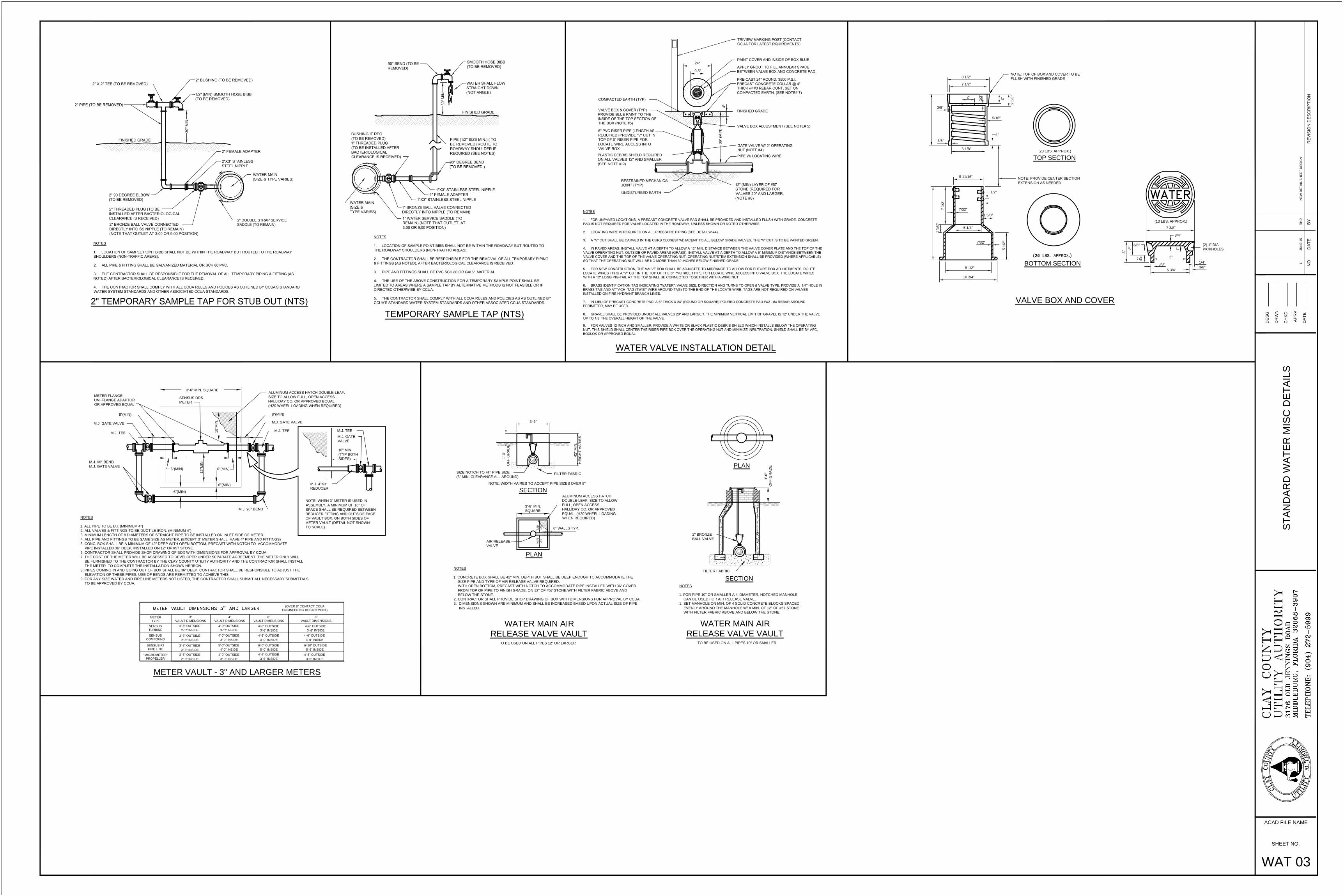
1 5
/8
"
3/8"
3/8"
5/16"
1/4"
3/8"
5 1/4"
8 1/2"
10 3/4"
7 1
/2
"
7/32"
5 11/16"
VALVE BOX AND COVER
3"
TOP SECTION
BOTTOM SECTION
5 1
/2
"
1 5/8"
1/2"
(23 LBS. APPROX.)
1"
7 3/8"
5 3/4"
3/4"
1"
1"
3/8"
2"
3/8"
5"
7/32"
(13 LBS. APPROX.)
7 1/2"
2"
6 1/8"
8 1/2"
2"
2 5
/8
"
1/2
"
3'-6"
42
" M
IN
.
HE
IG
HT
V
AR
IE
S
12"
MIN
.
12"
MIN
.
SIZE NOTCH TO FIT PIPE SIZE
(3" MIN. CLEARANCE ALL AROUND)
NOTE: WIDTH VAIRES TO ACCEPT PIPE SIZES OVER 8"
NOTES
1. CONCRETE BOX SHALL BE 42" MIN. DEPTH BUT SHALL BE DEEP ENOUGH TO ACCOMMODATE THE
SIZE PIPE AND TYPE OF AIR RELEASE VALVE REQUIRED,
WITH OPEN BOTTOM, PRECAST WITH NOTCH TO ACCOMMODATE PIPE INSTALLED WITH 36" COVER
FROM TOP OF PIPE TO FINISH GRADE, ON 12" OF #57 STONE,WITH FILTER FABRIC ABOVE AND
BELOW THE STONE.
2. CONTRACTOR SHALL PROVIDE SHOP DRAWING OF BOX WITH DIMENSIONS FOR APPROVAL BY CCUA.
3. DIMENSIONS SHOWN ARE MINIMUM AND SHALL BE INCREASED BASED UPON ACTUAL SIZE OF PIPE
INSTALLED.
WATER MAIN AIR
RELEASE VALVE VAULT
6" WALLS TYP.
NOTES
1. FOR PIPE 10" OR SMALLER A 4' DIAMETER, NOTCHED MANHOLE
CAN BE USED FOR AIR RELEASE VALVE.
2. SET MANHOLE ON MIN. OF 4 SOLID CONCRETE BLOCKS SPACED
EVENLY AROUND THE MANHOLE W/ A MIN. OF 12" OF #57 STONE
WITH FILTER FABRIC ABOVE AND BELOW THE STONE.
TO BE USED ON ALL PIPES 12" OR LARGER
FILTER FABRIC
FILTER FABRIC
3'-6" MIN.
SQUARE
ALUMINUM ACCESS HATCH
DOUBLE-LEAF, SIZE TO ALLOW
FULL, OPEN ACCESS.
HALLIDAY CO. OR APPROVED
EQUAL. (H20 WHEEL LOADING
WHEN REQUIRED)
TO BE USED ON ALL PIPES 10" OR SMALLER
WATER MAIN AIR
RELEASE VALVE VAULT
3'-6" MIN. SQUARE
METER VAULT - 3" AND LARGER METERS
NOTES
1. ALL PIPE TO BE D.I. (MINIMUM 4")
2. ALL VALVES & FITTINGS TO BE DUCTILE IRON. (MINIMUM 4")
3. MINIMUM LENGTH OF 8 DIAMETERS OF STRAIGHT PIPE TO BE INSTALLED ON INLET SIDE OF METER.
4. ALL PIPE AND FITTINGS TO BE SAME SIZE AS METER. (EXCEPT 3" METER SHALL HAVE 4" PIPE AND FITTINGS)
5. CONC. BOX SHALL BE A MINIMUM OF 42" DEEP WITH OPEN BOTTOM, PRECAST WITH NOTCH TO ACCOMMODATE
PIPE INSTALLED 36" DEEP, INSTALLED ON 12" OF #57 STONE.
6. CONTRACTOR SHALL PROVIDE SHOP DRAWING OF BOX WITH DIMENSIONS FOR APPROVAL BY CCUA.
7. THE COST OF THE METER WILL BE ASSESSED TO DEVELOPER UNDER SEPARATE AGREEMENT. THE METER ONLY WILL
BE FURNISHED TO THE CONTRACTOR BY THE CLAY COUNTY UTILITY AUTHORITY AND THE CONTRACTOR SHALL INSTALL
THE METER TO COMPLETE THE INSTALLATION SHOWN HEREON.
8. PIPES COMING IN AND GOING OUT OF BOX SHALL BE 36" DEEP. CONTRACTOR SHALL BE RESPONSIBLE TO ADJUST THE
ELEVATION OF THESE PIPES, USE OF BENDS ARE PERMITTED TO ACHIEVE THIS.
9. FOR ANY SIZE WATER AND FIRE LINE METERS NOT LISTED, THE CONTRACTOR SHALL SUBMIT ALL NECESSARY SUBMITTALS
TO BE APPROVED BY CCUA.
METER
TYPE
SENSUS
TURBINE
SENSUS
COMPOUND
"McCROMETER"
PROPELLER
3"
VAULT DIMENSIONS
4"
VAULT DIMENSIONS
6"
VAULT DIMENSIONS
8"
VAULT DIMENSIONS
3'-6" OUTSIDE
2-'6" INSIDE
3'-6" OUTSIDE
2'-6" INSIDE
3'-6" OUTSIDE
2'-6" INSIDE
4'-0" OUTSIDE
3-'0" INSIDE
4'-0" OUTSIDE
3'-0" INSIDE
4'-0" OUTSIDE
3'-0" INSIDE
4'-6" OUTSIDE
3'-6" INSIDE
4'-6" OUTSIDE
3'-0" INSIDE
4'-6" OUTSIDE
3'-6" INSIDE
4'-6" OUTSIDE
3'-6" INSIDE
4'-6" OUTSIDE
3'-6" INSIDE
1'-0
"
OF
F G
RA
DE
1'-0
"
OF
F G
RA
DE
M.J. GATE VALVE
M.J. TEE
M.J. 90° BEND
M.J. GATE VALVE
SENSUS F2
FIRE LINE
3'-6" OUTSIDE
2'-6" INSIDE
5'-0" OUTSIDE
4'-0" INSIDE
6'-0" OUTSIDE
5'-0" INSIDE
4'-6" OUTSIDE
3'-0" INSIDE
6'-10" OUTSIDE
5'-6" INSIDE
(OVER 8" CONTACT CCUA
ENGINEERING DEPARTMENT)
16" MIN.
(TYP BOTH
SIDES)
M.J. GATE
VALVE
M.J. TEE
M.J. 4"X3"
REDUCER
NOTE: WHEN 3" METER IS USED IN
ASSEMBLY, A MINIMUM OF 16" OF
SPACE SHALL BE REQUIRED BETWEEN
REDUCER FITTING AND OUTSIDE FACE
OF VAULT BOX, ON BOTH SIDES OF
METER VAULT (DETAIL NOT SHOWN
TO SCALE).
ALUMINUM ACCESS HATCH DOUBLE-LEAF,
SIZE TO ALLOW FULL, OPEN ACCESS.
HALLIDAY CO. OR APPROVED EQUAL.
(H20 WHEEL LOADING WHEN REQUIRED)
8"(MIN)
6"(MIN) 6"(MIN)
METER FLANGE,
UNI-FLANGE ADAPTOR
OR APPROVED EQUAL
SENSUS DRS
METER
12
"M
IN
.
6"(MIN)
6"(MIN)
M.J. 90° BEND
M.J. GATE VALVE
M.J. TEE
18
"M
IN
.
8"(MIN)
NOTE: TOP OF BOX AND COVER TO BE
FLUSH WITH FINISHED GRADE
NOTE: PROVIDE CENTER SECTION
EXTENSION AS NEEDED
(2) 1" DIA.
PICKHOLES
AIR RELEASE
VALVE
SECTION
PLAN
PLAN
SECTION
RE
VIS
IO
N D
ES
CR
IP
TIO
NB
YN
OD
AT
E
DA
TE
AP
RV
DR
WN
CH
KD
DE
SG
RH
DJU
NE
1
51
NE
W D
ET
AIL
S
HE
ET
D
ES
IG
N
SHEET NO.
ACAD FILE NAME
ST
AN
DA
RD
W
AT
ER
M
IS
C D
ET
AILS
WAT 03
2" BRONZE
BALL VALVE

TOP VIEW
S-SEW

DOUBLE RECLAIMED SERVICESLONG SINGLE RECLAIMED SERVICES SHORT SINGLE RECLAIMED SERVICES
RE
CL
AIM
ED
W
AT
ER
D
IS
TR
IB
UT
IO
N
SY
ST
EM
D
ET
AIL
S A
ND
S
PE
CIF
IC
AT
IO
NS
FINAL INSPECTION PROCEDURES
1" x 3" SCH 40 STAINLESS STEEL NIPPLE (ONLY ONE
1" SCH 80 FEMALE ADAPTER (SxFIPT)
1" x 6" SCH 40 PVC PIPE (PURPLE)
1" SCH 40 PVC PIPE (PURPLE)
1" LOCKING WING BALL VALVE (SEE TABLE ON WATER DETAILS SHEET)
8.
9.
6.
5.
4.
3.
2.
1.
1" x 6" SCH 80 PVC NIPPLE (TxT)
1" x 90 SCH 80 PVC ELL. (SxFIPT)7.
1" x 90 SCH 80 PVC ELL. (SxS)
1 1/2" x 3" SCH 40 STAINLESS STEEL NIPPLE (ONLY ONE
1 1/2" SCH 80 FEMALE ADAPTER (SxFIPT)
1" x 90 SCH. 80 BEND (SxS)
1"x 6" SCH. 80 NIPPLE (TxT)
1 1/2" SCH 40 PIPE (PURPLE)
6.
10.
9.
8.
7.
5.
4.
3.
2.
1.
1" LOCKING WING BALL VALVE (SEE TABLE ON WATER DETAILS SHEET)
1" x 3/4" BRASS BUSHING (TxFIPT)
1 1/2" BRONZE BALL VALVE (REQ'D. ONLY WHEN TAPPING MAIN UNDER PRESSURE)2A.
___x 1" STAINLESS STEEL TAPPING SADDLE,
(NO DUAL RANGE SADDLES ALLOWED)
2A. 1" BRONZE BALL VALVE (REQ'D. ONLY WHEN TAPPING MAIN UNDER PRESSURE)
10. 1" x 3/4" BRASS RED. BUSHING (Tx FIPT)
SIZE ON SIZE,
_____x 1 1/2" STAINLESS STEEL TAPPING SADDLE,
(NO DUAL RANGE SADDLES ALLOWED)SIZE ON SIZE,
11.
1" x 90 SCH 80 PVC BEND (SxT)
1" LOCKING WING BALL VALVE (SEE TABLE ON WATER DETAILS SHEET)
1-1/2" x 1" SCH 80 PVC REDUCING BUSHING (SxS), AS REQUIRED
12.
13.
1" x 6" SCH 80 PVC NIPPLE (TxT)
1-1/2" BRONZE BALL VALVE (REQ'D. ONLY WHEN TAPPING MAIN UNDER PRESSURE)
___X 1-1/2" STAINLESS STEEL TAPPING SADDLE
1-1/2" x 3" SCH 40 STAINLESS STEEL NIPPLE (ONLY ONE
1.
2A.
2.
5.
4.
6.
9.
8.
10.
7.
3.
(NO DUAL RANGE SADDLES ALLOWED)
1-1/2" SCH 80 PVC TEE (SxSxS)
1" x 90 SCH 80 PVC BEND (SxS)
1" x 12" SCH 40 PVC PIPE (PURPLE)
1" SCH 40 PVC PIPE (PURPLE)
1-1/2" SCH 80 PVC FEMALE ADAPTER
1-1/2" SCH 40 PVC PIPE (PURPLE)
REQ'D. WHEN TAPPING MAIN NOT UNDER PRESSURE)
REQ'D WHEN TAPPING MAIN NOT UNDER PRESSURE)
REQ'D. WHEN TAPPING MAIN NOT UNDER PRESSURE)
1" x 90 SCH. 80 BEND (SxT)
11.
14.
1" x 3/4" BRASS REDUCING BUSHING (Tx FIPT)
1 1/2" x 1" SCH. 80 RED. BUSHING (SxS)
11.
12.
1" SCH 40 PIPE (PURPLE)
RECLAIMED WATER
WE IRRIGATE WITH
2'-0
"
1'-6
"
2'-0"
1 3/4" LETTERING
12
"
NATURAL / FINISHED GRADE
3"
8"
UNIVERSAL RED SYMBOL
RECLAIMED WATER USE/WARNING SIGN
METER BOX - SEE CCUA APPROVED MATERIALS MANUAL.
METER BOX - SEE CCUA APPROVED MATERIALS MANUAL
METER BOX - SEE CCUA APPROVED MATERIALS MANUAL
METER VAULT - 3" AND LARGER METERS
12
" M
IN
.
18
" M
IN
.
4 1/4" DIA.
2 1/8" DIA.
1" LETTER
3/8"
3/4
"
9-3
/4
"
8-1
/2
"
19-1/4"
1/4
"
1-1
/8
"
17-7/8"
20-1/8"
19-1/2"
18-1/2" 1/4
"
9-3
/4
"
10-1/2"
10"
9"
1-1/8" R.
3"
4"
NOTE:
TOLERANCE SHOULD BE 1/16",
UNLESS OTHERWISE SPECIFIED,
MATERIAL: CAST IRON ASTM A48 CLASS 25B
COATING: PAINTED
WEIGHT: 46 LBS(SET)
ROME METER BOX & LID W/
TOUCH READ HOLE
1. ALL PIPE TO BE D.I.
2. ALL VALVES & FITTINGS TO BE DUCTILE IRON.
3. MINIMUM LENGTH OF 8 DIAMETERS OF STRAIGHT PIPE TO
BE INSTALLED ON INLET SIDE OF METER.
4. ALL PIPE AND FITTINGS TO BE SAME SIZE AS METER.
5. CONC. BOX SHALL BE 42" DEEP WITH OPEN BOTTOM,
PRECAST WITH NOTCH TO ACCOMMODATE PIPE INSTALLED
36" DEEP, INSTALLED ON 12" OF #57 STONE
6. Contractor SHALL PROVIDE SHOP DRAWING OF BOX WITH
DIMENSIONS FOR APPROVAL BY CCUA.
7. DIMENSIONS SHOWN ARE MINIMUM AND SHALL BE INCREASED
BASED UPON ACTUAL SIZE OF METER PROVIDED.
8. THE COST OF THE METER WILL BE ASSESSED TO DEVELOPER
UNDER SEPARATE AGREEMENT. THE METER ONLY WILL BE
FURNISHED TO THE CONTRACTOR BY THE CLAY COUNTY
UTILITY AUTHORITY AND THE CONTRACTOR SHALL INSTALL
THE METER TO COMPLETE THE INSTALLATION SHOWN HEREON.
01. INTENTION. It is the declared and acknowledged intention to secure a new reclaimed water distribution system, complete, in accordance
with the plans and specifications, and contract documents. All new work shall be in accordance with Clay County Utility Authority Details and
Specifications and Approved Materials Manual and Clay County Engineering Department Details and Specifications and any other Government
Regulatory Agency. All work shall conform to the above whether or not specifically called out or noted on plans.
02. GENERAL. All materials shall be new and unused. Materials shall be warranted by the Contractor as to materials, workmanship and
accuracy of As-Built drawings for a period of two years from the date of completion of the work or beneficial use of the facilities. Workmanship
shall be of good quality; i.e., mains shall be laid in a uniform alignment, fittings shall be properly restrained, trenches shall be properly excavated
and backfilled, valve boxes shall be adjusted to finished grade.
02.1 Contractor LICENSE AND APPROVAL. Utility reserves the right to approve or deny approval of Contractor prior to construction of any
on-site or off-site utility facilities. Contractor must hold a State Of Florida Underground Utility Contractors license, that named contracting
company being the one doing the work on project, and demonstrate acceptable experience in the field of utility construction.
3. SURVEYS. The Utility Contractor shall provide all surveys necessary for the layout and construction of the work of his contract.
4. EARTHWORK. Earthwork shall include all excavation, fill and backfill (hand/machine), compaction and rough grading of materials
encountered. No unsuitable materials clay, muck, or peat removed from pipe trenches are to be used for backfill. All fill or backfill shall be either
sand or sandy clay, free of roots, trash or other debris. All backfill alongside of and to a height twenty-four inches above all pipe shall be free of
clay or organic material, compacted by either hand or machine operation carefully to 98%. All other backfill shall be compacted by either hand or
machine operation carefully to 95% (outside of paving), 98% (under paving) of its optimum moisture content as determined by ASTM D698, latest.
Copies of compaction density test reports from a licensed testing agency shall be made available to CCUA if requested.
5. JOINT RESTRAINT. All fittings shall be properly and adequately restrained against lateral movement at all reclaimed water main tees,
crosses, valves, bends and fire hydrants. Restrainers shall be Uni-Flange Series 1300, 1350, 1390 or approved equal installed per manufacturer's
recommendations and Clay County Utility Authority Details and Specifications.
6. DUCTILE IRON PIPE. Ductile iron pipe shall conform to ANSI Specification A21.50 (AWWA C150) latest, "Thickness Design of Ductile Iron
Pipe", Table 50.5, laying condition Type 2, internal operating pressure of 250 p.s.i. for an 8-foot depth of cover, Class 51 minimum and shall be
ANSI A21.51 (AWWA C151), latest centrifugally cast pipe. Laying lengths shall be 20 feet or less, each length clearly marked with pressure rating,
thickness class, height of pipe without lining, length, and manufacturer. Ductile iron pipe for reclaimed water service shall be furnished with
cement lining per AWWA C110, C115 and C151. The pipe shall have design values of 60,000 PSI minimum tensile strength, and 42,000 p.s.i.
minimum yield strength. All ductile iron piping shall be wrapped with purple tape and stamped "Reclaimed Water" on at least two sides @ 12" o.c.
along pipe barrel. Ductile iron pipe for reclaimed water or service lines shall be used in any easement, right-of-way, between lots, and any
instance where a building foundation or other permanent appurtenance is within 10' of the reclaimed water main or a service line larger than 3".
7. DUCTILE IRON FITTINGS shall be C153 cement lined and suitable for the type and class of pipe to which connected. Gaskets shall be
suitable for reclaimed water service. Minimum working pressure shall be 150 p.s.i.
8. POLYVINYL CHLORIDE PIPE. Polyvinyl chloride pipe for reclaimed water mains 4 inch in diameter through 24", shall be PVC 1120,
Pressure Class 235 psi DR-18 (C900) PVC. Reclaim mains above 24 inch in diameter shall be Pressure Class 165 psi DR-25 (C900) PVC,
conforming to ASTM D-1784, D-2241, D-3139 and F-477, latest, or PVC C900, Class 165, DR-25, conforming to ASTM D-1784, Cell Class 12454,
ASTM F-477, ASTM D-3139, latest, and shall bear the seal of the National Sanitation Foundation. Pipe shall be Pantone Purple 522C and marked
on at least 2 sides with the word "RECLAIMED WATER" and at every 12" along the barrel of the pipe. Joint couplings shall be rubber gasketed,
push-on type conforming to ASTM D-2122.
9. STEEL CASING PIPE. Steel casing pipe shall be of size indicated on the Drawings and shall conform to ASTM A139, with a minimum
yield strength of 35,000 p.s.i.
10. POLYVINYL CHLORIDE (PVC 1120, SCHEDULE 40) PIPE shall comform to the requirements of ASTM D 1785. Fittings and threaded
nipples shall be Sch. 80 PVC. All piping smaller than 4" shall be Sch. 40 or Sch. 80 as detailed. Schedule 40 PVC pipe shall be Pantone purple
522C and marked "Reclaimed Water".
11. GATE VALVES AND VALVE BOXES. Gate valves shall be non-rising stem type and shall be suitable for a 200 p.s.i. non-shock working
pressure gate valves shall be mechanical joint, flanged or screwed. Gate valves shall have a 2" operating nut and open left. Gate valves shall
have joints suitable for the type of main on which installed. Valves 2" & 3" shall be bronze (distribution mains only). Gate valves 4" and larger shall
be iron body, bronze fitted with resilient seat. Valves shall be of DOMESTIC (American) manufacture and shall be those listed in CCUA Approved
Material Manual. Valves 16" and larger shall be AWWA C-515. Valve boxes with screw extensions shall be provided for all gate valves. Boxes
shall be of cast iron construction, 7/32" minimum wall thickness and shall be nontacky tar enamel coated. The word "RECLAIMED WATER" shall
be cast in the cover. Other valves smaller than 2" shall be heavy-duty bronze, ball valves, in lieu of a gate valve. Box covers to be primed and
painted Pantone Purple 522C.
12. RECLAIMED WATER METER BOXES. See CCUA Approved Materials Manual. Developer shall be responsible for installation of meter
boxes on all reclaimed water services as part of the reclaimed water main installation. All curb stops shall be adjusted to the proper elevation and
shall be accessible for the installation of the reclaimed water meter. The Contractor shall be required to open all boxes for the Authority's
inspector at the final inspection. A treated 6' - 6" long treated fence post marker shall be installed at the side of and centered on the meter box and
painted Pantone Purple 522C for identification.
13. CURB STOPS. Curb stops shall be cast bronze, inverted key stop, roundway, with check, lock wing type, for locking in the closed position.
See CCUA Approved Materials Manual.
14. PRESSURE REDUCING VALVES (when and where required) The pressure reducing valve shall maintain a constant delivery pressure as
part of the service to each residential irrigation system. Pressure reducing valves shall conform with the standard requirements of the ASSE (Std.
1003) and WPOA Uniform Plumbing Code. Approved model: Watts Series U5B or equal.
15. INSTALLATION. The minimum cover over top of reclaimed water main shall be 48" minimum. All lines and appurtenances shall be
thoroughly cleaned of all foreign matter before being lowered into the trench and shall be kept clean during laying operations by means of plugs or
other approved methods. All pipe shall be checked for defects before being lowered into the trench. Defective pipe shall not be used. Pipe found
to be defective after installation, shall be removed and replaced with sound pipe at no additional expense to the Owner. The full length of each
section of pipe shall rest solidly upon the pipe bed, with recesses excavated to accommodate the bells and joints. All pipe that has the grade or
joint disturbed after laying shall be removed and reinstalled. The pipe shall not be laid in water or when trench or weather conditions are
unsuitable for the work. All joints shall be cleaned of all foreign matter before making the joint. Fittings at bends in the pipe shall be properly
restrained with joint restrainers adequately sized to prevent movement and dislocating or blowing off when the line is under pressure. Service
laterals shall terminate at the point noted in the details. All reclaimed mains shall be installed with tracer wire per CCUA standard location wire
details.
16. SEPARATION OF RECLAIMED WATER MAINS. Maximum separation of reclaimed water lines and potable water lines shall be practiced.
A minimum horizontal separation of three feet, outside-to-outside, shall be maintained between reclaimed water mains and either potable water
mains or wastewater pipes. Reclaimed water mains crossing under water mains shall be laid to provide a minimum vertical separation of 18
inches between the invert of the upper pipe and the crown of the lower pipe. Where the minimum separation cannot be maintained, the crossing
shall be arranged such that the reclaimed water main pipe joints and potable water main joints are equidistant from the point of crossing with no
less than ten feet between joints. Alternatively, the reclaimed water main shall be placed in a sleeve to obtain the equivalent of the required ten
feet separation. Where there is no alternative to reclaimed water pipes crossing over a water main, the criteria for minimum separation between
lines and joints shall be required.
17. PIPE FLUSHING. All reclaimed water system piping shall be flushed with clean water utilizing full pipe diameter flushing. In cases where
the water supply is inadequate to flush the full pipe diameter, flushing shall occur to the extent of the water supply that is available. All flushing
must be contained.
18. TESTS. After the pipe is laid, the joints completed, and the trench backfilled, the pipe and appurtenances shall be subjected to a
Hydrostatic and Leakage test of 150 pounds per square inch for a period of at least two hours. During this period, all joints shall be inspected to
determine water tightness of the system. Any leaks detected shall be corrected. Tests shall be in accordance with the Clay County Utility
Authority's requirements and specifications. Curb and limerock may be installed after construction of the reclaimed water mains, however,
limerock priming cannot proceed until such time as the CCUA inspector approves the reclaimed water distribution system pressure test. This will
be strictly enforced. If the reclaimed water system is damaged during any of the operations prior to paving, a follow up test may be required by the
Clay County Utility Authority.
19. WARNING SIGN. Each development, subdivision, or commercial establishment, regardless of the number of buildings, shall install
reclaimed water use warning signs at the entrance or any other street or driveway entering any properties which use reclaimed water. The signs
shall meet the requirements of CCUA details and specifications. The signs shall be a requirement whether shown on plans or not. Direction of
locating those signs shall be given by the CCUA inspector on site.
20. POLYETHYLENE TUBING SERVICE LINES AND MAINS (2 INCH AND SMALLER):
Tubing shall be manufactured of PE 4710, High Density Polyethylene (HDPE), in accordance with AWWA C901,
ASTM D1248, ASTM D2239, ASTM D3737 and ASTM D3350. The tubing shall have a minimum working pressure of 250 psi. Polyethylene tubing
shall be copper tube size SDR-9 and shall be colored purple. HDPE pipe shall have ultraviolet (UV) inhibitors for protection against direct sunlight
for 1 year. Inserts for polyethylene tubing may be utilized, at Contractor's options, and, if used, shall be 316 stainless steel. The use of no-lead
brass couplings, tees and "Y" fittings are acceptable on poly service tubing, if not located under a roadway. Tubing shall be approved for use with
potable water by the National Sanitation Foundation (NSF-14) and shall be continuously marked at intervals of not more than four feet with the
following:
Nominal size
Pressure rating
NSF seal
Manufacturer's name or trademark
Standard dimension ratio
ASTM specification
S-RE1
OUTLINE SPECIFICATIONS FOR CONSTRUCTION
OF RECLAIMED WATER DISTRIBUTION SYSTEM
NOTE: ALL RECLAIMED WATER SERVICES ARE TO BE INSTALLED ON ONE LOT LINE AND POTABLE WATER SERVICES ARE TO BE INSTALLED ON THE
OTHER. THIS IS TO ALLOW SEPARATION OF THE TWO WATER SERVICES. SEWER SERVICES ARE TO BE INSTALLED AT THE MIDDLE OF THE LOT.
METER FLANGE,
UNI-FLANGE ADAPTOR
OR APPROVED EQUAL
CCUA
METER
MECH. JT.
GATE VALVE
ALUMINUM ACCESS HATCH
DOUBLE-LEAF, SIZE TO ALLOW FULL,
OPEN ACCESS.
MECH. JT. GATE VALVE
8"
MIN.
8"
MIN.
6"
MIN.
6"
MIN.
1/8" THK. ALUMINUM SHEET PANEL TO BE
WHITE REFLECTION VINYL SIGN W/ BLACK
LETTERS. POST TO BE PAINTED BLACK.
ATTACH SIGN TO POST W/ SS FASTENERS.
CONCRETE
POST ANCHOR
PRIOR TO FINAL ACCEPTANCE FOR OWNERSHIP, THE FOLLOWING MUST BE COMPLETED:
1. Reclaimed water services must be lowered and meter boxes installed, valve boxes must be set on all gate valves, recast concrete valve
box collar must be in place on all gate valves.
2. As-built drawings shall have been updated to accommodate the Clay County Utility Authority's comments (shall comply to the guidance
set forth in CCUA's `As-built Specifications Standards Manual`, which can be obtained from CCUA's website www.clayutility.org).
3. As-builts must be accepted by the Clay County Utility Authority.
4. All valves and single services should be scribed in curb and painted the correct color for each.
2"x 2"x 1/8"x 4'-6"
ALUM. POST
3,000 p.s.i. CONC.
5" 2"
SECTION
23.5"
OPENING
9.5"
#3 CONT.
5"
2"
PLAN
2"
2"
5" 2"
OPENING
9.5"2" 5"
PRECAST CONCRETE
VALVE BOX COLLAR
3'-0
"3
'-6
"
METER BOX
RECLAIMED WATER SVC.
10
" T
O 1
2"
PAINTED PURPLE
RECLAIMED SERVICE LOCATION POST
ALL SERVICES ARE TO BE CLEARLY MARKED BY A TREATED 6'-6" LONG MARKER POST PAINTED
PURPLE. ALL SERVICES ARE TO BE EXTENDED ABOVE GRADE UNTIL COMPLETION OF ALL
GRADING ACTIVITIES. ONCE FINAL ROAD GRADING IS COMPLETE, LOWER SERVICES BY CUTTING
OFF RISER 8" TO 10" BELOW FINAL GRADE AND INSTALL 90 BEND, NIPPLE AND LW BALL VALVE AT
THAT ELEVATION. SET METER BOX OVER ENTIRE HORIZONTAL SECTION OF SERVICE LINE FROM
LAST 90 BEND TO THE END OF THE CURB STOP. BOX TO BE REPOSITIONED WHEN THE METER IS
INSTALLED. MARKER POST TO BE INSTALLED ADJACENT TO AND LOCATED AT THE MID SECTION
OF THE METER BOX.
REPOSITION OF METER BOX
AFTER INSTALLATION OF METER
(BY OTHERS)
6'-6" LONG, TREATED FENCE POST
BRICK FOR METER BOX
SUPPORT (TYP.)
ABOUT FOUR SIDES
BRICK FOR METER BOX
SUPPORT (TYP.)
ABOUT FOUR SIDES
NOTE:
PRIOR TO FINAL INSPECTION, THE Contractor SHALL PROVIDE THE FOLLOWING : 1. The pressure test and flushing report.
2. The Engineer of Record certification to FDEP; this can be done with preliminary as-builts.
3. Preliminary as-builts showing at least the following: location of valves, mains, services and manholes.
4. All services and valves to be plainly marked with a treated fence post.
5. The reclaimed water use warning sign/signs shall be installed.
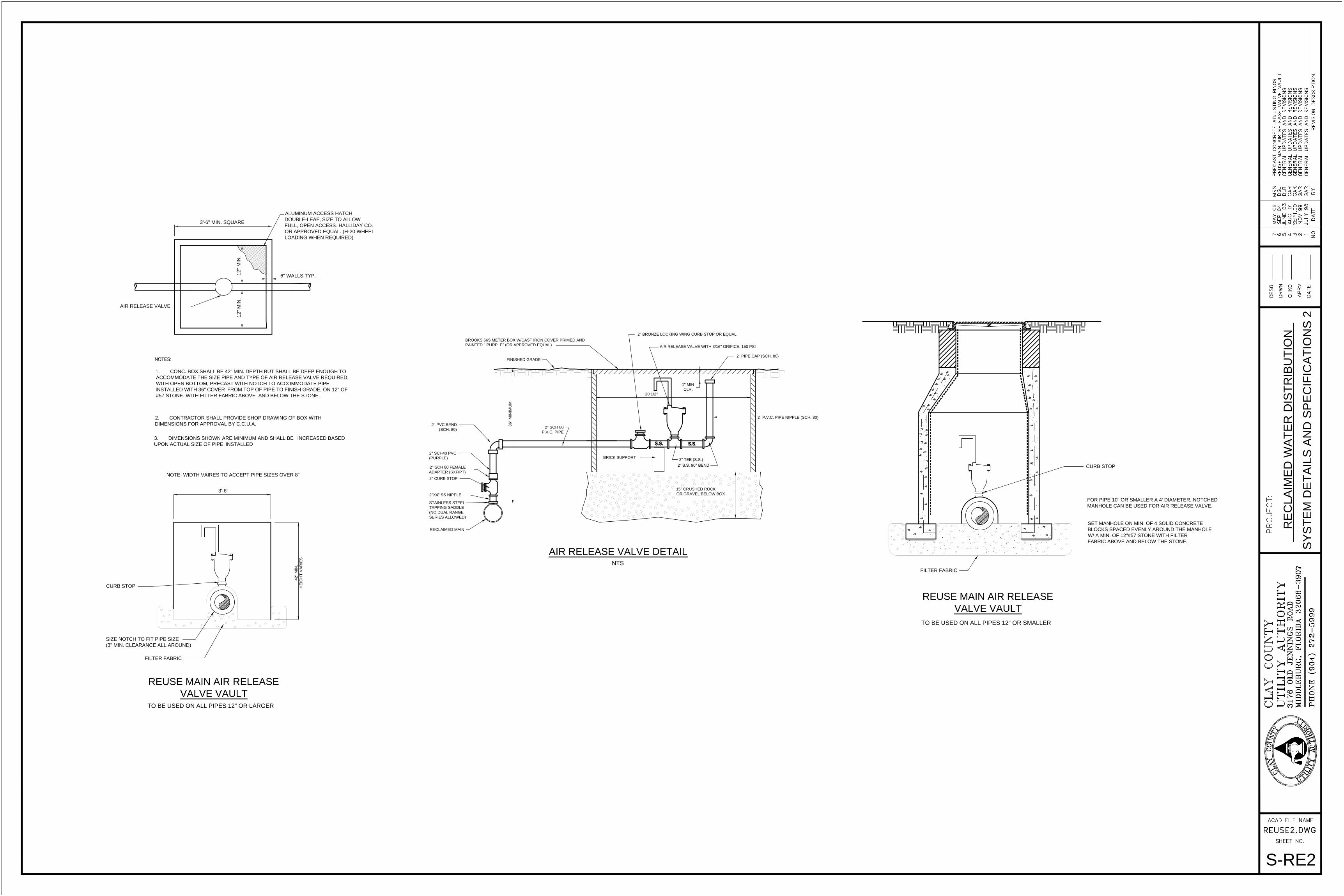
2" S.S. 90° BEND
36" M
IN
IM
UM
2" TEE (S.S.)
RECLAIMED MAIN
FINISHED GRADE
NTS
2''X4'' SS NIPPLE
20 1/2''
BRICK SUPPORT
SY
ST
EM
D
ET
AILS
A
ND
S
PE
CIF
IC
AT
IO
NS
2
RE
CLA
IM
ED
W
AT
ER
D
IS
TR
IB
UT
IO
N
FILTER FABRIC
FILTER FABRIC
SET MANHOLE ON MIN. OF 4 SOLID CONCRETE
BLOCKS SPACED EVENLY AROUND THE MANHOLE
W/ A MIN. OF 12"#57 STONE WITH FILTER
FABRIC ABOVE AND BELOW THE STONE.
TO BE USED ON ALL PIPES 12" OR SMALLER
FOR PIPE 10" OR SMALLER A 4' DIAMETER, NOTCHED
MANHOLE CAN BE USED FOR AIR RELEASE VALVE.
6" WALLS TYP.
REUSE MAIN AIR RELEASE
VALVE VAULT
3. DIMENSIONS SHOWN ARE MINIMUM AND SHALL BE INCREASED BASED
UPON ACTUAL SIZE OF PIPE INSTALLED
2. CONTRACTOR SHALL PROVIDE SHOP DRAWING OF BOX WITH
DIMENSIONS FOR APPROVAL BY C.C.U.A.
1. CONC. BOX SHALL BE 42" MIN. DEPTH BUT SHALL BE DEEP ENOUGH TO
ACCOMMODATE THE SIZE PIPE AND TYPE OF AIR RELEASE VALVE REQUIRED,
WITH OPEN BOTTOM, PRECAST WITH NOTCH TO ACCOMMODATE PIPE
INSTALLED WITH 36" COVER FROM TOP OF PIPE TO FINISH GRADE, ON 12" OF
#57 STONE. WITH FILTER FABRIC ABOVE AND BELOW THE STONE.
NOTE: WIDTH VAIRES TO ACCEPT PIPE SIZES OVER 8"
SIZE NOTCH TO FIT PIPE SIZE
(3" MIN. CLEARANCE ALL AROUND)
AIR RELEASE VALVE
12
" M
IN
.1
2" M
IN
.
42" M
IN
.
HE
IG
HT
V
AR
IE
S
3'-6"
3'-6" MIN. SQUARE
TO BE USED ON ALL PIPES 12" OR LARGER
REUSE MAIN AIR RELEASE
VALVE VAULT
S-RE2
AIR RELEASE VALVE DETAIL
2'' SCH 80 FEMALE
ADAPTER (SXFIPT)
2'' SCH40 PVC
(PURPLE)
2'' PVC BEND
(SCH. 80)
2" SCH 80
P.V.C. PIPE
15" CRUSHED ROCK
OR GRAVEL BELOW BOX
2" P.V.C. PIPE NIPPLE (SCH. 80)
2" PIPE CAP (SCH. 80)
AIR RELEASE VALVE WITH 3/16'' ORIFICE, 150 PSI
2" BRONZE LOCKING WING CURB STOP OR EQUAL
BROOKS 66S METER BOX W/CAST IRON COVER PRIMED AND
PAINTED '' PURPLE'' (OR APPROVED EQUAL)
STAINLESS STEEL
TAPPING SADDLE
(NO DUAL RANGE
SERIES ALLOWED)
1" MIN
CLR.
CURB STOP
CURB STOP
2'' CURB STOP
ALUMINUM ACCESS HATCH
DOUBLE-LEAF, SIZE TO ALLOW
FULL, OPEN ACCESS. HALLIDAY CO.
OR APPROVED EQUAL. (H-20 WHEEL
LOADING WHEN REQUIRED)

A A
CONCRETE
S-PCON
GENERAL NOTES:
TH
IS
S
HT
.
2'-6" M
IN
.
AB
OV
E G
RA
DE
SE
E N
OT
E 11
4"Ø SCH.40 ALUM. POSTS
SEE NOTE 11, THIS SHT.
LOW PROFILE CONTROL PANEL
CONDUIT SIZED FOR 40% CAPACITY, ONE MOTOR
CIRCUIT IN EACH SCH. 80 PVC CONDUIT
MUST BE SEALED WITH DUCT-SEAL ONLY
BUBBLER LINE TO BE 3/4" SCH.
80 PVC CONTINUOUS TO
CONTROL PANEL
*ATLANTIC COMPANIES AUTO DIALER SPECIFICATIONS:
FINISHED GRADE
OR TOP OF L.S.
POWER LINES IN SCH. 80 PVC
CONDUIT SIZED AS PER
NATIONAL ELECTRICAL CODE
GENERATOR RECEPTACLE
SEE ELECTRICAL SCHEMATIC
FOR TYPE
STAINLESS STEEL CONTROL
PANEL WITH NEMA 3R RATING
WATT-HOUR METER TO BE
GROUNDED TO 20 OHM
RESISTANCE OR LESS
(MOUNTED ON ALUM.
POST OPPOSITE OF
PANEL FRONT, SHOWN
ROTATED OUT OF
POSITION FOR CLARITY)
SEE PLAN THIS SHT.
HIGH LEVEL ALARM LIGHT W/
GUARD AND HORN
(MOUNTED ON ALUM. POST
OPPOSITE OF PANEL
FRONT, SHOWN ROTATED
OUT OF POSITION FOR
CLARITY) SEE PLAN THIS
SHT.
EACH PUMP STATION SHALL BE EQUIPPED WITH A DSC PC1616 MASTER CONTROL PANEL WITH LOCKED
METAL ENCLOSURE W/ BOX DIMENSIONS OF 12"X 12" X 4 1/2"; A DSC PKP-IKON OR A DSC PK-5501
ACCESS KEYPAD MOUNTED ON THE PANEL ENCLOSURE W/ DIMENSIONS NO GREATER THAN 4 3/4"X 4
3/4"X 1"; A 12 VOLT, 7 AMP BACK-UP BATTERY; A TRANSFORMER (16.5 VAC) OUTSIDE BOX IN ELECTRICAL
OUTLET; RESOLUTION PRODUCTS RE927X-03-00 OR RE928X-03-00 CELL COMMUNICATORS; ELECTRICAL
SURGE PROTECTOR (OUTSIDE BOX IN ELECTRICAL OUTLET); AND ALL MISCELLANEOUS HARDWARE
FOR A COMPLETE AND OPERATING SYSTEM.
ALL COMPONENTS LISTED TO BE ENCLOSED IN THE ALARM PANEL BOX WITH EXCEPTION OF THE
TRANSFORMER, THE ELECTRICAL SURGE PROTECTOR, CELLULAR COMMUNICATOR (INSIDE THE
WEATHER PROOF ENCLOSURE) AND THE CONTROL PANEL KEYPAD (TO BE MOUNTED DIRECTLY ONTO
THE ALARM PANEL ENCLOSURE).
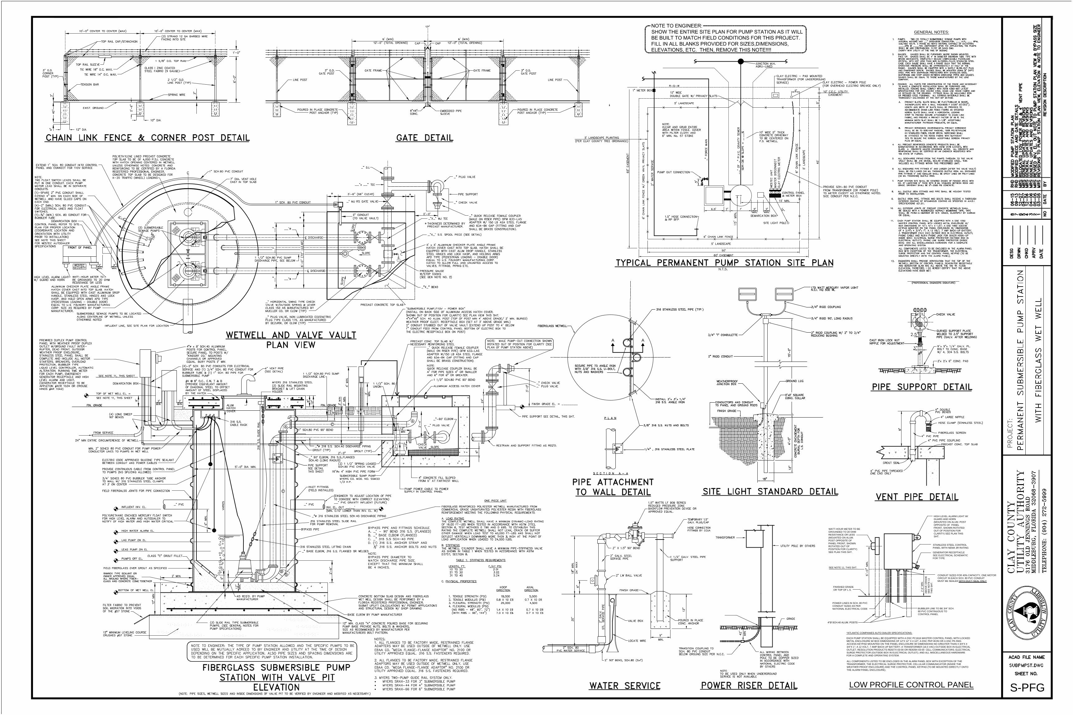
GENERAL NOTES:
A A
FIBERGLASS
S-PFG
TH
IS
S
HT
.
2'-6" M
IN
.
AB
OV
E G
RA
DE
SE
E N
OT
E 11
4"Ø SCH.40 ALUM. POSTS
SEE NOTE 11, THIS SHT.
LOW PROFILE CONTROL PANEL
CONDUIT SIZED FOR 40% CAPACITY, ONE MOTOR
CIRCUIT IN EACH SCH. 80 PVC CONDUIT
MUST BE SEALED WITH DUCT-SEAL ONLY
BUBBLER LINE TO BE 3/4" SCH.
80 PVC CONTINUOUS TO
CONTROL PANEL
*ATLANTIC COMPANIES AUTO DIALER SPECIFICATIONS:
FINISHED GRADE
OR TOP OF L.S.
POWER LINES IN SCH. 80 PVC
CONDUIT SIZED AS PER
NATIONAL ELECTRICAL CODE
GENERATOR RECEPTACLE
SEE ELECTRICAL SCHEMATIC
FOR TYPE
STAINLESS STEEL CONTROL
PANEL WITH NEMA 3R RATING
WATT-HOUR METER TO BE
GROUNDED TO 20 OHM
RESISTANCE OR LESS
(MOUNTED ON ALUM.
POST OPPOSITE OF
PANEL FRONT, SHOWN
ROTATED OUT OF
POSITION FOR CLARITY)
SEE PLAN THIS SHT.
HIGH LEVEL ALARM LIGHT W/
GUARD AND HORN
(MOUNTED ON ALUM. POST
OPPOSITE OF PANEL
FRONT, SHOWN ROTATED
OUT OF POSITION FOR
CLARITY) SEE PLAN THIS
SHT.
EACH PUMP STATION SHALL BE EQUIPPED WITH A DSC PC1616 MASTER CONTROL PANEL WITH LOCKED
METAL ENCLOSURE W/ BOX DIMENSIONS OF 12"X 12" X 4 1/2"; A DSC PKP-IKON OR A DSC PK-5501
ACCESS KEYPAD MOUNTED ON THE PANEL ENCLOSURE W/ DIMENSIONS NO GREATER THAN 4 3/4"X 4
3/4"X 1"; A 12 VOLT, 7 AMP BACK-UP BATTERY; A TRANSFORMER (16.5 VAC) OUTSIDE BOX IN ELECTRICAL
OUTLET; RESOLUTION PRODUCTS RE927X-03-00 OR RE928X-03-00 CELL COMMUNICATORS; ELECTRICAL
SURGE PROTECTOR (OUTSIDE BOX IN ELECTRICAL OUTLET); AND ALL MISCELLANEOUS HARDWARE
FOR A COMPLETE AND OPERATING SYSTEM.
ALL COMPONENTS LISTED TO BE ENCLOSED IN THE ALARM PANEL BOX WITH EXCEPTION OF THE
TRANSFORMER, THE ELECTRICAL SURGE PROTECTOR, CELLULAR COMMUNICATOR (INSIDE THE
WEATHER PROOF ENCLOSURE) AND THE CONTROL PANEL KEYPAD (TO BE MOUNTED DIRECTLY ONTO
THE ALARM PANEL ENCLOSURE).

PUMP STATION - SECTION
GENERAL NOTES
__" D.I. SLUDGE SHOE
GROUT
6" MIN.
(ENGINEER TO SIZE WETWELL)
4'-6"
15'-0" A
BO
VE
G
RA
DE
POWER RISER DETAIL
42"
PUMP STATION BLDG. - ELEVATION
PUMP STA. INV. EL.
8"
TRANSFORMER
SLA
B
10"
4"
4'-4"
5'-4"
S.S. HINGES
MIN
.
GRADE
UTILITY POLE BY OTHER
ENGINEER TO SIZE WETWELL
PUMP STATION - PLAN
6'-0"
8'-0"
PA
NE
L
CO
NT
RO
L
3/4" RIGID 90°, LONG RADIUS
3/4" RIGID COUPLING
LEAD PUMP ON EL.
ALL PUMPS OFF EL.
12"
LAG PUMP ON EL.
HWL ALARM EL.
INV. EL.
PROVIDE 2 EXTRA #4's ON EACH SIDE OF OPENINGS
#4 HORIZ. BARS @ 9" O.C. E.W. TOP & BOT.
BOOT ADAPTER SEAL W/ NON-SHRINK GROUT
__" PVC GRAVITY INFLUENT
2" RIGID CONDUIT
8"
2" BAR CHANNEL
12"
3/4" 'T' CONDULETTE
_" 90° BEND
TOP OF CONC. EL.
3'-0"
8'-0"
6'-0"
12"
INV. EL. OUT __.__' (MIN. 0.10'
LOWER THAN INV. EL. IN)
(ENGINEER TO ADJUST LOCATION OF PIPE TO
COINCIDE WITH CORRECT ELEVATION)
__" PVC GRAVITY INFLUENT (FUTURE)
PUMP STATION SITE PLAN
ENGINEER TO PROVIDE DETAIL PUMP STATION SITE PLAN AS SHOWN ON PLAN SHEETS, INCLUDING
FENCING, LANDSCAPING, DRIVEWAY, ENTRANCE ROAD IF APPLICABLE, WATER SERVICE, ELECTRICAL
SERVICE/TRANSFORMER, UNDERGROUND SEWER MAIN ALIGNMENT TO FIRST MANHOLE OUT OF PUMP
STATION. PUMP STATION AND MANHOLE "DO NOT" REQUIRE LINER.
WATER SERVICE
1.5" 90° BEND, SCH.80 (SxT)
MIN.
9"
30
"
6"
24
" M
AX
18
" M
IN
.
FINISH GRADE
2" LW BALL VALVE
12
"
2" X 1.5" BEND
VALVE BOX2" G
AL
V.
ST
L. S
ER
VIC
E P
IP
E
2" SCH. 80
PVC WATER SERVICE
LOCATE WIRE
S-TAG
DA
VID
J. B
OL
AM
, P
.E
.
FL
. L
IC
EN
SE
#
4
24
80
_"X_" INCREASING
90° BEND
10"
SLA
B
_" D.I.
PIPE
_"x_"x_"
TEE
_" CHECK
VALVE
_" PLUG
VALVE
_" 90°
BEND, L.R.
_"x_"x_"
TEE
_" D.I.
PIPE
_" PLUG
VALVES
_" CHECK
VALVES
_" 90°
BENDS, L.R.
_" 90°
BEND, L.R.
NOTE: ENGINEER TO SIZE SUCTION
AND DISCHARGE PIPE. PIPE SIZES
SHOWN HEREON ARE TYPICAL
APPLICATION. IF DIFFERENT SIZES
ARE REQ'D., MODIFICATION TO THE
PUMP HOUSING DIMENSIONS TO
ACCOMMODATE LARGER PIPE SIZES
WILL BE REQ'D.
4" QUICK RELEASE
COUPLER, OPW 633-LAS
ADAPTER W/150 LB. ASA
STEEL FLANGE AND 634-
BK CAP (FITTING AND CAP
SHALL BE BRASS CONST.)
6" MIN. LEVELING COURSE OF COMPACTED
GRAVEL (#57) STONE. IN AREAS WHERE
MANHOLE LOCATIONS MAY IMPACT PAVING, #57
STONE SHALL BE COVERED W/ A FILTER FABRIC
IN A FASHION AS TO PREVENT SOIL MIGRATION
INTO VOIDS WITHIN THE #57 STONE.
#4 HORIZ. BARS @ 9" O.C. E.W.
CENTERED IN BASE
#4 DOWELS @ 12"
O.C. RADIALLY
__" SCH.40 S.S. SUCTION
LINE (2 REQUIRED)
POLYURETHANE ENCASED MERCURY FLOAT SWITCH
FOR HIGH LEVEL ALARM AND AUTODIALER TO
NOTIFY OF HIGH WATER AND HIGH WATER CRITICAL
3/4" SCH.80 BUBBLER
TUBING TO BE ATTACHED
TO WALL ON 3' CTR. W/
316 STRAPS
MANHOLE RING & COVER
U.S. FOUNDRY NO. 1307E
ASTM C-478 PRECAST SECTIONS
WITH A MIN. STEEL AREA OF 0.18
SQ. IN./LF, E.W.
APPROVED PREMOLDED JOINT SEALER
W/PROTECTIVE WRAPPER AT ALL JOINTS
(RAM-NEK OR APPROVED EQUAL)
NOTE TO ENGINEER: THE TYPE OF PUMP STATION ALLOWED AND THE SPECIFIC PUMPS TO BE USED WILL
BE MUTUALLY AGREED TO BY ENGINEER AND UTILITY AT THE TIME OF DESIGN DEPENDING ON THE
SPECIFIC APPLICATION. ALSO PIPE SIZES AND SPACING DIMENSIONS ARE TO BE DETERMINED FOR EACH
SPECIFIC PUMP STATION INSTALLATION.
1. SYSTEM TO INCLUDE WESTEC SECURITY SYSTEM WITH INDEPENDENT FLOAT
CONTROL AND TELEPHONE DIALER SYSTEM, TELEPHONE LINE BY OWNER.
2. SITE LOCATION OF LIFT STATION, CONTROL PANEL AND GENERATOR SHALL
BE ABOVE THE 100 YEAR STORM ELEVATION.
ALL WIRING BETWEEN
CONTROL PANEL AND POLE
TO BE COPPER SIZED IN
ACCORDANCE WITH
NATIONAL ELECTRIC CODE
TRANSITION COUPLING TO SCH.
80 PVC CONDUIT BELOW
GROUND SIZE PER N.E.C.
PROVIDE GALV. STEEL PIPE
CONDUIT ABOVE GROUND
SIZE PER N.E.C.
PROVIDE 8'MIN. EXCESS
SERVICE CABLE FROM
WEATHER HEAD TO
TRANSFORMER
GORMAN-RUPP
COMPANY PUMPS
W/V-BELT DRIVE (2
REQUIRED) MIN. 150
GPM AT 90' TDH (PUMPS
SHALL BE DESIGNED
FOR APPROPRIATE
HEAD AND FLOW
CONDITIONS, IF ABOVE
MINIMUM
ELECTRIC
METER &
MAIN
500 WATT QUARTZ LIGHT
N.C.I. HQ 500 WL
2" RIGID COUPLING W/ 2" TO
3/4" REDUCING BUSHING
ROOF MUST BE CROWNED
TO ELIMINATE WATER
ACCUMULATION
ATTACH LIGHT
STANDARD TO
EXTERIOR
OF BLDG.
1/4" PLATE
REINFORCE
AS REQ'D.
HASP FOR
PADLOCKS
1/4" FLOOR
PLATE
4" CHANNEL
BASE
1.5" WATTS LF909 SERIES
REDUCED PRESSURE ZONE
BACKFLOW PREVENTION DEVICE
OR APPROVED EQUAL.
HOSE CONNECTION
FITTINGS BY CCUA
1.5" GALV. STEEL PIPE
SUPPORT
TEMP 1.5" GALV. CAP/PLUG
2" GALV. STEEL
SERVICE PIPE
POURED IN PLACE
CONC. ANCHOR
NOTE: THIS PLAN IS FOR INFORMATIONAL PURPOSES ONLY.
EXPLICIT APPROVAL OF PLANS BY THE UTILITY AUTHORITY IS
REQUIRED PRIOR TO ANY CONSTRUCTION.
STATION CONTROLS DETAIL - SIDE VIEW
60" M
AX
.
GROUND
EXHAUST FAN
GENERATOR RECEPTACLE
WESTEC
PANEL
SERVICE ENTRANCE
RATED BREAKERS,
MASTER DISCONNECT
IN NEMA 4X 316
STAINLESS STEEL
ENCLOSURE
CONTROL
PANEL
CONTROL PANEL MOUNTED
ON SIDE OF PUMP BLDG.
HORN AND HORN SILENCER
MOUNTED ON SIDE OF PANEL
ALARM LIGHT MOUNTED
ON SIDE OF PANEL
LIGHT STANDARD
MOUNTED TO
EXTERIOR OF PUMP
BUILDING
FLOURESCENT
LIGHT W/GUARD
(INSIDE OF
BUILDING)
WATT-HOUR METER
MOUNTED ON BLDG.
2'-6"
MIN
.
*ATLANTIC COMPANIES AUTO DIALER SPECIFICATIONS:
EACH PUMP STATION SHALL BE EQUIPPED WITH A DSC PC1616 MASTER CONTROL
PANEL WITH LOCKED METAL ENCLOSURE W/ BOX DIMENSIONS OF 12"X 12" X 4 1/2"; A
DSC PKP-IKON OR A DSC PK-5501 ACCESS KEYPAD MOUNTED ON THE PANEL
ENCLOSURE W/ DIMENSIONS NO GREATER THAN 4 3/4"X 4 3/4"X 1"; A 12 VOLT, 7 AMP
BACK-UP BATTERY; A TRANSFORMER (16.5 VAC) OUTSIDE BOX IN ELECTRICAL
OUTLET; RESOLUTION PRODUCTS RE927X-03-00 OR RE928X-03-00 CELL
COMMUNICATORS; ELECTRICAL SURGE PROTECTOR (OUTSIDE BOX IN ELECTRICAL
OUTLET); AND ALL MISCELLANEOUS HARDWARE FOR A COMPLETE AND OPERATING
SYSTEM.
ALL COMPONENTS LISTED TO BE ENCLOSED IN THE ALARM PANEL BOX WITH
EXCEPTION OF THE TRANSFORMER, THE ELECTRICAL SURGE PROTECTOR,
CELLULAR COMMUNICATOR (INSIDE THE WEATHER PROOF ENCLOSURE) AND THE
CONTROL PANEL KEYPAD (TO BE MOUNTED DIRECTLY ONTO THE ALARM PANEL
ENCLOSURE).

NOTE:
QUICK RELEASE COUPLER SHALL BE
4" FOR PIPE SIZES 8" OR SMALLER
AND 6" FOR 10" OR GREATER.
BOTTOM OF WET WELL EL.
PUMPS OFF EL.
(NOTE: PIPE SIZES, WETWELL SIZES AND INSIDE DIMENSIONS OF VALVE PIT TO BE VERIFIED BY ENGINEER AND MODIFIED AS NECESSARY.)
12
" M
IN
.
12
"
CLASS "C" GROUT FILLET
(TYP)
12"
6"
BASE ELBOW BY PUMP MANUFACTURER
316 STAINLESS STEEL LIFTING CHAIN
2'-6
"
SEE NOTE 12, THIS SHEET
SEE NOTE 11, THIS SHEET
FROM SERVICE
TOP OF WET WELL EL. =
LEAD PUMP ON EL.
LAG PUMP ON EL.
HIGH WATER ALARM EL.
INFLUENT INV. EL.
FIN. GRADE
_" PLUG VALVE
(2
) 3
16
S
.S
. G
UID
E R
AIL
6" M
IN
.
_" PVC
5'-0" DIA. MIN.
_"Ø 316 STAINLESS STEEL SCH.40 DISCHARGE PIPING
_" PVC
16"Øx 4" HIGH PVC PIPE FORM
_"Ø 316 S.S. SCH.40 DISCHARGE PIPING
GROUT (TYP)
2'-0"
GROUT (TYP)
MIN
12"
SLOPE
8"
INFLUENT LINE, SEE SITE PLAN FOR LOCATION
FIN. GRADE
8"
12
"
1 1/2" SCH.80 UNION
1 1/2" SCH.80 PVC 90° BEND
_"-90° ELBOW
SITE LIGHT STANDARD DETAIL
3/4" 'T' CONDULETTE
PIPE ATTACHMENT TO WALL DETAIL
RESTRAIN AND SUPPORT FITTING AS REQ'D.
1/4" , 316 STAINLESS STEEL PLATE
S E C T I O N A - A
PIPE SUPPORT SEE DETAIL, THIS SHT.
FINISH GRADE EL. = ________
3'-0
"
3/8" 316 S.S. NUTS AND BOLTS
P L A N
FINISH GRADE
316 S.S. ANGLE IRON
INSTALL 3"x 3"x 1/4"
AA
2" RIGID CONDUIT
12"
18"
4'-0"
GROUND LUG
3/4" RIGID 90°, LONG RADIUS
15'-0"
FIBERGLASS
SECURITY
WESTEC
FRONT OF PANEL
6'-0" (7
2" C
LE
AR
)
C DISCHARGE
S
L
O
P
E
SLOPE
C DISCHARGE
S
L
O
P
E
__"x __" TEE
5'-6" (66" CLEAR)
_" D.I.
TYPICAL PERMANENT PUMP STATION SITE PLAN
CLAY ELECTRIC
PAD MOUNTED
TRANSFORMER
(FOR UNDERGROUND
SERVICE)
12' WIDE
DOUBLE GATE W/ PRIVACY SLATS
10' WIDE 5" THICK
CONCRETE DRIVEWAY
TO BE CENTERED ON
P.S. WETWELL
2" W
AT
ER
S
ER
VIC
E
65' E
AS
EM
EN
T
6' C
HA
IN
L
IN
K F
EN
CE
W
/ G
RE
EN
V
IN
YL
P
RIV
AC
Y S
LA
TS
__
' O
F _" P
.V
.C
. G
RA
VIT
Y S
EW
ER
PRECAST CONCRETE TOP SLAB
_"X_" BEND
2'-0"
_"X_" MJ TEE
_" CHECK VALVE
PIPE SUPPORT
N.T.S.
50'
60' EASEMENT
6' CHAIN LINK FENCE
5' LANDSCAPE
PUMP OUT CONNECTION
15
' M
IN
.
6.5'2'
SITE LIGHT POLE
7'
1
0
'
3'
15' MIN.
5' LANDSCAPE PLANTING
(PER CLAY COUNTY TREE ORDINANCE)
SD
R-26
@
S
LO
PE
=
_._
_
_" F
OR
CE
M
AIN
1" METER BOX
R-O-W
6' C
HA
IN
L
IN
K F
EN
CE
3/4" RIGID COUPLING
PROVIDE SCH-80 PVC CONDUIT
FROM TRANSFORMER (OR POWER
POLE) TO METER EXCEPT AS
OTHERWISE NOTED.
SIZE CONDUIT PER N.E.C.
CLAY ELECTRIC
POWER POLE
(FOR OVERHEAD
ELECTRIC SERVICE ONLY)
5' L
AN
DS
CA
PE
45'
5'
(PROFESSIONAL ENGINEERS SIGNATURE)
GENERAL NOTES:
(4)-2" SCH. 80 PVC CONDUITS FOR ELECTRICAL
SERVICE AND (1) 3/4" SCH. 80 PVC CONDUIT FOR
BUBBLER TUBE & (1) 1" SCH. 80 PIPE FOR
SUBMERSIBLE PUMP
(1)-SPARE 2" PVC CONDUIT SHALL
EXTEND 4" MIN. ON EACH SIDE OF
WETWELL AND HAVE GLUED CAPS
ON EACH END.
(4)-2" (MIN.) SCH. 80 PVC CONDUIT FOR
ELECTRICAL LINES AND FLOAT
SWITCHES.
(1)-
3
4
" (MIN.) SCH. 80 CONDUIT FOR
BUBBLER TUBE
NOTE:
TWO FLOAT SWITCH LEADS SHALL BE PUT IN ONE
CONDUIT. EACH PUMP MOTOR LEAD SHALL BE IN
SEPARATE CONDUITS.
INLET FITTINGS
(FIELD INSTALLED)
(ENGINEER TO ADJUST LOCATION OF PIPE
TO COINCIDE WITH CORRECT ELEVATION)
__" PVC GRAVITY INFLUENT (FUTURE)
INV. EL. OUT __.__'
(MIN. 0.10' LOWER THAN INV. EL. IN)
BYPASS PIPE
BYPASS PIPE AND FITTINGS SCHEDULE
A. _" - 90° BEND 316 S.S. (FLANGED)
B. _" BASE ELBOW (FLANGED)
C. _" 316 S.S SCH-40 PIPE
D. (1) 316 S.S. ANCHOR STRAP AND
1
2
" 316 S.S. ANCHOR BOLTS AND NUTS
NOTE:
BYPASS PIPE DIAMETER TO
MATCH DISCHARGE PIPE SIZE.
EXCEPT THAT THE MINIMUM SHALL
BE 4 INCHES.
2" CONDUIT (TO VALVE VAULT)
1" CONDUIT (TO CONTROL PANEL)
EXTEND 1" SCH. 80 CONDUIT INTO CONTROL
PANEL AND CONNECT FOR 110V SERVICE
12
"
4' M
IN
.
2' M
IN
3'
MIN
.
1" SCH.80 PVC CONDUIT
2" SCH.80 PVC CONDUIT
(2) LONG SWEEP
90° BENDS
3' M
IN
.
ELECTRIC CODE APPROVED
SILICONE TYPE SEALANT
BETWEEN CONDUIT AND
POWER CABLES
2'-6
"
MIN
.
2" SCH.80 PVC 90° BEND
1" SCH.80 PVC 90° BEND
SUBMERSIBLE PUMP 2" SCH. 80
CONDUIT PIPE FOR POWER CABLE
FLOW
FLO
W
5' LANDSCAPE
5'
10' C.E.C. UTILITY
EASEMENT
_" BASE ELBOW, 316 S.S. FLANGED OR WELDED
_" MJ RS GATE VALVE
MYER 316 STAINLESS STEEL
2 SLIDE RAIL MOUNTING
BRACKET & LIFT CHAIN
HOLDER
NOTES:
1. ALL FLANGES TO BE FACTORY MADE. RESTRAINED
FLANGE ADAPTERS MAY BE USED OUTSIDE OF
WETWELL ONLY. USE EBAA CO. "MEGA FLANGE-FLANGE
ADAPTOR" NO. 2100 OR UTILITY APPROVED EQUAL. 316
S.S. FASTENERS REQUIRED.
2. ALL FLANGES TO BE FACTORY MADE. RESTRAINED
FLANGE ADAPTORS MAY BE USED OUTSIDE OF WETWELL
ONLY. USE EBAA CO. "MEGA FLANGE-FLANGE ADAPTOR"
NO. 2100 OR UTILITY APPROVED EQUAL. 316 S.S.
FASTENERS REQUIRED.
3. MYERS TWO-PUMP GUIDE RAIL SYSTEM ONLY.
MYERS SRAX-33 FOR 3" SUBMERSIBLE PUMP
MYERS SRAX-44 FOR 4" SUBMERSIBLE PUMP
MYERS SRAX-66 FOR 6" SUBMERSIBLE PUMP
CLASS "A" CONCRETE POURED BASE FOR SECURING PUMP BASE
PROVIDE NUTS, BOLTS & WASHERS, SIZE AS RECOMMENDED BY
MANUFACTURER PER MANUFACTURERS BOLT PATTERN.
_" CHECK VALVE
_" PLUG VALVE
_" QUICK RELEASE FEMALE COUPLER
(MALE ON RISER PIPE) OPW 633-LAS
ADAPTER W/150 LB ASA STEEL FLANGE
AND 634-BK CAP (FITTING AND CAP
SHALL BE BRASS CONSTRUCTION).
2" CONDUIT
(TO VALVE VAULT)
1" SCH. 80 PVC CONDUIT
POLYETHYLENE LINED PRECAST CONCRETE TOP
SLAB TO BE OF 4,000 P.S.I. CONCRETE WITH HATCH
OPENING CENTERED IN WETWELL UNLESS
OTHERWISE NOTED. CONCRETE AND REINFORCING
TO BE CERTIFIED BY A FLORIDA REGISTERED
PROFESSIONAL ENGINEER. CONCRETE TOP SLAB TO
BE DESIGNED FOR H-20 TRAFFIC (WHEEL) LOADING
7" DIA. VENT HOLE
CAST IN TOP SLAB
"SUBMERSIBLE PUMP/110V - POWER BOX"
(INSTALL ON BACK SIDE OF ALUMINUM ACCESS HATCH COVER,
SHOWN OUT OF POSITION FOR CLARITY) SEE PLAN VIEW THIS SHT.
4"X4"X6" SCH. 40 ALUM. POST (TOP OF POST MIN 4' ABOVE GRADE/ 2'
MIN. BURIED) WEATHER PROOF ELECT. RECEPTACLE BOX (SET AT 3'
ABOVE GRADE MIN.) 2" CONDUIT STUBBED OUT OF VALVE VAULT
(EXTEND UP POST TO 4" BELOW 1" CONDUIT FEED FROM CONTROL
PANEL BOTTOM OF ELECTRIC BOX TO THE ELECTRIC RECEPTACLE
BOX ON POST)
ALUMINUM ACCESS
HATCH COVER
5' x 5' ALUMINUM CHECKER PLATE ANGLE FRAME HATCH
COVER CAST INTO TOP SLAB, HATCH SHALL BE EQUIPPED
WITH CAST ALUM DROP HANDLE, STAINLESS STEEL HINGES
AND LOCK HASP, AND HOLDING ARMS APD TYPE
(PEDESTRAIN LOADING - DOUBLE DOOR) EQUAL TO U.S.
FOUNDRY MANUFACTURING CORP. HATCH TO ALLOW FULL
AND UNLIMITED ACCESS TO VALVES, FITTINGS, PIPING ETC.
_"X_" S.S. SPOOL PIECE W/
PIPE SUPPORT (SEE DETAIL)
THICKNESS DETERMINED BY
PRECAST MANUFACTURER.
S-TSB
DA
VID
J. B
OLA
M, P
.E
.
FL. LIC
EN
SE
# 42480
CHECK VALVE
2.5"
2'x 2'x 6" CONC. PAD
3"
PIPE SUPPORT DETAIL
4" LARGE NIPPLE
PRECAST CONC. TOP SLAB
4" PVC PIPE
4" PVC PIPE COUPLING
FIBERGLASS SCREEN
HOSE CLAMP (STAINLESS STEEL)
8"
GROUT SEAL
VENT PIPE DETAIL
LINE POST
1'-0"
TOP RAIL CAP/STANCHION
10'-0" CENTER TO CENTER (MAX)
GATE FRAME
6'-0
"
8"X8"
CONC.
EMBEDDED PIPE
SLEEVE
1 5/8" O.D. TOP RAIL
3"
SPRING WIRE
2'-6"
TIE WIRE 14" O.C. MAX.
TENSION BAR
TOP RAIL SLEEVE
TIE WIRE 18" O.C. MAX.
EXIST. GROUND
3"
40
"
10" DIA.
4"
12" DIA.
CHAIN LINK FENCE & CORNER POST DETAIL GATE DETAIL
3" O.D.
GATE POST
POURED IN PLACE CONCRETE
POST ANCHOR (TYP)
10'-0" CENTER TO CENTER (MAX)
LINE POST
GATE FRAME3" O.D.
GATE POST
WATER SERVICE
1.5" 90° BEND, SCH.80 (SxT)
MIN.
9"
30"
6"
24" M
AX
18" M
IN
.
FINISH GRADE
2" LW BALL VALVE
12"
2" X 1.5" BEND
VALVE BOX2" G
AL
V.
ST
L. S
ER
VIC
E P
IP
E
2" SCH. 80
PVC WATER SERVICE
LOCATE WIRE
1.5" WATTS LF909 SERIES
REDUCED PRESSURE ZONE
BACKFLOW PREVENTION DEVICE
OR APPROVED EQUAL.
HOSE CONNECTION
FITTINGS BY CCUA
1.5" GALV. STEEL PIPE
SUPPORT
TEMP 1.5" GALV. CAP/PLUG
2" GALV. STEEL
SERVICE PIPE
POURED IN PLACE
CONC. ANCHOR
POWER RISER DETAIL
TRANSFORMER
GRADE
ALL WIRING BETWEEN CONTROL
PANEL AND POLE TO BE COPPER
SIZED IN ACCORDANCE WITH
NATIONAL ELECTRIC CODE
TRANSITION COUPLING TO SCH. 80
PVC CONDUIT BELOW GROUND
SIZE PER N.E.C.
PROVIDE GALV. STEEL
PIPE CONDUIT ABOVE
GROUND SIZE PER N.E.C.
PROVIDE 8'MIN. EXCESS
SERVICE CABLE FROM
WEATHER HEAD TO
TRANSFORMER
UTILITY POLE
BY OTHERS
42
"
MIN
.
4" DOUBLE
PVC BENDS
4" PVC PIPE THREADED
ONE END ONLY
CURVED SUPPORT PLATE
WELDED TO 2.5" SUPPORT
PIPE (GALV. AFTER WELDING)
CAST IRON LOCK NUT
NIPPLE FOR ADJUSTMENT
9"x 9"x 1/4" GALV. PL.
BOLT TO CONC. BASE
W/ 4, 304 S.S. BOLTS
1. PUMPS: TWO (2) TOTALLY SUBMERSIBLE SEWAGE PUMPS WITH INTEGRAL MOTORS
AND __" DISCHARGE CONNECTION, ___ H.P., ___ RPM, 230/460 VOLTS, 3 PHASE 60
HERTZ MOTORS, CAPABLE OF DELIVERING ____GPM @ ____TDH. (DEPENDENT UPON THE
APPLICATION, THE PUMPS SHALL BE ABS CONTRABLOCK, FLYGT OR DAVIS EMU. (VERIFY
WITH UTILITY AT THE TIME OF DESIGN).
2. GAUGES: GAUGES SHALL BE FURNISHED WHERE SHOWN MOUNTED FACE UP.
GAUGES SHALL BE 4" IN DIAMETER BOURDON TUBE TYPE WITH BRASS MOVEMENTS,
COMPLETELY SEALED UNBREAKABLE PLEXIGLASS CRYSTAL, WITH NOT LESS THAN 90%
GLYCERIN-FILLED STAINLESS STEEL CASE, EACH GAUGE SHALL HAVE A RANGE SUCH
THAT THE NORMAL OPERATION PRESSURE SHALL BE APPROXIMATELY AT HALF OF THE
RANGE. GAUGES SHALL BE EQUIPPED WITH A SAFETY BLOW-OUT PLUG AND DAMPENING
SCREW. GAUGES SHALL BE MOUNTED USING ½" (NPT) STEEL PIPE WITH DIAPHRAGM
PROTECTORS WITH STAINLESS STEEL DIAPHRAGM AND STOP COCKS BETWEEN
DISCHARGE PIPES AND GAUGES. GAUGES SHALL BE EQUAL TO THOSE MANUFACTURED
BY THE LENZ COMPANY.
3. FENCING: ALL PARTS FOR CONSTRUCTION OF THE FENCE AND NECESSARY TO MAKE
A COMPLETE INSTALLATION SHALL BE FURNISHED AND INSTALLED. FENCING SHALL
COMPLY WITH ASTM A392-68T LATEST SPECIFICATIONS FOR ZINC COATED STEEL CHAIN
LINK FENCE FABRIC AND AS DETAILED ON THE DRAWING. FITTINGS SHALL BE MALLEABLE
IRON OR PRESSED STEEL FORGINGS. ALL FERROUS MATERIALS SHALL BE THOROUGHLY
GALVANIZED BY THE HOT-DIP METHOD.
A. PRIVACY SLATS: SLATS SHALL BE FLAT/TUBULAR IN SHAPE, THERMOPLASTIC
WITH A WALL THICKNESS F 0.030" (±0.003")
LENGTH AND WIDTH OF SLATS SHALL BE PROVIDED TO ACCOMMODATE CHAIN-LINK
FENCE FABRIC AS SPECIFIED HEREIN.
SLATS SHALL HAVE A HORIZONTAL LOCKING STRIP TO PROVIDE SECURE
ATTACHMENT TO CHAIN-LINK FABRIC, AND PROVIDE A PRIVACY FACTOR OF 89%.
THE MINIMUM WIDTH SLAT SHALL BE 1-1/8".
ACCEPTABLE MANUFACTURER: PATRICIAN PRODUCTS, OR EQUAL.
B. PRIVACY SCREENING: ENVIRONMENTAL PRIVACY SCREENING SHALL BE 86 TO
90% KNIT RASCHEL, 100% POLYETHYLENE UV STABILIZED FIBER, COLOR GREEN.
SCREENING SHALL BE ATTACHED TO THE FENCE FABRIC WITH SUFFICIENT TIES TO
SECURE THE SCREEN.
ACCEPTABLE SCREEN: PRIVACY PLUS OR EQUAL.
4. ALL PRECAST REINFORCED CONCRETE PRODUCTS SHALL BE MANUFACTURED IN
ACCORDANCE WITH ASTM C478 (LATEST), WITH CLASS A CONCRETE UNLESS
OTHERWISE NOTED. ALL CONCRETE AND REINFORCING SHALL BE CERTIFIED BY AN
ENGINEER REGISTERED WITH THE STATE OF FLORIDA.
5. ALL DISCHARGE PIPING FROM THE PUMPS THROUGH TO THE VALVE VAULT SHALL BE
316 GRADE, SCH.40 STAINLESS STEEL. THIS INCLUDES ALL FITTINGS WITHIN THIS
PRESCRIBED LIMIT.
6. ALL DISCHARGE PIPE FITTINGS 6" AND LARGER (AFTER THE VALVE VAULT) SHALL BE
POLY-LINED (40 MIL THICKNESS) DUCTILE IRON. ALL DISCHARGE PIPE FITTINGS 4" AND
SMALLER SHALL BE EPOXY LINED OR POLY-LINED (40 MIL THICKNESS) DUCTILE IRON.
7. PUMP STATION SITE SHALL BE COVERED (INSIDE OF FENCED AREA) WITH NO. 57
LIMESTONE 6" THICK WITH 8 MIL VISQUEEN BETWEEN ROCK AND GRADE.
DRIVEWAY SHALL BE 5"-2500 PSI CONCRETE.
8. ALL DUCTILE IRON FITTINGS AND PIPE SHALL BE HOLIDAY TESTED PRIOR TO
INSTALLATION.
9. DUCTILE IRON PIPE, FITTINGS AND BOLTS SHALL RECEIVE A THOROUGH EXTERIOR
COATING OF BITUMINOUS COATING AS SPECIFIED IN A.N.S.I. SPECIFICATIONS A21.51.
10. ALL EXTERIOR JOINTS OF PRECAST CONCRETE WETWELLS SHALL BE SEALED WITH A
RUBBERIZED ASPHALT MEMBRANE TAPE. TAPE SHALL BE PERM-A-BARRIER BY W.R. GRACE,
ELASTOPLY BY KARNAK OR EQUAL.
11. EACH PUMP STATION SHALL BE EQUIPPED WITH A DSC 1550 MASTER CONTROL PANEL
WITH LOCKED METAL ENCLOSURE W/ BOX DIMENSIONS OF 12"x 12"x 4 1/2"; A DSC 1550
ACCESS KEYPAD MOUNTED ON THE PANEL ENCLOSURE W/ DIMENSIONS OF 4 3/4"x 4 3/4"x 1";
A 12 VOLT, 7 AMP BACK-UP BATTERY; A TRANSFORMER (16.5 VAC) OUTSIDE BOX IN
ELECTRICAL OUTLET; PHONE CABLE AND RJ31X PHONE JACK FOR DIALER HOOK-UP INSIDE
BOX); ELECTRICAL SURGE PROTECTOR (OUTSIDE BOX IN ELECTRICAL OUTLET); PHONE
LINE SURGE PROTECTOR (INSIDE BOX); AND ALL MISCELLANEOUS HARDWARE FOR A
COMPLETE AND OPERATING SYSTEM.
ALL COMPONENTS LISTED TO BE ENCLOSED IN THE ALARM PANEL BOX WITH EXCEPTION
OF THE TRANSFORMER, THE ELECTRICAL SURGE PROTECTOR AND THE CONTROL PANEL
KEYPAD (TO BE MOUNTED DIRECTLY ONTO THE ALARM PANEL).
12. ENGINEERS SHALL PROVIDE VERIFICATION THAT THE TOP OF THE WETWELL, BOTTOM
OF CONTROL PANELS, GENERATOR RECEPTACLE AND GENERATOR SLAB ARE ALL ABOVE
THE 100 YR. FLOOD ELEVATION. THEREFORE, I DO HEREBY CERTIFY THAT THE ABOVE
ELEVATIONS HAVE BEEN MET.
JUNCTION M.H.
AGRU-LINED
NOTE: CLEAR AND GRUB
ENTIRE AREA WITHIN FENCE.
COVER WITH 8 MIL VISQUEEN
AND 6" MIN. No. 57 STONE
CONTROL PANEL
& METER BOX
HOSE CONNECTION
& RP BFF
2" RIGID COUPLING W/ 2" TO 3/4"
REDUCING BUSHING
500 WATT QUARTZ LIGHT
N.C.I. HQ 500 WL
2'x2' SQUARE
CONC. COLLAR
WEATHERPROOF
JUNCTION BOX
CONDUCTORS AND CONDUIT
TO PANEL AND GROUND RODS
L.S
. C
ON
DU
IT
B
UR
IA
L
DE
PT
H F
OR
C
ON
CR
ET
E
EN
CA
SE
ME
NT
FIBERGLASS
WETWELL
SECURE PIPE TO ANGLE
IRON WITH 3/8" 316 S.S.
U-BOLT, NUTS AND
WASHERS
316 STAINLESS
STEEL PIPE (TYP.)
FIBERGLASS SUBMERSIBLE PUMP STATION
WITH VALVE PIT - ELEVATION
WETWELL AND VALVE VAULT
PLAN VIEW
6' (MIN)
12'-0" (TOTAL OPENING)
6' (MIN) 12'-0" (TOTAL
OPENING)
(3) STRAND 12 GA BARBED WIRE
FACING INTO SITE
POURED IN PLACE CONCRETE
POST ANCHOR (TYP)
2 1/2" O.D. LINE
POST (TYP)
CLASS I ZINC COATED
STEEL FABRIC (9 GAUGE)
3" O.D.
CORNER
POST (TYP)
CONTROL PANEL
REFER TO SITE PLAN FOR PROPER
LOCATION (COORDINATE LOCATION
AND ORIENTATION WITH UTILITY PRIOR
TO INSTALLATION)
SEE NOTE THIS SHEET FOR WESTEC
AUTODIALER SPECIFICATIONS
HIGH LEVEL ALARM
LIGHT W/ GUARD AND
HORN
WATT-HOUR METER TO
BE GROUNDED TO 20 OHM
RESISTANCE OR LESS
ALUMINUM CHECKER PLATE ANGLE FRAME
HATCH COVER CAST INTO TOP SLAB. HATCH
SHALL BE EQUIPPED WITH CAST ALUMINUM
DROP HANDLE, STAINLESS STEEL HINGES AND
LOCK HASP, AND HOLD OPEN ARMS APD TYPE
(PEDESTRIAN LOADING - DOUBLE DOOR) EQUAL
TO U.S. FOUNDRY MANUFACTURING CORP. SIZE
AS REQUIRED BY PUMP MANUFACTURER.
SUBMERSIBLE SEWAGE PUMPS
TO BE LOCATED ALONG CENTERLINE
OF WETWELL (UNLESS OTHERWISE NOTED)
_" HORIZONTAL SWING TYPE CHECK VALVE
W/OUTSIDE SPRING & LEVER CLASS 150 AS
MANUFACTURED BY MUELLER CO. OR CLOW (TYP)
_" PLUG VALVE, NON LUBRICATED ECCENCTRIC
PLUG TYPE CLASS 175, AS MANUFACTURED BY
DEZURIK, OR CLOW (TYP)
PRESSURE GAUGE
W/STOP COCKS (SEE
GEN NOTE NO. 2)
_" QUICK RELEASE COUPLER OPW 633-LAS ADAPTER W/ 150 LB
ASA STEEL FLANGE AND 634-BK CAP (FITTING AND CAP SHALL
BE BRASS CONSTRUCTION).
1 1/2" SCH.80 PVC SUMP
DISCHARGE PIPE, SEE BELOW
PREWIRED DUPLEX PUMP CONTROL PANEL WITH
WEATHER PROOF DUPLEX OUTLET W/GROUND
FAULT INTERRUPTER, DEAD FRONT, OUTDOOR
WEATHER PROOF ENCLOSURE, STAINLESS
STEEL PANEL SHALL BE COMPLETE AND
INCLUDE ALL MOTOR STARTERS, BREAKERS,
OVERLOAD PROTECTION, BUBBLER TYPE LIQUID
LEVEL CONTROLLER, AUTOMATIC ALTERATION,
RUNNING TIME METER FOR EACH PUMP,
EMERGENCY GENERATOR RECEPTACLE AND
HIGH LEVEL ALARM AND LIGHT. GENERATOR
RECEPTACLE TO BE APPLETON OR CROUSE
HINDS, MODEL NUMBER AS SHOWN ON
ELECTRICAL DETAIL SHEET.
MIN. 2" SCH80 PVC CONDUIT FOR PUMP POWER
CONDUCTOR LINES TO PUMPS IN WET WELL
ELECTRIC CODE APPROVED SILICONE TYPE SEALANT
BETWEEN CONDUIT AND POWER CABLES
PROVIDE CONTINUOUS CABLE FROM CONTROL PANEL
TO PUMPS (NO SPLICING ALLOWED)
3/4" SCH80 PVC BUBBLER TUBE ANCHOR TO
WALL W/ 316 STAINLESS STEEL CLAMPS AT
3' ON CENTER
POLYURETHANE ENCASED MERCURY FLOAT SWITCH
FOR HIGH LEVEL ALARM AND AUTODIALER TO
NOTIFY OF HIGH WATER AND HIGH WATER CRITICAL
FILTER FABRIC TO PREVENT
SOIL MIGRATION INTO VOIDS
OF THE #57 STONE
12" MINIMUM LEVELING COURSE
CRUSHED #57 STONE
CONCRETE BOTTOM SLAB DESIGN AND FIBERGLASS
WET WELL DESIGN SHALL BE PERFORMED BY A FLORIDA
REGISTERED PROFESSIONAL ENGINEER.
SUBMIT UPLIFT CALCULATIONS W/ PERMIT APPLICATIONS
AND STRUCTURAL DESIGN W/ SHOP DRAWING.
NOTE TO ENGINEER: THE TYPE OF PUMP STATION ALLOWED AND THE SPECIFIC PUMPS TO BE USED WILL BE
MUTUALLY AGREED TO BY ENGINEER AND UTILITY AT THE TIME OF DESIGN DEPENDING ON THE SPECIFIC
APPLICATION. ALSO PIPE SIZES AND SPACING DIMENSIONS ARE TO BE DETERMINED FOR EACH SPECIFIC
PUMP STATION INSTALLATION.
(2) SLIDE RAIL TYPE SUBMERSIBLE
PUMPS. (SEE GENERAL NOTES FOR
PUMP SPECIFICATIONS)
AS REQ'D. BY PUMP
MANUFACTURER
316 S.S.
CABLE RACK
RAMNEK TYPE SEALANT OR APPROVED
EQUAL WHERE CONCRETE AND FIBERGLASS
COME IN CONTACT ON SIDEWALL.
60" FIBERGLASS REINFORCED POLYESTER RESIN,
3/8" MIN. WALL THICKNESS GELCOATED SURFACES
TO SEAL FIBERS 120 PCF LOUD RATING AT 2.0
SAFETY FACTOR.
316 STAINLESS STEEL SLIDE RAIL FOR PUMP
REMOVAL
SUBMERSIBLE SUMP PUMP
MYERS CO. MOD. NO. SSM33
1/3 H.P.
(2) 1 1/2" SPRING LOADED
SCH.80 PVC CHECK VALVE
PIPE SUPPORT
SEE DETAIL
THIS SHEET
_" 90° ELBOW, 316 S.S.,FLANGED
SCH.40 (LONG RADIUS)
1 1/2" SCH.80 PVC SUMP
DISCHARGE LINE
PRECAST CONC. TOP SLAB W/
NECESSARY REINFORCING STEEL
4"Ø x 8' SCH.40 ALUMINUM
POSTS FOR CONTROL PANEL.
SECURE PANEL TO POSTS W/
"KINDORF CO." MOUNTING
CHANNELS OR APPROVED
EQUAL BURY POSTS 2' MIN.
#4 @ 8" O.C., E.W, T & B (PROVIDE
EQUIVALENT AMOUNT OF DIAGONAL
STEEL TO OFFSET AMOUNT OF STEEL
DISPLACED BY THE HATCH
NOTE: UPON APPROVAL OF THE CCUA, AN
INTEGRAL FIBERGLASS TOP MAYBE
SUBSTITUTED FOR THE CONCRETE TOP SLAB.
CHECK
VALVE
4" CONCRETE FILL SLOPED
FROM 5" AT FARTHEST WALL
PUMP POWER CABLE TO POWER
SUPPLY IN CONTROL PANEL
NOTE: PUMP-OUT CONNECTION SHOWN
ROTATED OUT OF POSITION FOR CLARITY
(SEE PLAN OF PUMP STATION ABOVE)
TH
IS
S
HT
.
2'-6
" M
IN
.
AB
OV
E G
RA
DE
SE
E N
OT
E 1
1
4"Ø SCH.40 ALUM. POSTS
SEE NOTE 11, THIS SHT.
LOW PROFILE CONTROL PANEL
CONDUIT SIZED FOR 40% CAPACITY, ONE MOTOR
CIRCUIT IN EACH SCH. 80 PVC CONDUIT
MUST BE SEALED WITH DUCT-SEAL ONLY
BUBBLER LINE TO BE 3/4" SCH.
80 PVC CONTINUOUS TO
CONTROL PANEL
*ATLANTIC COMPANIES AUTO DIALER SPECIFICATIONS:
EACH PUMP STATION SHALL BE EQUIPPED WITH A DSC PC1616 MASTER CONTROL
PANEL WITH LOCKED METAL ENCLOSURE W/ BOX DIMENSIONS OF 12"x 12"x 4 1/2"; A
DSC PKP-IKON OR A DSC PK-5501 ACCESS KEYPAD MOUNTED ON THE PANEL
ENCLOSURE W/ DIMENSIONS NO GREATRE THAN 4 3/4"x 4 3/4"x 1"; A 12 VOLT, 7 AMP
BACK-UP BATTERY; A TRANSFORMER (16.5 VAC) OUTSIDE BOX IN ELECTRICAL
OUTLET; RESOLUTION PRODUCTS RE927X-03-00 OR RE928X-03-00 CELL
COMMUNICATORS; ELECTRICAL SURGE PROTECTOR (OUTSIDE BOX IN ELECTRICAL
OUTLET); AND ALL MISCELLANEOUS HARDWARE FOR A COMPLETE AND OPERATING
SYSTEM.
ALL COMPONENTS LISTED TO BE ENCLOSED IN THE ALARM PANEL BOX WITH
EXCEPTION OF THE TRANSFORMER, THE ELECTRICAL SURGE PROTECTOR, CELLULAR
COMMUNICATOR (INSIDE THE WHEATHER PROOF ENCLOSURE) AND THE CONTROL
PANEL KEYPAD (TO BE MOUNTED DIRECTLY ONTO THE ALARM PANEL ENCLOSURE).
FINISHED GRADE
OR TOP OF L.S.
POWER LINES IN SCH. 80 PVC
CONDUIT SIZED AS PER
NATIONAL ELECTRICAL CODE
GENERATOR RECEPTACLE
SEE ELECTRICAL SCHEMATIC
FOR TYPE
STAINLESS STEEL CONTROL
PANEL WITH NEMA 3R RATING
WATT-HOUR METER TO BE
GROUNDED TO 20 OHM
RESISTANCE OR LESS
(MOUNTED ON ALUM.
POST OPPOSITE OF
PANEL FRONT, SHOWN
ROTATED OUT OF
POSITION FOR CLARITY)
SEE PLAN THIS SHT.
HIGH LEVEL ALARM LIGHT W/
GUARD AND HORN
(MOUNTED ON ALUM. POST
OPPOSITE OF PANEL
FRONT, SHOWN ROTATED
OUT OF POSITION FOR
CLARITY) SEE PLAN THIS
SHT.

PROPOSED UTILITY TYPICAL SECTION FOR 60' R/W WITH
RECLAIMED WATER
POTABLE WATER
SCALE: N.T.S.
PROPOSED UTILITY TYPICAL SECTION FOR 50' R/W WITH
SCALE: N.T.S.
POTABLE WATER
RECLAIMED WATER
PROPOSED UTILITY TYPICAL SECTION FOR 50' R/W WITH
SCALE: N.T.S.
POTABLE WATER
GRAVITY SEWER BACK OF CURB W/O RECLAIMED WATER
GRAVITY SEWER IN CENTER OF ROAD W/ RECLAIMED WATER
GRAVITY SEWER BACK OF CURB W/ RECLAIMED WATER
TYPICAL WATER AND SEWER SERVICE LOCATION PLAN
5' M
IN
.
SCALE: N.T.S.
RAISED MEDIAN AND GRAVITY SEWER IN CENTER OF ROAD
PROPOSED UTILITY TYPICAL SECTION FOR 100' R/W WITH
WITH GRAVITY SEWER AND REUSE
REUSE WATER
POTABLE WATER
TYPICAL SECTION FOR 60' R/W
SCALE: N.T.S.
PROPOSED UTILITY TYPICAL SECTION FOR 60' R/W WITH GRAVITY SEWER
IN CENTER OF ROAD W/ FORCE MAIN PARALLEL TO RECLAIMED WATER
POTABLE WATER
RECLAIMED WATER
SCALE: N.T.S.
S-UTC1
WITH GRAVITY SEWER AND FORCE MAIN
POTABLE WATER
TYPICAL SECTION FOR 60' R/W
SCALE: N.T.S.
WITHOUT REUSE

GRAVITY SEWER IN CENTER OF ROAD W/ RECLAIMED WATER
POTABLE WATER
PROPOSED UTILITY TYPICAL SECTION FOR 50' R/W WITH
TYPICAL WATER AND SEWER SERVICE LOCATION PLAN
5' M
IN
.
PROPOSED UTILITY TYPICAL SECTION FOR 100' R/W WITH
RAISED MEDIAN AND GRAVITY SEWER IN CENTER OF ROAD
NOT TO SCALE
GRAVITY SEWER BACK OF CURB W/O RECLAIMED WATER
PROPOSED UTILITY TYPICAL SECTION FOR 50' R/W WITH
POTABLE WATER
SCALE: 1"=5'
SCALE: N.T.S.
POTABLE WATER
RECLAIMED WATER
GRAVITY SEWER BACK OF CURB W/ RECLAIMED WATER
PROPOSED UTILITY TYPICAL SECTION FOR 60' R/W WITH
RECLAIMED WATER
RECLAIMED WATER
PROPOSED UTILITY TYPICAL SECTION FOR 60' R/W WITH
GRAVITY SEWER IN CENTER OF ROAD W/ RECLAIMED WATER
POTABLE WATER
SCALE: N.T.S.
SCALE: N.T.S.
RECLAIMED WATER
PROPOSED UTILITY TYPICAL SECTION FOR 60' R/W WITH GRAVITY SEWER
IN CENTER OF ROAD W/ FORCE MAIN PARALLEL TO RECLAIMED WATER
POTABLE WATER
SCALE: N.T.S.
S-UTC2


![U.S. EPA Water Distribution System Analysis: Field Studies ...53] Water Distribution Systems Analysis - Field... · Water Distribution System Analysis: Field Studies, Modeling and](https://img.dokumen.tips/doc/110x75/5e251bb8dc9cd05b0c5b914e/us-epa-water-distribution-system-analysis-field-studies-53-water-distribution.jpg)