Embed Size (px)
Citation preview

City of Richmond
Department of Public UtilitiesRichmond, Virginia
WATER DISTRIBUTION SYSTEMDESIGN GUIDELINES
ANDSTANDARD SPECIFICATIONS
AND DETAILS
i
CITY OF RICHMOND WATER DISTRIBUTION SYSTEM
DESIGN GUIDELINES AND STANDARD SPECIFICATIONS AND DETAILS
TABLE OF CONTENTS
I. REVISION LOG II. GENERAL PROVISIONS
SECTION 1 – ABBREVIATIONS AND DEFINITION OF TERMS 1.1. Abbreviations 1.2. Definitions SECTION 2 – GENERAL CONDITIONS 2.1 General Conditions 2.2 Virginia Department of Health, Waterworks Regulations
III. WATER DISTRIBUTION DESIGN STANDARDS AND PROCEDURES SECTION 1 – GENERAL DESIGN STANDARDS
1.1 General Requirements 1.2 Drawing Organization and Format 1.3 Easement Requirements
SECTION 2 – DESIGN STANDARDS FOR WATER DISTRIBUTION SYSTEMS
2.1 General Requirements 2.2 Technical Design 2.3 Drawings 2.4 Standard Forms
IV. ADDITIONAL PROVISIONS
SECTION 1 – ADDITIONAL PROVISIONS 1.1 Special Project Procedures 1.2 Coordination 1.3 Project Meetings 1.4 Submittals 1.5 Materials and Equipment 1.6 Shutdowns and Tie-Ins 1.7 Record Drawings 1.8 Permits 1.9 Connections To Existing Mains

ii
V. WATER SYSTEM SPECIFICATIONS DIVISION 2 – SITE WORK Section 02220 – Demolition Section 02230 – Site Clearing Section 02316 – Excavation – Earth and Rock Section 02317 – Backfilling Section 02370 – Slope Protection and Erosion Control Section 02445 – Jacking, Augering and Mining Section 02500 – Laying and Jointing Buried Pipelines Section 02501 – Roadway and Site Restoration Section 02505 – Buried Ductile-Iron Pipe and Fittings Section 02512 – Disinfection Section 02514 – Hydrants Section 02516 – Leakage Tests Section 02930 – Fine Grading, Seeding and Sodding DIVISION 3 – CONCRETE Section 03310 – Cast-in-Place Concrete Section 03410 – Precast Concrete Structures DIVISION 15 – MECHANICAL Section 15080 – Water Service Pipe, Miscellaneous Pipe and Fittings Section 15100 – Valves and Valve Boxes Section 15134 – Gauges – Pressure and Vacuum VI. WATER SYSTEM DETAILS
M-1 Small Valve Box M-2 Trench and Pipe Bedding for Ductile Iron Pipe Larger than 12” Diameter –
Sheeted Trench M-2A Trench and Pipe Bedding for Ductile Iron Pipe Larger than 12” Diameter –
Unsheeted Trench M-3 Trench and Pipe Bedding for Ductile Iron Pipe 12” Diameter and Smaller –
Sheeted Trench M-3A Trench and Pipe Bedding for Ductile Iron Pipe 12” Diameter and Smaller –
Unsheeted Trench M-3B Pavement Restoration for Pipe Trenches M-4 Manual Air Release Valve M-5 Buttress for Horizontal Bends M-5A Restrained Joint Table M-6 Buttress for Tees M-7 Blocking Detail for Plugs and Caps M-8 Blocking Detail – Lower Vertical Bends M-9 Anchorage Detail – Upper Vertical Bends M-10 NOT USED M-11 Fire Hydrant Detail M-12 Dead End Flushing Hydrant M-13 Lowering Water Main or New Construction
iii
M-14 Water Main Crossing Under Sanitary Sewers M-15 Water Main Crossing Under Existing Pipelines M-16 Entry Port Manhole M-17 Water Line Casing Detail M-17A Water Line Casing Requirements M-18 Water Service Connection M-19 Standard Meter Box Installation M-20 Water Meter Box and Top M-21 1 - ½” Disc Meter Setting M-22 2” Disc Meter Setting M-23 Dual 2” (3”) Meter M-24 4” Compound Meter M-25 6” Compound Meter M-25A 6” Compound Meter M-26 City Datum Comparison M-27 Standard Manhole Frame and Cover M-927 Typical Bollard Installation Details M-928 2” Automatic Air Release Valve/Pitot Tap M-929 Requirements for Water Main and Water Service Separation from Gas
Mains M-930 Typical 8” Commercial Water Service Details M-931 Typical Water Main Creek Crossing M-932 Typical Water Main Creek Crossing at Box Culvert Detail M-933 Dead End Flushing Hydrants Installation Requirements M-934 Typical Water Main Tapping Sleeve and Tapping Valve Detail M-942 4” Service with 4” F.M. Meter M-943 6” Service with 4” F.M. Meter M-944 6” F.M. Meter with 6” By-Pass M-945 8” Service with 6” F.M. Meter B-1369 Portable/Temporary Typical Assembly at Existing Hydrant B-1369-1 Typical Temporary Assembly Using Existing Water Main C-1705 Water Main on Concrete Bridge Attachment Detail C-1706 Water Main on Steel Bridge Attachment Detail
VII. STANDARD METER DETAILS AND PARTS LIST M-205 1 ½” disc Meter Setting M-205-A Materials for M-205 Setting M-205-B 2” Disc Meter Setting M-205-C Materials for M-205-B Setting M-206 Dual 2” (3”) Meter M-206-A Materials for M-206 Setting M-209 3” Detector M-209-A Materials for M-209 Setting M-210 4” Detector M-210-A Materials for M-210 Setting M-213 1 ½” or 2” Meter – 3” Detector M-213-A Materials for M-213 Setting M-214 1 ½” or 2” Meter – 4” Detector

iv
M-214-A Materials for M-214 Setting M-217 Dual 2” (3”) – 3” Detector M-217-A Materials for M-217 Setting M-218 Dual 2” (3”) Meter – 4” Detector M-218-A Materials for M-218 Setting M-298 6” Detector M-298-A Materials for M-298 Setting M-299 8” Detector M-299-A Materials for M-299 Setting M-300 1 ½” or 2” Meter – 6” Detector M-300-A Materials for M-300 Setting M-301 1 ½” or 2” Meter – 8” Detector M-301-A Materials for M-301 Setting M-312 4” Compound Meter M-312-A Materials for M-312 Setting M-313 6” Compound Meter - Plan M-313 6” Compound Meter - Section M-313-A Materials for M-313 Setting M-314 Dual 2” (3”) Meter – 6” Detector M-314-A Materials for M-314 Setting M-315 Dual 2” (3”) Meter – 8” Detector M-315-A Materials for M-315 Setting M-316 4” Compound Meter – 4” Detector M-316-A Materials for M-316 Setting M-317 4” Compound Meter – 6” Detector M-317-A Materials for M-317 Setting M-318 4” Compound Meter – 8” Detector M-318-A Materials for M-318 Setting M-319 6” Compound Meter – 6” Detector M-319-A Materials for M-319 Setting M-320 6”Compound Meter – 8” Detector M-320-A Materials for M-320 Setting
APPENDIX A – City Code Quick Reference Sheet APPENDIX B – Standard Forms
- Contractor Release of Assets – Requirements - Sample Deed of Easement - Sample Contract to Extend Water Lines - Review Checklist for Water Plans

v

I-1
PART I. REVISION LOG

I-2
PART I
REVISION LOG
Revisions to the Standards are logged below.
Revision Number Date Revision
1 February 17, 2003 Draft III
2 April 6, 2004 Draft IV
3 June 28, 2004 Draft V
4 February 11, 2005 Draft VI

II-1 4
PART II. GENERAL PROVISIONS
II-2
PART II
GENERAL PROVISIONS
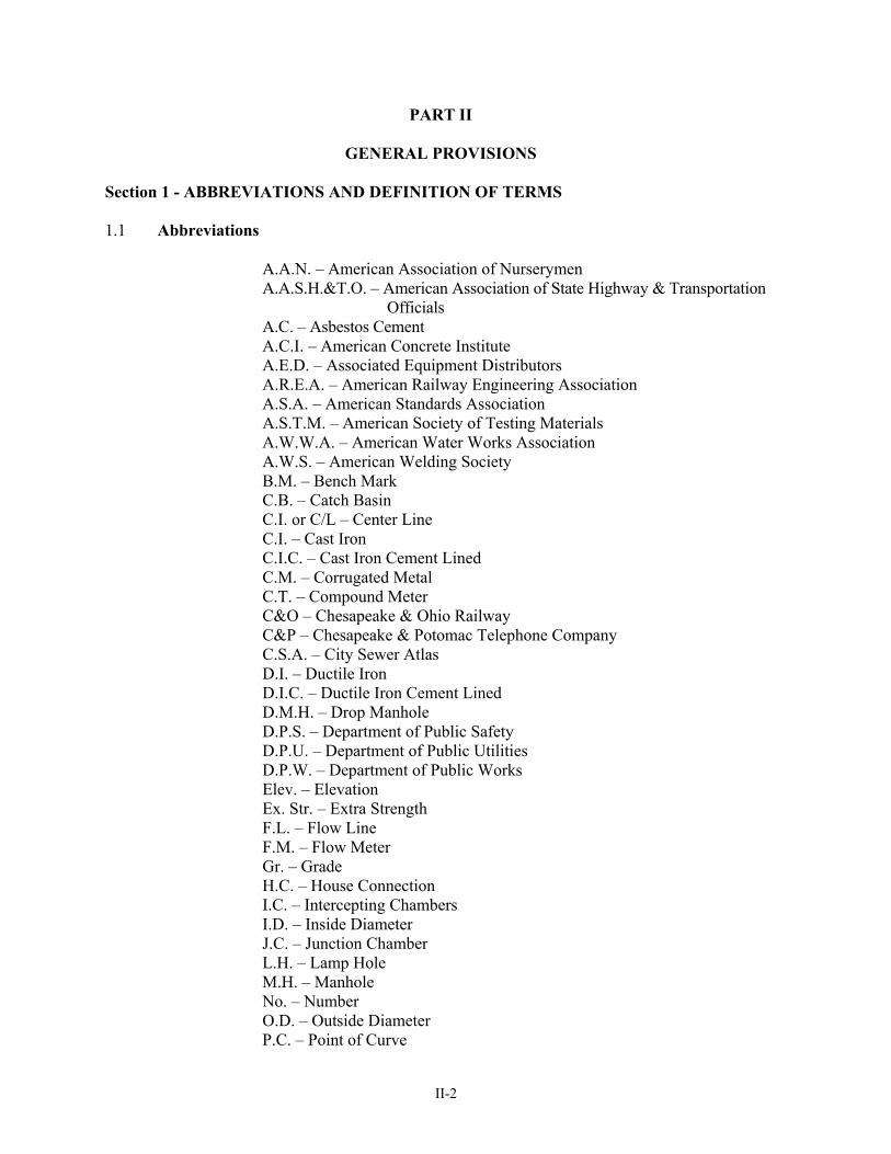
Section 1 - ABBREVIATIONS AND DEFINITION OF TERMS 1.1 Abbreviations
A.A.N. – American Association of Nurserymen A.A.S.H.&T.O. – American Association of State Highway & Transportation
Officials A.C. – Asbestos Cement A.C.I. – American Concrete Institute A.E.D. – Associated Equipment Distributors A.R.E.A. – American Railway Engineering Association A.S.A. – American Standards Association A.S.T.M. – American Society of Testing Materials A.W.W.A. – American Water Works Association A.W.S. – American Welding Society B.M. – Bench Mark C.B. – Catch Basin C.I. or C/L – Center Line C.I. – Cast Iron C.I.C. – Cast Iron Cement Lined C.M. – Corrugated Metal C.T. – Compound Meter C&O – Chesapeake & Ohio Railway C&P – Chesapeake & Potomac Telephone Company C.S.A. – City Sewer Atlas D.I. – Ductile Iron D.I.C. – Ductile Iron Cement Lined D.M.H. – Drop Manhole D.P.S. – Department of Public Safety D.P.U. – Department of Public Utilities D.P.W. – Department of Public Works Elev. – Elevation Ex. Str. – Extra Strength F.L. – Flow Line F.M. – Flow Meter Gr. – Grade H.C. – House Connection I.C. – Intercepting Chambers I.D. – Inside Diameter J.C. – Junction Chamber L.H. – Lamp Hole M.H. – Manhole No. – Number O.D. – Outside Diameter P.C. – Point of Curve
II-3
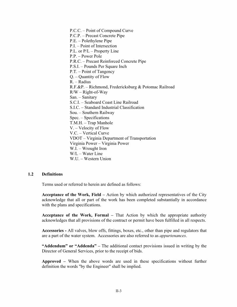
P.C.C. – Point of Compound Curve P.C.P. – Precast Concrete Pipe P.E. – Polethylene Pipe P.I. – Point of Intersection P.L. or P/L – Property Line P.P. – Power Pole P.R.C. – Precast Reinforced Concrete Pipe P.S.I. – Pounds Per Square Inch P.T. – Point of Tangency Q. – Quantity of Flow R. – Radius R.F.&P. – Richmond, Fredericksburg & Potomac Railroad R/W – Right-of-Way San. – Sanitary S.C.I. – Seaboard Coast Line Railroad S.I.C. – Standard Industrial Classification Sou. – Southern Railway Spec. – Specifications T.M.H. – Trap Manhole V. – Velocity of Flow V.C. – Vertical Curve VDOT – Virginia Department of Transportation Virginia Power – Virginia Power W.I. – Wrought Iron W/L – Water Line
W.U. – Western Union
1.2 Definitions
Terms used or referred to herein are defined as follows:
Acceptance of the Work, Field – Action by which authorized representatives of the City acknowledge that all or part of the work has been completed substantially in accordance with the plans and specifications. Acceptance of the Work, Formal – That Action by which the appropriate authority acknowledges that all provisions of the contract or permit have been fulfilled in all respects. Accessories - All valves, blow offs, fittings, boxes, etc., other than pipe and regulators that are a part of the water system. Accessories are also referred to as appurtenances. “Addendum” or “Addenda” – The additional contact provisions issued in writing by the Director of General Services, prior to the receipt of bids. Approved – When the above words are used in these specifications without further definition the words "by the Engineer" shall be implied.
II-4
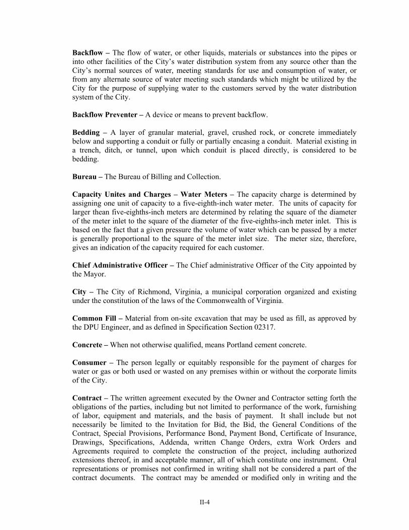
Backflow – The flow of water, or other liquids, materials or substances into the pipes or into other facilities of the City’s water distribution system from any source other than the City’s normal sources of water, meeting standards for use and consumption of water, or from any alternate source of water meeting such standards which might be utilized by the City for the purpose of supplying water to the customers served by the water distribution system of the City. Backflow Preventer – A device or means to prevent backflow. Bedding – A layer of granular material, gravel, crushed rock, or concrete immediately below and supporting a conduit or fully or partially encasing a conduit. Material existing in a trench, ditch, or tunnel, upon which conduit is placed directly, is considered to be bedding. Bureau – The Bureau of Billing and Collection. Capacity Unites and Charges – Water Meters – The capacity charge is determined by assigning one unit of capacity to a five-eighth-inch water meter. The units of capacity for larger thean five-eighths-inch meters are determined by relating the square of the diameter of the meter inlet to the square of the diameter of the five-eighths-inch meter inlet. This is based on the fact that a given pressure the volume of water which can be passed by a meter is generally proportional to the square of the meter inlet size. The meter size, therefore, gives an indication of the capacity required for each customer. Chief Administrative Officer – The Chief administrative Officer of the City appointed by the Mayor. City – The City of Richmond, Virginia, a municipal corporation organized and existing under the constitution of the laws of the Commonwealth of Virginia. Common Fill – Material from on-site excavation that may be used as fill, as approved by the DPU Engineer, and as defined in Specification Section 02317. Concrete – When not otherwise qualified, means Portland cement concrete. Consumer – The person legally or equitably responsible for the payment of charges for water or gas or both used or wasted on any premises within or without the corporate limits of the City. Contract – The written agreement executed by the Owner and Contractor setting forth the obligations of the parties, including but not limited to performance of the work, furnishing of labor, equipment and materials, and the basis of payment. It shall include but not necessarily be limited to the Invitation for Bid, the Bid, the General Conditions of the Contract, Special Provisions, Performance Bond, Payment Bond, Certificate of Insurance, Drawings, Specifications, Addenda, written Change Orders, extra Work Orders and Agreements required to complete the construction of the project, including authorized extensions thereof, in and acceptable manner, all of which constitute one instrument. Oral representations or promises not confirmed in writing shall not be considered a part of the contract documents. The contract may be amended or modified only in writing and the
II-5
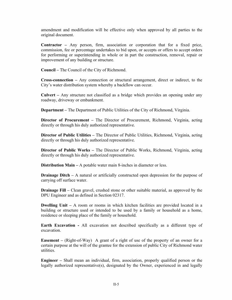
amendment and modification will be effective only when approved by all parties to the original document. Contractor – Any person, firm, association or corporation that for a fixed price, commission, fee or percentage undertakes to bid upon, or accepts or offers to accept orders for performing or superintending in whole or in part the construction, removal, repair or improvement of any building or structure. Council – The Council of the City of Richmond. Cross-connection – Any connection or structural arrangement, direct or indirect, to the City’s water distribution system whereby a backflow can occur. Culvert – Any structure not classified as a bridge which provides an opening under any roadway, driveway or embankment. Department – The Department of Public Utilities of the City of Richmond, Virginia. Director of Procurement – The Director of Procurement, Richmond, Virginia, acting directly or through his duly authorized representative. Director of Public Utilities – The Director of Public Utilities, Richmond, Virginia, acting directly or through his duly authorized representative. Director of Public Works – The Director of Public Works, Richmond, Virginia, acting directly or through his duly authorized representative. Distribution Main – A potable water main 8-inches in diameter or less. Drainage Ditch – A natural or artificially constructed open depression for the purpose of carrying off surface water. Drainage Fill – Clean gravel, crushed stone or other suitable material, as approved by the DPU Engineer and as defined in Section 02317. Dwelling Unit – A room or rooms in which kitchen facilities are provided located in a building or structure used or intended to be used by a family or household as a home, residence or sleeping place of the family or household. Earth Excavation - All excavation not described specifically as a different type of excavation. Easement – (Right-of-Way) A grant of a right of use of the property of an owner for a certain purpose at the will of the grantee for the extension of public City of Richmond water utilities. Engineer – Shall mean an individual, firm, association, properly qualified person or the legally authorized representative(s), designated by the Owner, experienced in and legally
II-6
qualified to practice the profession involved. The term shall apply to the Owner when the Owner is acting as its own Architect or Engineer. Equipment -- Any mechanical or electrical device such as a valve, pump, motor, etc., that is specified and/or used in the construction project. Extension – A new water main from a point beginning at an existing water main. Extra Work – The Contractor shall perform, at the request of the Engineer, any related work not covered by plans and specifications or unit prices which may arise during construction, on the basis of a lump sum negotiated between the Contractor and Architect or Engineer and approved by the Owner for said extra work, which sum shall be broken down into its component parts; or compensation for actual labor, materials and equipment rental involved in said work plus an agreed to percentage of the percentage stipulated in the Bid; or in accordance with the Contingent Items schedule included in the Bid for Water Utility Projects. All changes in the work or extra work made pursuant to a written order or approval shall be performed under the terms of the Contract Document. Whenever changes, alterations, additions, omissions or revisions are called for by the Owner through the Engineer for which the necessary drawings and details have been completed and submitted to the Contractor, or when changes, alteration, additions or omissions are clearly given in writing to the Contractor, he is to submit the proper extra or credit as the case may be, and in addition, and itemized statement of quantities and prices incidental to such revisions, changes, additions and omissions to facilitate the checking of the quantities involved. Guarantee Period – One (1) year following the date of final acceptance of the work by the City unless otherwise specified. Hand Excavation – Excavation that is made with hand tools rather than by excavation machines. Inspector – The person appointed by the Director of Public Utilities, or his duly authorized representative, whose duty it is to inspect the materials used, and see that the work is performed in accordance with the Contract documents; and carry out such instructions as given him by the Engineer. Invert – The lowest point in the internal cross-section of a pipe. Main – The main shall mean the pipe in a street extended for distribution or transmission of public potable water Main Trench – A trench generally parallel to the property lines in which the proposed water mains are to be installed. This also includes excavation for TIE-INS. Mechanical Joint Pipe – Cast or ductile iron pipe and accessories of which the joints are made by a gasket pressed into a bell by a follower ring and bolts.

II-7
Notice to Proceed – A written notice to the Contractor of the date on which he shall begin the persecution of the work. Occupant – A person who is in control of or is in actual possession of or actually occupies a dwelling unit. OSHA – Occupational Safety and Health Administration, www.osha.gov Owner – City of Richmond, Virginia, Department of Public Utilities, as represented by its authorized representative. Paving – The surface of a street or the treatment thereof. Performance Bond – The approved form of security furnished by the Contractor and his Surety as a guaranty of good faith on the part of the Contractor to execute the work in accordance with the terms of the Contract. Person – Every individual, firm, association, partnership or corporation. pH – The logarithm of the reciprocal of the weight of hydrogen ions in grams per liter of solution. Plans – Those drawings specifically referred to as such in the Invitation for Bid or in any Addendum. Drawings issued after the execution of the Contract to further explain, or to illustrate, or to show changes in the work will be known as “Supplementary Drawings” and shall be binding upon the Contractor with the same force as the Plans. Premises – Land, building or other structure and appurtenances thereto. Private Fire Protection System – Water mains, pipes, hydrants, sprinklers and other facilities on private premises within or without the corporate limits of the City. Product – Any material such as pipe, concrete, topsoil, etc., that is specified and/or used in the construction project. Proposal – The offer of the Bidder when submitted on proposal form, properly signed and guaranteed. Public Fire Protection System – Water mains, pipe, hydrants and other facilities in a street used in whole or in part for the protection of premises from fire. Push-on Joint Pipe – Pipe and accessories of which the joints are made by drawing the joint together by technical means, thus compressing a rubber ring into a suitable groove. Restrained Joint Pipe – Pipe and accessories of which the joints are made to prevent joint separation when the pipe is subjected to internal or external forces. Roadway – That portion of the street intended for use of vehicular traffic.

II-8
Rock Excavation – The excavation of solid rock, any single stone or concrete mass having a volume of two cubic feet or more. Select Backfill Material – Any backfill material, other than that excavated material, that is ordered placed in the excavated area by the Engineer. Select Fill – Gravel, crushed stone, limestone screenings or similar material, as approved by the DPU Engineer, used in construction and as further defined in Specification Section 02317. Service Connection – Facilities and equipment in a street connected to a main or a dedicated pipe used to supply potable water to a premise. Service Trench – A trench generally perpendicular to the property lines in which the proposed water service connections are to be installed. Special Pipe Bedding – Any backfill material needed to supplement existing sub-standard material which the pipe must rest on to bring the trench to the established grade. Special Provisions – Special directions, provisions or requirements peculiar to the project under consideration and not otherwise detailed or set forth in the specifications. Special provisions shall prevail over specifications or supplemental specifications and plans whenever in conflict therewith. Specifications – Are the documents, which describe the work which cannot be readily indicated on the Drawings and which set forth the types and qualities of materials and equipment, the methods of installation of such materials and equipment, and the results to be achieved. Street – The whole right-of-way included between property lines, reserved for the accommodation of the traveling public, and its associated structures and slopes, and all ditches, channels, waterways, etc., necessary to its correct drainage Stub-Out – A short extension of a water main including all appurtenances, as approved by the DPU Engineer, and intended to allow a later extension of the water main. Subcontractor – A person, partnership or corporation to whom the Contractor, with written consent of the Owner, sublets part of the work. A Subcontractor has no contractual relationship with the Owner. Superintendent – The executive representative of the Contractor authorized to receive and fulfill instructions from the Engineer and supervise and direct the construction. Test Hole Excavation – Excavation made at the direction of the Engineer to determine the location of existing underground structures or for any other purpose related to the work. Tie-in – Connection of new water facilities to existing water facilities.

II-9
Transmission Main – A potable water main 16-inches in diameter or larger. Warranty – A written guarantee of the quality of a product or equipment including a guarantee of repair or replacement in the case of failure of the product or equipment within a specific time period. Water Service – Meter, facilities and equipment required to furnish service from the main to the property line and the billing for services supplied through the same to the consumer. Water Service Connection – Facilities and equipment in the street area between the main and the property line used to supply water to any premises. Welded Pipe – Coated and lined steel pipe and accessories of which the pipe ends are welded together. Work – That which is proposed to be constructed or done under the contract documents.
II-10
Section 2 - GENERAL CONDITIONS 2.1 General Conditions
The latest issue of the City of Richmond “General Conditions of the Contract” and all amendments thereto are made a part of these Water Specifications by reference.
2.2 Virginia Department of Health Waterworks Regulations, AWWA Standards
A. All designs shall conform to the latest revisions of the Virginia Department of
Health Regulations and the latest revisions of appropriate AWWA standards. B. All designs shall conform to the latest revisions of the Virginia Department of
Health Regulations and appropriate AWWA standards concerning cross-connection control.
III-1
PART III. WATER DISTRIBUTION SYSTEM DESIGN STANDARDS & PROCEDURES

III-2
PART III
WATER DISTRIBUTION DESIGN STANDARDS AND PROCEEDURES
Section 1 - GENERAL DESIGN STANDARDS 1.1 General Requirements 1.1.01 General
A. The design of all utility systems and extensions or modifications thereto shall be performed under the direction of a registered professional engineer with a current registration in the Commonwealth of Virginia in accordance with Title 54.1, Chapter 3 of the Code of Virginia, 1950, as amended. Where applicable, design may be performed under the direction of a certified land surveyor in accordance with Sec. 54.1-408 of the above cited code.
B. All design shall conform to the latest revision of the Virginia Department of Health
Waterworks Regulations.
C. All design shall conform to the requirements of the City’s Department of Public Utilities (DPU). Where the requirements of the State and City are in conflict, the more restrictive requirements shall govern.
D. The designer shall be responsible for obtaining the review and necessary approvals
of all drawings and specifications by applicable City, State, and Federal agencies having jurisdiction. Copies of such approvals shall be submitted to the DPU at the time of final review by the DPU.
E. The developer is required to design and construct his system, properly sized and at
an appropriate location, to permit future extensions to be made at the limits of the subdivision or development in question.
1.1.02 Department of Public Utilities (DPU) Review
A. An Engineering Report shall be submitted to and approved by the Department before approval of drawings and specifications. The Engineering Report shall include domestic, fire, irrigation, commercial, industrial and any other water requirements for the project. The report shall contain an Overall (System Layout) Plan, which shall incorporate all of the proposed construction together with a sufficient amount of the surrounding area in order to clearly outline the interrelationship of the two. The Report shall demonstrate that the water lines are designed to serve the entire service area. Existing and proposed development shall be shown, as well as existing and proposed utilities. Where phase development is contemplated, the extent of each phase shall be clearly delineated. Additional requirements for the Engineering Report are as described in other divisions of these standards and as required by the City.

III-3
B. Prior to construction of water distribution facilities, construction drawings for the
proposed facilities must be submitted for review to the Department of Public Utilities, Technical Services Division. The construction drawings must be in a form acceptable to the Department and shall be submitted in three copies. Prior to submittal of any development/subdivision construction plans, the developer, or its agent, shall submit an overall plan of the proposed water distribution facilities for the entire development. Plans shall be submitted for review and approval to the Department of Public Utilities, Technical Services Division.
C. The System Layout Plan shall be prepared which delineates pressure zone
boundaries for water projects. The map shall clearly define the areas pertinent to interim and ultimate development of the area proposed to be served. The System Layout Plan shall show present and future development and proposed interim and future utilities, as well as those existing utilities that will be affected by or have an effect on the proposed utilities. This necessitates consideration of property beyond the development or subdivision in question. Existing and proposed ground elevations shall be shown at contour intervals not exceeding 2 feet unless otherwise approved. Proposed utilities necessary to serve adjacent properties and associated easements shall be shown.
D. Easements:
1. Off-site easements shall be recorded and the Deed Book and Page Numbers
of the recordation included on the utilities plans before approval of the plans for construction.
2. On-site easement plats shall be submitted to the Department of Public
Utilities, Technical Services Division with the Engineer’s certification that the plats conform to the approved plans and any approved revisions. Any revisions to the approved plans shall be accompanied by the necessary revisions to the easement plats and the Engineer’s certification that the revised plats conform to the plan revisions.
3. Where easements are required on property owned by the City of Richmond
plans shall be submitted for preliminary review. After the DPU agrees to the proposed alignment, the Engineer shall submit plans and easement plats to the City Department (Agency) controlling the property. When the Agency recommends approval of the installation, the Engineer shall forward the recommendation and plats to DPU and the City Real Estate Services. The Real Estate Services will prepare a license agreement for approval by the Chief Administrative Officer. Utility Plans will be approved after the Chief Administrative Officer grants permission to install the utility lines.
4. Installation of trees, structures, buildings, stormwater BMP’s, wetlands,
berms or other obstruction which prevents the proper installation, maintenance, rehabilitation, operation, inspection or removal of water facilities shall not be allowed within any permanent water easement unless approved by the Director.
III-4
1.1.03 System Design
A. An analysis shall be prepared that tabulates the number of people being served or proposed to be served as determined from existing zoning. The tabulation shall be by incremental areas for evaluation purposes. Itemize all other water requirements being served or proposed to be served including fire, irrigation, commercial, industrial and any other water requirements.
B. Average, maximum day, maximum hour, and fire flows shall be developed for areas
and sub-areas and tabulated in the report as deemed necessary or appropriate.
C. The design documentation shall address total current and projected future flows and system capacities of existing and proposed utilities and shall provide the proposed water main sizes.
D. The design shall be based on ultimate development (complete build-out of the area)
and shall present such factors as deemed necessary for a sound evaluation of the several factors used in development of the report.
E. Where an alternate design is proposed that would incorporate interim or staged
construction, the report shall develop the alternate design and shall present a thorough investigation and justification for consideration of the alternate.
1.1.04 Miscellaneous Design Information
A. Request for temporary water service for construction trailers shall be directed to the DPU New Services Office, 400 Jefferson Davis Highway, 23224. Phone (804) 646-8543.
B. All existing water services to the property shall be shown on the utility plan. If the
existing water services will not be utilized, they shall be abandoned in accordance with specification Section 02220.
C. Portable meters are available for construction purposes.
1.1.05 Separation of Water Lines and Sanitary and/or Combined Sewer Lines
A. Follow Virginia Department of Health, Waterworks Regulations for separation of water mains and sewer lines.
B. During the course of construction, the Contractor shall take proper steps to protect
water supply facilities within the construction limits from contamination by sewage.
C. The following criteria is applicable when water facilities are installed in the proximity of sewer lines:
1. Parallel installation: Under normal conditions, water mains shall be laid at
least 10 feet horizontally from a sewer or sewer manhole. The distance

III-5
shall be measured edge-to-edge. Under unusual conditions when local conditions prevent a horizontal separation of 10 feet, the water main may be laid closer to a sewer or sewer manhole provided that:
a. The bottom (invert) of the water main shall be at least 18 inches
above the top (crown) of the sewer; b. Where this vertical separation cannot be obtained, the sewer shall be
constructed of AWWA approved water pipe, pressure tested in place without leakage prior to backfill; and
c. The sewer manhole shall be of watertight construction and tested in
place.
2. Crossing: Under normal conditions water lines crossing sewers shall be laid to provide a separation of at least 18 inches between the bottom of the water line and the top of the sewer whenever possible. Under unusual conditions when local conditions prevent a vertical separation described above, the following construction shall be used: a. Sewers passing over or under water mains shall be constructed of the
materials described in the “parallel installation” section; and b. Water lines passing under sewers shall, in addition, be protected by
providing:
i. A vertical separation of at least 18 inches between the bottom of the sewer and the top of the water line;
ii. Adequate structural support for the sewers to prevent excessive deflection of the joints and the settling on and breaking of the waterline; and
iii. That the length of the water line be centered at the point of the crossing so that joints shall be equidistant and as far as possible from the sewer.
3. No water pipes shall pass through or come in contact with any part of a
sewer manhole. 1.1.06 Water Lines Crossing Railroads and Roadways
A. Water Lines Crossing Railroads and Roadways:
All water line crossings of railroads, roadways, and other major structures shall be encased in a casing pipe. Design of railroad crossings shall comply with the requirements of American Railway Engineering Association Specifications, Part 5 – Pipelines (latest revisions).
III-6
1.1.07 Protection of Water Supplies
A. There shall be no physical connection between a potable water supply and a sewer, sewage pumping station, or appurtenances thereto.
1.1.08 Backfill and Compaction
A. The Design Engineer shall include compaction requirements on the plans:
1. Minimum compaction shall be specified. 2. Compaction requirements for roads and paved areas shall be specified. 3. Compaction requirements adjacent to structures shall be specified.
B. Additional backfill and compaction requirements are provided in specification
Section 02317. 1.1.09 Contacting Property Owners: Prior to performing any survey and design work on private
property, the engineer/surveyor shall notify all landowners that may be affected by the design or installation of the proposed utility line. Notification shall be made in the form of a letter to be sent to the property owner seven to ten days before commencing work. Copies of such letters shall be provided to the Utilities Department along with the initial plan submittal.
1.1.10 Backflow Prevention
A. All pipeline, meter, irrigation, fire systems, and plumbing work shall be in accordance
with the latest City of Richmond Backflow Prevention Regulations and Virginia Department of Health Regulations.
B. Installation of all backflow devices shall be performed by a licensed plumber in
accordance with the Commonwealth of Virginia Department of Professional and Occupational Regulations or hold a current NICET Level III Certificate.
III-7
1.2 Drawing Organization And Format 1.2.01 Drawing Organization
A. Drawings shall consist of the following types of sheets arranged in the order listed:
1. Cover Sheet 2. Index Sheet (if necessary) 3. Standard General Notes and Notes 4. Plan Sheets 5. Profile Sheets (may be combined with plan sheets) 6. Standard Sheets and Special Details. 7. Erosion and Sediment Control Details/Environmental Site Assessment
B. Projects consisting of only structures may not require plan and profile sheets.
1.2.02 Sheet Format
A. All construction drawings shall be on sheets 24 inch x 36 inch.
B. The cover sheet shall contain the Owner's name and project description in large, distinctive letters, a vicinity map drawn on a scale of 1 inch = 2,000 feet to indicate the general vicinity of the contemplated construction, an index to the plan sheets and a signed stamp of the design engineer or person responsible for the design. The vicinity map shall include a North arrow and a scale.
C. A plan shall be prepared for water main projects. The index map shall be to a scale
not less than 1 inch = 600 feet and shall show all proposed utilities with tie to existing utilities. The lines of the proposed construction, together with proposed utility structures, shall be indexed to the drawings to indicate the extent of coverage on each drawing or, in the case of structures, to the group of drawings involved.
D. Plan sheets, as well as Plan and Profile Sheets, shall show horizontal, vertical, and
topographical data as outlined in Section 1.2 of these Standards.
E. All plans shall bear a suitable title showing the name of the municipality, sewer district, and institution or other Owner(s). The plans shall also show the scale in feet, the North arrow, the date, and the name of the licensed professional responsible for preparation of the plans. Also, each plan sheet shall bear the same general title identifying the overall project, and shall be numbered.
F. Drafting Conventions:
1. Standard Symbols subject to approval by the Department are to be used for
drawings. When Standard Symbols are not used, a Symbol Key shall be included on the Cover Sheet. Existing facilities shall be half tone.
III-8
2. Standard Symbols – Proposed Facilities: Symbols shall be as shown above except that solid lines shall be used to for pipes, line weight shall be no lighter than 0.024 inches and no heavier than 0.031 inches.
3. Text, Dimensions, and Notes: Lettering shall be consistent and clear with a
minimum height of 0.125 inches (1/8 inch). The larger size lettering shall have proportionately wider line widths. When drawings are prepared using computer aided drafting (CAD), the minimum text height shall be 0.10 inches.
G. Drawing Standards:
1. All plans submitted for review shall comply with the format and quality
control requirements of the DPU Standards. Plans which do not meet these criteria will not be accepted for review.
2. Plans submitted for review shall be direct blueline or blackline prints.
Photocopies or telefacsimile reproductions will only be accepted for information or preliminary review purposes.
3. Drawings must be clear and legible. Text shall be opened so that it is
readable when drawings are reduced to half size. All drawings must be capable of producing legible second generation prints after being reduced to half size.
4. The contrast of the printed material shall be high, with blank areas being as
white as possible, and all information being as dark as practicable, while remaining clear and distinct.
5. Shading, such as on plan views for paving, shall not be used on the
drawings where it will hide any information when the drawing is photocopied or scanned. Shading with a pencil or using dark film will not be acceptable. For areas that need to be identified or highlighted, stippling or cross hatching may be used, provided no other information is hidden.
6. It is the intent of these Standards that all submitted plans are scanned for
archiving. If there is any question regarding legibility, the plans shall be scanned and acceptability determined by the City upon printing of the scanned image at half size.
H. Additional Information:
1. Drawings shall include estimated materials quantities. 2. Horizontal scale in Plan and Profile Sheets shall be no smaller than 1 inch
= 50 feet. 3. A bar scale shall be included on each sheet.

III-9
4. Vertical profile scale shall be no smaller than 1 inch = 10 feet. 5. All known existing structures and utilities, both above and below ground,
which might interfere with the proposed construction, particularly water mains, sewer mains, gas mains, storm drains, utility service lines, etc. shall be shown in plan and profile.
6. Benchmarks shall be set no more than 500 feet apart along the lines of
construction but outside the limits of construction. Datum for elevations shown shall be USGS (United States Geographic System) Mean Sea Level or City Datum. The plans shall identify the datum used.
7. Drawings shall show off-site easements required and identify Deed Book
and Page Number. 8. Drawings shall refer to the applicable DPU water and sewer sheet numbers
for the project location.
1.3 Easement Requirements 1.3.01 Easement surveys shall be made and easement plat prepared in all cases where proposed
construction limits exceed the limits of public rights-of-way. These surveys shall tie the lines of proposed construction to existing property lines and property corners, where the property may be identified by corners. Where readily identifiable corners are not found, fence lines and corners and other indications of property lines may be used. In the absence of any such identifications, the surveyor shall exert maximum effort to tie the survey to boundaries as set forth on existing plats and in descriptions.
1.3.02 Temporary construction easements shall be a minimum of 30-feet wide, not including the
permanent easement. 1.3.03 Permanent easements shall be a minimum of 20 feet in width with consideration for wider
easements where more than one facility may occupy an easement, or where, because of line size or access requirements, wider easements are desirable. Where lines have cover in excess of 10 feet, the minimum easement width shall be increased to a minimum of 30 feet in width. Buildings or other structures, and trees shall not be placed in easements.
1.3.04 Construction easements shall be acquired for all public water facilities where work will be
performed on private property. Developers constructing facilities are not required to have construction easements where work is on the developer’s property. Construction easements shall provide a minimum working width of 50 feet, including the 20 foot permanent easement, unless otherwise approved. Generally it is desirable to provide more construction easement on one side than on the other. This allows room for construction traffic and material storage.
1.3.05 The standard size of easement plats shall be on sheets 8-1/2 inch x 11 inch. Where longer
easements are required, multiple sheets may be utilized.

III-10
Easement plats of different sizes may be used if the overall size of the sheet does not exceed 18 inches x 24 inches and meets all requirements of the City Real Estate Services. The easement centerline shall be shown together with the limits of both the proposed permanent and construction easement widths referenced to the centerline of the easement. Bearings and distances shall be shown on the centerline of the easement and on the right-of-way or property lines where they intersect the centerline. Distances shall be shown from fixed points on both the centerline and the property lines to the intersection of the two. Bearings, distances, and closures shall be to the degree of accuracy of 1 in 8,000 except that approximations will be permitted where it is considered impractical to delineate existing property lines. The body of the plat shall show the name of the property owner and the Deed of Will Book reference for the source of title. The names of all adjacent property owners and a north arrow shall also be shown. Street names or highway route numbers shall also be shown where applicable.
Section 2 - DESIGN STANDARDS FOR WATER DISTRIBUTION FACILITIES 2.1 General Requirements 2.1.01 Water and fire protection distribution facilities are to be provided solely for the purpose of
supplying potable water and fire protection. Under no circumstances shall cross-connections be allowed to unapproved water facilities. All plans must comply with the Department's Cross Connection Control Program. The following design parameters should be used in the design of water distribution facilities. Water transmission facility design parameters may change and are superceded by project specifications on a case by case basis.
2.2 Technical Design 2.2.01 System Layout.
A. The overall layout and general design shall conform to the parameters set forth in the approved Engineering Report. In general, main line valves are required at intervals of 1000 feet and at tees and crosses to allow adequate control of the system without major system shutdowns.
B. All water mains shall be located, where practical, in:
1. Legally established road rights-of-way. 2. Legally established permanent easements for such purpose which are
immediately adjacent to legally established road rights-of-way or paved areas either existing or as proposed by the designer.
3. Paved areas, or as directed by the City’s Engineer.
III-11
C. Construction shall generally be parallel to the center line of roads or easements. The same offset shall be used throughout except when existing utilities dictate a change in offset along the proposed line.
D. Water mains shall be installed a minimum of 10 feet from any part of any structure,
building, or its foundation and a minimum of 5 feet from curbs, curb gutter pans, sidewalks, and similar structures. This distance is designed to allow for maintenance access without damaging the structure.
2.2.02 System Design.
A. The proposed facilities together with the pertinent existing facilities shall be evaluated based on the hydraulic design, demand design, and fire protection design requirements contained herein.
B. The Designer shall submit to the DPU a neat and orderly set of design calculations
to illustrate maximum demands and fire flows, pipe size selection, and fire protection requirements. Where system flow information is needed, the Designer shall contact the Richmond Fire Department for fire flow pressure testing through fire hydrants.
C. Non-ferrous (2” polyethylene) pipes shall have a detectable tracer buried in the
trench 18 inches above the main but no less than 24 inches below grade. If the pipe is installed with trenchless technology, the tracer wire may be attached to the pipe.
D. Dead end lines shall be minimized by looping mains where practical and where
approved by DPU. If looping is impractical, use hydrant flushing assembly pipe for runs less than 300’ at the end of mains.
E. The Designer shall refer to the Virginia Department of Health Waterworks
Regulations and the DPU Cross-Connection Control Backflow Prevention Program.
F. Domestic meter calculations shall be shown on the plans.
G. Fire protection flow requirements shall be shown on the plans. 2.2.03 Hydraulic Design.
A. Hydraulic design shall be accomplished by use of a hydraulic model acceptable to the DPU. A Hazen-Williams coefficient of friction equal to 120 shall be used for purposes of design for new pipelines. Coefficients of friction for existing pipelines shall be determined by fire flow tests conducted by the developer unless the DPU has data to indicate the coefficient that should be used for existing lines. The City has numerous water mains with C valves significantly less than 120 due to the age and material types.

III-12
2.2.04 Demand Design. A. Maximum rates of water consumption shall be calculated and used as a basis of
hydraulic design. Average daily water consumption rate values for the number and type of consumers anticipated to be served shall be based on those contained in the Virginia Department of Health Waterworks Regulations. The minimum allowable service pressure during maximum hourly demands shall be 35 psi. Any such rates not given or any deviations from tabulated rates shall be estimated and justified by the Designer and approved by the DPU. The average annual daily water consumption rates shall be adjusted by a multiplier to arrive at the maximum daily and maximum hourly water consumption rates expressed as follows:
Qmd.= Qa x Cmd Qmh.= Qa x Cmh
Qmd is maximum daily water consumption rate. Qmh is maximum hourly water consumption rate.
Qa is average annual daily water consumption rate. Cmd is constant varying from 1.5 to 1.75. Cmh is constant varying from 2.5 to 2.75. Qmh shall be used as the basis for hydraulic design.
2.2.05 Fire Protection Design.
A. Rates of flow for fire protection shall be estimated based on the 1980 ISO Fire Suppression Rating Schedule, or latest edition, Section 1, Public Fire Suppression, Subsection 300, Needed Fire Flow, including Definitions Extracted From The Code of Federal Regulations and including Occupancy Classifications, Non-Manufacturing and Occupancy Classifications Manufacturing and Special Hazards. A maximum allowance of 50% reduction in needed fire flow may be allowed for buildings with automatic sprinkler systems that provide full protection.
B. The minimum fire flow from any individual fire hydrant shall be 750 gpm. The
minimum flowing pressure at maximum flow shall be 20 psi.
C. During maximum rated fire flow conditions, the pressure drop in any fire protection system shall not exceed 15 psi from the point of connection at the existing City system to any fire hydrant or any combination of required hydrants.
D. The minimum size water line used for fire protection to properties zoned
agricultural or single family residential shall be 6 inches in size. The minimum size water line used for fire protection to properties zoned multi-family residential, commercial, or industrial shall be 8 inches in size.
E. The minimum sized fire service lines above shall be looped to provide feed from at
least two directions where practical. The sizing of minimum-sized fire service lines and larger than minimum-sized fire service lines shall be determined by Sections

III-13
2.2.03 and 2.2.05 "Hydraulic Design" and "Fire Protection." Not more than one fire hydrant shall be installed on a 6-inch dead end line.
F. Dead end lines shall not contain more than 600 feet of the minimum sized line.
Additional lengths required shall be provided by increasing the line size.
G. The Richmond Fire Department shall recommend location and placement of new fire hydrants.
H. Private hydrants shall be governed by Section 12-47 of the Richmond City Code
and shall meet the regulations of the Richmond Fire Department.
I. Public fire hydrants should be located at intersections wherever possible. The location should be selected to be (1) on the same side of the street as the main, (2) as safe from traffic as possible, and (3) a minimum disruption to parking. Mid block hydrants should be at property lines wherever possible. Where curbs and gutters do not exist, hydrants must be 8’ to 12’ from solid roadway. On curbed and guttered streets, hydrants should be 1’-6” from the back of the curb. Outlet centers must be approximately 30” above the ground or sidewalk level. Breakaway couplings shall be a minimum of 2” above grade and not more than 6” above grade.
J. Fire hydrant spacing for properties zoned agricultural or single family residential
with spaces between houses greater than 100 feet shall not exceed 1000 feet or require a hose lay of over 400 feet from the hydrant to any part of any structure to be protected.
K. The following table is a list of fire flow requirements for residential areas consisting
of one family and small two family dwellings not more than two stories high:
Exposure Distance Required Fire Between Dwellings Flows (gpm) > 100’ 500 30 - 100’ 750 – 100 <30 1500 - 200
L. Fire hydrant spacing for properties zoned multi-family residential, commercial, or
industrial shall not exceed 500 feet or require a hose lay of over 350 feet from the hydrant to any part of any structure to be protected. Where multiple fire hydrants are needed to supply the required fire flow, all necessary hydrants must be located within the specified hose lay.
M. No fire hydrant shall be placed closer than 50 feet from the face or overhang of any
building to be protected.
N. The above criteria for spacing fire hydrants may be modified by the DPU to improve fire hydrant accessibility for fire fighting purposes.

III-14
O. Structures on private property protected by an automatic sprinkler system and/or private fire hydrants and directly connected to the City's water system require installation of a metered service fire line.
P. Fire flow requirements for land use characteristics are summarized in the attached
table.
Q. For additional information, refer to Specification Section 02514.
R. Public Fire hydrants shall be located, where practical, in legally established road rights-of-way. Easements may be used only if road rights-of-way are impractical to use, or as approved by the City’s Engineer.

III-15
TABLE 2-1
FIRE FLOW CRITERIA FOR WATER SYSTEM EVALUATION
Land Use Characteristics Min.
Fire Flow (gpm)
Fire Duration (hours)
Desired Fire Storage
Volume (mg)
A. Residential
Single Family
Low density
(over 100’ between buildings)
high density
(less than 100’ between buildings)
Multifamily
Townhouse, apartments
500
1500
1500
2
2
2
0.06
0.18
0.18
B. Office/Retail
Low density/strip
Shopping centers
High density office (multistory)
2000
3000
6000
2
3
4
0.24
0.54
1.44
C. Institutional 4000 4 0.96
D. Industrial
Low to medium density, low to Normal combustibility contents
High density, or higher Combustibility contents
4000
8000
4
4
0.96
1.92
III-16
2.2.06 Structural Design of Pipe Systems.
A. Structural requirements must be considered in the design of all water mains and appurtenances. Water mains shall be designed in accordance with Specification Sections 02500 and 02505.
B. Proper blocking and/or restraints must be provided and shown on the drawings.
Where blocking is not detailed on the drawings, restrained joints shall be used. C Proper support shall be provided for aerial or suspended lines.
D. Any potable water line crossing above surface water must be:
1. Adequately supported. 2. Protected from freeze damage.
3. Accessible for repair or replacement.
4. Above the 100-year flood plain elevation.
E. Any potable water line crossing under surface water must meet the following
requirements:
1. The pipe shall be of special construction having flexible watertight joints. 2. Gate valves shall be provided at both ends of the water crossing so that the
section can be isolated for test or repair; the valves shall be easily accessible and not subject to flooding.
3. For the purpose of testing the section of line crossing the surface water and
for locating leaks in that section, permanent manual air release valves shall be available at each end of the crossing and at a reasonable distance from each side of the crossing.
F. Steel casing pipe shall be sized in accordance with the Standard Details.
2.2.07 Miscellaneous Considerations.
A. The minimum size water line pipe to be used for normal domestic water supply (not including fire protection) shall be 3 inches and be capable of supplying 15 gpm per residential connection at 35 psi except where fire protection lines are to be provided.
B. Air and air/vacuum release valves and related fittings shall be provided by the
developer. The type, size, etc., shall be specified by the Designer, subject to approval by the DPU.

III-17
C. The minimum depth of cover for water mains shall be 3-1/2 feet from the top of pipe to grade unless approved otherwise by the Engineer. Additional depth shall be provided where required for thrust restraint or to clear underground obstructions.
D. The profile of water services at ditch lines shall be shown on plans and have a
minimum of 24 inch cover at the ditch invert. E. Service lines larger than 1 inch, with meters larger than 5/8 inch, shall be sized in
accordance with AWWA Manual M-22, Sizing, Water Service Lines and Meters or alternative procedure approved by the Department of Public Utilities.
F. Where water lines are subject to extreme variations in temperature (i.e., attached to
bridges or box culverts) consideration shall be given to expansion and contraction of pipe materials and the freezing of the line contents.
G. Cathodic Protection - The Designer shall consider ground conditions in the case of
metallic conduits and provide suitable cathodic protection where necessary. H. Irrigation systems shall use the appropriate backflow devices as indicated in the
DPU’s Cross Connection Control and Backflow Prevention Program. I. Where exposed to traffic, meter boxes and vaults shall be designed for the
appropriate traffic loading (minimum AASHTO H-20 or greater loading if required).
J. Dead ends of all mains shall be provided with either a fire hydrant or a Water Main
Blow Off Assembly, as appropriate, to provide adequate flushing of the main. K. No concrete shall be placed over water mains unless otherwise approved by the
DPU. L. Ductbanks or other utilities shall not be placed over water mains unless otherwise
approved by the DPU. M. Pipe materials shall be in accordance with Section 02505.
2.3 Drawings 2.3.01 In addition to the requirements of Section 1.2. - "Drawings Organization and Format" of
these Standards, the drawings shall incorporate the following features:
A. Drawings for water lines shall show stationing, pipe size and material, northings and eastings, and curve data to adequately define the water line location. Water line dimensions including distances to structures, right-of-way, face of curb, edge of pavement, and property lines shall be shown. Drawings shall show all new and existing utilities, including pipelines, ductbanks, and similar items.
B. The drawings shall also show all fire hydrant and water service connections. Fire
hydrants and all water services shall be shown in plan and profile views which are

III-18
labeled by stations. Water service connection points to existing mains shall be shown, including water line dimensions as called for in Paragraph 2.3.01 A above.
C. Profiles shall be provided for all water lines 3 inches and larger in size. Grades
shall be calculated and shown on the profiles. Profiles shall also show all air, air/vacuum relief valves, fire hydrants, and blow-off locations.
D. Water lines shall be referenced by distances from right-of-way lines, buildings,
other utilities and curbs and gutters and northings and eastings. E. Blocking and/or restraint details. F. Current City of Richmond, Department of Public Utilities Water Notes, Pipe
Material Notes, and Estimated Material Quantities shall be shown on the plans. G. All drawings for water mains crossing sewers, force mains, or other utilities shall
show points where crossings occur. Crossings shall be shown in both Plan and Profile. The Profile shall clearly indicate vertical clearance between utilities.
H. Meter sizing form, backflow prevention details, and ISO calculations shall be
shown on the plans.
I. All fittings, including valves, bends, tees, etc., shall be shown on the plan and profile.
J. Existing utilities shall be shown on site plans.
2.4 Standard Forms The following are standard forms provided for use on City Projects. The following forms are incorporated into the Standards.
- Contractor Release of Asset Requirements (Pages 1-4) - Sample Deed of Easement (DE-1, DE-2) - Sample Contract to Extend Water Mains (WM-1, WM-2) - Review Checklist for Water Plans
Standard Forms are in Appendix B.

IV-1 4
PART IV. ADDITIONAL PROVISIONS

IV-2 4
PART IV
ADDITIONAL PROVISIONS SECTION 1 - ADDITIONAL PROVISIONS 1.1 Special Project Procedures
A. Construction operations in public streets, roads or alleys, shall be confined to as
small a space as is practicable and shall be subject at all times to the approval of the Department of Public Work’s Traffic Engineer. Unless otherwise directed by the Traffic Engineer, the Contractor shall perform the proposed construction as follows:
1. Obtain and apply for all construction permits required. 2. Notify the City Department of Public Utilities and Traffic Engineer not less
than 48 hours before work is to start. A DPU construction inspector must be assigned to the job before work may commence.
3. Contact the Traffic Engineer in regard to the permitted working hours and
the required signing and barricading which shall be used while working in the public right-of-way. Submit approved permit and any modifications to DPU.
4. Proper signs and barricades shall be used at all times. All signs and
barricades shall conform to the standards indicated in the Virginia Department of Transportation’s (VDOT) Work Zone Safety, Guidelines for Temporary Traffic Control. Additional signs, barricades, flaggers and other traffic control devices shall be used on heavily traveled roads when required by the DPU’s Engineer and/or the Traffic Engineer.
5. Not over 500 feet of trench, or as required in the Work in Street Permit,
shall be open at any one time, and not more than one intersection blocked. Not more than 15 feet of trench shall remain open over night and then only when required to expose end of pipe that will be extended the next working day, and it shall be properly barricaded, steel plated, or equipment parked over it, as required by the DPU Engineer.
6. If, in the opinion of the DPU’s Engineer, the material taken from the trench
is not suitable for backfilling, it shall be removed, and an acceptable material used for backfilling trenches.
7. Sprinkled water or other appropriate measures shall be used to settle dust
whenever necessary and required by the DPU Engineer.
8. Stone dust may be required by the DPU Engineer to cover paved surfaces to keep spoils from staining the pavement
IV-3 4
9. All loose material shall be swept from hard surface immediately behind the backfilling.
10. Main line and lateral trenches crossing the pavement at right angles,
trenches running parallel, or nearly so, and lines within a street intersection, shall be backfilled with approved crushed material (VDOT 21A or 21B) and mechanically compacted.
11. VDOT 21A or 21B stone of 6" compacted depth shall be placed on top of
regular compacted trench backfills when any trench dug parallel with pavement which disturbs the road shoulder within 5 feet from the edge of the pavement. Any trench dug parallel with the pavement which disturbs the road shoulder five or more feet from the edge of the pavement may be refilled with the same material when determined to be suitable by the DPU Engineer, that was removed from the trench, and suitable stone will not be required.
12. The Contractor shall warranty and maintain trenches for a period of 12
months from the completion of work. 13. All walks, driveways, lawns, swales, etc. shall be maintained and restored to
their original condition by the applicant and maintained for the 12 month period.
14. All paving, curbs, gutters, and sidewalks made necessary by the
Construction work must be restored and approved by the City Department of Public Works. Granite curbing and cobbles must be taken out and replaced.
15. Approval of the paving does not relieve the Contractor of the responsibility
of damage due to settlement or any type of failure during the 12 month warranty period.
16. In the event that these conditions are not complied with after reasonable
notice has been given, the DPU will correct the defective work at the developer's expense.
B. Construction operations on private property shall be performed as follows:
1. Obtain and apply for all construction permits required, including building
and plumbing permits. 2. Notify the City Department of Public Utilities and City Cross-Connection
Control Specialist not less than 48 hours before work is to start. A DPU construction inspector must be assigned to the job before work may commence.
IV-4 4
1.2 Coordination
A. All phases of the construction which involve the City’s utilities shall be scheduled for consultation with the Owner and the City’s DPU or their representative. Liaison in this matter shall be required before beginning work. The Contractor shall fully pay all required fees. The Contractor shall notify the Gas and Water Distribution Division at 646-8332 not less than 48 hours in advance of commencing work in order that a Construction Inspector may be assigned to the job. The Contractor shall fully pay all required fees and shall give not less than 48 hours notice in advance of the need for making any connections to the existing water system. The City may disapprove the time and date of any and all connections and will advise the Contractor as to a suitable time and date.
B. The Contractor shall not operate any valves in the City system. C. The Contractor shall not tap, cut into, or otherwise disturb any mains in the City
without the written permission of the DPU Engineer. 1.3 Project Meetings
A. A preconstruction conference with the Department of Public Utilities and the Contractor shall be scheduled before beginning any work on the water system.
B. Progress meetings will be held at regular intervals. The time and location shall be
subject to approval of the DPU’s Engineer.
1.4 Submittals
A. Construction Schedules
1. Submit a detailed construction schedule prior to the preconstruction-conference.
2. Submit 3 sets of approved plans and specifications prior to the preconstruction meeting.
3. Submit all shop drawing and material data sheets for approval prior to the start of work.
4. Submit all approved backflow and cross connection control information prior to the preconstruction meeting.
5. Submit payment requests for all water utility work to be performed by the City prior to the preconstruction meeting, including inspections, tie-ins, extensions, and water service, etc.
1.5 Materials and Equipment
A. Quality: Material and equipment incorporated into the work shall be new and unused and:
1. Conform to applicable specifications and standards.

IV-5 4
2. Comply with size, make, type and quality specified or as specifically approved in writing by DPU.
3. Manufactured and fabricated products:
a. Design, fabricate, and assemble in accordance with the best
engineering and shop practices. b. Manufacture like parts of duplicate units to standard size and gages,
to be interchangeable.
c. Two or more items of the same kind shall be identical, by the same manufacturer.
d. Products shall be suitable for service conditions.
e. Equipment capacities, sizes, and dimensions shown or specified shall be adhered to unless variations are specifically approved in writing.
4. Do not use material or equipment for any purpose other than that for which
it is designed or is specified.
5. Except as specifically indicated or specified, materials and equipment removed from the existing structure shall not be used in the completed work.
B. Storage and Protection:
1. Store products in accord with manufacturer's instructions, with seals and
labels intact and legible.
a. Store products subject to damage by the elements in weather tight enclosures.
b. Maintain temperature and humidity within the ranges required by
manufacturer's instructions.
2. Exterior Storage
a. Store fabricated products above the ground on blocking skids; prevent soiling and staining. Cover products which are subject to deterioration with impervious sheet coverings; provide adequate ventilation to avoid condensation.
b. Store loose granular materials in a well-drained area on solid
surfaces to prevent mixing with foreign matter.
3. Arrange storage in a manner to provide easy access for inspection. Make periodic inspections of stored products to assure that products are

IV-6 4
maintained under specified conditions and are free from damage or deterioration.
4. Protection After Installation: Provide substantial coverings as necessary to
protect installed products from damage from traffic and subsequent construction operations. Remove when no longer needed
1.6 Shutdowns and Tie-Ins
A. Connections to Existing Facilities: If any connections, replacement, or other work requiring the shutdown of an existing facility is necessary, schedule such work at times when the impact on the OWNER’s normal operation is minimal. Overtime, night and weekend work may be required to make these connections.
B. Request for Shutdowns: Submit a written request for each shutdown to the DPU at
least 72 hours in advance of any required shutdown. C. All shutdowns to existing plant and pumping facilities shall be kept to an absolute
minimum duration. Shutdowns and tie-ins to existing facilities shall be done in a manner and at a time approved by the Owner. A detailed plan of each shutdown and tie-in (including procedure and time table) shall be submitted for the Owner’s approval. The detailed plan shall be submitted well in advance of the date scheduled for starting such work to allow time for review by the Owner and for making revisions to the plan as may be required.
D. No shutdowns shall be made to any part of the existing plant or pumping facilities
without the permission of the DPU. The DPU shall make all shutdowns.
E. To keep shutdowns to an absolute minimum time:
1. Do all preparatory work possible at each place of work prior to the specified facility being taken out of service.
2. Have adequate personnel and equipment to work simultaneously, if
required, at more than one location of shutdown work.
3. Work continuously more than the regularly scheduled working day or work double shifts, if directed by the DPU Engineer.
4. Perform work at a time of day, night or on weekends when the least water
demand on the plant or pumping facility exists if directed by the OWNER.
5. Use non-shrink grout or high early-strength concrete at those connection points which may require new concrete work to be joined to existing.
F. Provide all temporary connections and/or controls to operate equipment which may
be necessary until final connections and/or controls are complete.

IV-7 4
1.7 Record Drawings
A. At the site keep and maintain one record copy of the approved drawings, reference documents, and all technical documents.
B. Using drafting symbols and standards consistent with the original documents,
annotate approved drawings neatly and clearly in color to show all changes made during the construction period.
C. Store record documents separate from documents used for construction.
D. On Record Drawings, legibly mark each item to record actual construction,
including:
1. Location, size and material for piping, concealed and exposed. 2. Changes in product and equipment dimensions, structural openings,
foundations.
3. Measured locations of internal utilities and appurtenances concealed in construction, referenced to visible and accessible features of the work.
4. Measured horizontal and vertical locations of underground utilities and
appurtenances, referenced to permanent surface improvements as described herein. Measurements shall be made to each valve, valve box, bend, and tee. Measurements to underground pipe shall be made not less frequently than at every 100 foot station. Provide additional measurements as required to locate underground pipe. At least two horizontal measurements shall be made. These measurements shall be made at right angles to rights-of-way line. Where rights-of-way lines are unknown, provide measurements referenced to curb lines, edge of pavement, or, if these items are not practical, referenced to permanent surface improvements, such as manhole covers.
5. Field changes of dimensions and detail.
6. Details not on original drawings.
7. Any other variations between the work actually provided and that shown on
the approved Drawings.
E. Annotated drawings are to be made available to the DPU for reference at all times. F. At completion of the CONTRACT deliver to the DPU Engineer one set of clearly
readable, reproducible utility Contract Drawings reflecting all changes made during construction. Mark each drawing “Record Drawing” in ink.
IV-8 4
1.8 Permits
A. Obtain permits from various City agencies necessary for the work. This will include but not be limited to:
Land Disturbance Permit Work in the Streets Permit Building Permit Electrical Permit Plumbing Permit Mechanical Permit Water Main Extension Contract Water Service Permit Encroachment Permit Easement Agreements Blasting Permit (if blasting is required)
B. Provide a copy of the permit application and approved permit to the City prior to
starting any work that involves land disturbance or work in the street. C. Obtain any other permits required from any Federal, State, or City agencies having
jurisdiction for the work. Comply with all provisions of such permits regarding workmanship, schedules, maintenance of existing operations, notification of starting construction time restrictions upon closing streets, traffic control, and other conditions under which the permit is issued.
D. Obtain and pay for all permits, licenses and other authorizations required from the
prosecution of the work, including the cost of all work performed in compliance with the terms and conditions of such permits, licenses and authorizations, whether by himself or others.
E. Provide copies of such permits to the OWNER prior to commencing any work
associated with a required permit. Abide by all requirements of such permits. 1.9 Connections To Existing Mains
A. Connections to existing mains, when specifically authorized in writing by the Department of Public Utilities, shall be governed by the following conditions:
1. Locations of existing piping shown on the Plans should be considered
approximate. 2. The CONTRACTOR is responsible for determining exact location of
existing piping to which he shall make connections, or which he may disturb during earth-moving operations, or which may be affected by his work in any way.

IV-9 4
3. The CONTRACTOR shall coordinate the removal of any pipelines from service to fit the needs of the OWNER. This could require the performance of certain connections at night.
4. Cut pipes as shown or required with machines specifically designed for this
work.
5. Install temporary plugs to keep out all mud, dirt, water and debris. 6. Provide all necessary adapters, fittings, pipe and appurtenances required.
7. Connections to existing water mains shall be carefully done to avoid
damage to the portion of the main remaining in place and shall be in accordance with the pipe manufacturer’s recommendations.
8. Submit to the OWNER for approval a detailed, dimensioned drawing and
laying schedule showing laying lengths of all pipe, fittings, and specials proposed for each connection prior to performing the work.
9. Scheduling connections to the existing mains shall be coordinated with the
OWNER. The work shall be performed when water demands are not critical, as directed by the OWNER. Existing valves shall be operated by the OWNER’s personnel only.
10. The CONTRACTOR shall submit to the OWNER for approval a detailed
schedule of operations for each connection, at least fourteen (14) days prior to beginning the work. After receiving approval, the CONTRACTOR shall provide the OWNER with at least 48 hours notice prior to beginning work

IV-10 4
PART V. WATER SYSTEM SPECIFICATIONS

02220-1
SECTION 02220
DEMOLITION
PART 1 GENERAL
1.1 SUMMARY
A. Section Includes: All work necessary for the removal and disposal of buildings, curbs, walks, structures, foundations, piping, equipment and roadways, or any part thereof including masonry, steel, reinforced concrete, plain concrete, electrical facilities, and any other material or equipment shown or specified to be removed.
B. This Section is intended for use in water distribution system projects where the
maximum line size does not exceed 24” in diameter, where the completed water distribution system will become the property of the City of Richmond.
C. Basic Procedures and Schedule: Carry out demolition so that adjacent structures,
which are to remain, are not endangered. Schedule the work so as not to interfere with the day to day operation of the existing facilities. Do not block doorways or passageways in existing facilities.
D. Additional Requirements: Provide dust control and make provisions for safety.
E. Shut Downs: Shut down of existing water lines and operation of existing valves
on the City’s water system shall only be performed by authorized City personnel. 1.2 SUBMITTALS
A. Schedule: Submit for approval proposed methods, equipment, and operating sequence for demolition of Owner’s property.
B. Site Inspection: Visit the site and inspect Owner’s existing structures. Observe
and record any defects which may exist in buildings or structures adjacent to but not directly affected by the demolition work. Provide the Owner with a copy of this inspection record and obtain the Owner’s approval prior to commencing the demolition.
1.3 QUALITY ASSURANCE
A. Limits: Exercise care to break concrete for removal in reasonably small masses. Where only parts of a structure are to be removed, cut the concrete along limiting lines with a suitable saw so that damage to the remaining structure is held to a minimum.
02220-2
PART 2 PRODUCTS
Not Used
PART 3 EXECUTION
3.1 PROTECTION
A. General Safety: Provide warning signs, protective barriers, and warning lights as necessary adjacent to the work as approved or required. Maintain these items during the demolition period.
B. Existing Services: Undertake no demolition work until all mechanical and
electrical services affected by the work have been properly disconnected. Cap, reroute or reconnect interconnecting piping or electrical services that are to remain in service either permanently or temporarily in a manner that will not interfere with the operation of the remaining facilities.
C. Hazards: Perform testing and air purging where the presence of hazardous
chemicals, gases, flammable materials or other dangerous substances is apparent or suspected, and eliminate the hazard before demolition is started.
3.2 DEMOLITION REQUIREMENTS
A. Explosives: The use of explosives will not be permitted. B. Protection: Carefully protect all mechanical and electrical equipment against dust
and debris.
C. Removal: Remove all debris from the structures during demolition and do not allow debris to accumulate in piles.
D. Access: Provide safe access to and egress from all working areas at all times with
adequate protection from falling material.
E. Protection: Provide adequate scaffolding, shoring, bracing railings, toe boards and protective covering during demolition to protect personnel and equipment against injury or damage. Cover floor openings not used for material drops with material substantial enough to support any loads placed on it. Properly secure the covers to prevent accidental movement.
F. Lighting: Provide adequate lighting at all times during demolition.
G. Closed Areas: Close areas below demolition work to anyone while removal is in
progress.

02220-3
H. Material Drops: Do not drop any material to any point lying outside the exterior
walls of the demolition perimeter unless the area is effectively protected. 3.3 DISPOSAL OF MATERIALS
A. Final Removal: Remove all debris, rubbish, scrap pieces, equipment, and materials resulting from the demolition unless otherwise indicated. Take title to all demolished materials and remove such items from the site.
B. Owner’s Property: Remove carefully, without damage, all items listed as to be
salvaged and stockpile as directed. 3.4 WATER LINE ABANDONMENT
A. When shown, requested, or required by the City, existing water lines shall be abandoned in place unless otherwise required by the DPU Engineer or by contract.
B. The abandoned water main shall be cut as closely as possible, normally at the tee,
to the main remaining in service. Remaining laterals shall be relocated to the new main. Close corporate stops at main to be abandoned.
C. Water Lines
1. Water lines designated to be abandoned, but not removed, shall be excavated
at the main, cut and properly capped or plugged at all open ends. 2. Grout plugs shall use ordinary cement-sand group.
3. When required by the DPU Engineer, Contractor shall fill abandoned water
lines with a cement-sand grout slurry.
4. Abandoned asbestos cement pipe shall be cut in accordance with OSHA abandonment requirements.
3.5 WATER SERVICE ABANDONMENT
A. When shown, requested, or required by the City, existing water service lines shall be abandoned unless otherwise required by the DPU Engineer or by contract.
B. Where the existing structure is to remain:
1. Remove existing meter. 2. Cap the existing service at each side of the meter box.
C. Where the existing structure is to be demolished:

02220-4
1. Remove the existing meter and box. 2. Remove the existing service piping from the meter box to the building.
3. Excavate the existing water main, close the corporation stop, disconnect the
service piping and cap the corporation stop.
END OF SECTION

02220-5
02230-1
SECTION 02230
SITE CLEARING
PART 1 GENERAL
1.1 SUMMARY
A. Section Includes: Requirements for clearing of all areas within the Contract limits and other areas shown, including work designated in permits and other agreements.
B. This Section is intended for use in water distribution system projects where the
maximum line size does not exceed 24” in diameter, where the completed water distribution system will become the property of the City of Richmond.
C. Related Work Specified in Other Sections Includes:
1. Section 02220 - Demolition 2. Section 02316 - Excavation - Earth and Rock 3. Section 02317 - Backfilling
D. Clearing, Pruning: Contact City Arborist prior to initiating clearing, or removing or pruning any trees. Provide written approval from the City Arborist before commencing work.
1.2 DEFINITIONS
A. Clearing: Clearing is the removal from the ground surface and disposal, within the designated areas, of trees, brush, shrubs, down timber, decayed wood, other vegetation, rubbish and debris as well as the removal of fences.
B. Grubbing: Grubbing is the removal and disposal of all stumps, buried logs, roots
larger than 2 inches, matted roots and organic materials.
PART 2 MATERIALS
Not Used
PART 3 EXECUTION
3.1 TREE REMOVAL
A. Tree Removal Within Property Limits: Remove trees and shrubs within the demolition limits indicated.

02230-2
1. Remove trees and shrubs to avoid damage to trees and shrubs designated to
remain.
2. Grub and remove tree stumps and shrubs felled within the demolition limits to an authorized disposal site. Fill depressions created by such removal with material suitable for backfill as specified in Section 02317.
B. Tree Removal Outside Property Limits: Do not cut or damage trees outside the
demolition limits unless shown to be removed or unless written permission has been obtained from the property owner. Furnish three copies of the written permission before removal operations commence.
3.2 TREES AND SHRUBS TO BE SAVED
A. Protection: Protect trees and shrubs that are so delineated or are marked in the field to be saved from defacement, injury and destruction.
1. Work within the limits of the tree drip line with extreme care using either
hand tools or equipment that will not cause damage to trees.
a. Do not disturb or cut roots unnecessarily. Do not cut roots 2 inches and larger unless approved.
b. Immediately backfill around tree roots after completion of construction in the vicinity of trees.
c. Do not operate any wheeled or tracked equipment within drip line.
2. Protect vegetation from damage caused by emissions from engine-powered equipment.
3. During working operations, protect the trunk, foliage and root system of all
trees to be saved with boards or other guards placed as shown and as required to prevent damage, injury and defacement.
a. Do not pile excavated materials within the drip line or adjacent to the
trunk of trees. b. Do not allow runoff to accumulate around trunk of trees. c. Do not fasten or attach ropes, cables, or guy wires to trees without
permission. When such permission is granted, protect the tree before making fastening or attachments by providing burlap wrapping and softwood cleats.
d. The use of axes or climbing spurs for trimming will not be permitted. e. Provide climbing ropes during trimming.
4. Remove shrubs to be saved, taking a sufficient earth ball with the roots to
maintain the shrub.
02230-3
a. Temporarily replant if required, and replace at the completion of construction in a condition equaling that which existed prior to removal.
b. Replace in kind if the transplant fails. Provide transplanting, planting,
and watering and guarantee as specified in Section 02900.
5. Have any tree and shrub repair performed by a tree surgeon properly licensed in the state of Virginia within 24 hours after damage occurred.
3.3 CLEARING AND GRUBBING
A. Clearing: Clear all items specified to the limits shown and remove cleared and grubbed materials from the site.
1. Do not start earthwork operations in areas where clearing and grubbing is
not complete, except that stumps and large roots may be removed concurrent with excavation.
2. Comply with erosion, sediment control and storm management measures.
B. Grubbing: Clear and grub areas to be excavated, areas receiving less than 3 feet of
fill and areas upon which structures are to be constructed.
1. Remove stumps and root mats in these areas to a depth of not less than 1 foot below the subgrade of sloped surfaces.
2. Fill all depressions made by the removal of stumps or roots with material
suitable for backfill as specified in Section 02317.
C. Limited Clearing: Clear areas receiving more than 3 feet of fill by cutting trees and shrubs as close as practical to the existing ground. Grubbing will not be required.
D. Burning: Burning within the City of Richmond limits is not allowed.
3.4 TOPSOIL
A. Stripping: Strip existing topsoil from areas that will be excavated or graded prior to commencement of excavating or grading and place in well-drained stockpiles in approved locations.
END OF SECTION

02230-4
(NO TEXT FOR THIS PAGE)
02316-1
SECTION 02316
EXCAVATION - EARTH AND ROCK
PART 1 GENERAL
1.1 SUMMARY
A. Section Includes: Requirements for performing opencut excavations to the widths and depths necessary for constructing structures, pipelines and conduits including excavation of any material necessary for any purpose pertinent to the construction of the Work.
B. This Section is intended for use in water distribution system projects where the
maximum line size does not exceed 24” in diameter, where the completed water distribution system will become the property of the City of Richmond.
C. Related Work Specified In Other Sections Includes:
1. Section 02230 - Site Clearing 2. Section 02317 - Backfilling 3. Section 03310 - Cast-in-Place Concrete 4. Section 02445 - Jacking, Augering and Mining
1.2 DEFINITIONS
A. Earth: "Earth" includes all materials which, in the opinion of the DPU Engineer, do not require blasting, barring, or wedging for their removal from their original beds. Specifically excluded are all ledge and bedrock and boulders or pieces of masonry larger than one cubic yard in volume.
B. Rock: "Rock" includes all materials which, in the opinion of the ENGINEER,
require blasting, barring or wedging for removal from their original beds and which have compressive strengths in their natural undisturbed state in excess of 300 psi. Boulders and masonry larger than one cubic yard in volume are classed as rock excavation.
C. Hard Pan: “Hard Pan” includes material with hardness between the earth and rock.
D. Barring and Wedging: “Barring and Wedging” includes all mechanical means of
loosening for removal of rock and hard pan.
02316-2
1.3 SUBMITTALS
A. Dewatering Excavation Plan: Develop an excavation dewatering plan that considers site ground and groundwater conditions, the type and arrangement of the equipment to be used and the proper method of groundwater disposal. Prepare the dewatering plan before beginning excavations below groundwater. Maintain one copy of the dewatering plan at the project site to be available for inspection while all dewatering operations are underway.
B. Where excavation depths exceed normal (4 feet or greater), provide sheeting and
shoring plan and calculations: Have complete design calculations for all sheeting and shoring sealed and submitted by a Professional Engineer registered in the State of Virginia.
1.4 SITE CONDITIONS
A. Geotechnical Investigation: The Contractor shall make any additional geotechnical investigations deemed necessary to complete the work at no cost to the City.
B. Underground Utilities: Locate and identify all existing underground utilities prior
to the commencement of Work.
C. Any geotechnical information provided by the DPU is for information only.
D. Quality and Quantity: Make any other investigations and determinations necessary to determine the quality and quantities of earth and rock and the methods to be used to excavate these materials.
PART 2 PRODUCTS
Not Used
PART 3 EXECUTION
3.1 GENERAL
A. Clearing: Clear opencut excavation sites of obstructions preparatory to excavation. Clearing in accordance with Section 02230, includes removal and disposal of vegetation, trees, stumps, roots and bushes, except those specified to be protected during trench excavation.
B. Trench Plating: Steel plates, when required, shall be installed in accordance with
Department of Public Works Requirements

02316-3
C. Banks: Shore or slope banks to the angle of repose to prevent slides or cave-ins. All sheeting and shoring shall be in accordance with approved drawings.
D. Hazardous Materials: If encountered, immediately notify the appropriate agency.
3.2 STRUCTURE EXCAVATION
A. Excavation Size: Provide excavations of sufficient size and only of sufficient size to permit the Work to be economically and properly constructed in the manner and of the size specified.
B. Excavation Shape: Shape and dimension the bottom of the excavation in earth or
rock to the shape and dimensions of the underside of the structure or drainage blanket wherever the nature of the excavated material permits.
C. Compaction: Before placing foundation slabs, footings or backfill, proof roll the
bottom of the excavations to detect soft spots.
1. For accessible areas, proof roll with a ten wheel tandem axle dump truck loaded to at least 15 tons or similarly loaded construction equipment.
2. For small areas, proof roll with a smooth-faced steel roller filled with water
or sand, or compact with a mechanical tamper.
3. Make one complete coverage, with overlap, of the area.
4. Overexcavate soft zones and replace with compacted select fill in accordance with Section 02317.
3.3 TRENCH EXCAVATION
A. Preparation: Properly brace and protect trees, shrubs, poles and other structures which are to be preserved. Unless shown or specified otherwise, preserve all trees and large shrubs. Hold damage to the root structure to a minimum. Small shrubs may be preserved or replaced with equivalent specimens.
B. Adequate Space: Keep the width of trenches to a minimum, however provide
adequate space for workers to place, joint and backfill the pipe properly.
1. Do not allow the clear width of the trench at the level of the top of the pipe to exceed the sum of the nominal outside diameter of the pipe barrel plus 24 inches for pipe 4 through 24 inches in diameter, unless otherwise approved.
2. In sheeted trenches, measure the clear width of the trench at the level of the
top of the pipe to the inside of the sheeting.
02316-4
3. The Contractor shall not be paid for exceeding stipulated trench widths. Should the maximum trench widths specified above be exceeded without written approval, provide concrete cradle or encasement for the pipe as directed.
4. Any shared installation of natural gas and water in a common trench where
the exterior of the pipes are greater than 24 inches shall not be considered a shared trench.
C. Depth: Where pipe bedding is required, excavate trenches to a minimum depth of
6 inches below the bottom of the pipe unless otherwise shown, specified, or directed, so that bedding material can be placed in the bottom of the trench and shaped to provide a continuous, firm bearing for pipe barrels and bells.
D. Unstable Materials: If unstable material is exposed at the level of the bottom of
the trench excavation, excavate the material in accordance with the following:
1. When in the judgment of the DPU Engineer the unstable material extends to an excessive depth, the DPU Engineer may advise, in writing, the need for stabilization of the trench bottom with additional select fill material or a crushed stone or gravel mat or the need to provide firm support for the pipe by other suitable methods.
E. Length of Excavation: Keep the open excavated trench preceding the pipe laying
operation and the unfilled trench, with pipe in place, to a minimum length which causes the least disturbance. Excavated trench shall not exceed 500 feet without approval of the DPU Engineer. Provide ladders for a means of exit from the trench as required by applicable safety and health regulations.
F. Water: Allow no water to rise in the trench excavation until sufficient backfill has
been placed to prevent pipe flotation.
G. Separation From Other Utilities: All water mains shall be a minimum of 10 feet from all other utilities as shown on the plans or as approved by the DPU Engineer.
3.4 SHORT TUNNEL EXCAVATION
A. Short Tunnel Requirements: In some instances, trees, shrubs, utilities, sidewalks and other obstructions may be encountered, the proximity of which may be a hindrance to opencut trench excavation. In such cases, excavate by means of short tunnels in order to protect such obstructions against damage.
1. Construct the short tunnel by hand, auger or other approved method
approximately 6 inches larger than the diameter of pipe bells.

02316-5
2. Consider such short tunnel work incidental to the construction of pipelines or conduits and all appurtenances. The need for short tunnels shall not be grounds for additional payment.
3.5 EXCAVATION FOR JACKING AND AUGERING
A. Jacking and Augering Requirements: Allow adequate length in jacking pits to provide room for the jacking frame, the jacking head, the reaction blocks, the jacks, auger rig, and the jacking pipe. Provide sufficient pit width to allow ample working space on each side of the jacking frame. Allow sufficient pit depth such that the invert of the pipe, when placed on the guide frame, will be at the elevation desired for the completed line. Tightly sheet the pit and keep it dry at all times.
3.6 ROCK EXCAVATION
A. Rock Excavation: Excavate rock within the boundary lines and grades as shown, specified or required.
1. Rock removed from the excavation becomes the property of the
CONTRACTOR. The Contractor shall transport and dispose of excavated rock at an off site disposal location. Obtain the off site disposal location.
2. Remove all shattered rock and loose pieces.
B. Structure Depths: For cast-in-place structures, excavate the rock only to the
bottom of the structure, foundation slab, or drainage blanket.
C. Trench Depth: For trench excavation in which pipelines are to be placed, excavate the rock to a minimum depth of 6 inches below the bottom of the pipe and refill the excavated space with pipe bedding material. Include placing, compacting and shaping pipe bedding material in the appropriate Contract Items.
D. Over-excavated Space: Refill the excavated space in rock below structures,
pipelines, and manholes, which exceeds the specified depths with Class D (2000 psi) concrete, crushed stone or other material as directed. Include refilling of over-excavated space in rock as part of the rock excavation.
E. Other Requirements: Follow, where applicable, the requirements of the
subsections on "Trench Excavation" and "Structure Excavation".
F. Blasting: Blasting is generally not permitted within City of Richmond limits. Where site conditions require blasting, obtain approval of the Department of Public Utilities and obtain approvals from CITY agencies having jurisdiction.
02316-6
3.7 FINISHED EXCAVATION
A. Finish: Provide a reasonably smooth finished surface for all excavations, which is uniformly compacted and free from irregular surface changes.
B. Finish Methods: Provide a degree of finish which is ordinarily obtainable from
mechanical grading operations, except as otherwise specified in Section 02317. 3.8 PROTECTION
A. Traffic and Erosion: Protect newly graded areas from traffic and from erosion.
B. Repair: Repair any settlement or washing away that may occur from any cause, prior to acceptance. Re-establish grades to the required elevations and slopes.
C. Other Requirements: Conduct all Work in accordance with the environmental
protection requirements specified in Division 1. 3.9 SEGREGATION, STORAGE AND DISPOSAL OF MATERIAL
A. Stockpiling Suitable Materials: Stockpile topsoil suitable for final grading and landscaping and excavated material suitable for backfilling or embankments separately on the site in approved locations.
B. Stockpile Locations: Store excavated and other material a sufficient distance away
from the edge of any excavation to prevent its falling or sliding back into the excavation and to prevent collapse of the wall of the excavation. Provide not less than 2 feet clear space between any stockpile and other material and the edge of any excavation.
C. Excess Materials: Transport and dispose of surplus excavated material and
excavated material unsuitable for backfilling or embankments at an off site disposal location. Obtain the off site disposal location. Transportation and disposal of excess material shall be included in the payment for select material.
3.10 REMOVAL OF WATER
A. Water Removal: At all times during the excavation period and until completion and acceptance of the WORK at final inspection, provide ample means and equipment with which to remove promptly and dispose of properly all water entering any excavation or other parts of the WORK.
B. Dry Excavations: Keep the excavation dry.
C. Water Contact: Allow no water to rise over or come in contact with masonry and
concrete until the concrete and mortar have attained a set and, in any event, not sooner than 4 hours after placing the masonry or concrete.

02316-7
D. Discharge of Water: Dispose of water pumped or drained from the Work in a safe,
approved, environmentally sound and suitable manner without damage to adjacent property or streets or to other work under construction.
E. Protection: Provide adequate protection for water discharged onto streets. Protect
the street surface at the point of discharge.
F. Sanitary Sewers: Discharge no water into sanitary sewers.
G. Storm Sewers: Discharge no water containing settleable solids into storm sewers.
H. Repair: Promptly repair any and all damage caused by dewatering the Work.
END OF SECTION
02317-1
SECTION 02317
BACKFILLING
PART 1 GENERAL
1.1 SUMMARY
A. Section Includes: Backfill all excavation to the original surface of the ground or to such other grades as may be shown or required. For areas to be covered by topsoil, leave or stop backfill (4) inches below the finished grade or as shown. Obtain approval for the time elapsing before backfilling against masonry structures. Remove from all backfill, any compressible, putrescible, or destructible rubbish and refuse and all lumber and braces from the excavated space before backfilling is started. Leave sheeting and bracing in place or remove as the work progresses.
B. This Section is intended for use in water distribution system projects where the
maximum line size does not exceed 24” in diameter, where the completed water distribution system will become the property of the City of Richmond.
C. Equipment Limitations: Do not permit construction equipment used to backfill to
travel against and over cast-in-place concrete structures until the specified concrete strength has been obtained, as verified by concrete test cylinders. In special cases where conditions warrant, the above restriction may be modified providing the concrete has gained sufficient strength, as determined from test cylinders, to satisfy design requirements for the removal of forms and the application of load.
D. Related Work Specified In Other Sections Includes:
1. Section 02230 - Site Clearing
1.2 REFERENCES
A. Codes and standards referred to in this Section are:
1. ASTM D 1557 - Standard Test Methods for Moisture-Density Relations of Soil and Soil-Aggregate Mixtures Using 10 lb Rammer and 18 in Drop
2. Virginia Department of Transportation (VDOT) Road and Bridge
Specifications
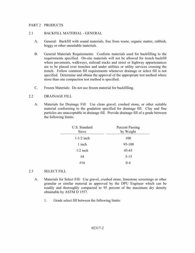
02317-2
PART 2 PRODUCTS
2.1 BACKFILL MATERIAL - GENERAL
A. General: Backfill with sound materials, free from waste, organic matter, rubbish, boggy or other unsuitable materials.
B. General Materials Requirements: Conform materials used for backfilling to the
requirements specified. On-site materials will not be allowed for trench backfill where pavements, walkways, railroad tracks and street or highway appurtenances are to be placed over trenches and under utilities or utility services crossing the trench. Follow common fill requirements whenever drainage or select fill is not specified. Determine and obtain the approval of the appropriate test method where more than one compaction test method is specified.
C. Frozen Materials: Do not use frozen material for backfilling.
2.2 DRAINAGE FILL
A. Materials for Drainage Fill: Use clean gravel, crushed stone, or other suitable material conforming to the gradation specified for drainage fill. Clay and fine particles are unacceptable in drainage fill. Provide drainage fill of a grade between the following limits:
U.S. Standard Sieve
Percent Passing by Weight
1-1/2 inch 100 1 inch 95-100
1/2 inch 45-65 #4 5-15
#16 0-4 2.3 SELECT FILL
A. Materials for Select Fill: Use gravel, crushed stone, limestone screenings or other granular or similar material as approved by the DPU Engineer which can be readily and thoroughly compacted to 95 percent of the maximum dry density obtainable by ASTM D 1557.
1. Grade select fill between the following limits:
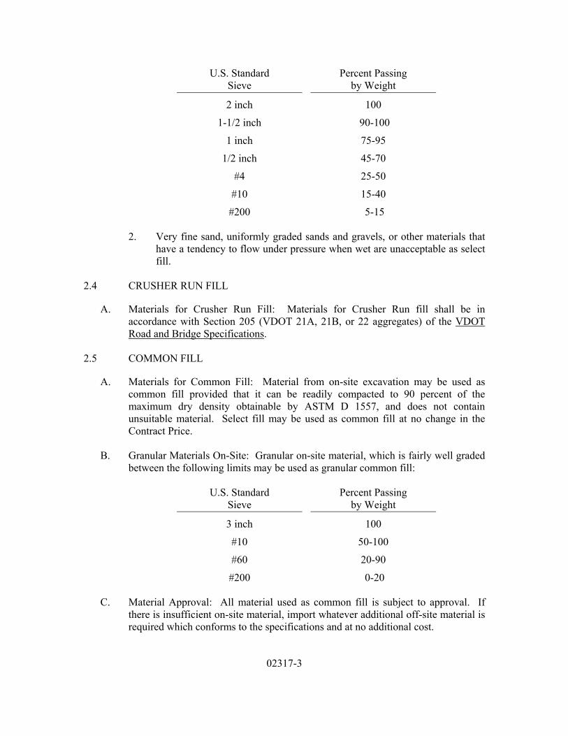
02317-3
U.S. Standard Sieve
Percent Passing by Weight
2 inch 100 1-1/2 inch 90-100
1 inch 75-95 1/2 inch 45-70
#4 25-50 #10 15-40 #200 5-15
2. Very fine sand, uniformly graded sands and gravels, or other materials that
have a tendency to flow under pressure when wet are unacceptable as select fill.
2.4 CRUSHER RUN FILL
A. Materials for Crusher Run Fill: Materials for Crusher Run fill shall be in accordance with Section 205 (VDOT 21A, 21B, or 22 aggregates) of the VDOT Road and Bridge Specifications.
2.5 COMMON FILL
A. Materials for Common Fill: Material from on-site excavation may be used as common fill provided that it can be readily compacted to 90 percent of the maximum dry density obtainable by ASTM D 1557, and does not contain unsuitable material. Select fill may be used as common fill at no change in the Contract Price.
B. Granular Materials On-Site: Granular on-site material, which is fairly well graded
between the following limits may be used as granular common fill:
U.S. Standard Sieve
Percent Passing by Weight
3 inch 100 #10 50-100 #60 20-90 #200 0-20
C. Material Approval: All material used as common fill is subject to approval. If
there is insufficient on-site material, import whatever additional off-site material is required which conforms to the specifications and at no additional cost.
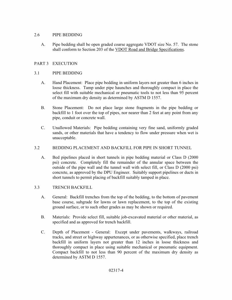
02317-4
2.6 PIPE BEDDING
A. Pipe bedding shall be open graded coarse aggregate VDOT size No. 57. The stone shall conform to Section 203 of the VDOT Road and Bridge Specifications.
PART 3 EXECUTION
3.1 PIPE BEDDING
A. Hand Placement: Place pipe bedding in uniform layers not greater than 6 inches in loose thickness. Tamp under pipe haunches and thoroughly compact in place the select fill with suitable mechanical or pneumatic tools to not less than 95 percent of the maximum dry density as determined by ASTM D 1557.
B. Stone Placement: Do not place large stone fragments in the pipe bedding or
backfill to 1 foot over the top of pipes, nor nearer than 2 feet at any point from any pipe, conduit or concrete wall.
C. Unallowed Materials: Pipe bedding containing very fine sand, uniformly graded
sands, or other materials that have a tendency to flow under pressure when wet is unacceptable.
3.2 BEDDING PLACEMENT AND BACKFILL FOR PIPE IN SHORT TUNNEL
A. Bed pipelines placed in short tunnels in pipe bedding material or Class D (2000 psi) concrete. Completely fill the remainder of the annular space between the outside of the pipe wall and the tunnel wall with select fill, or Class D (2000 psi) concrete, as approved by the DPU Engineer. Suitably support pipelines or ducts in short tunnels to permit placing of backfill suitably tamped in place.
3.3 TRENCH BACKFILL
A. General: Backfill trenches from the top of the bedding, to the bottom of pavement base course, subgrade for lawns or lawn replacement, to the top of the existing ground surface, or to such other grades as may be shown or required.
B. Materials: Provide select fill, suitable job-excavated material or other material, as
specified and as approved for trench backfill.
C. Depth of Placement - General: Except under pavements, walkways, railroad tracks, and street or highway appurtenances, or as otherwise specified, place trench backfill in uniform layers not greater than 12 inches in loose thickness and thoroughly compact in place using suitable mechanical or pneumatic equipment. Compact backfill to not less than 90 percent of the maximum dry density as determined by ASTM D 1557.

02317-5
D. Depth of Placement - Traffic Areas and Under Utilities: Where pavements,
walkways, railroad tracks and street or highway appurtenances are to be placed over trenches and under utilities or utility services crossing the trench, provide trench backfill using select fill placed in uniform layers not greater than 9 inches in loose thickness and thoroughly compacted in place with equipment as specified above. Compact backfill to not less than 95 percent of the maximum dry density as determined by ASTM D 1557.
E. Dropping of Material on Work: Do trench backfilling work in such a way as to
prevent dropping material directly on top of any conduit or pipe through any great vertical distance. Do not allow backfilling material from a bucket to fall directly on a structure or pipe and, in all cases, lower the bucket so that the shock of falling earth will not cause damage.
F. Distribution of Large Materials: Break lumps up and distribute any stones, pieces
of crushed rock or lumps which cannot be readily broken up, throughout the mass so that all interstices are solidly filled with fine material.
3.4 STRUCTURE BACKFILL
A. Use of Select Fill: Use select fill underneath all structures, and adjacent to structures where pipes, connections, electrical ducts and structural foundations are to be located within this fill. Use select fill beneath all pavements, walkways, and railroad tracks, and extend to the bottom of pavement base course or ballast. On-site materials shall not be used.
1. Place backfill in uniform layers not greater than 8 inches in loose thickness
and thoroughly compact in place with suitable approved mechanical or pneumatic equipment.
2. Compact backfill to not less than 100 percent of the maximum dry density as
determined by ASTM D 1557.
B. Use of Common Fill: Use common granular fill adjacent to structures in all areas not specified above, unless otherwise shown or specified. Select fill may be used in place of common granular fill at no additional cost.
1. Extend such backfill from the bottom of the excavation or top of bedding to
the bottom of subgrade for lawns or lawn replacement, the top of previously existing ground surface or to such other grades as may be shown or required.
2. Place backfill in uniform layers not greater than 8 inches in loose thickness
and thoroughly compact in place with suitable equipment, as specified above.

02317-6
3. Compact backfill to not less than 90 percent of the maximum dry density as determined by ASTM D 1557.
3.5 DRAINAGE BLANKET
A. Drainage Fill Placement: Provide a drainage blanket where shown consisting of drainage fill.
1. Place drainage fill underneath all structures and adjacent to structures where
pipes, connections, electrical ducts and structural foundations located within this fill, in uniform layers not greater than 8 inches in loose thickness. Compact drainage fill with suitable mechanical or pneumatic equipment to not less than 95 percent of the maximum dry density as determined by ASTM D 1557.
2. Place drainage fill adjacent to structures in all areas not specified above in
uniform layers not greater than 8 inches in loose thickness. Compact drainage fill with suitable mechanical or pneumatic equipment to not less than 90 percent of the maximum dry density as determined by ASTM D 1557.
3.6 COMPACTION EQUIPMENT
A. Equipment and Methods: Carry out all compaction with suitable approved equipment and methods.
1. Compact clay and other cohesive material with sheep's-foot rollers or similar
equipment where practicable. Use hand held pneumatic tampers elsewhere for compaction of cohesive fill material.
2. Compact low cohesive soils with pneumatic-tire rollers or large vibratory
equipment where practicable. Use small vibratory equipment elsewhere for compaction of cohesionless fill material.
3. Do not use heavy compaction equipment over pipelines or other structures,
unless the depth of fill is sufficient to adequately distribute the load.
4. Drop-hammers are acceptable for confined areas less than 3 feet across. 3.7 FINISH GRADING
A. Final Contours: Perform finish grading in accordance with the completed contour elevations and grades shown and blend into conformation with remaining natural ground surfaces.
1. Leave all finished grading surfaces smooth and firm to drain.

02317-7
2. Bring finish grades to elevations within plus or minus 0.10 foot of elevations or contours shown.
B. Surface Drainage: Perform grading outside of building or structure lines in a
manner to prevent accumulation of water within the area. Where necessary or where shown, extend finish grading to ensure that water will be carried to drainage ditches, and the site area left smooth and free from depressions holding water.
3.8 RESPONSIBILITY FOR AFTER SETTLEMENT
A. After settlement Responsibility: Take responsibility for correcting any depression which may develop in backfilled areas from settlement within one year after the work is fully completed. Provide as needed, backfill material, pavement base replacement, permanent pavement, sidewalk, curb and driveway repair or replacement, and lawn replacement, and perform the necessary reconditioning and restoration work to bring such depressed areas to proper grade as approved.
3.9 INSPECTION AND TESTING OF BACKFILLING
A. Sampling and Testing: During the progress of the work, all backfill shall be subject to testing by a qualified testing laboratory. Sampling, testing, and laboratory methods shall be in accordance with the appropriate ASTM specifications. One compaction test shall be made for each 100 cubic yards of backfill placed from the top of bedding. Under pavements, one compaction test shall be made for each 50 cubic yards of select fill placed. Submit compaction test results to the CITY Department of Public Utilities. The CITY will be the sole judge of the adequacy of compaction.
B. Correction of Work: Correct any areas of unsatisfactory compaction by removal
and replacement, or by other methods as approved by the DPU Engineer or the DPW Permit Office.
END OF SECTION

02317-8
(NO TEXT FOR THIS PAGE)

02370-1
SECTION 02370
SLOPE PROTECTION AND EROSION CONTROL
PART 1 GENERAL
1.1 SUMMARY
A. Section Includes: The requirements for providing soil erosion and sediment control practices for all areas within the contract limits and other area indicated, including work designated in the permit.
B. This Section is intended for use in water distribution system projects where the
maximum line size does not exceed 24” in diameter, where the completed water distribution system will become the property of the City of Richmond.
C. Related Work Specified in Other Sections Includes:
1. Section 02230 - Site Clearing 2. Section 02316 - Excavation - Earth and Rock 3. Section 02317 - Backfilling 4. Section 02445 - Jacking, Auguring and Mining
1.2 SUBMITTALS
A. General: Provide all submittals, including the following, as specified in Division 1.
B. Standards, Criteria, and Guidelines: Comply with applicable sections of the most
recent edition of Virginia Erosion and Sediment Control Handbook by the Virginia Department of Conservation and Recreation, Division of Soil and Water Conservation, and the erosion and sediment control ordinances of the City of Richmond, Virginia.
C. Submit copies of all required permits to the OWNER before performing any work.
PART 2 PRODUCTS
A. All products shall comply with the most recent edition of Virginia Erosion and Sediment Control Handbook.
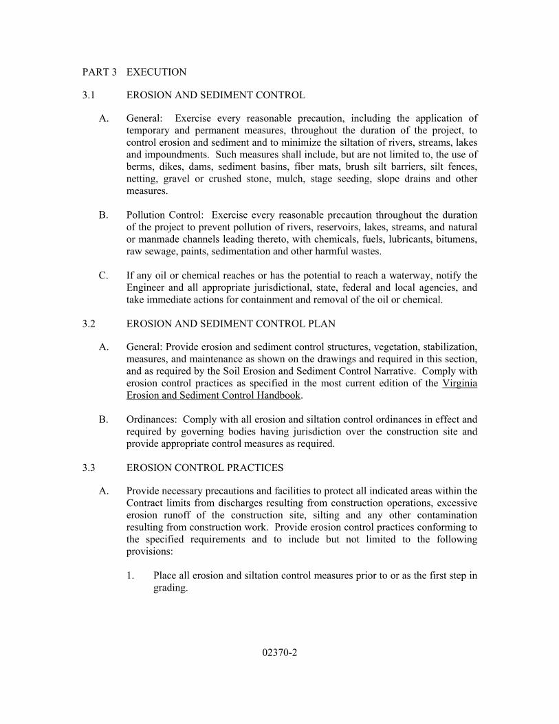
02370-2
PART 3 EXECUTION
3.1 EROSION AND SEDIMENT CONTROL
A. General: Exercise every reasonable precaution, including the application of temporary and permanent measures, throughout the duration of the project, to control erosion and sediment and to minimize the siltation of rivers, streams, lakes and impoundments. Such measures shall include, but are not limited to, the use of berms, dikes, dams, sediment basins, fiber mats, brush silt barriers, silt fences, netting, gravel or crushed stone, mulch, stage seeding, slope drains and other measures.
B. Pollution Control: Exercise every reasonable precaution throughout the duration
of the project to prevent pollution of rivers, reservoirs, lakes, streams, and natural or manmade channels leading thereto, with chemicals, fuels, lubricants, bitumens, raw sewage, paints, sedimentation and other harmful wastes.
C. If any oil or chemical reaches or has the potential to reach a waterway, notify the
Engineer and all appropriate jurisdictional, state, federal and local agencies, and take immediate actions for containment and removal of the oil or chemical.
3.2 EROSION AND SEDIMENT CONTROL PLAN
A. General: Provide erosion and sediment control structures, vegetation, stabilization, measures, and maintenance as shown on the drawings and required in this section, and as required by the Soil Erosion and Sediment Control Narrative. Comply with erosion control practices as specified in the most current edition of the Virginia Erosion and Sediment Control Handbook.
B. Ordinances: Comply with all erosion and siltation control ordinances in effect and
required by governing bodies having jurisdiction over the construction site and provide appropriate control measures as required.
3.3 EROSION CONTROL PRACTICES
A. Provide necessary precautions and facilities to protect all indicated areas within the Contract limits from discharges resulting from construction operations, excessive erosion runoff of the construction site, silting and any other contamination resulting from construction work. Provide erosion control practices conforming to the specified requirements and to include but not limited to the following provisions:
1. Place all erosion and siltation control measures prior to or as the first step in
grading.

02370-3
2. Mulch and seed all storm and sanitary sewer trenches not in streets within 15 days after backfill. Do not allow more than 300 feet of trenches to be open at any one time.
3. Place all excavated material on the uphill side of trenches where possible.
Do not place materials in stream beds. Seed any stockpiled material which remains in place longer than thirty days with temporary vegetation and mulch.
4. Mulch and seed all temporary earth berms, diversions, erosion barriers and
temporary stockpiles with temporary vegetative cover within 7 days after grading.
5. Do not stockpile or otherwise place dredged, excavated or other material, at
any time, in or near a stream bed which may increase the turbidity of the water. If turbidity producing materials are present, hold surface drainage from cuts and fills within the construction limits and from borrow and waste disposal areas in suitable sedimentation ponds or grade surface drainage to control erosion within acceptable limits. Provide and maintain temporary erosion and sediment control measures such as berms, dikes, drains, or sedimentation basins, if required to meet the above standards, until permanent drainage and erosion control facilities are completed and operative. Hold to a minimum the area of bare soil exposed at any one time by construction operations.
6. Drain wet dredged material for a minimum of 7 days. Store the material for
drainage to a maximum height of 4 feet.
7. Provide temporary erosion and sediment control measures to include but not be limited to the following:
a. Installation (and ultimate removal) of silt screens. b. Straw bales and silt traps around construction areas for all required
structures.
c. Diked area with earth berm and silt trap for draining dredged material.
d. Straw bales with silt traps along top of slope of fill area plus seeding and mulching of entire fill area not otherwise protected.
3.4 EROSION AND SEDIMENT CONTROL MEASURES
A. Unless otherwise noted, all vegetative and structural erosion and sediment control practices shall be constructed and maintained in accordance with the standards and specifications of the Virginia Erosion and Sediment Control Handbook (Latest

02370-4
Edition); Chapter 14, Article VI; and Sections 32.1-902.1 through 32.1-902.18 of the Code of the City of Richmond
3.5 STRUCTURAL PRACTICES
A. Silt Fence: Std. and Spec. 3.06. Silt fence shall be placed around the site to intercept sediment as shown on the Erosion Control Plan.
B. Storm Drain Inlet Protection: Std. and Spec. 3.07. All storm drain inlets must be
protected during construction. Gravel inlet sediment filter shall be used.
C. Culvert Inlet Protection: Std. and Spec. 3.08. All culvert inlets must be protected during construction. Silt fence culvert inlet protection or optional stone combination inlet protection shall be used.
D. Rock Check Dams: Std. and Spec. 3.20. Protect ditches from erosion and trap
sediment during construction as shown on the Erosion Control Plan.
E. Where consistent with safety and space considerations, excavated material is to be placed on the uphill side of trenches.
F. Trench dewatering devices shall discharge in a manner which will not adversely
affect flowing streams, drainage systems or off-site property.
G. Tree Protection: Std. and Spec. 3.38. Provide tree protection where shown on the Erosion and Sediment Control Plan.
H. Utility Stream Crossing: Std. and Spec. 3.28. Provide utility stream crossing
where shown on the Erosion control Plan.
I. Soil Stabilization Blankets and Matting: Std. and Spec. 3.36. Provide soil stabilization blankets and matting where shown on the Erosion Control Plan and at critical erosion areas.
J. Construction Entrance: Std. and Spec. 3.02. Provide construction entrances where
shown on the Erosion Control Plan. 3.6 VEGETATION PRACTICES
A. Temporary Seeding - Std. and Spec. 3.31. All areas rough graded during the initial phases of construction shall be seeded with fast germinating, temporary vegetation within 7 days following grading when exposed soils are not to be permanently stabilized within 30 days.
02370-5
3.7 PERMANENT STABILIZATION
A. All areas on the site which are designated for paving shall be stabilized with gravel immediately after grading. All other areas disturbed by construction shall be stabilized with permanent seeding immediately following finish grading. Graded areas shall be fertilized, seeded, and mulched according to Section 02930 of these standards.
3.8 PHASING OF LAND DISTURBING ACTIVITIES
A. Erosion and sediment controls shall be accomplished in two phases. Construction entrances, silt fence, storm drain inlet protection, culvert inlet protection, rock check dams and tree protection shall be in place before other construction begins. All other controls shall be established after rough grading and utility installation.
B. Construction shall be sequenced so that grading operations can begin and end as
quickly as possible.
C. Temporary seeding must occur within 7 days after grading. 3.9 DISPOSITION OF TEMPORARY MEASURES
A. All temporary erosion and sediment control measures shall be disposed of within 30 days after the final site stabilization is achieved or after temporary measures are no longer needed. Trapped sediment and other disturbed soil areas resulting from the disposition of temporary measures shall be permanently stabilized.
3.10 MAINTENANCE
A. All installed erosion and sediment control practices must be maintained in accordance with the requirements of the Virginia Erosion and Sediment Control Handbook (latest edition).
B. All erosion and sediment control measures must be checked daily and after each
significant rainfall. Any damage caused by rainfall or construction activities must be repaired by the close of the day. The following items must be checked in particular:
1. All seeded areas must be checked to see that a good stand is maintained.
Area must be reseeded as needed. 2. Silt fences, straw bale barrier, storm drain inlet protection, culvert inlet
protection, and rock check dams shall be checked daily and after each rain for undermining.
3. Inlet protection shall be checked daily for sediment cleanout. If
accumulation occurs, sediment shall be removed and deposited in a suitable

02370-6
area and in such a manner that it will not erode. The sediment filters shall also be checked daily to insure no damage has occurred due to construction activity.
4. No area shall be left denuded for a period longer than 14 days except that
portion of the site in which work will be continuous beyond 14 days. 3.11 EROSION AND SEDIMENT CONTROL GUIDELINES
A. Permanent or temporary soil stabilization shall be applied to denuded areas within 7 days after final grade is reached on any portion of the site. Temporary soil stabilization shall be applied within 7 days to denuded area that may not be at final grade but will remain dormant (undisturbed) for longer than 30 days. Permanent stabilization shall be applied to areas that are to be left dormant for more than one year.
B. Excess excavation disposed of off the site shall be disposed of in accordance with
the Virginia Erosion and Sediment Control Handbook.
C. Erosion and sediment controls shall be installed in accordance with Virginia Erosion and Sediment Control Handbook and shall be placed prior to or as the first step of the land disturbing activity.
D. Erosion and sediment controls shall be maintained so that sediment carrying runoff
from the site will not enter storm drainage facilities.
E. Erosion and sediment controls shall be maintained until the disturbed area is stabilized.
F. Properties adjoining the site shall be kept clean of mud or silt carried from the site
by vehicular traffic or runoff.
G. The disposal of waste materials removed from erosion and sediment control facilities and the disposal of these facilities shall be in accordance with the Virginia Erosion and Sediment Control Handbook.
H. Stabilization measures shall be applied to earthen structures such as dams, dikes
and diversions immediately after installation.
I. During construction of the project, soil stock piles shall be stabilized or protected with sediment trapping measures. The Contractor is responsible for the temporary protection and permanent stabilization of all soil stockpiles on site as well as soil intentionally transported from the project site.
END OF SECTION

02445-1
SECTION 02445
JACKING, AUGERING, AND MINING
PART 1 GENERAL
1.1 SUMMARY
A. Section Includes: Pipeline installation in casing pipe beneath highways, railroads and other structures may be installed by jacking and augering or by jacking and mining.
B. This Section is intended for use in water distribution system projects where the
maximum line size does not exceed 24” in diameter, where the completed water distribution system will become the property of the City of Richmond. This Section applies only to casing pipes carrying single water distribution pipes with no more than 20 feet of cover based on calculated pipe wall thicknesses.
C. Related Work Specified in Other Sections Includes:
1. Section 02316 - Excavation - Earth and Rock 2. Section 03310 - Cast-In-Place Concrete
1.2 REFERENCES
A. Codes and standards referred to in this Section are:
1. ASTM C 76 - Specification for Reinforced Concrete Culvert, Storm Drain, and Sewer Pipe
2. ASTM A 139 - Specification for Electric-Fusion (Arc) -Welded
Steel Pipe (NPS in 4 in. and Over)
3. OSHA PL-91-596 - Occupational Safety Health Act of 1970 Public Law 91-596
1.3 SUBMITTALS
A. Provide all submittals, including the following, as specified in Division 1.
1. Shop drawings of the jacking pipe, jacking frame, jacking head, reaction blocks, sheeting, jacking pit, receiving pit, including design calculations and the complete jacking installation.

02445-2
PART 2 PRODUCTS
2.1 MATERIALS
A. General: Use one of the following for casing piping.
1. Welded steel pipe meeting the requirements of ASTM A 139, Grade B with minimum yield strength of 35,000 psi.
2. Reinforced concrete pipe with bituminous joints, meeting the requirements
of ASTM C 76, Class V, Wall B or C.
B. Bituminous Joints: Use durable plastic coal-tar bituminous binder or compound for bituminous joint compound for reinforced concrete casing pipe. Provide compound that will adhere to the concrete surfaces and form a watertight fit or seal between the joint surfaces when they are coated with the same binder or compound and pressed together during installation.
C. Fill Material: Use fill material consisting of 1-1/4 pounds of Bentonite per gallon
of water during jacking to fill any voids between pipe and the earth.
D. Casing Spacers
1. Bands shall be 14 Gauge steel, hot rolled. Bands shall be two (2) piece for pipe through 24” diameter. Width of band shall be 8” for pipes 12” and smaller and 12” for pipe 16” and greater.
2. Liner shall be polyvinyl chloride.
3. Runners shall be 1” wide glass reinforced plastic for pipes 12” and smaller
and 2” wide glass reinforced plastic for pipes larger than 12”.
4. All studs, nuts and washers shall be cadmium plated.
5. Casing spacers shall be manufactured by PSI or an approved equal.
E. Casing Seals
1. Casing seals shall be synthetic rubber, with band locating ribs on the outside and special sealing ribs on the inside under the bands.
2. Bands shall be stainless steel.
3. Casing seals shall be manufactured by PSI or an approved equal.
02445-3
PART 3 EXECUTION
3.1 INSTALLATION
A. General: Install in accordance with the manufacturer's recommendations and approved permits.
B. Casing Spacers:
1. Secure polymer casing spacers to the carrier pipe at 6-foot (maximum)
intervals inside the casing pipe. Arrange the spacers to provide support for and to prevent floatation or shifting of the carrier pipe.
C. Conform all operations and materials to the regulations of the highway department,
railroad or other agency having jurisdiction over the crossing. Obtain the approval of all materials and methods from the agency having jurisdiction over the crossing prior to construction.
D. Rails and Skids: For bell or other type carrier pipe joints of greater diameter than
the carrier pipe barrel, arrange skids to conform to the pipe joint diameter. After the carrier pipe has been placed, fill the remainder of the annular space between the casing pipe and the carrier pipe with clean sand and seal the ends of the casing pipe with end seals unless otherwise shown, specified or directed. Brace the carrier pipe to prevent floatation or shifting.
E. Augering: Conduct augering with the proper equipment and procedure such that
the carrier pipe and the casing pipe can be installed to the grades specified without disturbing the adjacent earth. Submit all equipment and procedures for prior approval.
F. Hand Mining: Conduct hand mining only in casings that are sufficiently large
enough to permit such operation. Provide adequate fresh air supply within the casing pipe and conduct all operations in accordance with the requirements of the U.S. Department of Labor Safety and Health Regulations for Construction promulgated under the Occupational Safety and Health Act 7 1970 (PL-91-596).
G. Jacking Pit: Make the jacking pit of adequate length to provide room for the
jacking frame, the jacking head, the reaction blocks, the jacks, auger rig, and the jacking pipe. Make the pit sufficiently wide to allow ample working space on each side of the jacking frame. Make the depth of the pit such that the invert of the pipe, when placed on the guide frame, is at the elevation desired for the completed line. Provide excavation in conformance with Section 02316.
H. Sheeting: Sheet the jacking pit tightly and keep it dry at all times. Have complete
design calculation for sheeting the jacking pit sealed and submitted by a Professional Engineer registered in the State of Virginia.
02445-4
I. Jacking Frame: Use a jacking frame that applies a uniform pressure over the entire pipe wall area of the pipe to be jacked.
J. Reaction Blocks: Use reaction blocks designed to carry the thrust of the jacks to
the soil without excessive soil deflection and in such a manner as to avoid any disturbance of adjacent structures or utilities.
K. Operation: Use hydraulic jacks in the jacking operation. Use extreme care to hold
the pipe to exact line and grade. Advance the excavation at the heading manually or with an auger. Do not allow the advance to exceed one foot ahead of the casing pipe. Make every effort to avoid loss of earth outside the casing.
L. Safety Railing: Provide a safety railing all around the top of the pit at all times.
M. Jacking pit to be protected per OSHA requirements.
END OF SECTION

02445-5
(NO TEXT FOR THIS PAGE)
02500-1
SECTION 02500
LAYING AND JOINTING BURIED PIPELINES
PART 1 GENERAL
1.1 SUMMARY
A. Section Includes: This Section is intended for use in water distribution system projects where the maximum line size does not exceed 24” in diameter, where the completed water distribution system will become the property of the City of Richmond. Provide pipeline materials, coatings and linings as specified and pipe of the types, sizes and classes shown or specified.
1. Use proper and suitable tools and appliances for the safe and convenient
cutting, handling, and laying of the pipe and fittings.
2. Use approved fittings where shown and at connections or where grade or alignment changes require offsets greater than those recommended and approved.
3. Lay all underground pipelines not supported on piles or concrete cradle in
select fill bedding material, unless waived by City of Richmond Department of Public Utilities based on pipe size and local soil conditions.
4. Close off all lines with bulkheads when pipe laying is not in progress.
B. Related Work Specified in Other Sections Includes:
1. Section 02316 - Excavation - Earth and Rock 2. Section 02317 - Backfilling 3. Section 02445 - Jacking, Augering and Mining 4. Section 02512 - Disinfection 5. Section 02516 - Leakage Tests
1.2 REFERENCES
A. Codes and standards referred to in this Section are:
1. AWWA C600 - Installation of Ductile-Iron Water Mains and Their Appurtenances
2. ASTM A 307 - Specification for Carbon Steel Bolts and Studs,
60000 psi Tensile
02500-2
3. ASME B16.1 - Cast Iron Pipe Flanges and Flanged Fittings, C25, 125, 250, 800
4. ASME B16.21 - Nonmetallic Flat Gaskets for Pipe Flanges
5. AWWA C111/A21.11 - Rubber-Gasket Joints for Ductile-Iron Pressure
Pipe and Fittings
6. AWWA C115/A21.15 - Flanged Ductile-Iron Pipe With Threaded Flanges
1.3 DELIVERY, STORAGE AND HANDLING
A. Transportation and Delivery: Take every precaution to prevent injury to the pipe during transportation and delivery to the site.
B. Loading and Unloading: Take extreme care in loading and unloading the pipe and
fittings.
1. Work slowly with skids or suitable power equipment, and keep pipe under perfect control at all times.
2. Under no condition is the pipe to be dropped, bumped, dragged, pushed, or
moved in any way that will cause damage to the pipe, coating, or lining.
C. Sling: When handling the pipe with a crane, use a suitable sling around the pipe.
1. Under no condition pass the sling through the pipe.
2. Use a nylon canvas type sling or other material designed to prevent damage to the pipe and coating.
3. Do not allow chains or steel cables to come into contact with pipe or fitting.
D. Damaged Piping: If in the process of transportation, handling, or laying, any pipe
or fitting is damaged, replace or repair such pipe or pipes. Any damaged or defective material shall be brought to the attention of the DPU Engineer.
E. Blocking and Stakes: Provide suitable blocking and stakes installed to prevent
pipe from rolling.
1. Obtain approval for the type of blocking and stakes, and the method of installation.
F. Storage for Gaskets: Store gaskets for pipe joints in a cool place and protect
gaskets from sunlight, heat, oil, and grease until installed.
02500-3
1. Do not use any gaskets showing signs of checking, weathering or other deterioration.
2. Do not use gasket material stored in excess of six months without approval.
1.4 FIELD CONDITIONS
A. Repair of Sanitary Sewers and Services: Rebed, in compacted select fill material, sanitary sewers which cross over the new pipe or which cross under the new pipe with less than 12 inches clear vertical separation. Compact the bedding to densities required for new pipeline construction and extend bedding below the sewer to undisturbed earth. Reconstruct sewers damaged by pipeline construction. Conform all work to the appropriate requirements of the City Sanitary Sewer Division of the Department of Public Utilities.
1. Furnish and install all materials and do all work necessary for the
reconstruction or repairs of sanitary sewers and services.
2. Provide pipe for reconstruction of sanitary sewers and services meeting the appropriate specification requirements.
3. Provide pipe of the same size as the existing sewer. Obtain approval of joints
made between new pipe and existing pipe from the Sanitary Sewer Division of the Department of Public Utilities.
PART 2 PRODUCTS
Not Used
PART 3 EXECUTION
3.1 PREPARATION
A. Dry Trench Bottoms: Lay pipe only in dry trenches having a stable bottom.
1. Where groundwater is encountered, make every effort to obtain a dry trench bottom.
2. If all efforts fail to obtain a stable dry trench bottom and it is determined that
the trench bottom is unsuitable for pipe foundation, obtain an order, in writing, for the kind of stabilization to be constructed.
3. Perform trench excavation and backfill in accordance with Sections 02316
and 02317.

02500-4
3.2 INSTALLATION
A. General: Install all piping in accordance with the manufacturer's recommendations and approved shop drawings.
B. Code Requirements: Provide pipeline installations complying with AWWA C600
for iron pipe and as modified or supplemented by the Specifications.
C. Pipe Laying - General:
1. Generally, lay all pipe with bells pointing ahead and in accordance with plan alignment and grade.
2. Carefully place each pipe and check for alignment and grade.
3. Make adjustments to bring pipe to line and grade by scraping away or filling
in select fill material under the body of the pipe.
4. Wedging or blocking up the pipe barrel is not permitted.
5. Bring the faces of the spigot ends and the bells of pipes into fair contact and firmly and completely shove the pipe home.
6. As the work progresses, clean the interior of pipelines of all dirt and
superfluous materials of every description.
7. Keep all lines and appurtenances absolutely clean during construction.
8. Lay pipelines accurately to line and grade.
D. Pipe Laying - Trenches:
1. Carefully grade and compact pipe bedding
2. Lay all pipelines in trench excavations on pipe bedding, Class D (2000 psi) concrete cradle or other foundations as shown, specified or ordered in writing.
3. Properly secure the pipe against movement and make the pipe joints in the
excavation as required.
4. Bell Holes:
a. Cut out bell holes for each joint as required to permit the joint to be properly made and allow the barrel of the pipe to have full bearing throughout its length.

02500-5
b. Thoroughly tamp bell holes full of pipe bedding material following the making of each joint.
E. Other Foundations: Install pipelines laid on other types of foundations such as
concrete as specified, or shown on the plans, for such other foundations or as ordered in writing by the DPU Engineer.
F. Ductile Iron Pipe Mechanical Joints:
1. Assembly: In making up mechanical joints, center the spigot in the bell.
a. Thoroughly brush the surfaces with which the rubber gasket comes in
contact just prior to assembly of the joint.
b. Brush NSF approved lubricant over the gasket just prior to installation.
c. Install glands in accordance with manufacturer’s instructions.
d. Place the gasket and gland in position, bolts inserted, and the nuts tightened fingertight.
e. Tighten the nuts with a torque wrench in accordance with
manufacturers instructions.
f. Prime all bolts by dipping with a bituminous coating, except the threads. Coat threads immediately prior to installation of nuts.
G. Ductile Iron Pipe Push-On Joints:
1. Assembly: In making up the rubber gasket joint, brush the gasket seat in the socket thoroughly with a wire brush and wipe the gasket with a cloth.
a. Place the gasket in the socket with the large round end entering first so
that the groove fits over the bead in the seat.
b. Apply NSF approved lubricant evenly to the inside surface of the gasket that will come in contact with the entering pipe.
c. Brush the plain end of the pipe to be entered thoroughly and place it in
alignment with the bell of the pipe to which it is to be joined.
d. Exert sufficient force on the entering pipe so that its plain end is moved past the gasket until it makes contact with the base of the socket to make the joint.
02500-6
e. Field cut pipe assembly when necessary in accordance with the manufacturer’s instructions.
2. Positioning: Before proceeding with backfilling, feel completely around the
joint using a feeler gauge to confirm that the gasket is in its proper position.
a. If the gasket can be felt out of position, withdraw the pipe and examine the gasket for cuts or breaks.
b. If the gasket has been damaged, replace it with a new one before re-
installing the pipe.
3. Optional Mechanical Joints: Use mechanical joint fittings that meet the requirements of Section 02505 with the rubber gasket joint pipe when specified or when rubber gasket fittings are not available.
H. Temporary Bulkheads: Provide temporary bulkheads at the ends of sections where
adjoining pipelines have not been completed, and in connections built into pipelines where adjoining pipelines or structures have not been completed and are not ready to be connected.
1. Remove bulkheads encountered in connecting sewers or structures included
in this Contract, or in pipelines or structures previously built, when they are no longer needed or when ordered.
I. Sleeve Type Couplings: For sleeve type couplings, equally tighten diametrically
opposite bolts on the connection so that the gaskets will be brought up evenly all around the pipe.
1. Torque Wrenches: Do the final tightening with torque wrenches set for the
torque recommended by the coupling manufacturer.
J. Concrete Cradle
1. General: When a concrete cradle is shown, specified, or ordered in writing, lay the pipe to grade by supporting each section on concrete blocks located near each end.
a. Shape the tops of the blocks to fit the outside diameter of the pipe.
b. Set the blocks approximately 3/8 inch low.
c. Place the pipe on the blocks on a layer of stiff mortar of sufficient
thickness to bring the pipes to exact grade.
d. Timber blocking, of a type approved, may be employed in place of concrete blocks.
02500-7
2. Cradle: Place Class D concrete cradle, on one side only, until it has risen
above the invert on the other side, after which deposit the remainder of the concrete on both sides to the pipe spring line.
a. Prevent movement of the pipe during concrete placement.
K. Concrete Encasement: When concrete encasement is to be provided, as shown,
specified, or ordered in writing, lay and block the pipeline and place concrete as specified for concrete cradle.
1. Continue the placing of concrete to provide complete encasement to the
dimensions shown, specified, or ordered.
L. Valve Box Setting: Install valve boxes vertical and concentric with the valve stem.
1. Satisfactorily reset any valve box which is moved from its original position, preventing the operation of the extension valve stem.
2. Replace any extension valve stem which has been damaged so that it can be
operated.
M. Jacking:
1. General: Perform jacking in accordance with Section 02445.
N. Erection:
1. Anchorage: Place anchorage of pipelines and appurtenances as shown or as ordered.
a. Accomplish anchorage by placing concrete to the dimensions shown
between undisturbed earth and the fitting to be anchored.
2. Valve Setting: Erect valves carefully in their proper positions, free from all distortion and strain, with flanged, mechanical or push-on joints, and pack and leave in satisfactory operating condition.
3. Short Tunnel Construction: Joint pipes to be placed in short tunnels prior to
being placed into position.
a. Place the pipe into position in a manner which keeps joints tight. 3.3 FIELD QUALITY CONTROL
A. Testing: Test pipelines in accordance with Section 02516.
02500-8
1. Test valves in place, as far as practicable, and correct any defects in valves or connections.
B. Inspection: Clean, inspect, and examine each piece of pipe and each fitting and
special for defects before it is installed.
1. Cut away any lumps or projections on the face of the spigot end or the shoulder.
2. Do not use any cracked, broken, or defective pieces in the work.
3. If any defective piece should be discovered after having been installed,
remove and replace this piece with a sound piece in a satisfactory manner at no increase in Contract Amount.
3.4 CLEANING
A. General: Thoroughly clean all pipe before it is laid and keep it clean until it is accepted in the completed work.
B. Removal of Materials: Exercise special care to avoid leaving bits of wood, dirt,
and other foreign particles in the pipe. If any particles are discovered before the final acceptance of the work, remove and clean the pipe.
3.5 DISINFECTION
A. General: Disinfect all pipelines that are to carry potable water in accordance with Section 02512.
END OF SECTION

02500-9
(NO TEXT FOR THIS PAGE)
02501-1
SECTION 02501
ROADWAY AND SITE RESTORATION
PART 1 GENERAL
1.1 SUMMARY
A. Section Includes: Furnishing of all materials, labor, and equipment to repair and restore all pavements, structures and systems, both above and below the surface, removed, displaced, damaged, or otherwise disturbed during the progress of construction.
B. This Section is intended for use in water distribution system projects where the
maximum line size does not exceed 24” in diameter, where the completed water distribution system will become the property of the City of Richmond.
C. Permits: Materials, methods, and other requirements set out in permits issued by
the City of Richmond shall be complied with. When a discrepancy exists between specific permit requirements and the standards shown on the plans or specifications, the permit requirements shall govern.
D. Related Work Specified in Other Sections
1. Section 02316 - Excavation - Earth and Rock 2. Section 02317 - Backfilling
1.2 MEASUREMENT AND PAYMENT
A. General: No separate measurement will be made for the work. 1.3 REFERENCES
A. General: Virginia Department of Transportation Road and Bridge Specifications, latest edition (VDOT Specifications).
1.4 QUALITY ASSURANCE
A. General: Perform Work in accordance with VDOT Specifications.
B. Mixing Plant: Conform to VDOT Specifications.
C. VDOT Specifications: Maintain one copy of VDOT Specifications on site.
02501-2
1.5 REGULATORY REQUIREMENTS
A. General: Conform to applicable codes for paving work. 1.6 ENVIRONMENTAL REQUIREMENTS
A. Asphalt concrete installation shall be in compliance with VDOT Specifications Section 315 “Asphalt Concrete Pavement” and adhere to all requirements herein including placement limitations regarding temperature, etc.
PART 2 PRODUCTS
2.1 MATERIALS
A. Subbase and Aggregate Base Materials: Provide the material in accordance with VDOT Specifications Section 208.
B. Asphalt Materials: Provide the material in accordance with VDOT Specifications
Section 210.
C. Coarse Aggregate: Provide the material in accordance with VDOT Specifications Section 203.
D. Fine Aggregate: Provide the material in accordance with VDOT Specifications
Section 202.
E. Mineral Filler: Provide the material in accordance with VDOT Specifications Section 201.
F. Hydraulic Cement Concrete Pavement VDOT Specification Section 316 and
VDOT Road and Bridge Standards PR-2. 2.2 ACCESSORIES
A. Primer: Provide the material in accordance with VDOT Specifications Section 210 for medium curing liquid asphalt.
B. Tack Coat: Provide the material in accordance with VDOT Specifications Section
310.02. 2.3 ASPHALT CONCRETE MIX
A. General: Use dry material to avoid foaming and mix uniformly.
B. Base Course: Provide the material in accordance with VDOT Specifications Section 211 for asphalt concrete Type BM-2.
02501-3
C. Surface Course: Provide the material in accordance with VDOT Specifications
Section 211 for asphalt concrete Type SM-2A and Type SM-2C.
PART 3 EXECUTION
3.1 REMOVAL OF EXISTING PAVEMENTS
A. General: Saw cut edges of pavement in smooth continuous lines. Avoid jagged or irregular edges. Remove pavement a minimum of 12” from the edge of all excavations.
3.2 EXAMINATION
A. Subgrade Conditions: Verify subgrade conditions under provisions of Section 02317.
B. Subgrade: Verify that compacted subgrade soil is dry.
C. Finished Grade: Verify gradients and elevations of subgrade are correct.
3.3 SUBBASE
A. General: See Section 02316 and Section 02317 for preparation of the site for paving and aggregate base, and for compacted subbase for paving used to form the base construction for work under this Section.
3.4 PREPARATION - AGGREGATE BASE COURSE AND SURFACE
PREPARATION
A. General: Prepare Aggregate Base Course in accordance with VDOT Specifications Section 309.
B. Surface Preparation and Restoration: In accordance with VDOT Special Provision
(October 12, 1995) for SURFACE PREPARATION AND RESTORATION. 3.5 PREPARATION – PRIMER
A. General: Apply primer in accordance with VDOT Specifications Section 311. 3.6 PREPARATION - TACK COAT
A. General: Apply tack coat in accordance with VDOT Specifications Section 310. Apply tack coat to contact surfaces of curbs, gutters and inlet structures.
02501-4
3.7 PLACING ASPHALT CONCRETE PAVEMENT
A. General: Place asphalt concrete pavement in accordance with VDOT Specifications Section 315. Compact pavement by rolling. Do not displace or extrude pavement from position. Hand compact in areas inaccessible to rolling equipment. Develop rolling with consecutive passes to achieve even and smooth finish, without roller marks.
B. Accessories: Install manhole frames and covers and inlet grates in correct position
and elevation. Adjust existing manhole frames, valve boxes, inlet grates, and other accessories in correct position and elevation such that they meet the final road grade.
3.8 TOLERANCES
A. Flatness: Install paving with the maximum variation of 1/4 inch as measured with a 10 foot straight edge. Humps and depressions exceeding the specified tolerance shall be corrected, or the defective work shall be removed and replaced with new material.
1. Scheduled Compacted Thickness: Within 1/4 inch. 2. Variation from True Elevation: Within ½ inch.
3.9 FIELD QUALITY CONTROL
A. General: Perform field inspection and testing in accordance with the requirements contained in Division 1.
B. Protection: Immediately after placement, protect pavement from mechanical
injury. 3.10 REPAIR OF DAMAGED PAVEMENT
A. Take all reasonable precautions to prevent scratching or otherwise marring existing pavement surfaces. The defacing of existing surfaces by the use of cleated track equipment, the careless use of machine blades, the failure to keep abrasive material swept from the surface, or the spilling of liquid materials, shall be repaired to the satisfaction of the City of Richmond.
3.11 CURBS, WALKS AND ENTRANCE GUTTERS
A. Existing Structures: Existing curbs, combination curbs and gutter, entrance gutters, driveways, driveway aprons, sidewalks, and entrance walks will be cut or removed only when necessary to facilitate the installation as shown on the plans, or when efforts to bore or excavate beneath them would result in settling or structural failure.
02501-5
B. Concrete Items: In general, concrete items shall be cut or removed to the nearest existing joint where practical. The thickness, width, configuration, slope and grade of all concrete replacements shall be the same as that which was removed or damaged during construction.
C. Special Items: Areas paved with special decorative treatment, gravel, stone, brick,
block, or tile shall be restored with materials of a type, size and color resembling that which existed as closely as practicable.
3.12 DRAINAGE ITEMS
A. Storm Drain Items: Existing storm drain pipes, culverts, manholes, catch basins, curb inlets, paved ditch liners, endwalls, or any other items intended to convey storm runoff will be cut, removed or relocated only when required to facilitate the installation as shown on the plans, or when efforts to excavate or bore near them would result in settlement or structural failure.
B. Drainage Pipe: Drainage pipe, including driveway culverts, damaged by the
contractor's operations, or damaged prior to construction and requiring re-setting, shall be replaced with pipe of the same diameter, material, joint length, joint type and class. Drainage pipe dislocated for any reason due to the contractor's operations shall be reset to the line and grade which existed prior to being disturbed. The Contractor shall be responsible for setting stakes, or other reference markings, prior to excavating, for the purpose of re-establishing the original grade and alignment.
C. Storm Drainage Flow: No attempt will be made to redirect, or alter the gradient of,
any storm drainage item, except when shown on the drawings as a planned alteration to the existing system.
D. Repairs: Minor damage to drainage pipe and structures, not requiring replacement,
shall be patched or repaired, using suitable materials and methods. 3.13 SANITARY SEWERAGE ITEMS
A. Sanitary Sewers: Generally, sanitary sewer manholes and mains will be shown on the plans; however, house laterals are not normally shown and it shall be the responsibility of the Contractor to determine their exact location and depth before beginning pipeline trenching work.
B. Cutting Sanitary Sewers: Existing sanitary sewer pipes, manholes, house laterals,
or any other item intended to convey domestic sewage, will be cut, removed, or relocated only when required to facilitate the installation as shown on the plans.
C. Repairs: Sewer pipes damaged due to the Contractor's operations shall be replaced
with pipe of the same diameter, material and class. Minor damage to sewer
02501-6
appurtenances not requiring replacement shall be patched or repaired, using suitable materials and methods.
3.14 SHOULDERS AND DITCHES
A. All areas within a public right-of-way, outside of the paved roadway, including grassed areas, shoulders, swales and ditches shall be protected from damage during construction to the extent possible considering the nature of the work. The function of existing drainage channels shall not be altered unless regrading or relocation is specifically set out on the plans or is a permit requirement.
B. Flow Line Regrading: Side slopes and longitudinal grades of ditches or swales
shall be maintained or restored to those that existed prior to construction. No attempt will be made to regrade the flow line of a ditch or swale to meet the inverts of in-line culverts or storm drains, unless such re-grading would require no more than 0.5 foot of cut from the existing flow-line.
C. Roadway Shoulders: Roadway shoulders disturbed during construction shall be
re-graded with a cross-slope equal to that which existed.
END OF SECTION
02505-1
SECTION 02505
BURIED DUCTILE-IRON PIPE AND FITTINGS
PART 1 GENERAL
1.1 SUMMARY
A. Section Includes: Requirements for providing buried ductile-iron pipe, fittings and appurtenances, except soil pipe. This Section is intended for use in water distribution system projects where the maximum line size does not exceed 24” in diameter, where the completed water distribution system will become the property of the City of Richmond.
1. Provide ductile-iron pipe and fittings complete with all necessary jointing
facilities and materials, specials, adapters and other appurtenances required for installation in and completion of the pipelines to be constructed.
2. Provide flanged, plain end or rubber gaskets (push-on or mechanical joint)
of the types, sizes and classes shown or specified.
3. Corrosion Survey: Projects with a minimum installation length of 500 feet shall include corrosion protection recommendations by a registered corrosion engineer or by a corrosion survey performed by the Ductile Iron Pipe Research Association (DIPRA).
B. Related Work Specified In Other Sections Includes:
1. Section 02500 - Laying and Jointing Buried Pipelines 2. Section 02512 - Disinfection 3. Section 02516 - Leakage Test 4. Section 15080 - Miscellaneous Pipe and Fittings
1.2 REFERENCES
A. Codes and standards referred to in this Section are:
1. AWWA C104/ A21.4 - Cement-Mortar Lining for Ductile-Iron Pipe and Fittings for Water
2. AWWA C105/A21.5 - Polyethylene Encasement for Ductile-Iron Piping
for Water and Other Liquids
3. AWWA C110/A21.10 - Ductile-Iron and Gray-Iron Fittings 3 In. Through 48 In., for Water and Other Liquids

02505-2
4. AWWA C111/A21.11 - Rubber-Gasket Joints for Ductile-Iron Pressure Pipe and Fittings
5. AWWA C115/A21.15 - Flanged Ductile-Iron Pipe With Threaded
Flanges
6. AWWA C151/A21.51 - Ductile-Iron Pipe, Centrifugally Cast, for Water and Other Liquids
7. ASME B16.1 - Cast Iron Pipe Flanges and Flanged Fittings
8. AWWAC606 - Grooved and Shouldered Type Joints
9. ASTM A 307 - Carbon Steel Externally Threaded Standard
Fasteners 1.3 SYSTEM DESCRIPTION
A. Design Standards: Provide ductile-iron pipe meeting the requirements of AWWA C151/A21.51.
1. Provide pipe of the various sizes and classes as specified in the schedule or
shown on the drawings. Pipe shall be a minimum thickness as follows. Locate restrained joints and various beddings as shown on the water system details in this document.
Exception: Provide minimum Thickness Class 53 (Class 54 for 6” and 8”) for pipe with threaded flanges.
2. Construct concrete encasements where shown.
Nominal Diameter Thickness Class 3-inch Class 51 4-inch Class 53 6-inch Class 54 8-inch Class 54 10-inch Class 52 12-inch Class 52 Greater than 12-inch Class 52
02505-3
PART 2 PRODUCTS
2.1 MANUFACTURERS
A. Acceptable manufacturers are listed below. Manufacturers of equivalent products may be submitted.
1. Ductile-iron pipe and fittings.
a. American Cast Iron Pipe Company b. McWane Incorporated c. Griffin Pipe Products, Incorporated d. United States Pipe and Foundry
2. Ductile-iron retainer glands.
a. Ebba Iron, Inc. Megalug
3. Restrained push-on joints.
a. U.S. Pipe and Foundry TR Flex b. McWane Inc. Super-Lock c. American Cast Iron Pipe Company Lok-Ring or Flex-Ring d. Griffin Pipe Products Snap-Lok
4. Gaskets.
a. John Crane, Inc. b. Garlock Packing Company c. U.S. Rubber Company d. American Cast Iron Pipe Company e. United States Pipe and Foundry f. McWane Inc.
5. Stainless steel tapping sleeves.
a. Rockwell b. JCM c. Mueller
2.2 MATERIALS
A. Fittings: Provide all fittings meeting the requirements of AWWA C110/A21.10, unless shown or specified otherwise. All fittings shall have a minimum pressure rating of 250 psi. 1. Flanged: Where long radius flanged fittings and other flanged fittings not
covered in AWWA C110/A21.10 are shown or specified, provide items

02505-4
meeting the requirements of AWWA C110/A21.10 and having laying lengths conforming to ASME B16.1 for 125-pound American Standard fittings.
B. Flanged Joints
1. Threaded Flanges: Provide threaded, ductile-iron long hub flanges meeting
the requirements of AWWA C115/A21.15.
a. Screw flanges on the threaded end of the pipe in the shop. b. Reface the face of the flange and the end of the pipe together. c. Design flanges to prevent corrosion of the threads from the outside
and to prevent leakage through the pipe threads.
2. Facing and Drilling: Provide flanges plain faced and drilled to the requirements of AWWA C115/A21.15, unless special drilling is called for or required. Face flange accurately at right angles to the pipe axis. Drill flanges smooth and true, and cover machined faces with zinc dust and tallow or equivalent material.
3. Taps: Tap flanges where tap or stud bolts are required.
4. Fasteners: Provide bolts, stud bolts, and nuts meeting the requirements of
ASTM A 307, Grade B.
5. Gaskets: Provide full-face gaskets for flanged joints on 12-inch diameter and smaller pipe and gaskets of the ring type for flanged joints on larger pipe. Provide flange gaskets meeting the requirements of AWWA C115/A21.15.
C. Rubber Gasket Joints: Provide mechanical joints and push-on type joints meeting
the requirements of AWWA C111/A21.11.
D. Harnessing: For ductile-iron pipe and fittings with mechanical joints that require harnessing, provide ductile-iron mechanical joint retainer glands.
1. Coatings: Coat the assembly with two heavy coats of asphalt varnish
conforming to AWWA C151/A21.51 after installation.
2. Joint Assemblies: Design the joint assemblies to resist pullout of the joints at the test pressures specified.
3. Submit and obtain approval for the details of the joint assemblies.
4. Joint restraint by the use of gripper rings or other devices to restrain pipe
without weldments will not be permitted except with the prior approval of the OWNER.
02505-5
5. Joint restraint by the use of external rods shall not be permitted except with the prior approval of the OWNER.
E. Sleeves: Provide mechanical joint solid sleeves meeting the requirements of
AWWA C110/A21.10 where shown, specified or required for connection to existing facilities. Tapping sleeves shall be mechanical joint split sleeves with ANSI B16.1 flanged outlet or Type 304 stainless steel split sleeve with ductile iron outlet flange meeting ANSI B16.1 flanged outlet. Stainless steel sleeves shall be furnished with stainless steel bolts.
F. Wall Castings, Connecting Pieces, and Special Fittings
1. General: Provide wall castings and connecting pieces, such as bell and bell,
bell and spigot, bell and flange, flange and flange, flange and spigot, and flange and flare, meeting the requirements of AWWA C110/A21.10.
2. Design: Provide special fittings, where required, of an approved design that
have the same diameters and thicknesses as standard fittings, unless otherwise required, but their laying lengths and other functional dimensions are determined by their positions in the pipeline and by the particular piping materials to which they connect.
3. Intermediate Collar: Where watertightness is essential and at other locations
where indicated, provide wall castings with an integrally cast intermediate collar located at the center of the wall.
G. Temporary Bulkheads: Provide temporary bulkheads at the ends of sections where
adjoining pipelines have not been completed and are not ready to connect.
1. Remove all temporary bulkheads when they are no longer needed.
H. Linings and Coatings
1. Cement Lining: Provide ductile-iron pipe and fittings having a cement-mortar lining not less than standard thickness meeting the requirements of AWWA C104/A21.4, unless shown or specified otherwise.
2. Asphaltic Coating: Shop coat pipe which is to be buried with the standard
asphaltic outside coating specified in AWWA C151/A21.51.
3. Corrosion Protection: Provide exterior coatings, including polyethylene encasement, tape wrap coatings, or other coatings in accordance with the recommendations of a corrosion engineer or a DIPRA corrosion survey.
4. Encased Pipe: Do not coat or paint the outside of fittings and pipe which are
to be encased in concrete.

02505-6
5. Labels: Paint the size, class designation, manufacture date, and control number cross referenced to the laying schedule conspicuously in white on the outside of each pipe, fitting, and special casting after the shop coat has hardened.
6. Flange Joints: Immediately after facing and drilling, coat the back of the
flanges and bolt holes with asphaltic coating meeting the requirements of AWWA C151/A21.51, Section 51-8.1.
PART 3 EXECUTION
3.1 INSTALLATION
A. Install all buried ductile iron pipe and fittings in accordance with the manufacturer's recommendations and as specified in Section 02500.
3.2 LEAKAGE TESTING
A. Cleaning: Flush clean and test all pipes after installation.
B. Testing: Test pipes for leaks and repair or tighten as required.
C. Procedures: Conduct tests in accordance with Section 02516. 3.3 DISINFECTION
A. General: Disinfect all pipelines that are to carry potable water before they are placed into service as specified in Section 02512.
3.4 JOINT DEFLECTION
A. Joint deflection of any single joint shall not exceed 50 percent of the manufacturer’s allowable deflection for the type of joint to be used.
END OF SECTION

02512-1
SECTION 02512
DISINFECTION
PART 1 GENERAL
1.1 SUMMARY
A. Section Includes: Disinfection of all pipelines and equipment which are to store, handle, or carry potable water. Furnish all labor, water, chemicals, and equipment including taps, corporation stops, backflow preventers, temporary pumps, and other items necessary to perform the Work except as otherwise specified.
B. This Section is intended for use in water distribution system projects where the
maximum line size does not exceed 24” in diameter, where the completed water distribution system will become the property of the City of Richmond.
1.2 REFERENCES
A. Codes and standards referred to in this Section are:
1. AWWA C651 - Disinfecting Water Mains 2. Virginia Department of Health Waterworks Regulations
- Disinfection of Water Mains, VR 355-18-012-11. 1.3 QUALITY ASSURANCE
A. Disinfection Standards: Disinfect in accordance with AWWA C651 for water mains and AWWA C652 for water storage facilities and equipment.
B. Local Requirements: Conform disinfection procedures to Virginia Department of
Health regulations for new water mains and structures, appurtenant equipment and for cutting into existing mains.
C. Chlorinated Water Disposal: Dispose of highly chlorinated water in accordance
with applicable regulations. Disposal is the responsibility of the Contractor and shall be in such a manner as to cause no adverse environmental effects. Disposal of chlorinated water into ditches, creeks, storm or combined sewers, canals or rivers will not be permitted.
PART 2 PRODUCTS
NOT USED
02512-2
PART 3 EXECUTION
3.1 APPLICATION
A. Disinfection Procedures for Piping: Flush pipelines with clean water before disinfecting. Disinfect by the continuous feed method, as specified in AWWA C651, using sodium hypochlorite or calcium hypochlorite solution. Provide and install a City portable water meter and backflow preventer in the water supply line between the chlorination equipment and the existing water system. Then add chlorinated water containing not less than 50 mg/l free available chlorine at one end of the section being disinfected and discharged at the far end.
1. Add the chlorinated water until the water coming from each downstream
blowoff has a residual of not less than 25 mg/l of chlorine. Operate and flush all hydrants and valves.
2. Close the pipelines and allow the solution to remain in the lines for at least
24 hours. Recheck the chlorine residual in the pipeline. If the free chlorine residual is less than 10 mg/l after 24 hours, disinfect the pipelines again with more concentrated chlorinated water.
3. After meeting the previous requirements in this subsection and after a 24-
hour holding period, thoroughly flush out the pipelines and equipment and fill with clean water. Do not permit flushing water to discharge into existing water mains.
B. Continuous Feed Method: Water from the existing distribution system or other
approved sources of supply shall be made to flow at a constant, measured rate into the newly-laid pipeline. The water shall receive a dose of chlorine, also fed at a constant, measured rate. The two rates shall be proportioned so that the chlorine concentration in the water in the pipe is maintained at a minimum of 50 mg/L available chlorine. To assure that this concentration is maintained, the chlorine residual shall be measured at intervals not exceeding 2,000 feet in accordance with the procedures described in the current edition of Standard Methods and AWWA Manual M12 – Simplified Procedures for Water Examination. In the absence of a meter, the rate may be determined either by placing a pilot gage at the discharge or by measuring the time to fill a container of known volume. Table 1 gives the amount of chlorine required for each 100 ft. of pipe of various diameters. Solutions of 1 percent chlorine may be prepared with sodium hypochlorite or calcium hypochlorite. The latter solution requires approximately 1 lb. of calcium hypochlorite in 8.5 gal. of water.

02512-3
TABLE 1
CHLORINE REQUIRED TO PRODUCE 50 MG/L CONCENTRATION IN 100 FT. OF PIPE – BY DIAMETER
PIPE SIZE IN.
100 PERCENT CHLORINE
LB.
1 PERCENT CHLORINE SOLUTIONS
GAL.
4 0.027 0.33 6 0.061 0.73 8 0.108 1.30
10 0.170 2.04 12 0.240 2.88 16 0.430 5.12 20 0.675 8.00
During the application of the chlorine, valves shall be manipulated to prevent the treatment dosage from flowing back into the line supplying the water. Chlorine application shall not cease until the entire main is filled with the chlorine solution. The chlorinated water shall be retained in the main for at least 24 hours, during which time all valves and hydrants in the section treated shall be operated in order to disinfect the appurtenances. At the end of this 24 hour period, the treated water shall contain no less than 10 mg/L chlorine throughout the length of the main.
C. Disinfection Procedures for Cutting into Existing Mains:
1. The interior of all pipe and fittings (particularly couplings and sleeves) used in making the repair / connection shall be swabbed or sprayed with a 1% hypochlorite solution before they are installed.
2. Thorough flushing is the most practical means of removing contamination
introduced during repairs / connections. If valve and hydrant locations permit, flushing toward the work location from both directions is recommended. Flushing shall be started as soon as the repairs / connections are completed and shall be continued discolored water is eliminated.
3. When practical, in addition to the procedures above, the section of main in
which the repair / connection is located shall be isolated, all service connections shut off and the section flushed and chlorinated as described in Section 5.2, except the dose may be increased to as much as 300 mg/l and the contact time reduced to as little as 15 minutes. After chlorination, flushing shall be resumed and continued until discolored water is eliminated and the water is free of noticeable chlorine odor.
4. Bacteriological samples shall be taken after repairs / connections are
completed to provide a record for determining the procedure’s effectiveness. If the direction of flow is unknown, then samples shall be taken on each side
02512-4
of the break / connection. If positive bacteriological samples are recorded, then the situation shall be evaluated by the purchaser or the purchaser’s representative who can determine corrective action, and daily sampling shall be continued until two (2) consecutive negative samples are recorded.
3.2 VERIFICATION OF DISINFECTION
A. Final Samples: Bacteriological samples will be taken and tested by the OWNER on two successive days at each sampling point. At least three sampling points shall be tested. Sampling points shall be spaced at regular intervals, not exceeding 2000 feet, along the pipeline. If the samples are not satisfactory, repeat the entire disinfection procedure. Sampling shall be continued until two (2) consecutive negative samples are recorded. The selection of sampling points, the collection and identification of samples, and the evaluation of laboratory test reports shall be done by the OWNER.
1. The Contractor shall assume the expense of taking and testing additional
samples until satisfactory samples are obtained.
2. The Contractor shall assume the expense of all water for testing of the pipelines and equipment.
3.3 PLACING OF WATER MAINS INTO SERVICE
A. Water mains shall be placed into service within 5 days following verification of disinfection. Should the water main not be placed into service following initial disinfection. An additional round of disinfection and verification shall be conducted.
END OF SECTION

02512-5
(NO TEXT FOR THIS PAGE)
02514-1
SECTION 02514
HYDRANTS
PART 1 GENERAL
1.01 SUMMARY
A. Section Includes: Providing hydrants as indicated. 1.02 REFERENCES
B. Codes and standards referred to in this Section are:
1. AWWA C502 - Dry Barrel Fire Hydrants
PART 2 PRODUCTS
2.01 MANUFACTURERS
A. Acceptable manufacturers are listed below:
1. Hydrants
a. US Pipe Metro b. Mueller Centurion c. Kennedy Valve
2.02 GENERAL
B. Fire hydrants shall comply with AWWA standard C-502 and as modified or supplemented herein.
C. Fire hydrants shall be four feet bury length.
D. The nominal diameter of the main valve shall be 4-1/2 inches.
E. The hydrant inlet shall be six (6) inch mechanical joint. Each hydrant shall be
supplied with; one follower ring, one gasket, and the necessary nuts and bolts. Gaskets shall conform to the requirements of City of Richmond Specification 5-G-73.
F. The hydrant shall open right (i.e. clockwise).

02514-2
G. The hydrant shall have the main valve open against the pressure and closing with the pressure.
H. The fire hydrant shall have two 2-1/2 inch nozzle outlets at 180 degrees apart with
a 4-1/2 inch pumper nozzle outlet between. Nozzles shall use a bayonet type or breach lock method of securing from blowout. Nozzles shall have City of Richmond special threads.
I. Nozzle caps shall be individually attached to the standpipe with heavy duty, mist-
proofed, non-kinking chains that permit free turning of the cap. J. Fire hydrants shall be the safety flange traffic type. The standpipe sections shall
be connected approximately 2-3/4 inches above the ground line by a two-part safety flange with split 360 degree breakaway coupling. The hydrant, safety flange, and safety coupling for the operating rod shall be designed so as to prevent flooding if the fire hydrant is struck by a vehicle. Breakaway bolts, lugs or keeper pieces will not be acceptable. 'The standpipe and safety flange design shall permit rotation of the hydrant nozzles to any desired position without excavation or disassembly of the operating components.
K. Fire hydrant shall be the dry bonnet type. The hydrant shall be constructed with a
moisture proof lubrication chamber with enclosed operating threads which provides automatic lubrication of the threads and bearing surfaces each time the hydrant is operated. This assembly shall include at least three “O” ring seals. The top “O” ring shall keep out dirt and moisture, and the two lower "O" rings shall serve as pressure seals.
L. Threaded-on joints or threaded-on flanges above or below the ground will not be
allowed for the barrel assembly.
M. The main valve operating rod shall be designed with a travel stop so that the rod cannot be placed in compression and possibly deformed. A safety stem coupling on the operating rod shall be placed between the ground line and the standpipe safety flange.
N. The main valve shall be made of synthetic SBR rubber and formed to fit the valve
seat accurately. The main valve seat ring shall be made of bronze, and its assembly into the hydrant shall involve bronze to bronze thread engagement. The bronze subseat shall be permanently installed in the hydrant elbow and shall be an integral part thereof. “O” ring seals shall be provided as a positive seal between the scat ring and the bronze subseat. Both “O” rings shall seal between bronze parts. The hydrant shall be designed to allow the removal of all operating parts through the standpipe without excavation.
O. The drain mechanism shall be designed to operate automatically and shall allow a
momentary flushing of the drain ports each time the hydrant is operated. The drain

02514-3
ports shall be fully closed when the hydrant valve is more than four turns open. To assure positive drainage a minimum of two drain ports shall be required.
P. The operating nut shall be ductile iron or cast iron and act as a weather cap to
prevent rain or dirt from entering the opening between the nut and the top of the hydrant head.
Q. The hydrant bonnet, upper barrel, lower barrel, and elbow shall be made of ductile
iron.
R. Barrel extension section shall be available in six inch increments, complete with rod extension couplings and the necessary flanges, gaskets, and bolts so that extensions can be made without excavation.
S. The manufacturer shall furnish to the Department of Public Utilities with each
shipment, an affidavit certifying that the hydrants and all materials used in their construction conform to the requirements of this specification and AWWA Standard C-502 (latest revision) where applicable.
T. Hydrants shall be rated for a working pressure of 250 psi and hydrostatically tested
to 500 psi. Satisfactory completion of these tests and all applicable testing requirements of AWWA Standard C502 (latest revision) shall be certified by the manufacturer.
PART 3 EXECUTION
3.01 INSTALLATION
A. Install all fire hydrants in accordance with the manufacturer's recommendations. 3.02 PAINTING
B. Paint all fire hydrants according to the requirements of AWWA C502. Paint with a coat of primer and aluminum paint.
END OF SECTION

02514-4
(NO TEXT FOR THIS PAGE)
02516-1
SECTION 02516
LEAKAGE TESTS
PART 1 GENERAL
1.1 SUMMARY
A. Section Includes: Testing for any signs of leakage in all pipelines and structures required to be watertight. This Section is intended for use in water distribution system projects where the maximum line size does not exceed 24” in diameter, where the completed water distribution system will become the property of the City of Richmond.
B. Operation of Existing Facilities: The Contractor shall conduct all tests in a manner
to minimize as much as possible any interference with the day-to-day operations of existing facilities or other contractors working on the site.
1.2 PERFORMANCE REQUIREMENTS
A. Written Notification of Testing: The Contractor shall provide written notice when the work is ready for testing, and make the tests as soon thereafter as possible.
1. Furnish personnel for reading meters, gauges, or other measuring devices.
2. Furnish all other labor, equipment, air, water and materials, including
meters, gauges, smoke producers, blower, pumps, compressors, fuel, water, bulkheads and accessory equipment.
3. City of Richmond Department of Public Utilities will provide personnel to
witness pressure tests. 1.3 REFERENCES
A. Codes and standards referred to in this Section are:
1. AWWA C 600 - Installation of Ductile-Iron Water Mains and Their Appurtenances
1.4 SUBMITTALS
A. General: Provide all submittals, including the following: B. Testing Report: Prior to placing the system in service submit for review and
approval a detailed bound report summarizing the leakage test data, describing the

02516-2
test procedure and showing the calculations on which the leakage test data is based.
PART 2 PRODUCTS
NOT USED
PART 3 EXECUTION
3.1 PRESSURE TESTS OF WATER MAINS
A. Testing: Completely backfill all harnessed sections of buried piping before such sections are tested.
1. Pressure test buried or concealed pipelines for leakage by maintaining the
fluid in the pipe at the specified pressure for a minimum period of 2 hours. Pressure test shall be witnessed by a DPU inspector.
2. Pressure test the piping for leakage as a whole or in sections, valved or
bulkheaded at the ends. Apply the specified pressure to the piping through a tap in the pipe by means of a hand pump or other approved method. Do not use air for testing.
B. Test Pressures: Test the piping at the test pressures at 1 ½ times the working
pressure of the zone (determined by CITY personnel) or 150 psi, whichever is greater.
C. Allowable Leakage: Stop all visible leakage. Do not allow leakage for any piping,
as determined by the above test, to exceed the allowable leakage for ductile iron water mains as given by the following formula in Section 4.2 of AWWA C600:
L = S x D x (P)1/2 133,200
in which L is the allowable leakage in gallons per hour, S is the length of water main tested in feet, D is the nominal diameter of the pipe in inches and P is the average test pressure in psi gauge. The table below shows allowable leakage rates for pipe sizes 3”-24” for 150 psi test pressure.
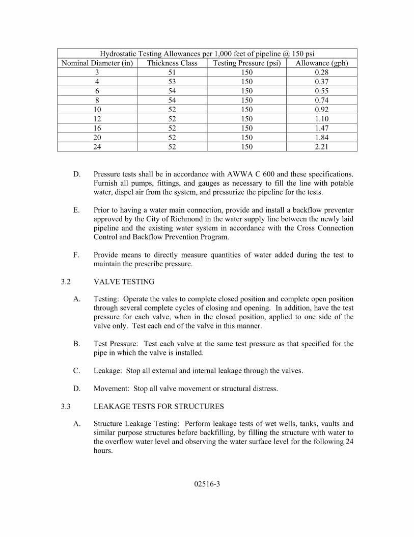
02516-3
Hydrostatic Testing Allowances per 1,000 feet of pipeline @ 150 psi Nominal Diameter (in) Thickness Class Testing Pressure (psi) Allowance (gph)
3 51 150 0.28 4 53 150 0.37 6 54 150 0.55 8 54 150 0.74
10 52 150 0.92 12 52 150 1.10 16 52 150 1.47 20 52 150 1.84 24 52 150 2.21
D. Pressure tests shall be in accordance with AWWA C 600 and these specifications. Furnish all pumps, fittings, and gauges as necessary to fill the line with potable water, dispel air from the system, and pressurize the pipeline for the tests.
E. Prior to having a water main connection, provide and install a backflow preventer
approved by the City of Richmond in the water supply line between the newly laid pipeline and the existing water system in accordance with the Cross Connection Control and Backflow Prevention Program.
F. Provide means to directly measure quantities of water added during the test to
maintain the prescribe pressure. 3.2 VALVE TESTING
A. Testing: Operate the vales to complete closed position and complete open position through several complete cycles of closing and opening. In addition, have the test pressure for each valve, when in the closed position, applied to one side of the valve only. Test each end of the valve in this manner.
B. Test Pressure: Test each valve at the same test pressure as that specified for the
pipe in which the valve is installed.
C. Leakage: Stop all external and internal leakage through the valves.
D. Movement: Stop all valve movement or structural distress. 3.3 LEAKAGE TESTS FOR STRUCTURES
A. Structure Leakage Testing: Perform leakage tests of wet wells, tanks, vaults and similar purpose structures before backfilling, by filling the structure with water to the overflow water level and observing the water surface level for the following 24 hours.
02516-4
1. Make an inspection for leakage of the exterior surface of the structure, especially in areas around construction joints.
2. Leakage will be accepted as within the allowable limits for structures from
which there are no visible leaks.
3. If visible leaks appear, repair the structure by removing and replacing the leaking portions of the structure, waterproofing the inside, or by other methods approved.
3.4 TEST APPROVAL
A. Testing: Do all performance tests, include bacteriological and pressure testing, prior to connecting new pipeline with the existing water system.
END OF SECTION

02516-5
(NO TEXT FOR THIS PAGE)
H:\R46321\Specs\02930.DOC 02930 - 1 Revised: September 20, 2005
SECTION 02930 FINE GRADING, SEEDING AND SODDING PART 1 - GENERAL 1.1 SUMMARY
A. This section includes seeding and sodding as required for restoration and restabilization of disturbed areas, and seeding and sodding outside of disturbed areas as directed by the Engineer, including preparation of seed and sod bed, fertilizer, lime, and mulch, within the contract limits.
B. This Section is intended for use in water distribution system projects where the
maximum line size does not exceed 24” in diameter, where the completed water distribution system will become the property of the City of Richmond.
C. Related Work Specified in Other Sections Includes:
1. Section 02230 – Site Clearing 2. Section 02316 – Excavation-Earth and Rock 3. Section 02317 – Backfilling 4. Section 02370 – Slope Protection and Erosion Control 5. Section 02445 – Jacking, Auguring and Mining
1.2 SUBMITTALS
A. Submit certificates of compliance before delivery of materials for the following
items:
1. Topsoil, seed, sod, fertilizer, lime and mulch. 1.3 REFERENCES
A. The Virginia Department of Highways and Transportation, Road and Bridge Specifications, latest edition, and the Virginia Erosion and Sediment Control Handbook shall govern material and construction methods, unless otherwise specified.
B. Horticultural methods and standards as to size and quality shall conform to "USA
Standard for Nursery Stock" of the American Association of Nurserymen, 1990 Edition.
H:\R46321\Specs\02930.DOC 02930 - 2 Revised: September 20, 2005
PART 2 - PRODUCTS 2.1 TOPSOIL
A. Topsoil shall consist of fertile, agricultural soil capable of sustaining vigorous plant growth. It shall contain not less than 1-1/2 percent organic matter and shall have a pH value between 6.0 and 7.6.
B. Topsoil shall be free of roots, rubbish and other objectionable materials such as
Bermuda Grass, Johnson Grass, Canada Thistle, Quack Grass, Poison Ivy and any material harmful to plant growth. Topsoil shall provide sufficient pore space to permit adequate root penetration.
C. Topsoil shall meet the following analysis as determined by the standard hydrometer
test. Sand, silt, and clay are as defined in AASHTO M146.
Min. Percent Max. Present
Sand - 30% 50% Silt - 30% 50% Clay - 5% 20% Humus - 3% 5%
D. Topsoil shall be used where indicated.
E. Materials available on site which meet the specified requirements may be utilized
with the permission of the Engineer. 2.2 TURF SEED
A. Grass seed shall be Piedmont Area Mixture in accordance with Table 3.32.D of the Virginia Erosion and Sediment Control Handbook. The exact mixture ratio may vary according to the discretion of the Contractor. No seed or seed additives shall be supplied by anyone other than the Contractor. Seed that becomes wet, moldy or otherwise damaged prior to seeding will not be acceptable.
2.3 FERTILIZER
A. Fertilizer shall be uniform in composition, free flowing and delivered to the site fully labeled according to applicable state fertilizer laws and shall bear the name trade name or trademark and warranty of the producer.
B. The Contractor may submit soil samples to an approved soils testing laboratory for
fertilizing recommendations. Recommendations shall be submitted to and approved by the Engineer before implementation.

H:\R46321\Specs\02930.DOC 02930 - 3 Revised: September 20, 2005
C. Otherwise, fertilize at the following rates:
1. Temporary Turf Seeding:
Supply 10-10-10 limestone or equivalent at the rate of 600 pounds per acre or 14 pounds per 1,000 square feet.
2. Permanent Turf Seeding:
Supply 600 pounds per acre of 10-10-10 limestone. Immediately prior to seeding supply 400 pounds per acre of 38-0-0 ureaform.
2.4 LIME
A. Lime shall be ground limestone containing at least 50 percent total oxides (calcium oxide plus magnesium oxide). Limestone shall be ground to such a fineness that at least 50 percent will pass through a 100 mesh sieve and 98 percent will pass through a 20 mesh sieve.
B. Supply 70 pounds per 1,000 square feet (1-1/2 tons per acre) on sandy and silty soils
or 100 pounds per 1,000 square feet (2.3 tons per acre) on clay or clay loam soils. 2.5 MULCH
A. Mulch for protection of permanent seeding shall conform to the following requirements:
1. Clean, weed free, unrotted straw (not less than 48 hours after mowing) shall
be applied at a rate of not less than 70 pounds per 1,000 square feet (1 2 tons per acre) and shall be anchored with: mulch anchoring tool (flat slopes), mulch netting, cut back and emulsified asphalt (five gallons per 1,000 square feet), Curasal (5 gallons per 1,000 square feet) Tera Tack II (20 gallons per 1,000 square feet), or Petroset (manufacturer's recommendations). On slopes 8 feet or more high, the rate of liquid binders shall be increased by 60%.
2. Mulch netting, jute or excelsior blanket.
B. Mulch utilized as temporary protection and stabilization shall conform to the above
materials requirements. Rate of application shall be as directed by the Engineer. Stone mulch will be permitted at the option of the Engineer.
C. Use either straw or cellulose wood fiber for landscaping.
PART 3 - EXECUTION 3.1 PERMANENT SEEDING
H:\R46321\Specs\02930.DOC 02930 - 4 Revised: September 20, 2005
A. Harrow, disc, or otherwise loosen subsoil to a depth of four inches. Spread topsoil
evenly over prepared subsoil to the following depths:
1. Slopes 3:1 or steeper, two inches after compaction.
2. Slopes flatter than 3:1, four inches after compaction.
B. Remove objectionable material such as stones, 1-1/2 inches or larger, clods, brush, roots, and trash from the top four inches of soil.
C. Apply lime and fertilizer at the rates specified in "PRODUCTS", and thoroughly mix
into the top six inches. Scarify the area and rake until the surface is leveled to provide a maximum of two inches in variation, and the soil is friable and of uniform fine texture.
D. Immediately prior to seeding apply additional fertilizer at the rates specified in
"PRODUCTS", and work into the top two inches of the soil.
E. Perform harrowing, discing, scarifying, and raking on the contour of slopes steeper than 3:1.
F. Moisten seedbed during periods of high temperatures and when directed by the
Engineer.
G. Apply seed mixture uniformly with mechanical power driven seeders, mechanical cyclone hand seeders or hydro seeding equipment. (Slurry for hydro seeder may contain seed and fertilizer only).
H. Culipack or roll one inch into soil in floodplain areas. Rake, roll or drag the seedbed
in all other areas, if hydro seeder or cyclone seeder is used.
I. Apply mulch, immediately after seeding, at the rates specified in "PRODUCTS".
J. Anchor mulch as specified. 3.2 MULCH ONLY
A. Perform grading as required. Place and anchor mulch only at the rates specified in "materials" where indicated and where directed by the Engineer.
3.3 TIME RESTRICTIONS
A. When permanent seeding or sodding is specified or directed, and seeding is not
allowed because of time restrictions specified in "PRODUCTS", utilize one or more
H:\R46321\Specs\02930.DOC 02930 - 5 Revised: September 20, 2005
of the following methods to prevent erosion and sedimentation until such time as permanent seeding or sodding is allowed:
1. Place and anchor straw mulch or wood chips.
2. Apply temporary seeding as described in Section 02370 of these
specifications.
3. Prepare soil as for permanent seeding and then mulch as specified; oversee during next seasonal seeding period.
4. Provide other erosion control measures acceptable to the Engineer and the
sediment control inspector.
5. Remove straw or wood chips used as temporary mulch or work into subsoil to a minimum depth of six inches prior to initiation of permanent seeding application.
3.4 MAINTENANCE OF SEEDED AREAS
A. Maintain seeded and sodded areas until receipt of final acceptance.
B. Water seeded and sodded areas as necessary to maintain adequate moisture in the upper four inches of soil and keep mowed to a height of two to three inches; do not remove more than 1/3 of the grass leaf during initial mowing. Do not mow sod until it is firmly rooted.
C. Inspect seeded and sodded areas for failures and necessary repairs.
D. Provide replacements during the specified planting seasons.
E. If turf grass stand is inadequate as determined by the Engineer, overseed and fertilize
using half of the rates originally applied, or resod.
F. If turf grass stand is over 60 percent damaged during a period of one year after final acceptance, as determined by the Engineer, reestablish following original seeding or sodding requirements.
END OF SECTION

H:\R46321\Specs\02930.DOC 02930 - 6 Revised: September 20, 2005
(NO TEXT FOR THIS PAGE)
03310-1
SECTION 03310
CAST-IN-PLACE CONCRETE
PART 1 GENERAL
1.1 SUMMARY
A. Section Includes: This Section is intended for use in water distribution system projects where the maximum line size does not exceed 24” in diameter, where the completed water distribution system will become the property of the City of Richmond.
B. Providing cast-in-place concrete as specified herein to form concrete to dimensions
as shown on the plans including the following work:
1. Reaction blocking 2. Pipe encasement 3. Manhole Structures
1.2 REFERENCES
A. Codes and standards referred to in this Section are:
1. ACI 117 - Standard Specifications for Tolerances for Concrete Construction and Materials
2. ACI 212 - Chemical Admixtures for Concrete
3. ACI 232.2R - Use of Fly Ash in Concrete
4. ACI 233R - Ground Granulated Blast Furnace Slag as a Cementitious
Constituent in Concrete.
5. ACI 301 - Specifications for Structural Concrete
6. ACI 304R - Guide for Measuring, Mixing, Transporting and Placing Concrete
7. ACI 305R - Hot Weather Concreting
8. ACI 306R - Cold Weather Concreting
9. ACI 308 - Standard Practice for Curing Concrete
03310-2
10. ACI 309R - Guide for Consolidation of Concrete
11. ACI 318 - Building Code Requirements for Structural Concrete and Commentary.
12. ACI 350R - Environmental Engineering Concrete Structures
13. ACI 503R - Use of Epoxy Compounds with Concrete
14. ASTM C 31 - Standard Practice for Making and Curing Concrete Test
Specimens in the Field
15. ASTM C 33 - Standard Specifications for Concrete Aggregates
16. ASTM C 39 - Standard Test Method for Compressive Strength of Cylindrical Concrete Specimens
17. ASTM C 94 - Standard Specifications for Ready-Mixed Concrete
18. ASTM C 138 - Standard Test Method for Unit Weight, Yield, and Air
Content (Gravimetric) of Concrete.
19. ASTM C 143 - Standard Test Method for Slump of Hydraulic-Cement Concrete
20. ASTM C 150 - Standard Specifications for Portland Cement
21. ASTM C 171 - Standard Specification for Sheet Materials for Curing
Concrete
22. ASTM C 172 - Standard Practice for Sampling Freshly Mixed Concrete
23. ASTM C 173 - Standard Test Method for Air Content of Freshly Mixed Concrete by the Volumetric Method
24. ASTM C 231 - Standard Test Method for Air Content of Freshly Mixed
Concrete by the Pressure Method.
25. ASTM C 260 - Standard Specification for Air-Entraining Admixtures for Concrete.
26. ASTM C 309 - Standard Specification for Liquid Membrane-Forming
Compounds for Curing Concrete
27. ASTM C 494 - Standard Specification for Chemical Admixtures for Concrete.
03310-3
28. ASTM C 596 - Standard Test Method for Drying Shrinkage of Mortar Containing Cement
29. ASTM C 618 - Standard Specification for Coal Fly Ash and Raw or
Calcined Natural Pozzolau for Use as a Mineral Admixture in Concrete.
30. ASTM C 827 - Test Method for Early Volume Change of Cementitious
Mixtures
31. ASTM C 989 - Standard Specification for Ground Granulated Blast-Furnace Slag for use in Concrete and Mortars.
32. ASTM C 1107 - Standard Specification for Packaged, Dry Hydraulic-
Cement Grout (Non-shrink)
33. ASTM E 1155 - Standard Test Method for Determination of FF
34. ASTM C 1315 - Standard Specification for Liquid Membrane-Forming Compounds Having Special Properties for Curing and Sealing Concrete
1.3 SUBMITTALS
A. Provide all submittals, including the following:
1. Design Mix: At least 31 days prior to start of placing concrete, submit design mix for concrete, indicating that the concrete ingredients and proportions will result in a concrete mix meeting requirements specified.
2. Hot and Cold Weather Concreting: Submit proposed methods for compliance
with cold and hot weather mixing and delivery recommendation of ACI 350R and ACI 306R.
3. Certificates:
a. Submit with each mix design, laboratory test reports and
manufacturer’s certificates attesting to conformance of ingredients with specifications. Include 28 day compressive strength test results certifying compliance with the requirements herein.
b. In case the source, brand or characteristic properties of the ingredients
need to be varied during the term of the Contract, submit revised design mix and manufacturer’s certificates.

03310-4
c. Submit certificate stating that each admixture used is identical in composition to the sample used for acceptance testing and is compatible with all other materials in the design mix.
d. Submit certificate stating that the concrete vibrator operators have the
required experience in operating the equipment.
4. Batch Tickets: Submit a delivery ticket from the concrete supplier with each batch delivered to the site setting forth the following information:
a. Name of supplier; b. Name of batching plant and location;
c. Serial number of ticket;
d. Date;
e. Truck number and batch number;
f. Specific job designation;
g. Volume of concrete (cubic yards);
h. Specific class of concrete;
i. Time loaded and amount of water added;
j. Type and brand of cement;
k. Weight of cement;
l. Maximum size of aggregates;
m. Weights of coarse and fine aggregates, respectively;
n. Type and amount of admixtures; and
o. Mix design designation.
5. Manufacturer’s Data: Submit manufacturer’s data with installation
instructions for all materials, including but not limited to, admixtures, curing compound and materials, coatings, waterstops, vapor barrier and joint materials.
6. All submittals shall state the location(s) and application(s) for each material.

03310-5
1.4 QUALITY ASSURANCE
A. Codes: The following specific codes and standards apply:
1. ACI 318 - Latest Edition, "Building Code Requirements for Structural Concrete and Commentary".
2. ACI – As referred to in the various subsections herein.
3. ASTM - as referred to in the various subsections herein.
B. Independent Testing Laboratory: The Contractor shall employ at his own expense
an independent test laboratory, approved by the Engineer, to perform the inspection and testing services specified in ACI 301, Section 1.6 – Quality Assurance.
C. Test Specimens: In addition to the above, the Contractor shall supply all concrete,
compression test molds, tamping rods, trowel, metal or glass covers, slump cone, storage box and sand necessary for making test specimens as outlined herein. The Contractor shall make, cure, and remove from molds and transport to the testing laboratory, three specimens for each sample in accordance with ASTM C172 and C31.
D. Extent of Tests: Prepare one sample for strength testing for each 100 cu.yds., or
fraction thereof, for each mixture design of concrete placed in one day.
E. Test Reports: Contractor shall fill in data on concrete test sample form and forward same with test specimens to the testing laboratory. When tests have been conducted, the contractor shall furnish the results of the tests with all pertinent data to the Engineer.
F. Deficiencies and Remedial Action: In the even that concrete strength test results
do no meet the acceptance criteria specified in ACI 301, additional tests of concrete in place as specified in ACI 301 shall be performed at the sole expense of the Contractor. In the event that tests of concrete in place do not meet the acceptance criteria specified in ACI 301, those portions of the structure affected as determined by the Engineer shall be removed and replaced in a manner acceptable to the Engineer at no additional expense to the Owner.
G. Slump Tests: The Contractor shall also check the consistency of concrete by
means of slump tests conducted in accordance with ASTM C143. The slump tests shall be made at the same time that the compression test specimens are made or as directed by the Engineer.
H. Air Content Test: The Contractor shall also test the air content in accordance with
ASTM C231. The air content test shall be made at the same time that the compression test specimens are made or as directed by the Engineer.

03310-6
I. Supervision of Tests: The making of all concrete specimens, slump and air content.
Tests shall be witnessed by the Engineer.
1.5 DELIVERY, STORAGE AND HANDLING
A. Deliver, store and handle all products and materials as follows:
1. Cement: Store cement delivered in bulk to the batching plant in weathertight bins and batch using an appropriate weighing device, in accordance with ASTM C 94.
a. Store cement in weathertight buildings, bins or silos which will
exclude moisture and contaminants. Do not use cement that has deteriorated from storage. Retest, before use, cement stored for a period longer than 6 months after the previous testing and reject it if it fails to meet all of the specified requirements. Do not use accepted cement that has been in storage for more than one year from the time of original acceptance.
b. Store cement delivered to the job site in strong, well-made bags
plainly marked with the brand, name of manufacturer and net weight. Reject packages received in a damaged condition.
2. Aggregates: Keep aggregates clean and free from all other materials during
transportation and handling. Keep them separated from each other until measured in batches and placed in the mixer.
a. Stockpile aggregates in a manner to prevent segregation unless finish
screening is provided at the batch plant.
PART 2 PRODUCTS
2.1 MATERIALS
A. Cement Requirements: Provide a cement which is a domestic product from an approved source. Use standard portland cement meeting the requirements of ASTM C 150 Type I II or Type IIA. For exposed concrete use one manufacturer of cement.
B. Fine Aggregate Requirements: Provide fine aggregate of natural sharp sand
meeting the requirements of ASTM C 33 for normal weight concrete, except as modified herein. Provide fine aggregate subjected to the test for organic impurities that will not produce a color darker than standard.
03310-7
1. Provide fine aggregate meeting the requirements of the soundness test set forth in Paragraph 8.1 of ASTM C 33. The exceptions stated in Paragraphs 8.2 and 8.3 do not apply.
C. Coarse Aggregate Requirements: Provide coarse aggregate consisting of crushed
stone meeting the requirements of ASTM C 33 for normal weight concrete.
1. The limits for deleterious substances and physical property requirements given in Table 3 of ASTM C 33 apply for each concrete class designation without exception.
2. Grade coarse aggregate according to Size No. 467 or No. 57 in Table 2 of
ASTM C 33 for Class D (2000 psi) concrete and Size No. 57 for Class A and B concrete.
D. Cementitious Admixtures: Limit the use of cementitious admixtures to the
following:
1. Fly Ash
a. Fly Ash shall conform to ASTM C618, Class F or Class C. b. As a portion of the total cementitious material, the fly ash content
shall not exceed 30 percent.
c. The maximum loss on ignition for fly ash shall not exceed 4.0 percent.
d. Fly ash shall be from a single source.
e. The use of fly ash shall conform to ACI 232.2R, “Use of Fly Ash in
Concrete”.
2. Ground Granulated Blast-Furnace Slag (GGBFS):
a. GGBFS shall conform to ASTM C989, Grade 100 or 120. b. As a portion of the total cementitious material, the GGBFS content
shall not exceed 50 percent.
c. GGBFS shall be from a single source.
d. The use of GGBFS shall conform to ACI 233R, “Ground Granulated Blast-Furnace Slag as a Cementitious Constituent in Concrete”.
E. Admixture Use: Limit the use of admixtures to the following:

03310-8
1. Air-entraining admixture conforming to ASTM C 260
2. Water-reducing admixture conforming to ASTM C 494 Type A
3. Water reducing set retarders conforming to ASTM C 494 Type D
4. Use water-reducing and set-retarding admixtures only after obtaining written permission. Provide test data indicating that the concrete containing the admixtures has improved workability and does not show any abnormal behavior such as premature stiffening or slump loss for at least 30 minutes after mixing has been completed, or any other abnormal differences when compared with concrete made without the admixture. Base such test data on fresh concrete from the proposed supplier, using batching equipment proposed for use on the project.
5. Do not use admixtures containing calcium chloride, thiocyanates or more
than 0.05 percent chloride ion. Obtain written conformance to the above requirements and the chloride ion content of each admixture from the admixture manufacturer prior to mix design review.
6. When more than one admixture is used, dispense each admixture separately
into the mix, and at different times during mixing, in accordance with the recommendation of ACI Committee 212. After system approval, make no changes in batching equipment or concrete constituents without approval.
7. The use of anti-freeze compounds, salts, chemicals or other foreign materials,
for the purpose of lowering the freezing point of the concrete is prohibited.
F. Water: Use clean water in mixing concrete which does not contain deleterious amounts of oils, acids, alkalies or organic materials, furnished only from water from approved sources.
G. Curing Covers: Provide water curing blankets consisting of an outer covering of
burlap or cotton or other approved material, and needled, punched or sandwiched inner layer of cotton batting or other approved material, in all weighing not less than 20 ounces per square yard. Use curing blankets by Midwest Canvas Corporation, Chicago, Illinois, by Max Katz, Indianapolis, IN or approved equal.
1. Use curing water having a temperature that is within 20 degrees F of the
concrete’s surface temperature.
H. Waterproof Paper and Film: Provide waterproof paper or polyethylene film both meeting the requirements of ASTM C 171 for use as sheet material curing covers and vapor barriers.
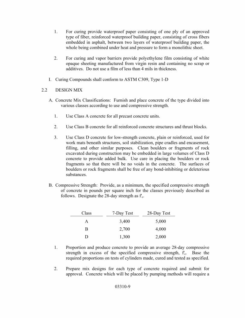
03310-9
1. For curing provide waterproof paper consisting of one ply of an approved type of fiber, reinforced waterproof building paper, consisting of cross fibers embedded in asphalt, between two layers of waterproof building paper, the whole being combined under heat and pressure to form a monolithic sheet.
2. For curing and vapor barriers provide polyethylene film consisting of white
opaque sheeting manufactured from virgin resin and containing no scrap or additives. Do not use a film of less than 4 mils in thickness.
I. Curing Compounds shall conform to ASTM C309, Type 1-D
2.2 DESIGN MIX
A. Concrete Mix Classifications: Furnish and place concrete of the type divided into various classes according to use and compressive strength.
1. Use Class A concrete for all precast concrete units.
2. Use Class B concrete for all reinforced concrete structures and thrust blocks.
3. Use Class D concrete for low-strength concrete, plain or reinforced, used for
work mats beneath structures, soil stabilization, pipe cradles and encasement, filling, and other similar purposes. Clean boulders or fragments of rock excavated during construction may be embedded in large volumes of Class D concrete to provide added bulk. Use care in placing the boulders or rock fragments so that there will be no voids in the concrete. The surfaces of boulders or rock fragments shall be free of any bond-inhibiting or deleterious substances.
B. Compressive Strength: Provide, as a minimum, the specified compressive strength
of concrete in pounds per square inch for the classes previously described as follows. Designate the 28-day strength as f'c.
Class 7-Day Test 28-Day Test
A 3,400 5,000 B 2,700 4,000 D 1,300 2,000
1. Proportion and produce concrete to provide an average 28-day compressive
strength in excess of the specified compressive strength, f'c. Base the required proportions on tests of cylinders made, cured and tested as specified.
2. Prepare mix designs for each type of concrete required and submit for
approval. Concrete which will be placed by pumping methods will require a

03310-10
separate mix design and mix design approval, as described herein, in addition to the mix design approval required for other placement methods.
C. Concrete Proportions: Select concrete proportions to provide the required strength
and durability and to provide workability and consistency so that the concrete can be worked into forms and around reinforcement without segregation or excessive bleeding.
1. The maximum water-cementitious material ratio for Class B concrete shall
not exceed 0.45 by weight of the total cementitious constituent. Class D (2000 psi) concrete shall be proportioned to meet the strength requirement. Measure the quantity of water to be the total quantity, including free surface moisture contained in the aggregates.
2. Establish concrete proportions including the water-cementitious material
ratio on the bases of field experience or trial mixtures with the materials to be used in accordance with Section 5.3 of ACI 318.
3. Grade the combined aggregates for the design mix such that when a sample
of the mix is separated on No. 4 standard sieve, the weight passing the sieve is not less than 30 percent nor greater than 40 percent of the total, unless otherwise specified
D. Air Entrainment:
1. Provide air entrained Class B and D concrete with an average total air
content of 6 percent. Allow a tolerance of plus or minus 1.0 percent on air content as delivered.
E. Slumps Range: When tested in accordance with ASTM C 143, provide a concrete
mix design with slump range within the following limits:
Concrete Placement
Minimum and Maximum Slump in Inches
Class B Class D
Normal 2 to 3 4 2 to 4 Pumped 4 to 6 4 to 6
1. Base the mix design slump on the concrete mix with water reducing
admixture. For production concrete, allow no more than 1-inch increase in slump by use of specified water reducing admixtures. Measure slump at the end of the hose for pumped concrete.
03310-11
F. Chloride Ion Concentration: Provide a maximum water soluble chloride ion concentration, percent by weight of cementitious materials, with two 28 day tests of design mix hardened concrete as follows:
1. Cast-in-place concrete, exposed to moisture or water: 0.10.
G. Measurement and Mixing: Measure and mix concrete in accordance with the
recommendations of ACI 304R, as modified.
1. Measure cement, and fine and coarse aggregates separately by weight by equipment providing an accuracy within one percent of the net load weighed. Measure cement and water within 1 percent accuracy by weight. Measure aggregates within 2 percent accuracy. Measure admixtures within 3 percent accuracy by weight.
2. Use weighing equipment meeting the requirements of the United States
Bureau of Standards. Make available standard testing weights and other necessary equipment at all times for testing the equipment.
3. Mix concrete in a rotary, batch-type mixer of adequate design to produce a
thorough mix, homogeneous in composition and uniform in color. Mix each batch of one cubic yard for less not less than 1-1/2 minutes after the last of the ingredients have been added to the mixer. Increase the mixing time 15 seconds for each cubic yard or fraction thereof.
2.3 CONCRETE WORKMATS
A. As a working base for all new, reinforced-concrete structural foundation elements supported on soil, rock, select fill, backfill stone, drainage stone and the like, provide a Class D concrete workmat having a minimum thickness of 2 inches.
2.4 READY MIX CONCRETE
A. Ready Mix Requirements: For ready-mixed concrete meet the requirements of ASTM C 94, except as modified in the following paragraphs, and subject the mix to all provisions herein relative to materials, strength, proportioning, consistency, and testing. Article 18 of ASTM C 94, however, does not apply. In the event of low strengths, procedures outlined in Section 3 4 "Low Concrete Strength Test Results" apply.
B. Delivery: Provide the rate of delivery of the mixed concrete such that the interval
between placing of fresh concrete in contact with concrete already placed from previous batches does not exceed 45 minutes. Do not allow the elapsed time between the introduction of mixing water to the cement and aggregates and depositing concrete in the work to exceed 60 minutes, including mixing and agitating time.

03310-12
C. Agitation: Do not deliver concrete in nonagitating equipment.
D. The volume of any batch mixed shall not exceed the manufacturer’s capacity of the mixer used.
E. Mixing time shall be as specified in ASTM C94, but during hot weather or other
conditions contributing to quick stiffening of concrete, the Engineer may require the Contractor to limit the discharge time to LESS than one hour or 300 revolutions of the mixer, whichever comes first.
F. No materials for a batch of concrete shall be placed in the drum of a mixer until all
the previous batch has been discharged. Mixers shall be kept free and clean of accumulations of hardened concrete and any incrustations of inert materials.
G. The effective moisture contained in the aggregate shall be included in the total
amount of mixing water used. In the absence of a field determination of the moisture content of the aggregates, the following shall be assumed: fine aggregate, ½ gallon per cubic foot and coarse aggregate ¼ gallon per cubic foot. The quantity of mixing water to be used shall include the moisture in the aggregates above the state of saturated and surface dry.
H. Water shall not be added to the mix after departure from the batching plant without
the Engineer’s permission. In no case shall the maximum water cement ratio be exceeded.
I. If it becomes necessary to mix a small portion of concrete by hand, permission
shall be obtained from the Engineer. In that case, if allowed, the total quantity of such batches shall not exceed ½ cubic yard. The materials shall be accurately measured and shall be mixed dry in a watertight, metal mortar box in order to prevent loss of cement. Mixing on the bare ground of on floors of buildings will not be permitted under any circumstances. The mass shall be thoroughly turned over at least 6 times, water being added after the third time.
J. Field Records: Prepare a detailed concrete field record in which the following
information is identified:
1. Number of concrete batches produced.
2. Proportions of materials used.
3. Approximate location of final deposit of each batch in the structure.
4. Time and date of mixing and placing.

03310-13
2.5 CONVEYING
A. Handle concrete from the mixer to the place of final deposit as rapidly as practicable by methods that will prevent segregation, undue drying or temperature rise, or loss of ingredients, and in a manner that will maintain the required quality of concrete.
B. Use conveying equipment of size and design to maintain a continuous flow of
concrete at the delivery end, and as approved by the Engineer. Do not use conveying equipment with aluminum parts, such as chutes, hoppers, or scrapers, that could come in contact with and contaminate with the concrete during conveying.
C. Use belt conveyers which are horizontal or at a slope which will cause neither
segregation nor loss. Use an approved arrangement at the discharge end to prevent separation. Discharge long runs without separation into hopper. Do not allow concrete to adhere to the return belt.
D. Use chutes which are metal or metal lined, or have a slope not exceeding one
vertical to two horizontal and not less than one vertical to three horizontal. Chutes more than 20 fee long, and chutes not satisfying slope requirements, may be used if the chutes discharge into an approved hopper before distribution.
E. Use pumping and pneumatic conveying equipment of suitable kind with adequate
pumping capacity. Clean equipment at the end of each operation. Control pneumatic placement so that separation in not apparent in the discharged concrete.
PART 3 EXECUTION
3.1 PLACING CONCRETE
A. General: Place concrete only in the presence of the ENGINEER. Where the procedure is not specified, place concrete in accordance with the recommendations of ACI 304R.
B. Placing on Ground or Subcourse: Subgrade or base course shall be free from
injurious material, well drained, and moist at time of concreting. Prior to placing concrete, thoroughly clean and dampen as necessary leaving no free water standing on base course or subgrade and no soft or muddy spots in subgrade.
C. Continuous Operation: Place no concrete after its initial set has occurred, and do
not use retempered concrete under any conditions. Make concreting operations continuous until the section, panel, or scheduled placement is completed. Should the concreting operations be unavoidably interrupted, provide construction joints formed at proper locations as specified.
03310-14
D. Minimum Handling: Convey and place concrete with minimum handling and
deposit the concrete in the forms as close as possible to its final position and in no case more than 5 feet in a horizontal direction therefrom. Do not rehandle concrete. Do not use vibrators for shifting of the mass of fresh concrete.
E. Horizontal Layers: Place concrete in horizontal layers of such thickness that the
previous layer remains plastic when the next layer is added and the two layers can be vibrated together to prevent the formation of seams or planes of weakness within the section. Layers of concrete shall not be tapered off in wedge shaped slopes but shall be built with squared ends and level tops. If a section cannot be placed continuously, locate construction joints at points as indicated or as approved. Place concrete at such a rate that all concrete being integrated with fresh concrete is plastic. Do not exceed 18 inches in depth for each layer.
F. Use of Chutes: Deposit wall and column concrete through heavy duck canvas or
galvanized steel chutes equipped with suitable hopper heads. Provide chutes of variable lengths so that the free fall of concrete does not exceed 3 feet. Provide illumination where required, inside the forms so that the concrete is visible from the deck and runways at the point of deposit.
G. Protection Against Elements: Protect freshly placed exposed concrete against
damage from the elements or other sources.
H. Hot Weather Placement: For placement of concrete during hot weather, follow the recommendations of ACI 305R.
1. Place no concrete if the temperature of the concrete at the time of placement
exceeds 90 degrees F. When the surface temperature of the reinforcing steel is greater than 120 degrees F, embedded items shall be sprayed with water immediately prior to placing concrete.
2. When the temperature of the concrete at the time of placement is consistently
above 75 degrees F and a noticeable decrease in slump or an increase in mixing water demand occurs, use a retarding admixture, after obtaining written permission to do so.
3. Protect unformed surfaces of concrete placed during hot weather from drying
by continuous moist curing for at least 24 hours. Start curing as soon as the concrete has hardened sufficiently to withstand surface damage. If moist curing is not carried beyond 24 hours, cover the surface while damp with a suitable heat-reflecting plastic membrane or spray exterior surfaces with a white pigmented dissipating curing compound in accordance with Section 3.5 Curing. Use curing water having a temperature that is within 20 degrees F of the concrete’s surface temperature.

03310-15
4. Protect formed surfaces of concrete placed during hot weather from drying as recommended in ACI 305 R.
5. Make provisions for windbreaks, shading, fog spraying, sprinkling, or wet
cover when necessary.
I. Cold Weather Placement: For placement of concrete during cold weather, follow the recommendations of ACI 306R, except that set-accelerators will not be permitted.
1. Before placement of concrete, completely remove all ice, snow and frost
from all surfaces to be in contact with the concrete. Do not place concrete on a frozen subgrade. Heat surfaces to be in contact with the concrete to a temperature as near as practical to that of the concrete being placed.
2. When mean daily temperatures at the site are below 40 degrees F provide
concrete at a temperature, as placed, of not less than 50 degrees F, except for mass concrete provide a temperature of the concrete as placed of not less than 45 degrees F. Heat aggregates or mixing water or both to obtain these placement temperatures. Do not permit the concrete temperatures as mixed to exceed the placement temperature by more than 10 degrees F for air temperatures of 0 degrees to 30 degrees F, nor by more than 15 degrees F for air temperatures below 0 degrees F.
3. Maintain concrete in place at a temperature of 50 degrees F by keeping
forms in place, covering with insulated blankets, heated enclosures or combinations of these for the following minimum time intervals, except that forms shall not be removed in less than the time specified in Section 03100.
a. Footings and walls below grade and slabs on grade 2 days
b. Exposed walls and columns carrying no load 3 days
c. Exposed floor slab, beams and girders
above grade and partially loaded 6 days
4. Protect exposed surfaces of new concrete from drying out. When dry heating is used for protection against low temperatures, cover exposed concrete surfaces with an approved sheet material or membrane as specified in Section 03100 subsection "Curing". Use water curing only if icing problems can be avoided. During periods of very cold weather, continue the protection against low temperature for an extended curing period as required to prevent freezing of the concrete.
5. Permit concrete which is to be exposed to freezing temperatures to undergo
some drying just prior to and during the period of adjustment to ambient
03310-16
cold-weather conditions. When protection against low temperatures is removed, do not allow the resulting temperature drop in any part of the concrete to exceed 5 degrees per hour nor 40 degrees F for the first 24 hour period.
J. Concrete Embedments:
1. Encase pipes, anchor bolts, sleeves, steps, castings, floor drains, manhole
frames, cast-in reglets, dovetail anchor slots, and other inserts in concrete as shown on the Plans. Take special care to place and maintain them to the proper lines and grades and to compact concrete thoroughly around them to prevent the passage of water. Insofar as possible, set them before placing concrete and sufficiently brace to prevent movement during the progress of the work.
3.2 VIBRATING CONCRETE
A. Use of Vibrators: Consolidate all concrete by means of mechanical internal vibrators applied directly into the concrete in a vertical position in accordance with the recommendations of ACI 309.
B. Vibrator Size: Provide a sufficient intensity and duration of vibration to cause
concrete to combine with previously placed concrete, to fill corners, to compact thoroughly and to embed reinforcement, pipes, conduits, and similar work completely. Insert vibrators into and withdraw from the concrete vertically at close intervals. Do not use vibrators to move concrete laterally.
C. Spare Units: Have on hand a sufficient number of vibrators to assure that the
incoming concrete can be properly compacted within 15 minutes after placing. Provide reserve vibrators for use when others are being serviced. Do not start the placement of any concrete unless more than one vibrator is available.
3.3 CONCRETE TESTS
A. Independent Testing Laboratory: The Contractor shall employ at his own expense an independent test laboratory, approved by the Engineer, to perform the inspection and test services specified herein.
B. Compression Testing: Test concrete test cylinders in compression at the laboratory
designated.
C. Samples: Take samples for strength tests of laboratory cured cylinders for tests of each class of concrete placed each day consisting of four cylinders from the same batch of concrete. Test two cylinders at 7 days and two at 28 days. Determine concrete strength by the average of the two cylinder strengths determined at either age. Take samples not less than once a day nor less than
03310-17
once for each 100 cubic yards of concrete, or 5,000 square feet of area and not less than one sample per structure.
D. Test Specimens: In addition to the above, the Contractor shall supply all concrete,
compression test molds, tamping rods, trowel, metal or glass covers, slump cone, storage box and sand necessary for making test specimens as outlined herein. The Contractor shall make, cure, and remove from molds and transport to the testing laboratory in accordance with ASTM C172 and C31.
E. Field Curing: Take samples for field cured cylinders to determine concrete
compressive strength for form removal time as required.
F. Laboratory Curing: Sample fresh concrete in accordance with ASTM C 172. Mold and laboratory cure cylinders for strength tests in accordance with ASTM C 31.
G. Slump Tests: Perform slump tests in accordance with ASTM C 143, at the same
time cylinders are made. Make tests to determine air content of fresh concrete twice daily, at least 4 hours apart, in accordance with either ASTMC 173 or ASTMC 231or with an approved testing device. Concrete with excessive slump or improper air content will be rejected. Deliver no additional concrete until the cause of the deficiency is determined and corrected.
H. Compressive Strength Test Requirements: Test cylinders in accordance with
ASTM C 39 for both the 7-day and the 28-day compressive strength. I. Test Reports: Contractor shall fill in data on concrete test sample form and
forward same with test specimens to the testing laboratory. When tests have been conducted, the contractor shall furnish the results of the tests with all pertinent data to the Engineer.
J. Successful Testing Requirements: Consider the strength level of the concrete mix
for each individual class of concrete satisfactory when: 1. The average of all sets of three consecutive 28-day strength tests (each test an
average of two cylinders) equal or exceed the specified compressive strength (f'c).
2. No individual 28-day strength test (each test an average of two cylinders)
falls below f'c by more than 500 psi.
3. If either of these requirements are not met, the Engineer may require changes in the mix proportions for the remaining concrete being poured to achieve the required strength.

03310-18
3.4 LOW CONCRETE STRENGTH TEST RESULTS
A. Tests on Hardened Concrete In-Place: In the event that concrete strength test results do not meet the acceptance criteria specified in Section 3.3, additional tests of concrete in-place as specified in ACI 301 shall be performed at the sole expense of the Contractor.
B. Acceptable Levels of Strength: Concrete in the area represented by in-place tests
will be accepted if the average of three cores is equal to or greater than 0.85 f'c and no single core is less than 0.75 f'c.
C. Unacceptable Concrete: Remove and replace those portions of the concrete
which, as determined by the Engineer, do not meet the in-place test requirements, or at the Engineer’s discretion strengthen the concrete to the satisfaction of the ENGINEER.
3.5 CURING
A. General: follow the recommendations of ACI 308 for curing concrete.
B. Protection: Protect concrete surfaces normally exposed to the atmosphere against too rapid drying by curing for a minimum period of 7 days. For hot weather concreting and cold weather concreting follow the recommendations of ACI 305R and ACI 306R respectively for curing concrete. Commence the curing period immediately following the placing of the concrete. Accomplish curing by one of the following methods. Should there be any delay in the application of the method of curing used, cover the concrete with moistened burlap held in complete contact with the surface or kept wet by continuous sprinkling. Use curing water having a temperature that is within 20 degrees F of the concrete’s surface temperature.
1. Accomplish water curing by the use of curing blankets wetted and applied to
the concrete surface as soon as the forms have been removed, or in the case of slabs, as soon as the concrete has set up sufficiently to prevent marring of the surface. Maintain the covering material in a thoroughly saturated condition and maintain the presence of free water between the mat and the surface of the concrete at all times throughout the curing period.
2. Accomplish sheet material curing by use of waterproof paper or polyethylene
film applied to the concrete surface as soon as it has set sufficiently hard to prevent marring. First, thoroughly wet the concrete surface, and then place the sheet materials in direct contact and anchor thereto in a manner to assure continuous contact throughout the curing period. Lap the sheet materials a minimum of 3 inches with the seams taped, cemented, or glued. Discoloration is objectionable on floors which have been steel troweled to a hard finish. Do not use polyethelene film on these floors.

03310-19
3. Accomplish curing by using clear residual acrylic curing and sealing compound membranes on interior concrete surfaces that do not receive a finish, overlays or hardener, and on walking surfaces. Accomplish membrane curing immediately after removal of forms or in the case of unformed surfaces, immediately after final finishing. Uniformly coat the entire exposed surface with a clear curing compound membrane by means of an approved pressure spray distributor at the rate and thickness recommended by the manufacturer, or if not stipulated, at of 300 square feet per gallon of material. Apply the material so that the concrete surface is completely coated and sealed with one application. Do not apply the membrane to faces of construction joints or other surfaces against which additional concrete will be placed. Keep such surfaces continuously wet by other means.
4. Accomplish curing by using dissipating resin type curing compounds. Apply
to all concrete surfaces except those listed in paragraph 3.5.B.3. Start curing immediately after removal of forms as in the case of unformed surfaces, immediately after final finishing while the concrete surface is still moist. Coat the entire exposed surface by means of approved pressure spray distributor at the rate and thickness recommended by the manufacturer, or if not stipulated, at 200 square feet per gallon of material. Apply the material so that the concrete surface is uniformly coated with one application. Do not apply to the faces of construction joints or other surfaces against which additional concrete will be placed. Keep such surfaces wet by other means.
3.6 JOINTS AND BONDING
A. Joints: Make construction joints where shown or permitted. Locate such joints to ensure stability, strength, and watertightness, and provide a waterstop where shown. Build all corners monolithically, and place concrete continuously on either side to points shown. The maximum horizontal distance between well joints shall be 35 feet in a continuous wall. At corners or other wall intersections a joint shall be provided in each wall a maximum horizontal distance of 20 feet from the intersection. The maximum vertical distance between wall joints shall be 12 feet.
B. Horizontal Keyways: Build horizontal keyways to permit flushing water to escape
from the keyways.
C. Keyway Description: Provide continuous, straight, and regular keys or grooves in joints. Form keyways to the dimensions shown on the Plans. Where not shown, keyways shall be 2 inches nominal depth and the width shall be equal to one-third the concrete section thickness in 2-inch increments. Bring exposed concrete surfaces to a true level line at the top of every horizontal construction joint. Provide the exposed construction joints with a row of form ties located in the concrete at from 4 to 6 inches from the joint to tighten the forms for subsequent sections. Set reinforcement to extend into subsequent sections of
03310-20
construction, as shown. If required, provide water stops having watertight splices and corner intersections and meet the requirements as specified. Remove all bulkheads or other joint forming material before placing adjacent concrete.
D. Continuous Placement Procedure: Carry on continuous placing of concrete
between the construction joints shown. If for any reason it becomes necessary to stop the placing of concrete at locations other than those indicated, such locations and the manner of making the joint are subject to approval by the Engineer.
E. Before placement of fresh concrete, clean reinforcing steel and the surfaces of
horizontal and vertical construction joints of surface laitance, curing compound, and other materials foreign to the concrete. Moisten surfaces on which concrete is to be placed with water immediately before placing concrete.
F. Surfaces of horizontal construction joints, where expansion joint filler or bond
breaking compound is to be placed as indicated, shall be cleaned of dirt, sawdust, and other loose material.
G. When it is necessary to make a construction joint because of an emergency, furnish
and place additional reinforcing steel across the joint as required at no additional expense to the Owner.
H. Concrete slabs and walls shall be poured between indicated joints allowing a
minimum period of 3 days to elapse between adjacent pours.
I. Contraction (Control) Joints in Slabs-on-Ground: Construct contraction joints in slabs-on-ground to form panels of patterns as shown. Use saw cuts 1/8" x 1/4 slab depth or inserts 1/4" wide x 1/4 of slab depth, unless otherwise indicated.
1. Form contraction joints by inserting premolded plastic, hardboard or
fiberboard strip into fresh concrete until top surface of strip is flush with slab surface. Tool slab edges round on each side of insert. After concrete has cured, remove inserts and clean groove of loose debris.
a. Contraction joints in unexposed floor slabs may be formed by saw
cuts as soon as possible after slab finishing as may be safely done without dislodging aggregate.
2. If no joint pattern is shown, provide joints not exceeding 15 feet in either
direction and located to conform to bay spacing wherever possible (at column centerlines, half bays, third-bays).
03310-21
3.7 FINISHING CONCRETE SURFACES
A. Beveling Edges: Finish top edges of walls and equipment pads with a 1/2-inch beveled edge, unless other details are shown, and rub off any burrs remaining upon removal of the forms.
B. Form Removal Inspection: Immediately after stripping the forms, inspect all
concrete surfaces. Remove all fins, offsets, burrs, ridges, or other unsightly marks from the exposed concrete.
C. Patching: Patch placement joints, voids, stone pockets, or other defective areas
before the concrete is thoroughly dry. Chip away defective areas to a depth of not less than 1 inch with all edges perpendicular to the surface. Wet the area to be patched, including at least 5 inches of the adjoining surface, prior to placing the patching mortar. Then scrub onto the surface a grout of equal parts of cement and sand mixed to a brushing consistency followed immediately by the patching mortar. Make the patch of the same material and of approximately the same proportions as used for the concrete, except omit the coarse aggregate. For exposed concrete, substitute white cement for part of the gray cement so that the patch will match the color of the surrounding concrete. Determine the proportion of white and gray cement by making a trial patch. Use as little water as consistent with requirements of handling and placing. Mortar: Do not retemper mortar. Thoroughly compact and screed off the mortar so as to leave the patch slightly higher than the surrounding surface. Then leave it undisturbed for a period of 1 to 2 hours to permit initial shrinkage before being finally finished. Finish the patch to match the adjoining surface and cure as specified for the original concrete.
D. Tie Hole Patching: Patch tie holes before the concrete is thoroughly dry. Plug tie
holes flush with the surface using portland cement mortar. Prewet tie holes with clean water and apply a neat cement slurry bond coat. Densely tamp mortar of a dry-tamp consistency into the tie holes exercising care so as not to smear mortar onto the finished concrete surface. Included sufficient white cement in the mortar mix to cause the plugged holes to blend in with the adjacent surfaces. Make sample patches with different mixes to assure that this requirement is met.
E. Finish of formed surfaces shall be in accordance with Section 5.3 of ACI 301, and
as follows:
1. All concrete surfaces below grade and not exposed to view shall be given a rough form finish.
2. All concrete surfaces exposed to view shall be given a smooth rubbed finish.
Abrupt irregularities such as fins and offsets shall not be acceptable.

03310-22
F. Finish of unformed surfaces including flatwork shall be in accordance with Section 5.3 of ACI 301, and as follows:
1. Flatworks shall be given a trowelled finish, except that flatwork which will
be the final walking surface and is exposed to weather shall be given a broom or belt finish.
3.8 TUNNEL GROUT
A. Mixing of Grout: Mix grout for grouting around tunnel linings and other locations as specified or required in proportions of 1 part portland cement to 1 part sand by volume.
B. Mixing of Nonshrink Grout: Mix nonshrink grout in the proportion of one part
portland cement to one part sand by volume and add to it a nonshrinking agent, Embeco as manufactured by the Master Builders Company, Cleveland, OH, Protalico as made by Protex Industries, Inc., or equal. Add the nonshrinking agent in the proportions recommended by the manufacturer for the service intended.
C. Mix lean grout for backfilling the space surrounding the pipe sections in tunnels or
other areas as specified or directed in the proportion of 1 part portland cement to 12 parts sand by volume.
3.9 WATERSTOPS
A. The configuration and location of waterstops shall be shown.
B. Waterstops shall be on continuous lengths without splices where possible. Connect all adjoining waterstops including vertical and horizontal runs in such a manner to provide a continuous water barrier in accordance with the manufacturer’s recommendation.
C. Bulb rings and wires shall be used to fasten the PVC waterstops to reinforcing
steel. Bulb rings shall be clamped to the bulbs of the waterstop using bulb ring pliers. The ring shall be embedded in the end bulb and shall not puncture the web of the waterstop. The rings shall be placed 15 inches on centers.
D. Splices shall be as follows:
1. Strength not less than that of the parent section.
2. Water tightness equal to that of continuous material.
3. Heat seal adjacent surfaces in accordance with the manufacturer’s
recommendations using a thermostatically controlled electric source of heat that provides sufficient heat to melt but not char the material.

03310-23
3.10 PROTECTION FROM AND REMOVAL OF STAINS
A. Protect the concrete structure from rust staining by structural steel members and from other substances during the work.
B. If staining does occur, remove stains and restore the concrete to its original color. 3.11 DEFECTIVE CONCRETE WORK
A. Porous areas, open or porous construction joints and honeycombed concrete will be considered to indicate that the requirements for mixing, placing and handling have not been complied with and will be sufficient cause for rejection of the members of the structure thus affected.
B. Defective work exposed upon removal of forms shall be entirely removed or repaired within forty-eight hours after forms have been removed.
C. Defective concrete areas not repaired with forty-eight hours after removal of forms
shall be patched with polymer-modified mortars by an approved applicator, in a method accepted by the Engineer in writing prior to the start of the repair operation.
D. Repaired areas will not be accepted if:
1. The structural requirements have been impaired by reducing the net section of
compression members;
2. The bond between the steel and concrete has been reduced; and
3. The area is not finished to conform in every respect to the texture, contour and color of the surrounding concrete.
E. If the above requirements are not satisfied, the Engineer may require that the
members or unit involved be entirely removed and satisfactorily replaced at no additional expense to the owner.
3.12 REPAIR OF DEFECTIVE CONCRETE
A. General: The Engineer will determine the extent and manner of action to be taken for the correction of defective concrete as may be revealed by surface defects or otherwise.
B. Repair of Formed Surfaces:
1. As soon as possible after stripping forms, thoroughly clean and fill holes left by form ties, and other temporary inserts and perform corrective work.
03310-24
2. Repair and patch defective area with cement mortar of mix proportions and materials identical to those used in the surrounding concrete; and produce a finish on the patch that is indistinguishable from the finish of the surrounding concrete, immediately after removing forms, in a manner and by a method accepted by the Engineer in writing prior to start of repair operation.
3. Cut-out honeycomb, rock pockets and voids having a diameter more than ½
inch to solid concrete but not shallower than one inch. Make edges of cuts perpendicular to concrete surface. Before placing cement mortar, thoroughly clean, dampen and brush coat areas to be patched with neat cement grout. Proprietary patching compounds may be used if accepted by the Engineer in writing prior to start of repair operation.
4. Remove imperfect texture, laitance, fins and roughness by rubbing affected
areas with concrete block or carborundem stone until smooth and uniform.
C. Repair of Unformed Surfaces 1. Test unformed surfaces for smoothness and to verify conformance of surface
plans to tolerances specified. Correct low and high areas.
2. Test unformed sloped surfaces for trueness of slope and smoothness, using a template having required slope. Correct high and low areas as specified.
3. Repair finished unformed surfaces which contain defects which adversely
affect durability of concrete.
4. Grind high areas in unformed surfaces after concrete has cured sufficiently to permit repairs without damaging adjacent areas.
5. Cut-out low areas in unformed surfaces after completion of surface finishing
operations, and replace with fresh concrete. Finish repaired areas to blend into adjacent concrete. Proprietary patching compounds may be used if acceptable to the Engineer.
6. Cut-out defective areas, except random cracks and single holes not exceeding
one inch diameter and replace with fresh concrete. Remove defective areas to sound concrete with clean, square cuts and expose reinforcing steel with at least ¾ inch clearance all around. Dampen concrete surfaces in contact with patching concrete and brush with neat cement grout coating or use concrete bonding agent. Place patching concrete before grout take initial set. Mix patching concrete of same materials and in same proportions as adjacent concrete. Place, compact and finish as required to blend with adjacent concrete. Cure in same manner as adjacent concrete.
7. Repair isolated random cracks and single holes not over an inch in diameter
by the dry-pack method. Groove tops of cracks, cut-out holes to sound

03310-25
concrete and remove dust, dirt and loose particles. Dampen cleaned concrete surfaces and brush with neat cement grout coating. Mix dry-pack, consisting on one part Portland cement to 2-1/2 parts fine aggregate passing No. 16 sieve, using only enough water for handling and patching. Place dry-pack before grout takes initial set. Compact dry-pack mixture in place and finish to match adjacent concrete. Keep patched areas continuously moist for not less than 72 hours.
8. Obtain approval of the Engineer before performing repair work other than the
removal of imperfect texture, filling of pin holes, holes larger than ¾ inch wide and insert holes. The Engineer will determine whether the defective area is sufficiently imperfect to warrant rejection of the structural unit.
9. Repair methods not specified above may be used, subject to acceptance by the
Engineer in writing.
D. Repairs required to the structural components due to the failure of water tightness tests may require specialized and procedures. These repairs shall be performed by the personnel or contractor qualified in performing these repairs.
3.13 GROUTING
A. Proportion mixing water in accordance with grout manufacturer’s recommendations for shrinkage compensating grout.
B. Clean off all loose and foreign material which would prevent bond between the grout and the concrete surfaces contacting the grout.
C. Thoroughly moisten concrete surfaces to be grouted or dry-paced prior to starting
work.
D. Completely fill all recesses and assure that the grout material is in complete contact with all steel and concrete surfaces.
E. Cure all exposed grout.
3.14 BONDING COMPOUND
A. Prepare surfaces to receive bonding compound in accordance with the manufacturer’s recommendations. All dust, disintegrated materials and foreign particles shall be removed from the existing concrete surfaces. The existing surfaces shall be sound and clean for bonding.
B. The bonding adhesive shall be mixed and applied in strict accordance with the manufacturer’s recommendations. The Contractor shall schedule his operations so that the bonding adhesive may be applied and the new concrete placed within 24 hours using Silka Armatec 110. Should this bonding agent be installed over 24
03310-26
hours before the new concrete is placed, concreting operations shall immediately stop and the affected area shall be recoated with the bonding material.
3.15 EPOXY ADHESIVE
A. Epoxy Adhesive for Dowels: Use epoxy adhesive for grouting dowels into drilled holes in existing concrete. Epoxy adhesive shall conform to ASTM C-881, Type I and II, Grade 2 (horizontal application), Grade 3 (vertical application), Class B and C, epoxy resin adhesive.
B. Application: Apply epoxy adhesive in accordance with the manufacturer’s
recommendations.
C. Acceptable Products 1. Sikadur 32, Hi-Mod (horizontal) or Sikadur 31 Hi-Mod Gel (vertical), as
manufactured by Sika Corporation;
2. FX-775 CM Hydro-Ester (horizontal), or FX-733 Trowel (vertical), as manufactured by Fox Industries, Inc.
3.16 MISCELLANEOUS CONCRETE ITEMS
A. Filling-In: Fill-in holes and openings left in concrete structures for passage of work by other trades, unless otherwise shown or directed, after the work of other trades is in place. Mix, place, and cure concrete as specified, to blend with in-place construction. Provide other miscellaneous concrete filling shown or required to complete work.
B. Curbs: Provide a monolithic finish to interior curbs by stripping forms while concrete is still green and steel-troweling surfaces to a hard, dense finish with corners, intersections and terminations slightly rounded.
C. Vapor Barrier Installation: Following leveling and tamping of gravel base for underdrain systems under slabs on grade, place vapor barrier sheeting with longest dimension parallel with direction of concrete placement. Lap joints six inches and seal vapor barrier joints with manufacturer’s recommended mastic and pressure-sensitive tape. Place the concrete workmat specified in Subsection 2.3, herein, on the vapor barrier.
END OF SECTION

03410-1
SECTION 03410
PRECAST CONCRETE STRUCTURES PART 1 - GENERAL 1.1 SUMMARY
A. Section Includes: Precast concrete utility structures for water distribution projects where the maximum line size does not exceed 24 inches in diameter, where the completed water distribution system will become the property of the City of Richmond
B. Providing precast concrete utility structures as indicated in the Plans, including:
1. Manhole structures 2. Valve Vaults 3. Miscellaneous structures
C. The Contractor shall provide all labor, materials, tools, equipment and supervision
necessary for the furnishing and installing of precast concrete units for Structures as shown on the drawings and herein specified.
D. Precast concrete work shall be supplied by a firm with a minimum of three years of
continuous operations and which has performed at least three representative jobs, three years or older, comparable to precast work to be provided for this project.
1.2 REFERENCES
All work related to Precast Concrete Structures shall conform to the requirements and provisions of the latest editions of the following publications:
A. American Concrete Institute (ACI)
1. ACI 301-99 - "Specification for Structural Concrete". 2. ACI 318-99 - "Building Code Requirements for Structural Concrete and
Commentary"
B. ASTM
1. ASTM C 32-93 (1999) Standard Specification for Sewer and Manhole Brick. 2. ASTM C 150-99A Standard Specification for Portland Cement 3. ASTM C 270-99b a Standard Specification for Mortar for Unit Masonry
Reinforced Concrete Manhole Sections 4. ASTM C 443-98 Standard Specification for Joints for Circular Concrete Sewer
and Culvert pipe; Using Rubber Gaskets
03410-2
5. ASTM 478-97 Standard Specification for Precast Reinforced Concrete Manhole Sections.
6. ASTM C857-95 - "Practice for Minimum Structural Design Loading for Underground Precast Concrete Utility Structures"
7. ASTM - C858-83 (1997) - "Specification for Underground Precast Concrete Utility Structures"
8. ASTM C890-91 (1999) - "Practice for Minimum Structural Design Loading for Monolithic or Sectional Precast Concrete Water or Wastewater Structures"
9. ASTM C923-98 - "Specification for Resilient Connectors Between Reinforced Concrete Manhole Structures, Pipes, and Laterals.
1.3 DESIGN REQUIREMENTS
A. Structural design for precast units shall be prepared by and bear the seal of a Professional Engineer registered in the Commonwealth of Virginia, for the precast concrete manufacturer.
B. Distribution of earth loading and live load shall be in accordance with ASTM C857-
95, or ASTM C890-91 and shall be for the depth as shown on the drawings. Design vertical live load shall be ASTM A-16 (AASHTO HS20-44), and shall in no case be less than 300 lbs/sq. ft.
C. The precast units shall be watertight and designed for anti-flotation with the water
level at the ground surface. The units shall also be designed to resist all stress encountered during casting, handling and erection.
D. Concrete design shall be in accordance with ACI 318-99. All design and testing shall
be under the supervision of a registered professional engineer.
E. Where site conditions require brick and mortar section, brick should meet the requirements of ASTM C 62 Specification for Building Brick, C 216 Specification for Facing Brick, or C 652 Specification for Hollow Brick. Mortar should comply with the requirements of ASTM C 270 Specification for Mortar for Unit Masonry. Grout should comply with ASTM C 476 Specification for Grout for Masonry. Where required, metal wall ties, bar positioners, and reinforcing bars and wires should comply with the applicable ASTM standards as required by the Specification for Masonry Structures (ACI 530.1/ASCE 6/TMS 602).
1.4 SUBMITTALS
A. Shop drawings shall be submitted for approval in accordance with the specifications.
The precast concrete manufacturer’s professional engineer licensed in the Commonwealth of Virginia shall prepare and seal the design calculations. The calculations shall be prepared for the units which are being submitted for approval and calculations shall be submitted for information only. Calculations not prepared for this project shall be rejected. The drawings shall be fully dimensioned and shall show all opening reinforcing steel details, joint details, lifting and erection inserts.

03410-3
Fabrication shall not commence until the Engineer has approved the layout, design and dimensions of the drawings.
B. Calculations shall be certified to meet all contract drawings and specification
requirements and to meet the requirements and standards specified herein.
C. Submit concrete mix design and materials indicating compliance with the specifications.
1.5 FABRICATION
A. The precast units shall be factory cast. Job site casting will not be permitted.
Concrete in the precast elements shall be continuously placed to prevent formation of seams. The finished units shall be free of voids, cracks and have beveled corners and edges. All inserts shall be securely attached or embedded in their proper location.
B. Concrete strength of all precast units at 28 days shall be 5,000 psi minimum. It shall
be the precast unit manufacturer's responsibility to insure that the specified strength is maintained throughout production of the units. Mix designs shall be those previously used by the manufacturer which have proven satisfactory for casting units similar to those specified and producing the required strength. All precast concrete shall be air entrained. Concrete shall not contain water soluble chloride ions.
C. Precast concrete units shall be manufactured in accordance with the applicable
requirements of ASTM C858-83 (1997), "Underground Precast Concrete Utility Structures" and as modified herein.
D. Wall sleeves for piping, and other inserts shall be as shown on the drawings, and
specified, and shall be cast into the structure at the place of manufacture as applicable. Top slabs of precast vaults shall be completely removable for future vault access. Do not continue reinforcing steel across top slab-to-wall joint. Tops of walls shall be designed as structurally unsupported in the horizontal plane. Top slabs shall be designed as simply-supported along the perimeter.
1.6 INSPECTION AND CERTIFICATION
A. Certification requirements shall be in accordance with paragraph 12 of ASTM C858-
83 (1997). Copies of all certificates shall be available to the Engineer upon request.
B. The Engineer and the Owner shall be allowed into the casting plant at any time to inspect the fabrication of units for this project.
PART 2 – PRODUCTS 2.1 MATERIALS
A. Materials shall be in accordance with ASTM C858-83 (1997) with Type I cement.

03410-4
B. Joint sealing material shall be pre-formed, flexible joint sealing compound
conforming to ASTM C923-98.
C. Suitable openings for inlet and outlet pipe shall be as shown on the drawings. They shall be cast or cored into the base sections. These openings shall be circular, accurately made, and located as required for each manhole. Base riser sections and pipe shall be set on compacted porous fill embedment materials 6-inches minimum in thickness.
D. Flexible manhole sleeves or flexible manhole entrance joints shall be installed on all
pipe entering and leaving manholes. Flexible manhole sleeves shall be of high quality synthetic rubber terminating in a substantial serrated flange of the same material. The flange shall be secured to the wall of the manhole base to form a tight water-stop. Minimum thickness of the sleeve material shall be ¼-inces. Sleeve material shall comply with the requirements of ASTM Specification C-923. Sleeves shall be secured to the pipe and manhole to make a watertight union with stainless steel strap clamps, draw bolts, and nuts.
E. Manhole frames and covers shall be molded of gray cast iron conforming to ASTM
A48, Class 30. Castings shall be coated with a coal tar pitch varnish, to which sufficient oil has been added to make a smooth coating, tough and tenacious when cold, but not tacky or brittle. Seating surfaces between frame and cover shall be machined. The dimensions and weights shall conform to the requirements shown on the Drawings. 1. Standard Manhole Frame and Cover shall be similar to Richards Foundry
Corporation No. D-1122 or Dewey Bros. No. RCR-83. PART 3 – EXECUTION 3.1 PRODUCT HANDLING
A. Precast sections shall be transported and handled with proper equipment to protect the
elements from damage. Sections shall be handled by means of lifting inserts embedded in the concrete. Damaged sections that cannot be satisfactorily repaired shall be replaced by new sections at no additional cost to the Owner.
3.2 INSTALLATION
A. Precast units shall be provided as shown on the drawings. Precast concrete sections shall be set so as to be horizontal and vertical with sections in true alignment with a 1/4 inch maximum tolerance to be allowed. The Contractor shall install the precast sections with joint sealing compound in a manner that will result in a watertight joint. The Contractor shall take all precautions necessary or required to prevent floatation of

03410-5
the unit prior to completion of the installation. Backfilling shall be done in a careful manner, bringing the fill up evenly on all sides.
END OF SECTION

15080-1
SECTION 15080
WATER SERVICE PIPE, MISCELLANEOUS PIPE AND FITTINGS
PART 1 GENERAL
1.1 SUMMARY
A. Section Includes: Requirements for providing copper water service pipe and copper fittings and polyethylene water service pipe and polyethylene fittings as indicated.
PART 2 PRODUCTS
2.1 MANUFACTURERS
A. Acceptable manufacturers are listed below. Other manufacturers of equivalent products may be submitted.
1. Pipe and Fittings:
a. Copper pipe and fittings
(1) Mueller Industries, Inc., Wichita, KS (2) Nibco, Elkhart, IN
b. Polyethylene pipe and fittings
(1) CP Chem Performance Pipe (2) ERS Inc.
2.2 MATERIALS
A. Copper Pipe and Fittings
1. Small Copper Piping: For copper pipe 2 inches in diameter and smaller, provide Type K soft drawn copper tubing for below ground and Type L hard drawn copper tubing above ground. Copper tubing shall meet ASTM B 88 requirements.
a. Fittings: Provide ASME B16.18, cast copper alloy or ASME B16.22
wrought copper and copper alloy fittings.
b. Joints: Threaded or ASTM B 32 lead-free soldered joints.

15080-2
2. Potable Water Piping: Use ASTM B 32 alloy Grade 95TA (95 percent tin and 5 percent antimony) solder for piping carrying potable water.
B. Polyethylene (PE) Pipe
1. Polyethylene pipe shall be 2-inch iron pipe size and shall have a SD ratio of 11. Material shall be PE 3408 and shall meet AWWA C901 and C906 standards.
C. Water service accessories shall consist of a corporation stop, meter coppersetter,
and meter box.
1. The corporation stop will have tapered inlet threads in accord with AWWA C800, latest edition. The corporation stop shall be made of a bronze alloy. It shall be the Mueller 300 ball Type with Mueller 110 compression connection or the Ford FB 1000 Style pack joint type or an equal approved by the Engineer.
2. Meter coppersetters shall be provided for all 5/8" thru 1" meters. Each shall
have removable pack joints suitable for copper tubing. All coppersetters shall have saddle nuts and padlock wings and shall be similar to the Ford series 270 or the Mueller coppersetter or an equal approved by the Engineer.
3. Meter boxes shall be in accordance with City of Richmond drawings D-232
or D-233 of Section 6 Standard Drawings and Water System Detail M-20.
4. Meters, meter boxes and detector check valves shall be supplied by the City of Richmond.
PART 3 EXECUTION
3.1 INSTALLATION
A. Connections Between Dissimilar Metals: Where connections are to be made between pipelines or equipment of corrosion causing dissimilar metals make the connections using dielectric insulating couplings, unions or other approved dielectric insulating devices.
B. Couplings: Only use couplings to join standard lengths of pipe and as required to
complete a straight run of pipe. Do not use couplings to join random lengths of pipe and cuttings from standard lengths.
C. Reducing Fittings: Use reducing fittings for all changes in pipe size. Do not use
bushings.
D. Pipe Flexibility: Make ample provisions for flexibility in all pipelines.

15080-3
3.2 CLEANING
A. Cleaning: Flush all process and potable water pipelines with clean water.
B. Leakage Tests: Conduct tests in accordance with Section 02516. 3.3 DISINFECTION
A. Disinfect all potable water pipelines in accordance with Section 02512.
END OF SECTION

15080-4
(NO TEXT FOR THIS PAGE)

15100-1
SECTION 15100
VALVES AND VALVE BOXES
PART 1 GENERAL
1.1 SUMMARY
A. Section Includes: Requirements for furnishing and installing all valves and operators, valve boxes and valve box covers. This Section is intended for use in water distribution system projects where the maximum line size does not exceed 24” in diameter, where the completed water distribution system will become the property of the City of Richmond.
1. Provide valve operators complete, including a suitable enclosure, with all
appurtenances necessary for the operator to perform its intended function. Such appurtenances include, but are not limited to, anchor bolts and other mounting hardware, extension stems, operating nuts, floor boxes, direct burial valve boxes and other such items.
2. For each valve, provide the type of operator specified for the valve in the
Valve Schedule.
B. Related Work Specified in Other Sections Includes: 1. Section 02505 - Buried Ductile-Iron Pipe and Fittings
1.2 REFERENCES
A. Codes and standards referred to in this Section are:
1. ASME B1.20.1 - Pipe Threads, General Purpose
2. ASME B16.1 - Cast Iron Pipe Flanges and Flanged Fittings
3. ASTM A 27/A27M - Specification for Steel Castings, Carbon, for General Application
4. ASTM A 29/A29M - Specification for Steel Bars, Carbon and Alloy,
Hot Wrought and Cold-Finished, General Requirements
5. ASTM A 48 - Specifications for Gray Cast Iron Castings

15100-2
6. ASTM A 126 - Specification for Gray Iron Castings for Valves, Flanges, and Pipe Fittings
7. ASTM A 197 - Specification for Cupola Malleable Iron
8. ASTM A 276 - Specification for Stainless and Heat-Resisting
Steel Bars and Shapes
9. ASTM A 278 - Specification for Gray Iron Castings for Pressure-Containing Parts for Temperatures Up to 650 F
10. ASTM A 436 - Specification for Austenitic Gray Iron Castings
11. ASTM A 479/A479M - Specification for Stainless and Heat Resisting
Steel Wire Bars, and Shapes for Use in Boilers and Other Pressure Vessels
12. ASTM A 536 - Specification for Ductile Iron Castings
13. ASTM A 564/A564M - Hot Rolled and Cold Finished Age Hardening
Stainless and Heat Resisting Steel Bars and Shapes
14. ASTM A 572/A572M - Specification for High Strength Low Alloy
Columbium Vanadium Steels of Structural Quality
15. ASTM A 743/A743M - Specifications for Castings, Iron-Chromium, Iron-
Chromium - Nickel, and Nickel-Base Corrosion-Resistant for General Application
16. ASTM A 744/A744M - Specification for Castings, Iron-Chromium-
Nickel, Corrosion-Resistant, for Severe Service
17. ASTM B 30 - Specification for Copper Base Alloys in Ingot Form
18. ASTM B 62 - Specification for Composition Bronze or Ounce
Metal Castings
19. ASTM B 148 - Specification for Aluminum-Bronze Castings
20. ASTM B 584 - Specification for Copper Alloy Sand Castings for General Applications
21. AWWA C500 - Metal Seated Gate Valves for Water and Sewerage
Systems

15100-3
22. AWWA C504 - Rubber-Seated Butterfly Valves
23. AWWA C508 - Swing Check Valves for Waterworks Service, 2
inch through 24 inch NPS
24. AWWA C509 - Resilient-Seated Gate Valves for Water Supply Service
25. AWWA C540 - Power-Actuating Devices for Valves and Sluice
Gates
26. AWWA C550 - Protective Epoxy Interior Coatings for Valves and Hydrants
27. MSS SP-70 - Cast Iron Gate Valves, Flanged and Threaded
Ends
28. MSS SP-71 - Cast Iron Swing Check Valves, Flanged and Threaded Ends
29. MSS SP-80 - Bronze, Globe, Angle and Check Valves
30. NACM - Welded and Weldless Chain Specifications
31. SAE J356 - Welded Flash Controlled Low-Carbon Steel
Tubing Normalized for Bending, Double Flaring, and Beading
32. SAE J524 - Seamless Low-Carbon Steel Tubing Annealed for
Bending and Flaring
33. SAE J525 - Welded and Cold-Drawn Low-Carbon Steel Tubing Annealed for Bending and Flaring
1.3 QUALITY ASSURANCE
A. Furnish all valves and valve boxes of the same type from the same manufacturer. Provide parts that are interchangeable for all valves and valve boxes of the same type and size.
1.4 DELIVERY, STORAGE AND HANDLING
A. General: Deliver, store, and handle all products as follows.

15100-4
B. Storage and Erection: Pack and store all valves in satisfactory operating condition. Carefully erect all valves in their respective positions, free from all distortion and strain.
PART 2 PRODUCTS
2.1 MANUFACTURERS
A. Acceptable manufacturers are listed below. Other manufacturers of equivalent products may be submitted.
1. Gate Valves (2 ½” and smaller):
a. NIBCO, Inc. b. Stockham
2. Resilient-Seated Gate Valves (3” and larger):
a. United States Pipe and Foundry b. Mueller Company c. M&H Valve Company d. Kennedy e. American Flow Control
3. AWWA Butterfly Valves:
a. M&H 450 b. Mueller c. Pratt Groundhog
4. Single Disc Swing Check Valves:
a. Clow Valve Company b. M&H Valve Company c. Mueller Company
5. Globe and Angle Valves:
a. NIBCO, Inc. b. Stockham
6. Pressure Reducing Valve:
a. GA Industries, Inc. b. Ross c. Cla-Val
15100-5
7. Air/Vacuum Valves:
a. Valve & Primer Corp. b. Valmatic c. GA Industries, Inc.
8. Valve Boxes:
a. Mueller b. Bingham and Taylor c. Opelika Foundry d. Tyler
9. Tapping Sleeves and Tapping Valves
a. Mueller b. M&H c. American Flow Control
2.2 MATERIALS
A. General:
1. All valves and valve boxes are to be acceptable for potable water service. Fabricate valves and valve boxes of materials resistant to corrosion for the required service.
2. Fabricate valves and valve boxes that are to be installed in metal pipelines
and that are 2 inches in diameter and smaller of all brass or bronze, except fabricate the handwheel of ASTM A 197 malleable iron. Fabricate valves and valve boxes that are to be installed in metal pipelines and that are 2-1/2 inches in diameter and larger of the materials specified herein.
3. Fabricate gate, globe and angle valves with a minimum steam working
pressure rating of 125 psig and a minimum nonshock cold water, oil or gas pressure rating of 200 psig, unless otherwise specified.
4. Fabricate operators of materials resistant to corrosion for the required
services. Provide operator materials as specified.
5. Operator housings:
a. Cast iron ASTM A 126, Class B ASTM A 48, Class 30 or 35 b. Ductile iron ASTM A 395
ASTM A 536, Grade 64-45-12 c. Cast steel ASTM A 27

15100-6
6. Operator worms, steel ASTM A 29/A29M Grade
Designation 8620
7. Operator gears, steel (spur & helical) ASTM A 572/A572M
8. Worm gears, bronze ASTM B 148, Alloy C95400 or C95500
ASTM B 584, Alloy C86300
B. Valve Joints
1. Fabricate valves 2 inches in diameter and smaller of the threaded or solder end type for valves to be installed in copper pipelines, and of the threaded end type for valves to be installed in metal pipelines.
2. Fabricate all valves 2-1/2 inches in diameter and larger, except bronze
valves 2-1/2 and 3 inches in diameter, with mechanical joint ends, unless otherwise specified.
3. For metallic flanged joints, provide flanges that are faced accurately at right
angles to the axis of the casting. Face and drill flanges and shop coat with a rust-preventive compound before shipment.
4. For flanged joints, provide flanges whose dimensions and drillings meet the
requirements of ASME B16.1, 125 pounds as a minimum. For valves installed in pipelines with test pressure requirements higher than 125 psi, provide flanges whose pressure ratings equal or exceed the specified test pressure of the pipeline. Furnish special drillings where required. For valves having flanges that do not conform with the thickness requirements of ASME B16.1, test each valve in accordance with the hydrostatic shell test pressure requirements of ASME B16.1.
C. Operating Force: Fabricate valves to limit the maximum force required to operate
all manual valves, including but not limited to valves with wrench operated nuts, levers, handwheels and chainwheels, to 40 pounds.
D. Direction: Mark each valve hand wheel with an arrow and the word OPEN. Mark
each stem nut with an arrow. Valves with operating nuts are to open right (clockwise).

15100-7
2.3 GATE VALVES
A. Materials: Unless otherwise shown or specified, furnish and install gate valves meeting the following requirements:
Nominal Valve Design Working
Size, Inches Standard Type Pressure
2-1/2 and smaller MSS SP-80 Solid wedge 200 psi
3 thru 16 AWWA C509 Resilient seat 250 psi
greater than 16 AWWA C509 Resilient seat 150 psi B. Nonrising Stem: For buried service, furnish nonrising stem gate valves. Equip
nonrising stem valves, except for buried or submerged service, with externally visible indication of the disc position at all points of travel.
C. Stem Seals: Use the following types of stem seals:
Valve Type Stem Seal
Nonrising stem O-ring Rising stem (Outside stem and yoke) Stuffing box Geared Nonrising stem O-ring or stuffing box Rising stem (Outside stem and yoke) Stuffing box
D. Packing: Provide nonasbestos braided, twisted or formed ring type packing
suitable for the pressure-temperature ratings of the valve.
E. Bonnet: Provide 3-inch and smaller gate valves with threaded bonnets. Provide 4-inch and larger gate valves with bolted bonnets.
F. Accessories: Provide zinc plated bonnet bolts, studs and nuts. except for
submerged service. Provide stainless bonnet bolts, studs and nuts for submerged service. Make solid wedging devices bronze to iron or bronze to bronze. Provide glands which are bronze or bronze bushed and bronze gland bolts and nuts.
2.4 BUTTERFLY VALVES
A. General:
1. Use of butterfly valves will be permitted only with the approval of the CITY. Normally gate valves will be used.
2. Provide butterfly valves of the full flanged or mechanical joint pattern that
meet the requirements of AWWA C504, Class 150B.
15100-8
3. Provide butterfly valves of the rubber-seated, tight-closing type.
B. Materials:
1. For butterfly valves 4 inches and smaller, provide valve materials as
specified below or as required for the service.
a. Valve bodies: Cast iron ASTM A 126, Class B
b. Valve shafts:
Stainless steel ASTM A 564, Type 630 (17-4 PH stainless steel)
ASTM A 276 Grade 316
c. Valve discs: Aluminum Bronze ASTM B 148 Bronze ASTM B 30
d. Bearings: TFE coated stainless steel
2. For butterfly valves 6 inches and larger, provide valve materials as specified
below or as required for the service:
a. Valve bodies: Cast iron ASTM A 126, Class B ASTM A 48, Class 40
b. Valve shafts: ASTM A 276 or A 479/A479M, Type 304,
stainless steel or carbon steel with A 276 or A 479, Type 304 stainless steel journals
c. Valve discs:
Cast iron ASTM A 48, Class 40 Alloy cast iron ASTM A 436, Type 1 Ductile iron ASTM A 536, Grade 65-45-12 Bronze AWWA C504 Grade A, D or E
d. Mating seat surface:
Stainless steel (castings) ASTM A 743/A743M, A 744 Grade CF-8 or CF-8M
Stainless steel ASTM A 276 or A479,Type 304 Alloy cast iron ASTM A 436, Type 1
e. Seats: New natural rubber or Buna-N (Water)

15100-9
C. General AWWA C504 Construction: For butterfly valves 6 inches and larger,
manufacture valves and all accessories, including operators, to meet the requirements of AWWA C504, except as otherwise specified. Provide valve bodies of the short-body flanged type or mechanical joint-end type, as shown or specified. Wafer body type valves without lugs are not acceptable.
D. Pressure: Provide butterfly valves of pressure class 150B.
E. Shafts: If stub shafts are furnished, extend the shafts a minimum of 1-1/2
diameters into the discs and provide clearance between the shaft and discs not exceeding the following:
Shaft Diameter
(Inches) Maximum Radial
Clearance (Inches)
1/2 to 1-1/2 .002 2 to 4 .0025
5 .003 6 .004
F. Extended Necks: Provide butterfly valves in insulated lines with extended necks
to clear insulation. 2.5 SINGLE DISC SWING CHECK VALVES
A. General: Provide single disc swing check valves designed to allow a full diameter passage and to operate with a minimum loss of pressure. Provide 3-inch and smaller check valves that meet the requirements of MSS SP-80. Except as specified herein, provide 4 inch through 24-inch check valves that meet the requirements of AWWA C508.
B. Design: Equip check valves with bronze renewable seat rings, bronze discs or disc
rings and bronze disc hinge bushings and pins. Carefully mount discs and provide discs that swivel in disc hinges. Provide pins, discs and other parts that are noncorrosive, nonsticking and properly cured to operate satisfactorily within a temperature range of 34 to 100 degrees Fahrenheit for potable water service.
C. Levers and Weights: Equip 6 inch and larger check valves with outside levers and
weights. 2.6 GLOBE AND ANGLE VALVES
A. General: Provide globe and angle valves that meet the requirements of MSS SP-80.
15100-10
B. Disc and Seats: Equip gate and globe valves with renewable bronze discs and renewable seats.
C. Bonnet: Equip globe and angle valves with threaded bonnets.
D. Packing: Provide nonasbestos braided, twisted or formed ring type packing
suitable for the pressure-temperature ratings of the valve. 2.7 PRESSURE REDUCING VALVE
A. Valves shall be hydraulically operated and shall generally function to reduce high upstream pressure to a preset lower downstream pressure without shock or hammer.
B. The valve body shall be cast iron with 125 lb. flanges. The piston shall be guided
above and below the seat. The piston, seat, and guide shall slide on replaceable "leathers". No metal to metal sliding contact will be allowed.
C. The valve body shall be constructed to allow the removal and servicing of all parts
without removing the valve body from the water line. An indicator shall be furnished as an integral part of the valve to show piston position within the body.
D. The working pressure (both HIGH PSI and LOW PSI) shall be determined by the
Engineer, approved by the DPU and shown on the plans. The valve shall be ordered with the PSI specified, and the factory shall preset the pilot for the specified pressure.
E. The external pilot (although preset to the specified pressure when shipped from the
factory) shall be field adjustable between 40 and 100 PSI. 2.8 AIR AND VACUUM VALVES
A. Automatic air and vacuum valve shall be constructed with cast iron bodies, type 302 stainless steel floats, bronze trim and buna-N seats. Valves shall be of the size and at the locations indicated on the drawings. Valve shall be of the combination type to relieve large volumes of air as the lines are filled or emptied and also to release small quantities of entrained air under pressure. Valves shall be for working pressures indicated in drawings.
2.9 MANUAL BUTTERFLY VALVE OPERATORS
A. General: Provide operators as an integral part of the valve. Manufacture manual operators of the enclosed, hand-lever, traveling-nut or worm-gear type, as shown or specified.
B. Hand-Lever Type: Fabricate hand-lever type operators of cast-iron or steel
construction with a nonmetallic, nonslip handgrip. Equip the lever with a locking
15100-11
device to secure the valve disc in the fully open or fully closed position, or at a minimum of 5 intermediate positions at 15-degree intervals. Provide mechanical stop-limiting devices to prevent overtravel of the disc in either direction. Permanently lubricate operators or provide operators with grease fittings.
C. Traveling-Nut Type: Fabricate traveling-nut type operators with a threaded steel
screw and a bronze nut. Provide a slotted-lever or link-lever system to transfer the applied torque to the disc shaft. Equip all rotating shafts, screws and links with separate bearings. Provide thrust bearings.
D. Worm-Gear Type: Fabricate worm-gear type operators with a worm gear and
matching drive worm. Provide bearings for each rotating member.
E. Stop-Limiting Devices: Provide stop-limiting devices on traveling-nut and worm-gear type operators to prevent overtravel of the disc in either direction. Design the operator to hold the disc in any position without flutter or wear on the valve or operator. House the operator in a watertight enclosure. Pack operators with grease or with oil. For buried or submerged service, equip valve operators with stainless steel external bolting.
F. Position Indicators: For buried or submerged service, equip manually operated
butterfly valves, with externally visible indication of the disc position.
G. Buried Valves: Buried valves shall be provided with a 2-inch operator nut. The direction of rotation to close the valve shall be clockwise. The gear ratio shall be such that the torque required at the operating nut shall not exceed 80 foot-pounds.
H. Tag: Attach a metal tag on which the direction and number of turns required to
open and close the valves is embossed.
2.10 EXTENSION STEMS, VALVE BOXES AND FLOOR BOXES
A. Equip all direct burial valves and valves in vaults or manholes with operating nuts and extended shafts to grade, unless otherwise shown or specified. The distance from grade to the top of operating nuts shall be 48” maximum. Provide extension if top of operating nut is greater than 48” below grade. Equip all direct burial valves with adjustable type, cast-iron, valve boxes and extended shafts to grade. Equip all valve boxes and floor boxes with ground level valve position indicators, unless otherwise shown or specified.
B. Valve boxes shall be 5 ¼ “ shaft, Buffalo style of the two piece type. The word
“Water” shall be cast or embossed on the valve box cover in letters not less than 1 inch high.
15100-12
2.11 TAPPING SLEEVES AND VALVES
A. Tapping sleeves and valves for cast iron and ductile iron pipe shall be the size and
location indicated on the Contract Drawings. Tapping Sleeves shall be suitable for 150 psi working pressure. Tapping sleeves shall be Mueller Company S Type H-615, American Darling Model 1004, M&H Style 751, or approved equal. Tapping valves shall be the same manufacture as the tapping sleeve.
B. Tapping valves shall be furnished with O-ring seals and shall open left.
C. Contractor shall field verify pipe to be tapped to determine the proper size of
sleeve prior to ordering tapping sleeves and valves.
PART 3 EXECUTION
3.1 INSTALLATION
A. General: Install valves in accordance with the manufacturer's recommendations and approved shop drawings.
B. All valves in buried pipelines shall be adequately restrained to prevent movement
due to unbalanced pressure when the valve is closed. 3.2 PAINTING AND COATING
A. General: Unless otherwise specified, coat the inside iron or steel surfaces of all valves in accordance with AWWA C 550 using a coating approved by the NSF for contact with potable water. The exterior surfaces of valves and operators that are to be buried in the ground shall be coated with an exterior epoxy coating.
3.3 FIELD QUALITY CONTROL
A. Manufacturer's Field Services: Furnish the services of a qualified representative of each of the various manufacturers to provide instruction on the proper installation of the equipment, inspect the completed installation, make any necessary adjustments, participate in the startup of the equipment, participate in the field testing of the equipment and place the equipment in trouble-free operation.
B. Tests: After installation of the valves, control equipment, and all appurtenances
subject, the units to a field running test, under actual operating conditions. Operate each valve through one complete open-close cycle under the maximum pressure differential practical.

15100-13
3.4 OPERATION DEMONSTRATION
A. Manufacturer's Field Services: Furnish the services of a qualified representative of each of various manufacturer's to demonstrate the proper operation and instruct personnel in the equipment's operation and maintenance.
END OF SECTION
15134-1
SECTION 15134
GAUGES - PRESSURE AND VACUUM
PART 1 GENERAL
1.1 SUMMARY
A. Section Includes: Requirements for furnishing and installing gauges and isolating devices as shown and specified.
B. Related Work Specified in Other Sections Includes:
1. Section 15080 - Miscellaneous Pipe and Fittings 2. Section 15100 - Valves
1.2 REFERENCES
A. Codes and standards referred to in this Section are:
1. ASME B40.1
PART 2 PRODUCTS
2.1 MANUFACTURERS
A. Acceptable manufacturers are listed below. Other manufacturers of equivalent products may be submitted.
1. Gauges
a. Process Gauge by Marsh Bellofram Instrument Company. b. Solfrunt Process Gauge by U.S. Gauge, a Division of Ametek, Inc. c. Duragauge by Ashcroft, Industrial Valve and Instrument Division,
Dresser Industries. d. Helicoid 900 Series Gauges by Bristol Babcock
2.2 DESIGN
A. General: Provide gauges to include pressure, vacuum, and compound gauges of the dial-indicating bourdon tube type. Manufacture gauges to the requirements of ASME B40.1, Gauges, Pressure and Vacuum, Indicating Dial Type - Elastic Element, except as modified herein. All gauges provided shall be calibrated by the manufacturer and the Engineer shall be provided with a copy of all calibration sheets.

15134-2
B. Pressure Gauges: Provide Grade 2A pressure gauges with a pressure range as
specified with an accuracy of 0.5 percent of the maximum scale reading. 2.3 CONSTRUCTION
A. Construct gauges with a nominal size of 4-1/2 inches. Provide bottom located pressure connection, 1/4-inch NPT, male fitting extending a minimum of 1-1/4 inches beyond the case and with large wrench flats. Construct the bourdon tube and fitting of Type 316 stainless steel. Provide a weatherproof case of the stem mounted type, constructed of shock-resistant plastic. Design the movement to be rotary gear or helical roller type designed to minimize wear and maintain accuracy. Make provisions for adjustment of zero reading. Manufacture dials with black faces with white numerals and markings. Provide gasket sealed glass windows to prevent moisture and dust from entering the gauge case.
2.4 ACCESSORIES
A. Pulsation Dampening: Provide sintered metal snubbers or orifice plate restrictors for pulsation dampening, and of Type 316 stainless steel construction. Locate pulsation dampening devices adjacent to the pressure device.
B. Shutoff Cocks: Provide shutoff cocks, for each gauge, constructed of Type 316
stainless
C. Air Release Cock: Provide air release cocks for each gauge constructed of Type 316 stainless steel
PART 3 EXECUTION
3.1 INSTALLATION
A. General: Install pressure gauges in accordance with the manufacturer's recommendations and approved shop drawings.
END OF SECTION
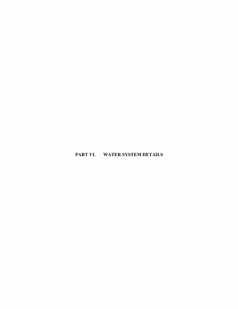
PART VI. WATER SYSTEM DETAILS


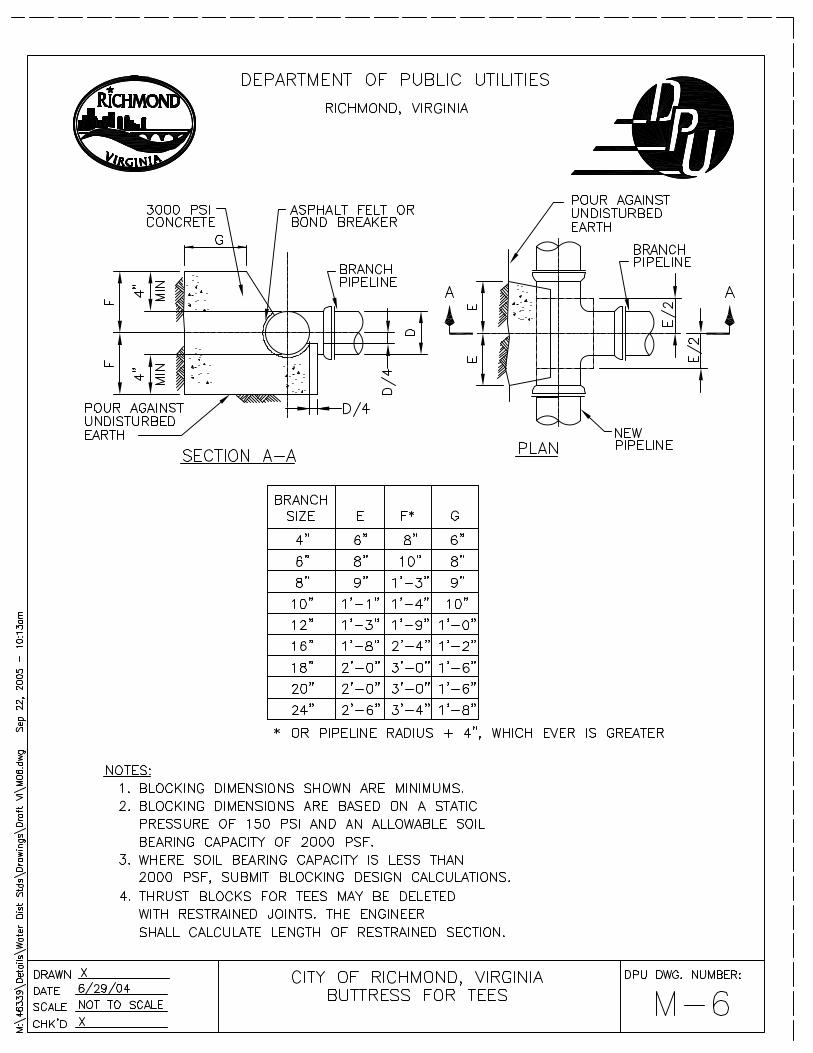


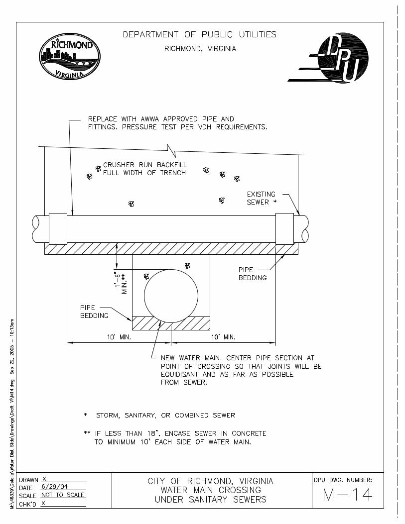


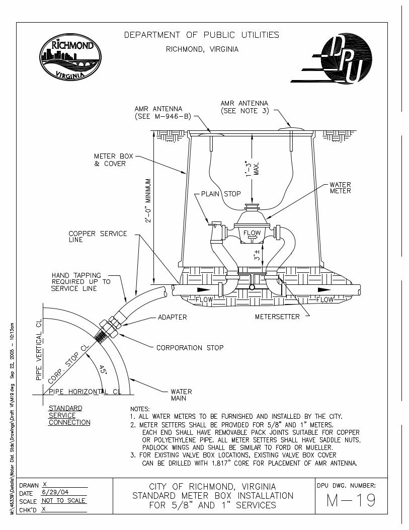


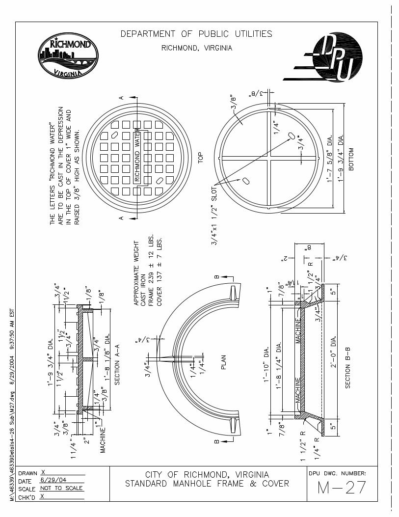

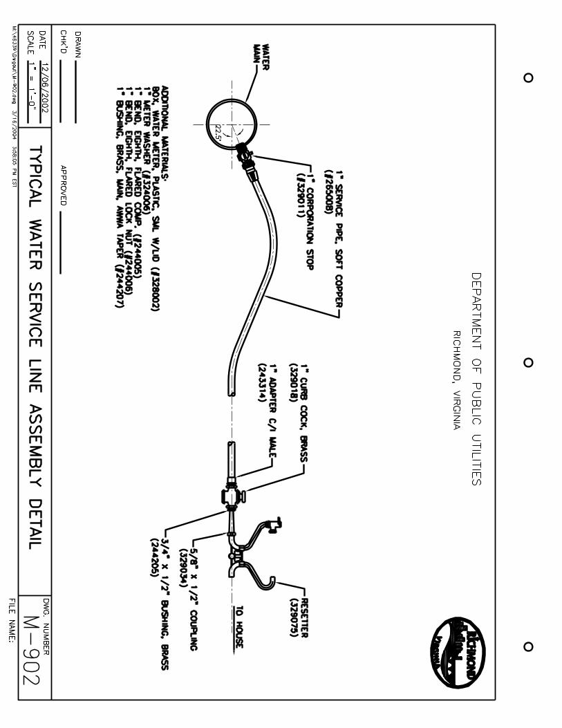
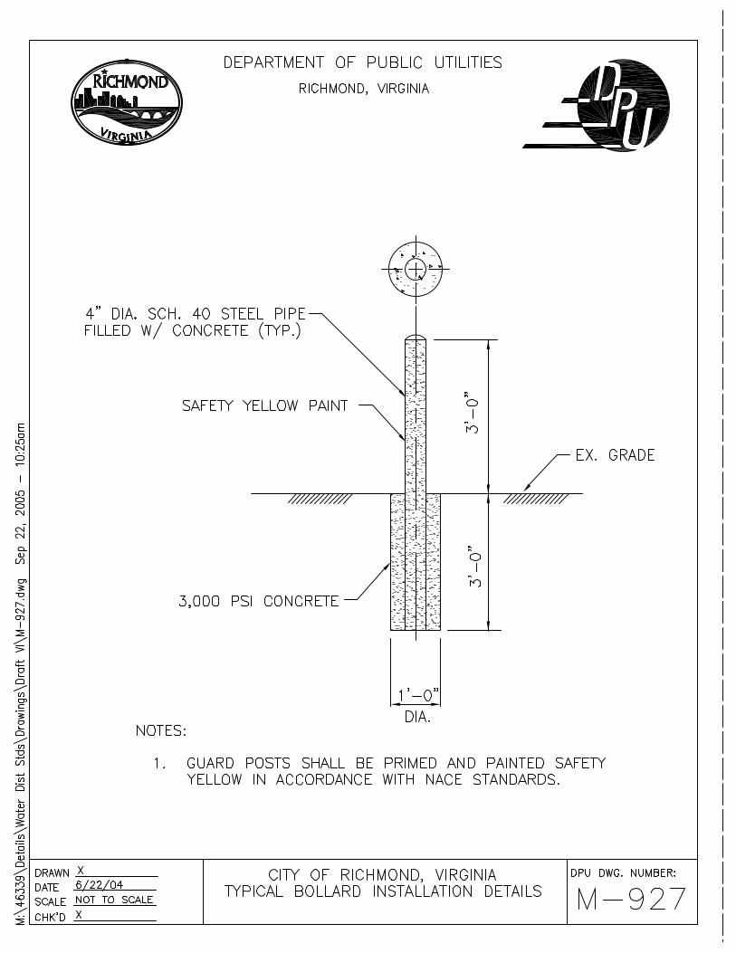


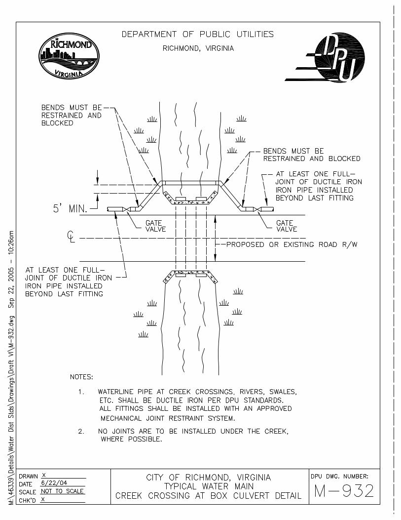


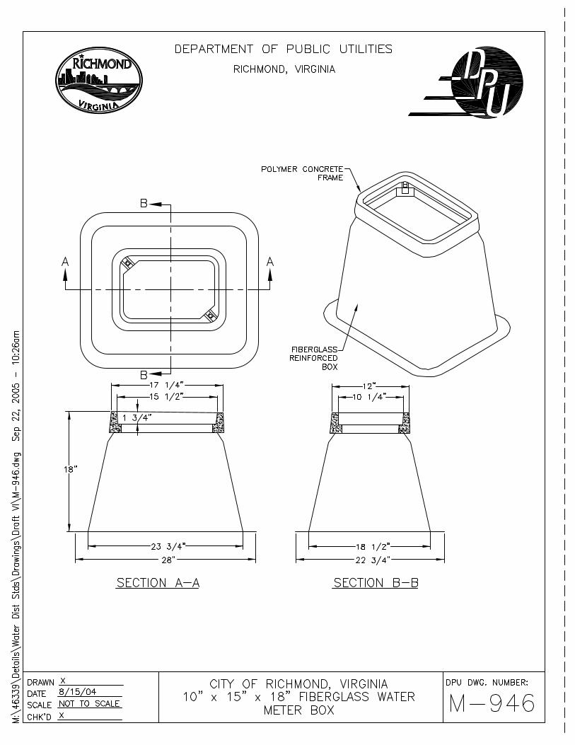


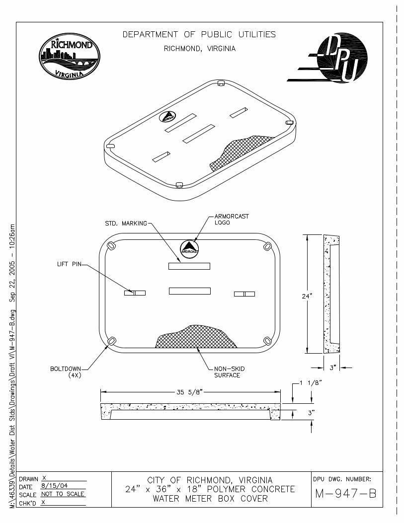
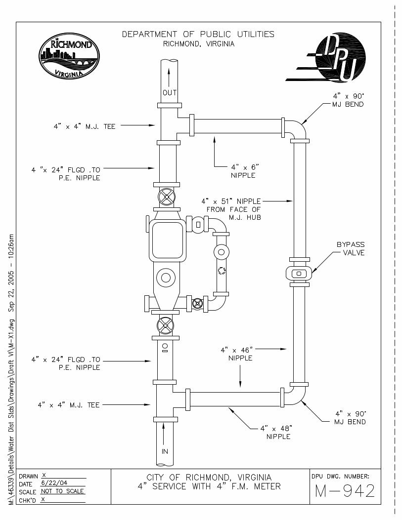


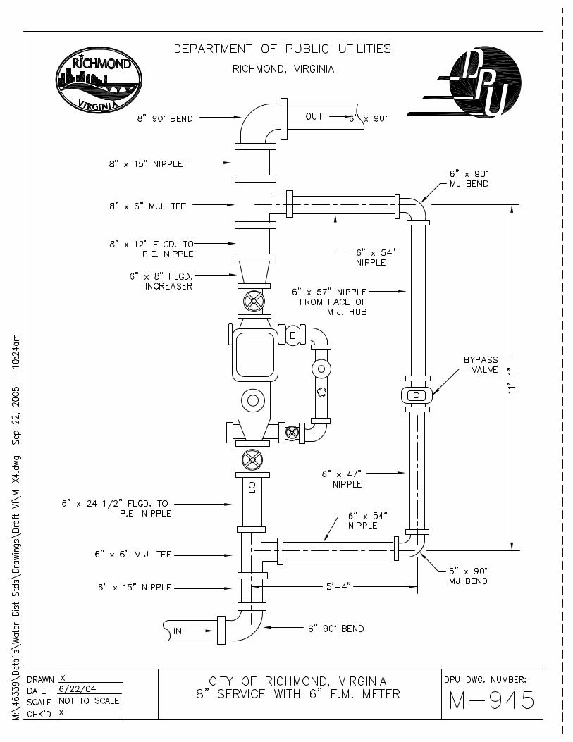
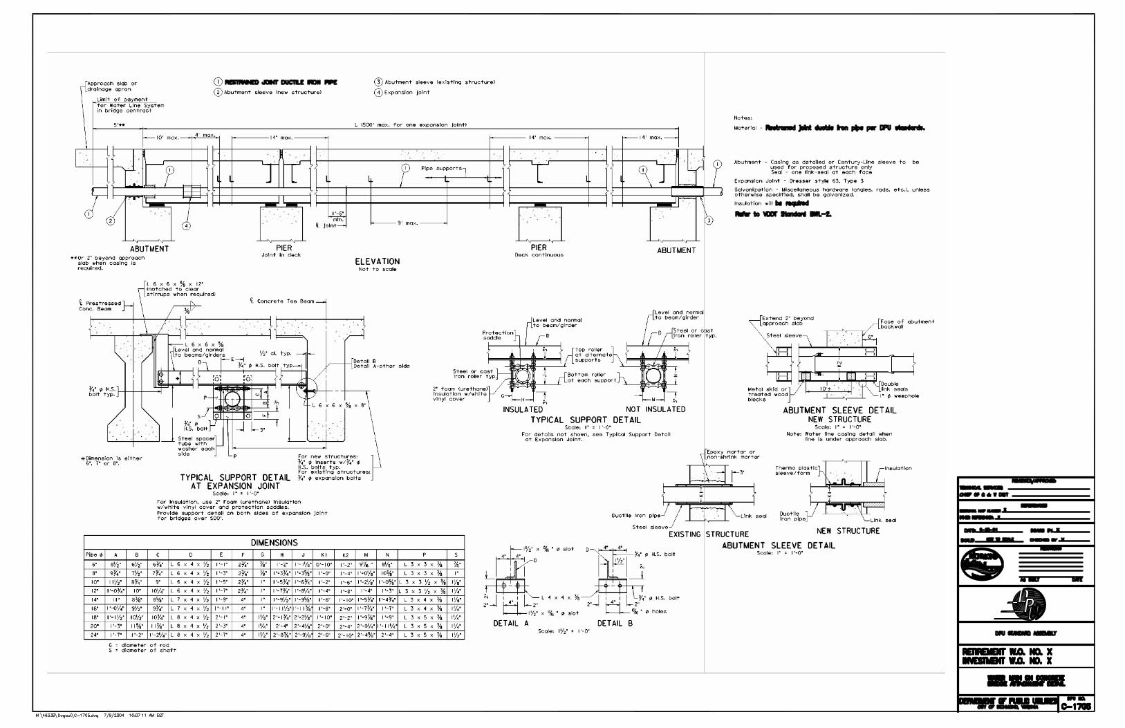
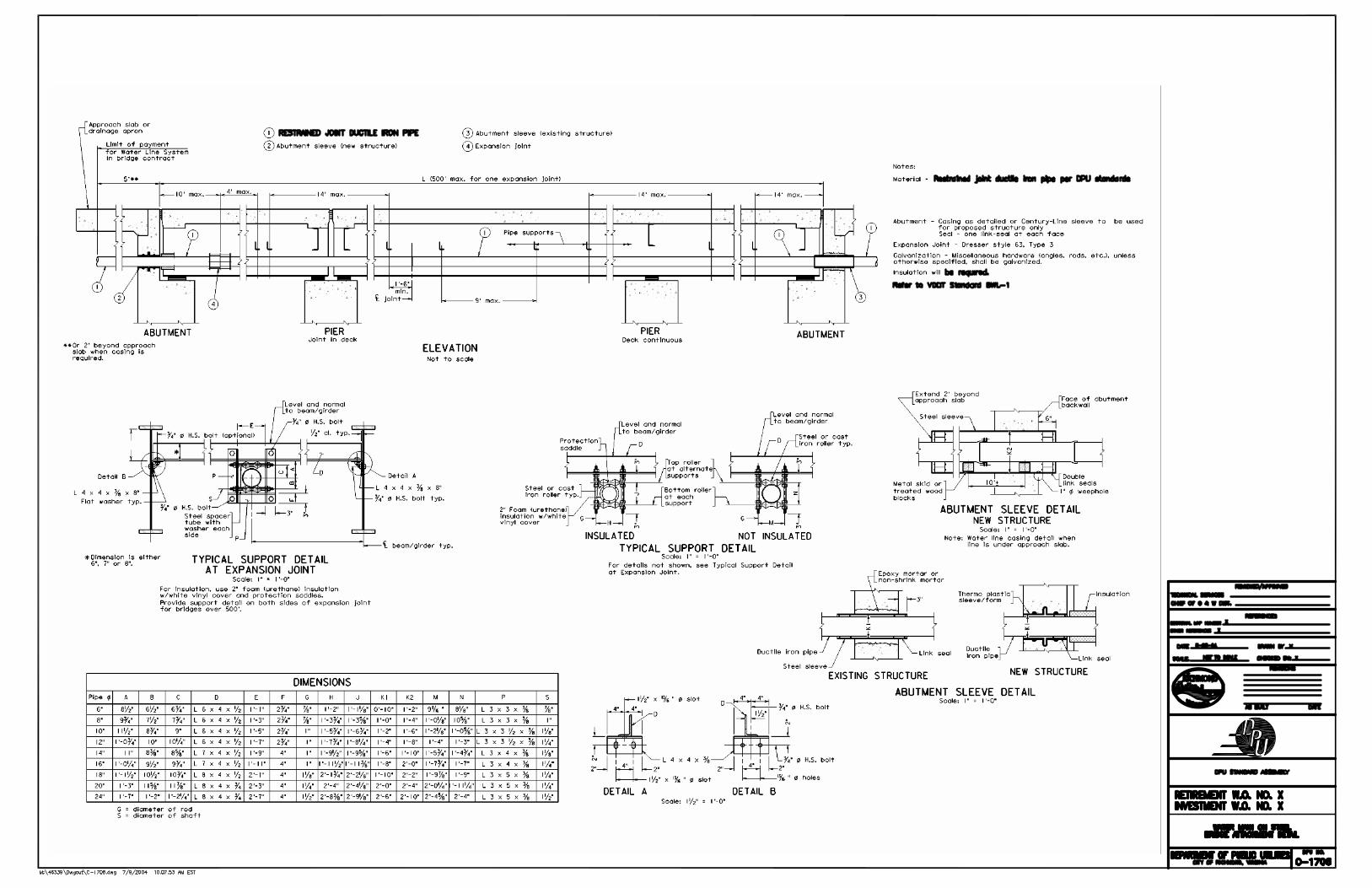

PART VII. STANDARD METER DETAILS AND PARTS LIST


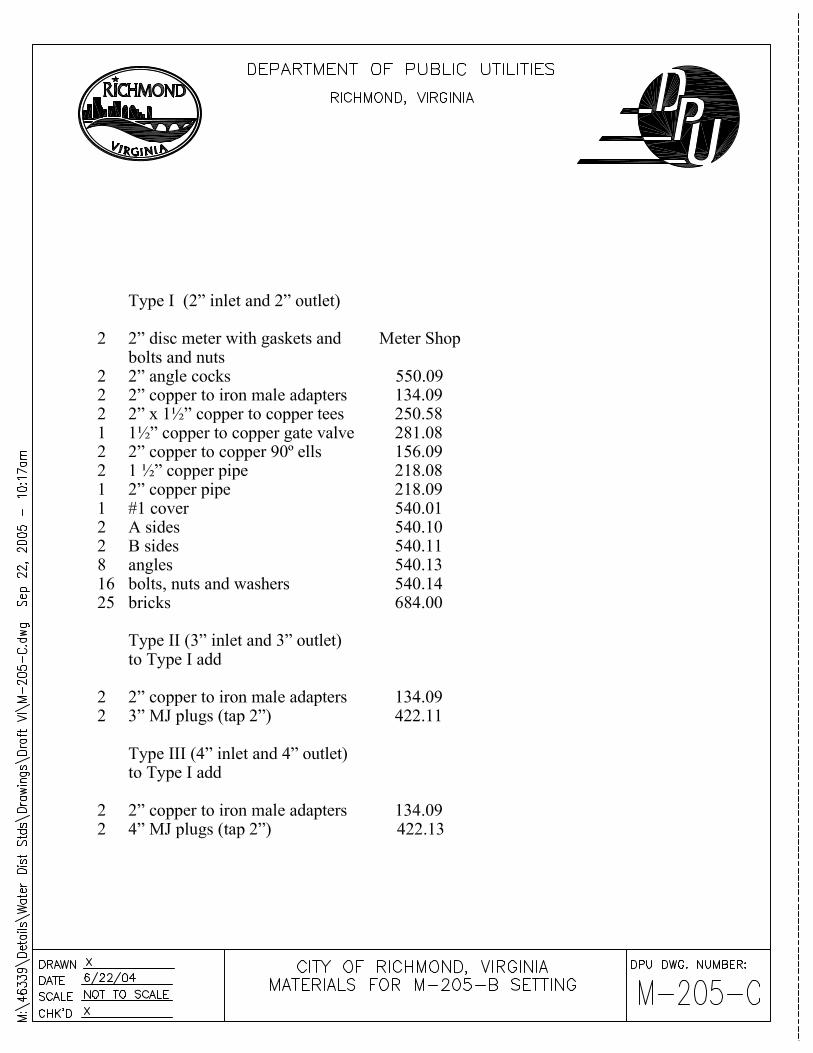


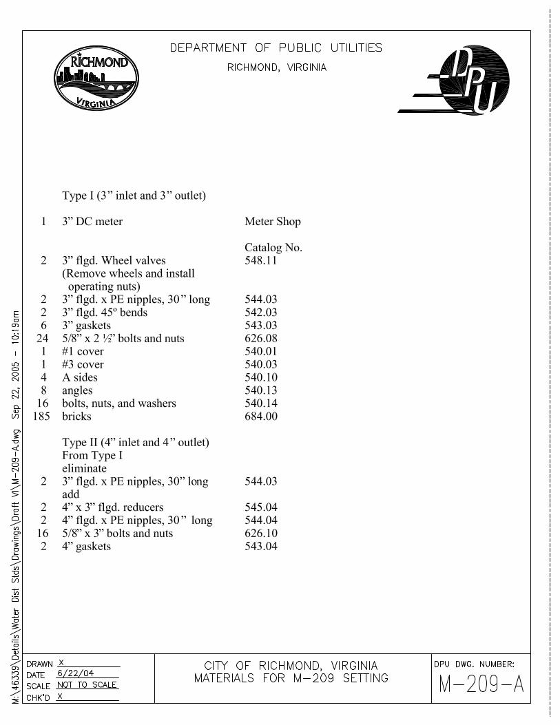


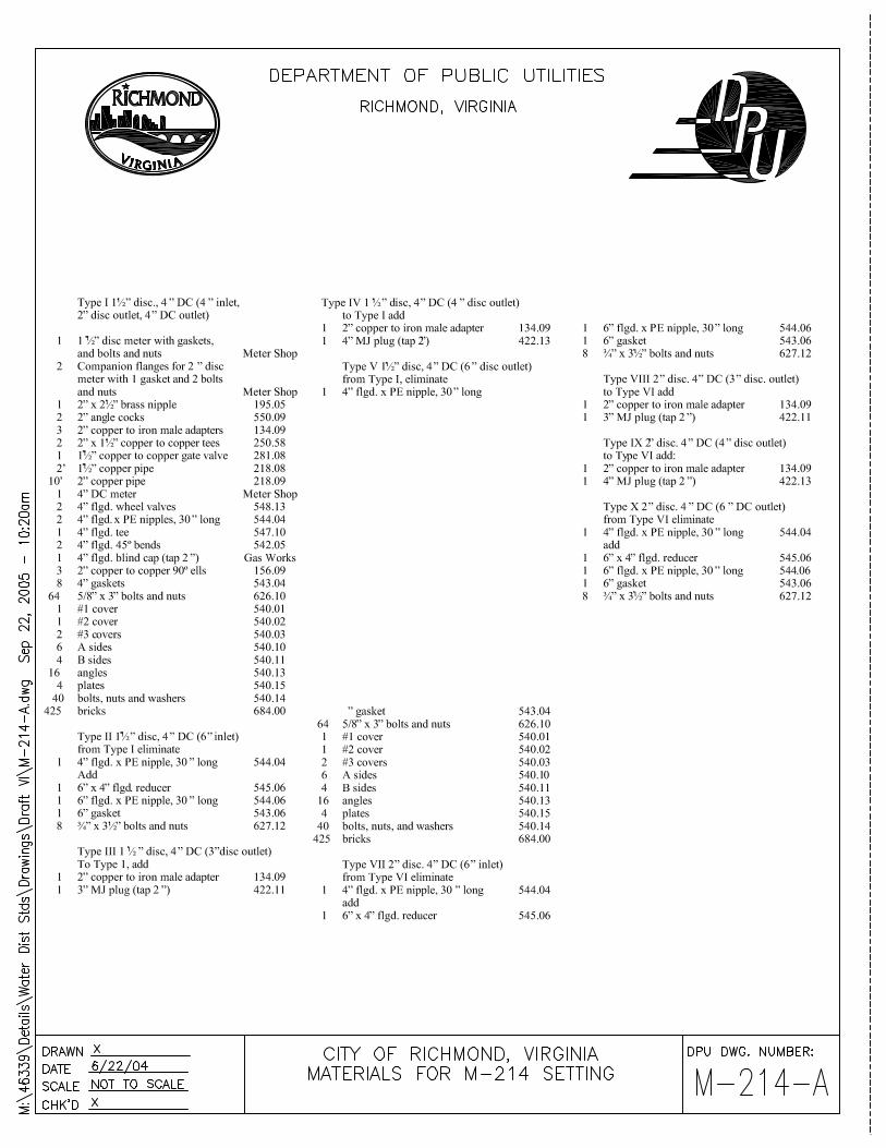
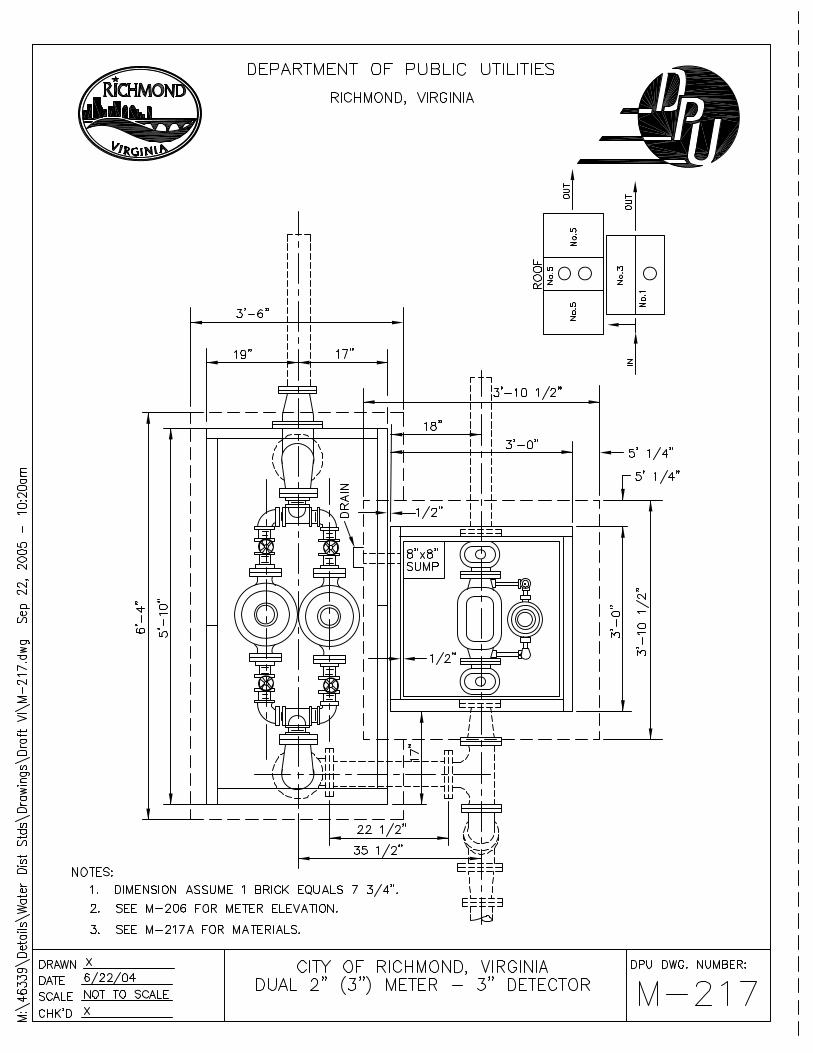


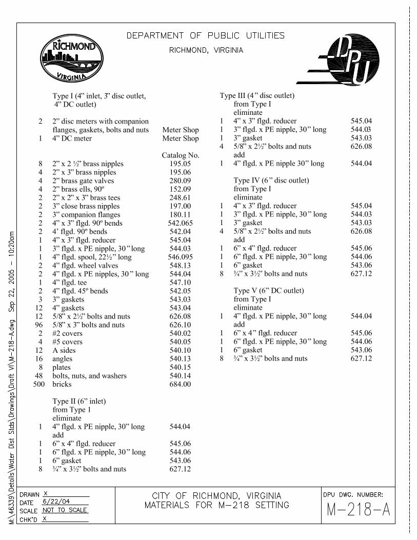
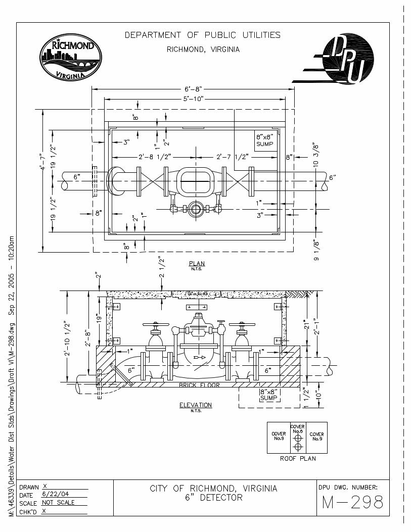


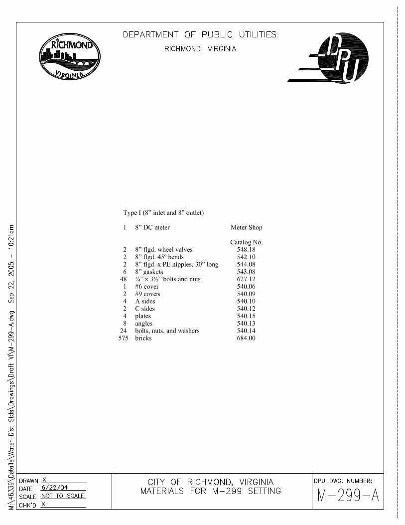

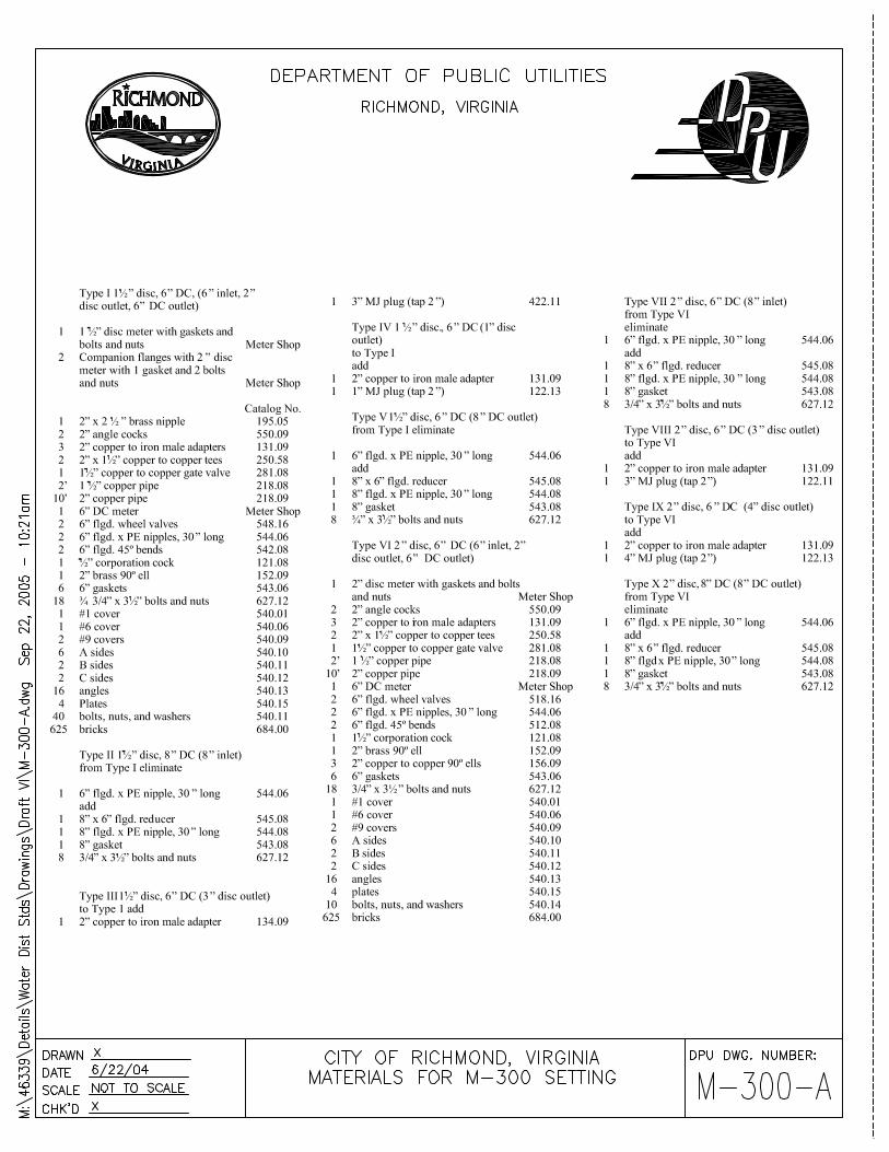


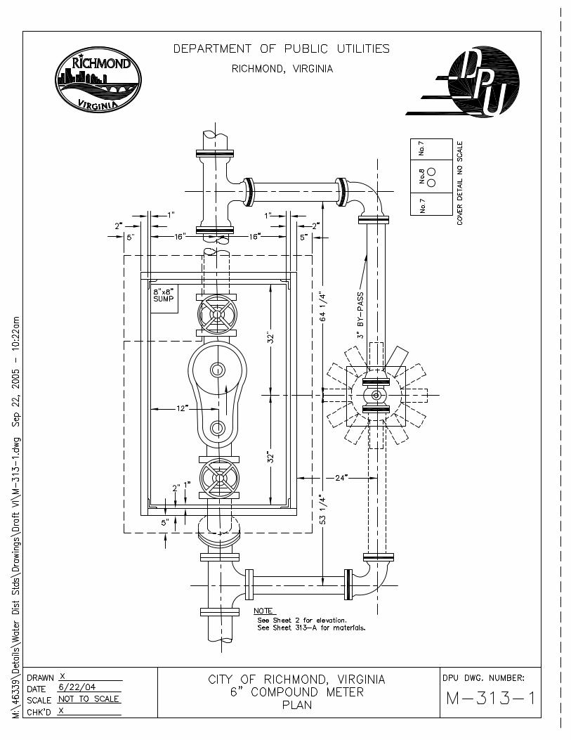

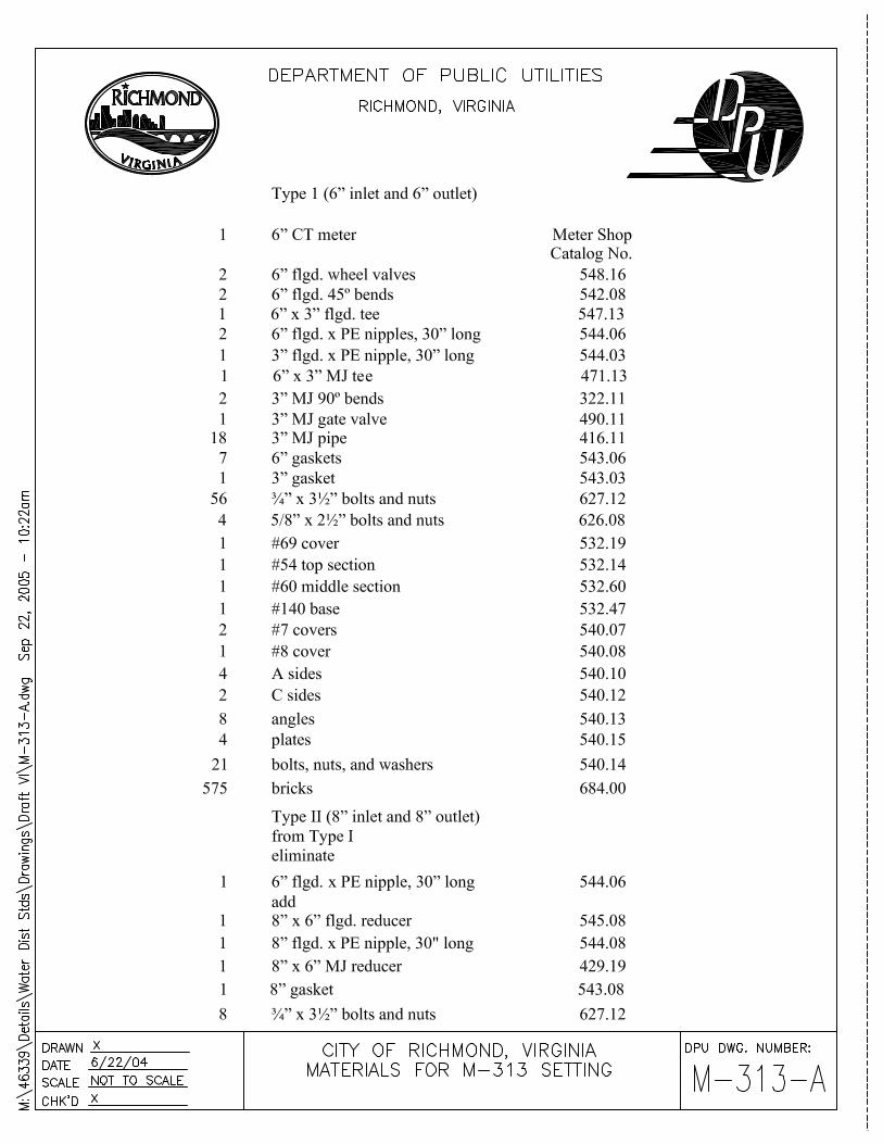

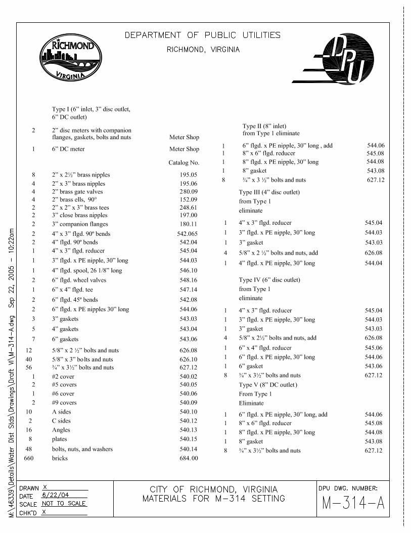


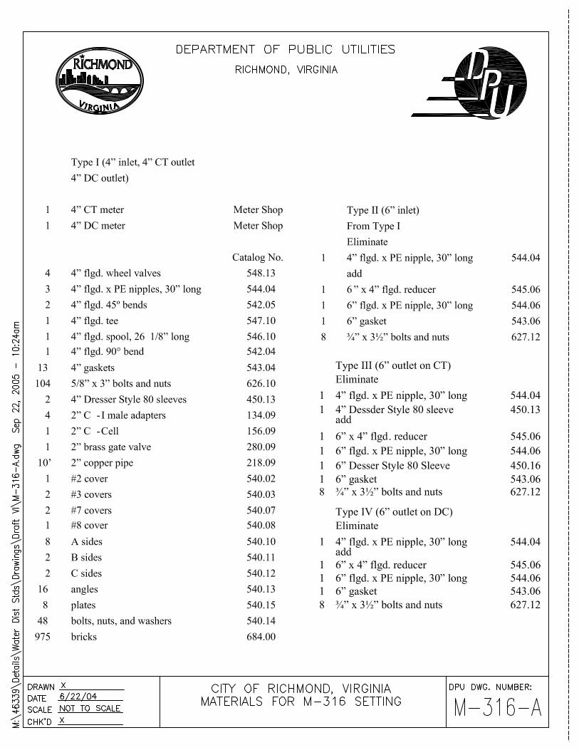

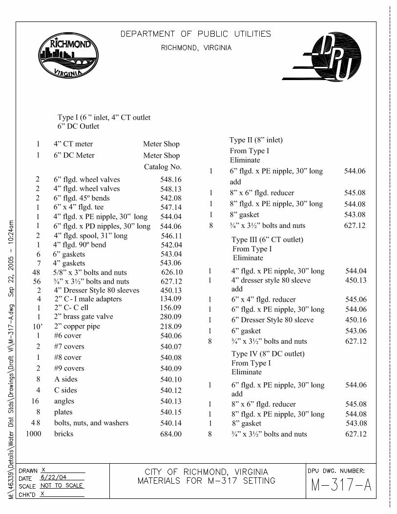


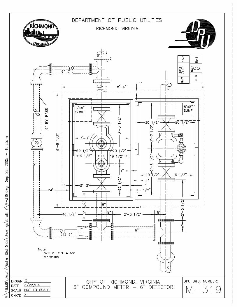
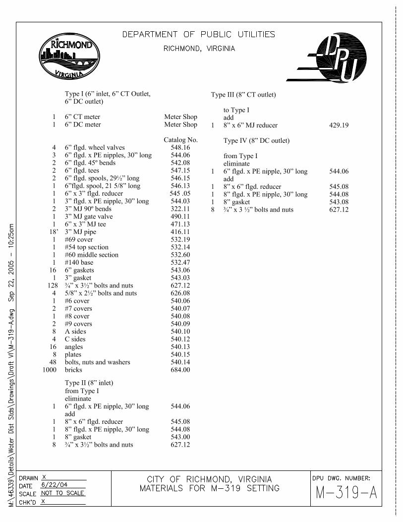

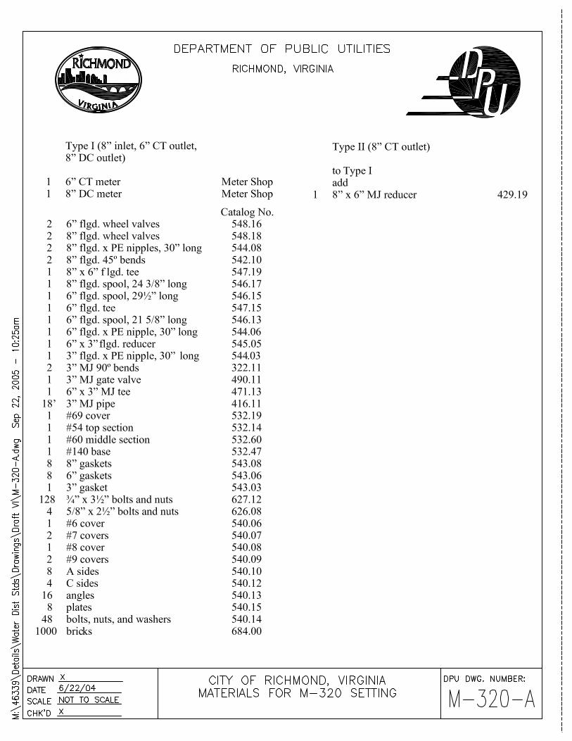

PART VIII. APPENDICES

APPENDIX A
CITY CODE QUICK REFERENCE SHEET

CC-1
City Code Quick Reference Sheet Situation: City Code Reference: Mains & services installed in easements Sec 106-34, 106-90, 106-249
Who shall pay for water main installation Sec 106-248, 106-281
Who is payment made to for main and service installation Sec 106-342, 106-343, 106-344
What must I do in order to apply for a main extension Sec 106-336, 106-338
Why does my fire line require a water meter Sec 106-350, 106-414
Why should I pay to have the City inspect the water main installation
Sec 106-84
Why do I need to have a water meter Sec 106-350
What do I do if I want to increase/decrease the size of my water service meter
Sec 106-349, 106-351
What the City’s requirements for meter vault construction Sec 106-352
If there is no space available for a meter outside of my property, where will it go
Sec 106-353
Who must fill out the water meter application for my building
Sec 106-92, 106-336, 106-338
Why do I need to have backflow prevention on my water service/s to my property
Sec 106-311, 106-347
If I need to have my water service relocated, will I be required to pay for this
Sec 106-354
I live in the County and would like to have City water, what must I do to obtain this
Sec 106-253, 106-284
CC-2
Sec. 106-90. Public utilities, etc., on county land. Whenever any property situated in the City contiguous to its corporate limits is used for dwelling purposes or is restricted in its use by the City's comprehensive zoning plan for such purposes, and any property contiguous thereto situated in a county is permitted to be used for commercial, shopping, business or industrial purposes:
1) No sewer, gas or water or electric wire, pole or conduit shall be installed, maintained or operated by the City, nor shall sewage disposal, gas, water or electric service be furnished by the City, to or for such property situated in the county, or otherwise in connection with the use thereof, unless authorized by the City Council by ordinance, anything in this Code or other provision of law to the contrary notwithstanding.
2) No street, alley, road or other means of access to or from the property situated in
the county shall be opened, constructed or maintained by the City through any property in the City, unless authorized by the City Council by ordinance.
3) No land or easement in lands shall be acquired or the dedication thereof shall be
accepted by the City, either independently or as a part of a plan of subdivision of land, or otherwise, for the purpose of providing such services or means of access, unless authorized by the City Council by ordinance, anything in this Code or other provision of law to the contrary notwithstanding.
4) Whenever property in a county is separated from property in the City by a street,
alley, road or other means of access, such property shall be deemed to be contiguous for the purposes of this section.
Nothing contained in this section shall be construed to affect any existing contract or deed relating to the subject matter of the provisions of Subsections (1), (2) and (3) of this section. (Code 1985, § 30-2) Charter references: Powers of City relating to public works and utilities, § 2.03.

CC-3
Sec. 106-249. Determination of time for construction of mains; size and character of mains. The Director shall determine when water mains shall be constructed in streets or easements and the character and size of the mains. Mains shall be installed in easements only when, in the opinion of the Director, there is no other practical method of conveying water from facilities in public streets, alleys and other public ways or places. (Code 1985, § 30-46) Sec. 106-342. Costs of original connections and maintenance In making installations of water service connections in the City, the Director shall furnish all necessary materials and have the service installed, the cost of which shall be paid as follows:
1) The entire cost of all original water service connections including restoration of the paving and meters shall be paid for by the owner or occupant of the premises to be served.
2) The entire cost of maintaining existing water service connections and meters,
except as otherwise provided in Section 29-60, shall be paid by the City; provided, that whenever an existing water service connection is replaced at the request of the owner with one of greater capacity, the entire cost of such service connection and restoration of the paving shall be paid for by the owner or occupant of the premises served. The Director shall determine the cost for the replacement using the procedures specified in the rules and regulations adopted pursuant to Section 29-48. The customer shall pay for the cost of meters as required in Section 29-73.
(Code 1985, § 30-61; Ord. No. 97-96-164, § 1, 5-27-97)

CC-4
Sec. 106-343. Estimate of installation cost of connections; fees. Upon receipt of an application for a water service connection made in the manner specified in Section 29-67 and for which the owner or occupant of premises to be served is required to pay pursuant to Section 29-61 or otherwise, the Director shall establish the fee for installing the service connection using the construction schedule developed by the Director. The Director annually shall determine construction costs and annually shall develop and publish a schedule of fees pursuant to the procedures set forth in Section 29-48. The applicant shall pay the fee to the City. The Director may receive installment payments as outlined in the rules and regulations adopted pursuant to Section 29-48. (Code 1985, § 30-62; Ord. No. 97-96-164, § 1, 5-27-97) Sec. 106-344. Special conditions pertaining to developers.
a) The provisions of Section 29-62 shall apply to all existing and new buildings or structures that are to be served by existing water mains and shall apply to existing buildings or structures to be served by new water mains constructed with City funds.
b) The fee for connections to water mains constructed by developers or when the
developer reimburses the City for the total cost of the water mains within the development shall be the average cost for services installed under similar conditions as estimated by the Director for the labor, materials, equipment and supervision required to provide the service. This special connection fee shall not apply unless the connection is paid for prior to the surfacing or resurfacing of the street or easement in which the water main is installed. The developer may, if the developer chooses, pay only the cost outlined above less the cost of the meter. The meter shall be paid for when it is needed at the average cost for meters installed under similar conditions as estimated by the Director for the labor, materials, equipment and supervision required.
(Code 1985, § 30-63)

CC-5
Sec. 106-346. Size, character and arrangement of connections. The Director shall determine the size, character and the arrangement of all gas or water service connections installed within or without the City. (Code 1985, § 30-65) Sec. 106-347. Prevention of cross-connection or backflow. (a) The following words, terms and phrases, when used in this section, shall have the meanings ascribed to them in this subsection, except where the context clearly indicates a different meaning:
Backflow means the flow of water or other liquids, materials or substances into the pipes or into other facilities of the city’s water distribution system from any source other than the city’s normal source of water, meeting standards for use and consumption of water, or from any alternate source of water meeting such standards which might be utilized by the city for the purpose of supplying water to the customers served by the water distribution system of the city. Cross-connection means any connection or structural arrangement, direct or indirect, to the city's water distribution system whereby a backflow can occur. (b) To protect and insure that the water distribution system of the city is pure and safe for public consumption as mandated by applicable state law and regulations, if any service connection for the supply of water to property from the water distribution system of the city may cause or result in a cross-connection to the city's water distribution system, the director is authorized to require the abatement or control of such cross-connection or possible cross-connection in accordance with regulations to be promulgated by the director authorized in this section. (c) The director shall promulgate rules and regulations pursuant to section 106-32 in order to prevent and control cross-connection and backflow. Such rules and regulations shall be consistent with applicable state law and regulations and may provide for the termination of water service where necessary to protect the health of the citizens or where an owner or occupant of premises refuses to comply with the regulations. (Code 1985, § 30-65.5)

CC-6
Sec. 106-338. Application for service connection. Application for water service connections shall be made to the director on forms provided by owners of premises to be served or by the occupants thereof through licensed plumbers, unless otherwise authorized in chapter 14 pertaining to buildings and building regulations and no water service shall be connected until the director shall approve such application. (Code 1985, § 30-66) Sec. 106-349. Cost, title and maintenance of meters. Service meters used for an original or enlargement of a water service connection shall be paid for by the owner or occupant of the premises served. Title to all service meters heretofore or hereafter installed shall remain or vest in the City. Credit for existing meters shall be given in accordance with Section 29-75. The City shall maintain, repair or replace existing service meters at its cost and expense, except as otherwise provided in Section 29-60. (Code 1985, § 30-72) Sec. 106-350. Meters required for each service. For each separate water service connection, the City shall furnish, install at the expense of the owner and maintain at the expense of the City a service meter to measure the quantity of water used, consumed or wasted on the premises served; except, that water connections used exclusively for private fire protection shall be installed in accordance with Section 29-114. (Code 1985, § 30-73)
CC-7
Sec. 106-351. Credit for existing meter or substitution. Credit for existing service meters allowed the applicant shall be under the following conditions:
1. When a service smaller than three-quarter inch nominal diameter is replaced with one of three-quarter inch nominal diameter in the same location, the City shall bear the entire cost.
2. When a service is replaced in a new location with a larger pipe but using the same
size meter, or when a service of three-quarter inch nominal diameter or larger is replaced in the same location with a larger pipe but using the same size meter, the customer shall pay the prevailing standard charge for a water service connection, less the current cost of a new meter of the same size.
3. When a meter is enlarged in the same location without change of pipe size, the
customer shall pay the City the difference in the current cost of the two (2) meters and all labor and construction costs necessary to permit the use of the larger size meter.
4. When a meter is enlarged in a new location without change of pipe size, or when
both the meter and pipe size are enlarged either in the same or a new location, the customer shall pay the prevailing standard charge for a water service connection, less the current cost of a new meter of the original size.
5. When a meter is replaced with one of less cost to the City, no refund shall be
made.
6. If a new service replaces two (2) or more old services, credit shall be allowed for one of the old meters, but in no event shall the credit for the old meter exceed the cost of the new meter.
(Code 1985, § 30-74)

CC-8
Sec. 106-352. Meter boxes required; cost of constructing and maintaining boxes. All meters installed outside of buildings, whether on private or public property, shall be installed in boxes or vaults of such size and materials as the Director shall prescribe, and the cost of constructing or installing such boxes or vaults shall be paid by the owner or occupant of the premises served. If such boxes or vaults are located on private property, the cost of their maintenance shall be at the expense of the owner or occupant of the premises served. (Code 1985, § 30-75) Sec. 106-353. Inside Meter location. On premises where no place for any outside meter is available, the owner or occupant of such premises shall provide, without cost to the City, a place within the building for the water service meter or detecting device, which shall be contiguous or adjacent to the entrance of the service connection upon the premises and shall be satisfactory to and approved by the Director. (Code 1985, § 30-76) Sec. 106-354. Meter Relocation. Upon the written request of the owner or occupant to move a water service meter or detecting device from one place to another, or should a change in the use of a premises or structural alteration therein render a place in which such meter or device is installed to be unsatisfactory to the Director, the water service meter or detecting device shall be moved to another place that is satisfactory to the Director, and the entire cost of providing such other place and the moving and installation of the meter or device therein and the changes in pipes occasioned thereby shall be paid by the owner or occupant of the premises served. (Code 1985, § 30-77)
CC-9
Sec. 106-414. Service connections. Service connections used exclusively for private fire protection within or without the City shall be equipped with devices approved by the Director located in the service lines, which will indicate the use of any water passing through such service lines. These devices shall be furnished and installed by the City at the cost and expense of the owner or occupants of premises served. (Code 1985, § 30-114)

APPENDIX B
STANDARD FORMS

Release of Assets to the City of Richmond-DPU 1 of 4
City of Richmond, Dept. of Public Utilities, MIS 400 Jefferson Davis Hwy Richmond, VA 23224 Contractor Release of Asset – Requirements The following requirements are intended to provide the Maintenance Organization with all of the necessary documents, information, drawings, O&M Manuals, warranty information, spare parts and any special tools required to perform maintenance on an asset turned over from a contractor to the Department of Public Utilities. Here are the requirements that must be included but not limited to this list. Additional information that is available should be included:
A. Shop Drawings: The CONTRACTOR shall submit complete shop drawings for each piece of equipment turned over. Such shop drawings shall include all electrical, mechanical and instrumentation requirements.
B. O & M Manuals: The CONTRACTOR shall furnish to the Department 6 copies of
complete operating and maintenance instructions for each piece of equipment released. The data shall consist of catalogs, brochures, bulletins, charts, schedules, material safety data sheets, equipment numbers, nameplate data, wiring diagrams, and assembly drawings which shall describe location, operation, maintenance, operating weight, vendor lists, and other necessary information for the Department to establish a complete maintenance program. The CONTRACTOR shall also furnish detailed instructions for start-up, normal operation, shutdown procedures, and control techniques; and a guide to troubleshooting the system including manufacturer’s written instructions.
C. Special Tools: The CONTRACTOR shall supply one complete set of special
wrenches or other special tools necessary for the assembly, adjustment, and dismantling of the equipment. All tools shall be of best quality and furnished in labeled toolboxes of suitable design.
D. Lubricants: The CONTRACTOR shall furnish specifications for the
manufacturer recommended lubricants. This should include any lubrication charts applicable.
E. Spare Parts Listing: The CONTRACTOR shall furnish a complete spare parts
listing as recommended by the manufacturer, such as bearings, drive belts, seals, washers, rings, and any other parts subject to wear or frequent replacement.
F. Asset Information: Complete description of the asset is necessary in
order to include it in the City of Richmond-DPU database. The required data is outlined in the attached spreadsheet (Attachment 1). This is available electronically, which offers an imbedded description of most of the cells.

Release of Assets to the City of Richmond-DPU 2 of 4
G. Spare Parts: The Contractor shall clearly identify all spare parts released with the asset. All spare parts shall be properly labeled and identified with the name and number of the equipment to which they belong. The minimum required information is outlined in the attached spreadsheet (Attachment II). This is available as an electronic spreadsheet for your use as required.
H. Warranty Information: The Contractor shall furnish all Warranty
information pertaining to the released piece of equipment. Including costs for extended warranties.
I. Service Provider(s): The Contractor shall furnish a list of all authorized
service providers for the piece of released equipment. This would include authorized providers of spare parts for the piece of equipment.
J. Digital Format: The CONTRACTOR shall furnish all information in both Hard
Copy as well as Digital Format. The City prefers PDF format for documents other than CADD drawings, which should be .dwg format.
K. Other Information:
a. Recommended maintenance products

Release of Assets to the City of Richmond-DPU 3 of 4
Attachment I
Asset Information Spreadsheet ADD A NEW ASSET DATA ENTRY FORM - SHORT FORM MAINSAVER Field
TAB FIELD NAME DATA TO BE ENTERED Lngth
Asset Asset No: 50
Asset Asset Type: 1
Asset Work Area: 2
Asset Cost Center: 50
Asset Location: 50
Asset Short Description: 30
Asset Parent ID: 50
Asset Asset Group Code: 15
Company Name Please provide the
Company Name and Phone Number that you would
purchase this Asset from.
Phone Number:
Reliability Manufacturer: 25
Reliability Model No: 50
Reliability Serial No: 50
Reliability Date Installed/Purchased
Financial Estimated Asset Life
Financial Warranty Expiration Date
Notes: 2000

Release of Assets to the City of Richmond-DPU 4 of 4
Attachment II
Part Information Spreadsheet
ADD A NEW PART DATA ENTRY FORM - SHORT FORM
Asset Number the part is associated with: > > > > > Field
FIELD NAME DATA TO BE ENTERED Lngth Req
Stock Number: We assign 25 x
Part Description: 80 x
Issue Unit Of Measure: 8 x
Recommended Supplier: 25 x
Supplier Part Number: 25
Manufacturer: 25
Mfg Part No: 25
Item Cost: 8
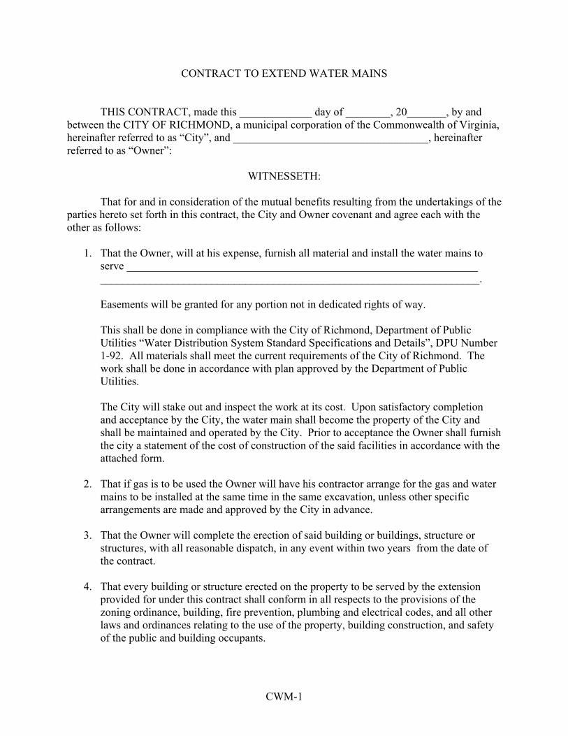
CWM-1
CONTRACT TO EXTEND WATER MAINS
THIS CONTRACT, made this _____________ day of ________, 20_______, by and between the CITY OF RICHMOND, a municipal corporation of the Commonwealth of Virginia, hereinafter referred to as “City”, and ___________________________________, hereinafter referred to as “Owner”:
WITNESSETH:
That for and in consideration of the mutual benefits resulting from the undertakings of the parties hereto set forth in this contract, the City and Owner covenant and agree each with the other as follows:
1. That the Owner, will at his expense, furnish all material and install the water mains to serve _______________________________________________________________ ____________________________________________________________________. Easements will be granted for any portion not in dedicated rights of way. This shall be done in compliance with the City of Richmond, Department of Public Utilities “Water Distribution System Standard Specifications and Details”, DPU Number 1-92. All materials shall meet the current requirements of the City of Richmond. The work shall be done in accordance with plan approved by the Department of Public Utilities. The City will stake out and inspect the work at its cost. Upon satisfactory completion and acceptance by the City, the water main shall become the property of the City and shall be maintained and operated by the City. Prior to acceptance the Owner shall furnish the city a statement of the cost of construction of the said facilities in accordance with the attached form.
2. That if gas is to be used the Owner will have his contractor arrange for the gas and water
mains to be installed at the same time in the same excavation, unless other specific arrangements are made and approved by the City in advance.
3. That the Owner will complete the erection of said building or buildings, structure or
structures, with all reasonable dispatch, in any event within two years from the date of the contract.
4. That every building or structure erected on the property to be served by the extension
provided for under this contract shall conform in all respects to the provisions of the zoning ordinance, building, fire prevention, plumbing and electrical codes, and all other laws and ordinances relating to the use of the property, building construction, and safety of the public and building occupants.

CWM-2
5. That the Owner will not assign this contract or any of the rights, benefits, privileges, duties or obligations enured, received, imposed or assumed under this contract.
IN WITNESS WHEREOF, The City has caused its name to be subscribed hereto by its Director of Public Utilities, and the Owner has hereto affixed his signature.
CITY OF RICHMOND BY:____________________ Director of Public Utilities PROPERTY OWNER BY:______________________ TITLE:____________________ APPROVED AS TO FORM: BY:_______________________ City Attorney
DE-1
Prepared by ______ Tax Parcel #
DEED OF EASEMENT
THIS DEED OF EASEMENT, made this ___ day of ______, 2003 between ________, a Virginia limited liability company, hereinafter referred to as “Grantors,” and the CITY OF RICHMOND, a municipal corporation of the Commonwealth of Virginia, hereinafter referred to as “Grantee”;
WITNESSETH
WHEREAS, Grantors are the owners of certain land wherein as easement for water and sewer thereto is to be granted, pursuant to the provisions of Section 26-42 of the 2001 Richmond City Code, and are willing to grant the Grantee the said easement. NOW, THEREFORE, in consideration of the sum of One Dollar ($1.00) and other good and valuable consideration, receipt of which is hereby acknowledged, the Grantors do hereby give, grant and dedicate and convey to the Grantee, with General Warranty of Title, a perpetual easement in and across the land owned by the Grantors for the construction, reconstruction, maintenance, repair, and operation of water and sewer facilities, as shown as “16’ Sewer Easement”, “Variable Width Sewer Easement” and “Variable Water Easement” on the plat prepared by _______, entitled, “Utility Easements for _________,” marked “Job No.____”, a copy of which is attached hereto and made a part of this deed of easement, being a portion of the same real estate conveyed to _________ by deed recorded in the Clerk’s office of the Circuit Court of Richmond as instrument #__________. The Grantee hereby convenants and agrees with the Grantors that the Grantee will restore or replace the land and the surface thereof with the boundaries of the easement to its original condition as far as practicable upon completion of the construction, reconstruction, maintenance or repair of said water or sewer facilities. IN WITNESS WHEREOF, the Grantors have hereunto affixed their signatures and seals as of the day and year first hereinabove written. ____________________ By: _______________________

DE-2
ATTEST: _____________ STATE OF VIRGINIA CITY OF RICHMOND, to-wit: I, _______________, Notary Public in and for the City and State aforesaid, do hereby certify that ______, whose names are signed to the foregoing deed of easement, bearing date ___ day of ____, 200__, personally appeared before me in my City and State aforesaid and acknowledged the same to be their act and deed. Given under my hand this ______ day of _____________, 200___. _______________________________ Notary Public My Commission Expires: _______________ This foregoing deed easement from ____________________ is hereby accepted the ___ day _______________, 200__, pursuant to authority granted by Section 8-22 of the 2001 Richmond City Code. CITY OF RICHMOND By:
________________________ Chief Administrative Officer Approved as to Form: _____________________ Assistant City Attorney

CITY OF RICHMOND DEARTMENT OF PUBLIC UTILITIES
REVIEW CHECKLIST FOR WATER PLANS
Project Title ___ 1. Virginia Registered engineer’s stamp, signature and date. ___ 2. Preliminary Engineering report including a System Layout Plan has been submitted. ___ 3. Water system is designed to provide adequate domestic service and fire protection to
owner’s property. ____ diameter line is required to adequately serve this project in accordance with City Standards.
a. Average Domestic Design Flow ______________ b. Per hour Domestic Flow ______________ c. Design Fire Flow ______________ d. Total Design Peak Flow ______________ e. Residual Pressure at Total Design Peak Flow (last hydrant) ______________ ___ 4. Information Sheet for Preparation of water Agreement has been submitted. ___ 5. Plan and profile sheets are on 24” x 36” paper. Drawing organization and format comply
with City DPU Standards. ___ 6. A Cover sheet is provided which includes the Owner/Developer name and address, project
vicinity map, and Standard Water and Sewer Notes. ___ 7. Domestic water meter calculations are shown on plans where applicable with A.W.W.A.
Manual M-22. ___ 8. I.S.O. Fire Flow computations are shown on plans (where applicable). ___ 9. All water mains 6-inches and larger are profiled. Where water mains of any size cross other
utilities, these crossings are profiled, and the means for crossing and resolving any conflicts are clearly shown.
___ 10. Any and all existing sewer and water connections to the property are shown on plans. ___ 11. All off-site easements necessary for the completion of this project have been acquired,
recorded and their Deed Book and Page references are shown o the plans. ___ 12. A list of the Appropriate material Quantities to be used and the latest material Notes are
shown on the plans. ___ 13. A Backflow Prevention Device is provided on domestic and fire service connections in
accordance with Part II, Article 3 of the Commonwealth of Virginia, State Board of Health Water works Regulations and the Cross Connection Control and backflow Prevention Program.
___ 14. Plans comply with all applicable Local, State and Federal regulations including City and State erosion control and application has been made for all required permits.
I have reviewed this Checklist for accuracy and hereby certify that the water and/or sewer plans as submitted have been designed in accord with the latest City Standards, Waterworks Regulations and Sewerage Regulations (whichever is more restrictive). The plans have been reviewed for completeness and accuracy and are herewith submitted for approval. Signature Certificate Number Name Typed or Printed Date
RC-1

City of Richmond
Department of Public UtilitiesRichmond, Virginia 23224