Embed Size (px)
Citation preview
78 The Open Mechanical Engineering Journal, 2011, 5, 78-86
1874-155X/11 2011 Bentham Open
Open Access
Numerical Simulation and Analysis on Jet Characteristics of Combined Plasma Arc
Jianbing Meng* and Xiaojuan Dong
Shandong Provincial Key Laboratory of Precision Manufacturing and Non-traditional Machining, Shandong University of Technology, Zibo 255049, China
Abstract: A three-dimensional axisymmetric mathematical model, including the influence of the swirl exiting in the plasma torch, was developed to describe the heat transfer and fluid flow within a combined plasma arc. In the model, a mapping method and a meshing method of variable step-size were adopted to mesh the calculation domain and to improve the results precision. To overcome a problem from a coexistence of non-transferred arc and transfer arc and a complicated interaction between electric, magnetic, heat flow and fluid flow phenomena in the combined plasma arc, a sequential coupling method and a physical environment approach were introduced into the finite element analysis on jet characteristics of the combined plasma arc. Furthermore, the jet characteristics of combined plasma arc such as temperature, velocity, current density and electromagnetic force were studied; the effects of working current, gas flow and the distance from the nozzle outlet to the anode on the distributions of temperature, velocity and current density were also revealed. Compared with the collection and diagnosis on the combined plasma arc by CCD, the results show that the simulated value appears to be in good agreement with measured value, and the temperature of combined plasma arc is much dependent on the working current, while is less sensitive to the argon flow rate and the distance from the nozzle outlet to the workpiece anode.
Keywords: Combined plasma arc, jet characteristics, numerical simulation, plasma diagnosis.
1. INTRODUCTION
Plasma arc has generally been applied to material pro-cessing such as plasma welding, plasma cutting, plasma spraying, etc. Its jet characteristic has a crucial and direct influence on above processing quality. However, the genera-tion of plasma arc involves complex physical phenomena, such as electromagnetic, heat flow and fluid flow, etc. Furthermore, the behavior of the coupling between these physical phenomena makes it quite difficult to grasp the distributions of temperature, velocity and current density of plasma arc with experimental methods. Aimed at above problem, numerical simulation method has been applied to plasma arc and it is proved feasible by some investigations. Westhoff and Szekely [1] made a numerical analysis of fluid, heat flow and electromagnetic phenomena in a non trans-ferred arc plasma torch. Though provided an important finding that the electromagnetic forces may markedly modify the velocity profiles and may significantly affect the swirl of the plasma, they assumed the cathode tip as flat rather than pointed. Bauchire et al. [2] modeled a DC non-transferred plasma arc both in laminar and turbulent flow and found the result of the laminar flow model was more agreement with experimental measurements, while current density distribution was assumed when electromagnetic field being analyzed. Seungho Paik et al. [3] also made a numerical analysis of non transferred plasma arc with the Steenbeck theory, and investigated the effect of arc root
*Address correspondence to this author at the School of Mechanical Engineering, Shandong University of Technology, Zibo 255049, China; Tel: +86-533-2785909 (Office), +86-13589488665 (Mobile); E-mails: [email protected], [email protected]
position on the temperature and fluid flow of DC non-transferred plasma torch. In addition, Ushio et al. [4,5] made a numerical simulation on the distribution of velocity and temperature in the non-constricted transferred plasma based on continuous equation, momentum equations, energy equation and Maxwell equation. Lu et al. [6,7] established an integral mathematic model of fluid flow and heat transfer of GTAW transferred arc and weld pool, and analyzed the behavior of transferred arc and weld pool including arc temperature field and current density distribution with finite element method. Especially, Yin et al. [8] developed a two-dimensional mathematical model to research the behavior of the transferred argon plasma arc constricted by a torch. The model also took the plasma arc as laminar flow and included the torch region to consider the influence of cathode figure and the restricted role of the nozzle. Up to now, many studies on the jet characteristics of transferred plasma arc and non-transferred plasma arc have been published, however, little attentions are given to a numerical simulation of the combined plasma arc. Further-more, as an ideal heat source, combined plasma arc has been generally applied to precise welding and also involves complex physical phenomena. Therefore, it is necessary to make a numerical analysis on the combined plasma arc. Unfortunately, it is quite difficult to apply above methods to simulate the combined plasma arc, due to the coexistence of non-transferred arc and transfer arc and the more complica-ted coupling between electric, magnetic, heat flow and fluid flow phenomena in the combined plasma arc. In this paper, a three-dimensional axisymmetric mathematical model on the combined plasma arc is established according to the theories of magneto- hydrodynamics (MHD) and electromagnetics,

Jet Characteristics of Combined Plasma Arc The Open Mechanical Engineering Journal, 2011, Volume 5 79
and is solved with the finite element methods including a sequential coupling method and a physical environment approach. In this model, a conservation of azimuthal momentum is introduced to avoid the assumption of plasma flow independent of the swirl existing in combined plasma arc. A mapping method and a variable step-size meshing method are also adopted to improve the calculation preci-sion. Moreover, the distributions of the current density, electromagnetic force, temperature and velocity of combined plasma arc are described. The influence of processing para-meters, such as working current, argon flow rate and the distance from the nozzle outlet to the workpiece anode on above distributions are also investigated. As well as, the simulated results are compared with the measured values obtained from the collection and diagnosis on the combined plasma arc by CCD.
2. MODELING APPROACH
Calculation Domain
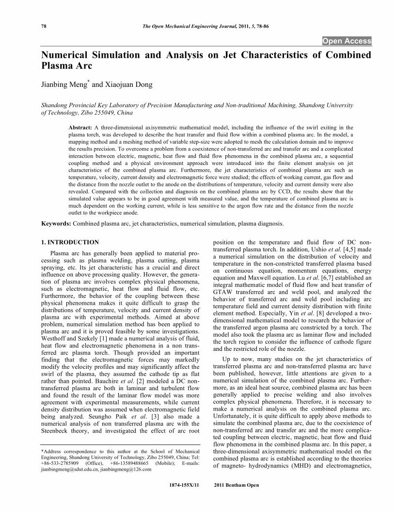
Fig. (1) presents a schematic sketch of a combined plasma arc. Firstly, the non-transferred arc between the tungsten cathode and the nozzle is be ignited, then the transferred arc between the tungsten cathode and anode workpiece is also ignited. Consequentially, the combined plasma arc will be generated. Being a main working arc, the transferred arc plays a key role in the combined plasma arc, and non transferred arc can remarkably improve the stability of the transferred arc. Wherefore, it can be seen that the combined plasma arc consists of a non-transferred arc and a transferred arc, and results in a complicated coupling bet-ween physical phenomena such as electricity, magnetism, heat and force, etc. In order to objectively simulate the generation of combined plasma arc as much as possible, and to ensure boundary conditions easily determined, the calcu-lation domain of the combined plasma arc is shown in Fig. (2). The whole calculation domain can be divided into the domain of electromagnetic field and the domain of flow field, as well as each domain is composed of a domain of non-transferred arc and a domain of non-transferred arc. The domain of ABCDEIJKLB is used for solving the electro-magnetic field in non-transferred arc, and the domain of AEFGHIJKLBCDE is used for solving the electromagnetic field in transferred arc. To avoid an assumption of the current density distribution on the cathode surface, the tungs-ten cathode ABCDE is included into above both calculation domains. In addition, the domain of BCDEFGHIJKLB is used for solving the fluid field in the combined plasma arc.
Tungsten cathode
Gas intlet
Nozzle
Plasma arc
Anode
Fig. (1). Schematic of the combined plasma arc.
In order to establish a mathematical model of the com-bined plasma arc and to simplify its calculation, the following assumptions have to be summarized as follows: 1. The plasma arc is assumed to be pure argon in local
thermodynamic equilibrium (LTE), which is taken to mean that electron and heavy particle temperature are not significantly different.
2. The plasma arc is radially axisymmetric and its flow is laminar, which is reasonable for the operating conditions considered.
3. The heating effects of viscous dissipation and comp-ressibility effects are negligible.
4. The plasma arc is steady and optically thin to radiation, so the governing equations are not time dependent.
MHD Equations
With above-mentioned assumptions, a group of magneto-hydrodynamics equations are expressed in terms of cylindrical coordinates as follows:
Equation of Mass Continuity
( ) ( )10
r v u
r r z
! !" "+ =
" " (1) where ρ is the mass density of the gas, u and v are axial and radial velocity, respectively.
Conservation of Axial Momentum
( ) ( )21 1
2r
P u v uruv u j B r g
r r z z z z r r z r!" " µ µ "
# # # # # # $ # # %$ % $ %+ = & + + + + +' (' ( ' (# # # # # # # #) * ) *) *
(2) where P is pressure, jr is radial component of the current density, Bθ is self-induced magnetic field intensity, µ is the gas viscosity, g is the acceleration of gravity.
Conservation of Radial Momentum
( ) ( )2
2
2
12 2z
P w v v v ur v uv j B r
r r z r r r r z z rr!" " " µ µ µ
# # # # # # $ # # %$ % $ %+ = & & + & + + +' (' ( ' (# # # # # # # #) * ) *) *
(3) where w is the azimuthal velocity, jz is the axial component of the current density vector. The terms of jr Bθ and jz Bθ are the electromagnetic forces, where J is the current density vector and B is the magnetic flux density vector.
Conservation of Azimuthal Momentum
( ) ( ) 21 1vw w w wr vw uv r
r r z r r r r r r r z z! ! ! µ µ µ
" " " # " $ " " "# $ # $ # $+ + = + +% &% & % & % &" " " " " " "' ( ' ( ' (' (
(4)
Conservation of Energy
( ) ( )2 2
51 1
2
b r zr z
p p
k j jrk T k T T Tr vT uT S j j
r r z r r c r z c z e r z! !
"
# $ # $ +% % % % % % % %# $+ = & + + + +' ( ' ( ' (' ( ' (% % % % % % % %) *) * ) *
(5) where T is temperature, cp is specific heat, σ is electric conductivity, k is thermal conductivity, kb is Boltzman constant, e is electronic charge, and S is the volumetric radiative loss term.
80 The Open Mechanical Engineering Journal, 2011, Volume 5 Meng and Dong
Maxwell Equations
There exit Lorentz force terms in above momentum equations. Moreover, the energy equation contains the joule heating term and an additional term which represents the transport of electron enthalpy due to the drift of electrons. Therefore, it is necessary to solve Maxwell equations for the electromagnetic field.
Current Continuity Equation 1
0r
r r r z z
! !" "
# # # #$ % $ %+ =& ' & '# # # #( ) ( ) (6)
where Φ is the electrical potential.
Ohm’s Law
rjr
!"#
= $# ;
zjz
!"#
= $# (7)
Ampere’s Law
( ) 0
1
zrB jr r
! µ"
=" (8)
where µ0 is the vacuum permeability (4π×10-7H/m). According to the characteristic of non-transferred arc coexisting with transferred arc in the combined plasma arc, it is necessary to apply a sequential coupling method. That is to say, the solving process of above MHD equations and Maxwell equations can be divided into one stage when non-transferred arc is calculated and another stage when trans-ferred arc is solved. When the distributions of the current density, temperature and velocity in the first stage are intro-duced into the second stage, then iteratively calculated, the solution of above mathematical model of combined plasma arc will be convergent. Consequentially, the distributions of electromagnetic field and fluid field in the combined plasma arc will be also obtained.
3. FINITE ELEMENT ANALYSIS
Owing to the complicated interaction of electric field, magnetic field, flow field and thermal field and the coupling of physical phenomena such as electric, magnetic, heat flow and fluid flow, etc in the combined plasma arc, it is difficult to simulate the combined plasma arc with conventional methods. In this section, the physical environment approach has to be introduced into the analysis of above mathematical model of combined plasma arc. Firstly, current density distri-bution is obtained from the electric field, which is loaded into the magnetic field in succession. Then electromagnetic coupling computation is performed to gained Lorenz force and Joule heat, which are loaded into the flow field as its body force and volume heating subsequently. Finally, the temperature and velocity of the combined plasma arc are acquired through coupling computation of flow field and thermal field. Repeatedly, coupling computation of electric field, magnetic field, flow field and thermal field is carried out until results convergence.
Mesh Generation
The thermophysical properties of working gas must be considered before above calculation domains are meshed. In
this paper, argon is taken as the working gas of combined plasma arc. However, its electric and thermodynamic proper-ties are strongly temperature dependent, including density, constant pressure specific heat, viscosity, electrical and thermal conductivities and radiation losses. The relationship between above properties with temperature can be ascertained from the expression of Szekely [9].
Fig. (2). Computational domain of the combined plasma arc.
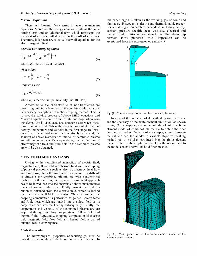
In view of the influence of the cathode geometric shape and the accuracy of the finite element simulation, as shown in Fig. (3), a mapping method is introduced into the finite element model of combined plasma arc to obtain the finer hexahedral meshes. Because of the steep gradients between the cathode and the anodes, a variable step-size meshing method has to be also introduced into the finite element model of the combined plasma arc. Then the region near to the model center line will be hold finer meshes.
Fig. (3). Mesh generation of the finite element model of the computational domain.
Jet Characteristics of Combined Plasma Arc The Open Mechanical Engineering Journal, 2011, Volume 5 81
Boundary Conditions
Due to the finite element model of combined plasma arc being axisymmetric, a quarter of this model is regarded as the substitution of whole calculation model to save compu-tation time, and its boundary conditions are shown in Table 1. For solving the potential equation, the working current passing through tungsten cathode is considered as uniform, so the current density of AB can be taken from the investi-gation of Lee [10]. At the anode surfaces FG and JL, the electrical potential is assumed to be zero. Meanwhile, ∂Φ/∂n=0 has been set on other places to represent the condition that no current flow crosses this boundary. For solving the momentum and energy equations, at BE and FG, a temperature of 3000K is assumed. An adiabatic condition is applied to the symmetrical surface EF. At other surfaces, the temperature is assumed to be 1000K. Furthermore, at the interior wall of the nozzle IL, wall of the cathode BE and anode surface FG, a no-slip condition is used. At the gas outlet GH, relative pressure P is assumed to 0. ∂u/∂r=0, v=0, w=0 are specified to the symmetrical surface AF and shielding gas inlet HI. Along the working gas inlet BL, the radial and azimuthal velocity components are neglected, and the axial velocity component is determined from the equation of the pipe flow [10] as follows:
( )( )
( )
( )( )
22 2 2 2
2 2 1
2 1
02
2 2
2 14 4
2 1
2 1
ln /
ln /2
ln /
r RR r R R
R RQu
R RR R
R R
!"
# $% + %& '& '
( )=
# $%& '% +& '& '( ) (9)
where Q is argon flow rate, R1 is the cathode radius and R2 is the internal radius of the shielding nozzle. Table 1. Boundary Conditions for the Solution of the Finite
Element Model of the Combined Plasma arc. (“-” Substitutes Natural Boundary Conditions)
u v w Φ T
AB 0 0 0 I 3000K
AE 0 0 0 - 3000K
BE 0 0 0 - 3000K
EF 0 / 0v r! ! = / 0w !" " = - -
FG 0 0 0 0 3000K
GH - - - - 1000K
HI / 0u z! ! = 0 0 - 1000K
IJ 0 0 0 0 1000K
JK 0 0 0 0 1000K
KL 0 0 0 0 1000K
LB u0 0 0 - 1000K
In addition, in the process of analysis of electro- mag-netic coupling field, magnetic lines of force are assumed to perpendicularly pass the symmetry plane and the boundary condition of the magnetic vector potential being zero is imposed on other surfaces in the calculation domain of the combined plasma arc.
Technique of Solution
Owing to the physical environment approach being mostly applied into the iterative analysis on coupled pheno-mena, in this paper, three physical environment files are created by finite element software ANSYS, including electric field, magnetic field and flow field. In the finite element analysis process, the operation command LDREAD is introduced to help these physical environment files successively correlated, that is, the results from one file can be loaded into another file using LDREAD. To ensure above iterative analysis convergent, a minor convergence of tempe-rature is set, which results from the normalization value of the temperature change between two adjacent iterative steps. In addition, to make argon gas fully ionize, a temperature of 100000K is imposed to the region of arc column in the initial calculation of electric field. Convergence is declared when the following condition is satisfied:
1
1
1
0.01
N k k
i ii
N k
ii
T T
T
!
!
"
=
=
"
#
(10) where N is the total number of nodes, Tk-1 i and Tk i are the upper iterative (k-1) temperature and current k temperature, respectively.
4. CALCULATION AND DISCUSSION
The process parameters adopted in the simulation are that the diameter of tungsten cathode is 1mm, its cone angle and length in the calculation domain is 60° and 3mm respect-ively, the interior radius of nozzle inlet and outlet is 3.5mm, its length is 6mm, and the radius of workpiece anode is 7mm. Moreover, the working current I is 15A, 20A and 25A, respectively. The distance D from the nozzle outlet to the workpiece anode is 6mm, 7mm and 8mm, respectively. The argon gas flow rate Q is 4L/min, 5L/min and 6L/min, respectively.
The Distributions of Current Density and Electromag-netic Force
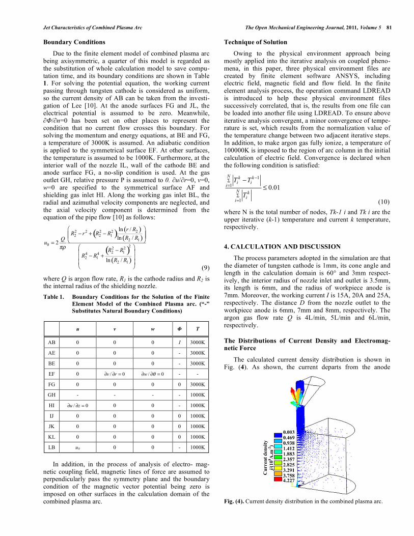
The calculated current density distribution is shown in Fig. (4). As shown, the current departs from the anode
Fig. (4). Current density distribution in the combined plasma arc.
82 The Open Mechanical Engineering Journal, 2011, Volume 5 Meng and Dong
surface and enters the electrode tip through the tungsten cathode spot. The current density achieves highest value at the cathode tip for its smaller area and higher temperature. Furthermore, due to the effect of temperature distribution of combined plasma arc on argon gas electric conductivity, which affects current density distribution of combined plasma arc, the current density becomes larger with axial distance nearing to the cathode, and decreases with radial distance increasing. Fig. (5) shows the calculated distribution of the electromagnetic force both in the arc column and tungsten cathode. Based on the left-hand rule, the direction of electromagnetic force can be determined with the current density and magnetic flux density. As shown, in the region of combined plasma arc column, the direction of electro-magnetic force is inward and downward, which compels the combined plasma arc to flow towards the workpiece anode and to be compressed at the same time. Furthermore, it can be seen that the electromagnetic force at the cathode tip is larger than the one at the lower portion of the arc, which also makes the combined plasma arc flow downward and inward.
Fig. (5). Electromagnetic force distribution in the combined plasma arc.
The Distributions of Temperature and Velocity
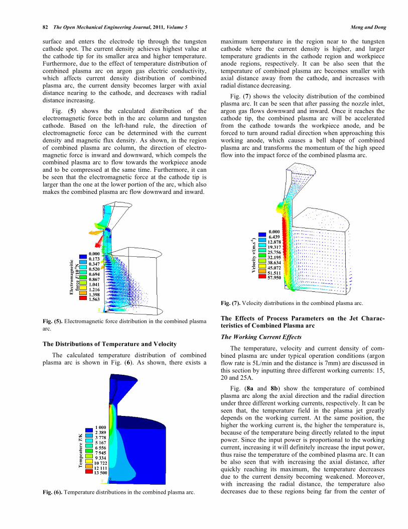
The calculated temperature distribution of combined plasma arc is shown in Fig. (6). As shown, there exists a
Fig. (6). Temperature distributions in the combined plasma arc.
maximum temperature in the region near to the tungsten cathode where the current density is higher, and larger temperature gradients in the cathode region and workpiece anode regions, respectively. It can be also seen that the temperature of combined plasma arc becomes smaller with axial distance away from the cathode, and increases with radial distance decreasing. Fig. (7) shows the velocity distribution of the combined plasma arc. It can be seen that after passing the nozzle inlet, argon gas flows downward and inward. Once it reaches the cathode tip, the combined plasma arc will be accelerated from the cathode towards the workpiece anode, and be forced to turn around radial direction when approaching this working anode, which causes a bell shape of combined plasma arc and transforms the momentum of the high speed flow into the impact force of the combined plasma arc.
Fig. (7). Velocity distributions in the combined plasma arc.
The Effects of Process Parameters on the Jet Charac-teristics of Combined Plasma arc
The Working Current Effects
The temperature, velocity and current density of com-bined plasma arc under typical operation conditions (argon flow rate is 5L/min and the distance is 7mm) are discussed in this section by inputting three different working currents: 15, 20 and 25A. Fig. (8a and 8b) show the temperature of combined plasma arc along the axial direction and the radial direction under three different working currents, respectively. It can be seen that, the temperature field in the plasma jet greatly depends on the working current. At the same position, the higher the working current is, the higher the temperature is, because of the temperature being directly related to the input power. Since the input power is proportional to the working current, increasing it will definitely increase the input power, thus raise the temperature of the combined plasma arc. It can be also seen that with increasing the axial distance, after quickly reaching its maximum, the temperature decreases due to the current density becoming weakened. Moreover, with increasing the radial distance, the temperature also decreases due to these regions being far from the center of

Jet Characteristics of Combined Plasma Arc The Open Mechanical Engineering Journal, 2011, Volume 5 83
arc column and the influence of the turbulent boundary layers.
Fig. (8a). Effect of working currents on the axial temperature.
Fig. (8b). Effect of working currents on the radial temperature.
Figs. (8c and 9d) show the velocity along the axial direction and current density along the radial direction on the workpiece anode, respectively. As shown, the influences of working currents on the velocity of combined plasma arc are similar to the effect on temperature, due to the electromag-netic force having a significant effect on the shape of the velocity profiles and its effect being more important with
Fig. (8c). Effect of working currents on the axial velocity.
increasing current. At the same position, the relatively higher working current corresponds to relatively higher velocity and current density. With increasing the axial distance, after quickly reaching its maximum, the velocity decreases in succession. Due to the violent thermal expansion of the high temperature plasma gas, increasing the working current, argon density decreases, the degree of thermal ionization and electrical conductivity increase, which induce the peak value
and radius of the current density on the workpiece anode to be increased.
Fig. (8d). Effect of working currents on the radial current density on the anode.
The Argon Gas Flow Rate Effects
The temperature, velocity and current density of the combined plasma arc under typical operation conditions (the working current is 15A and the distance is 7mm) are discussed in this section by inputting three different argon gas flow rates: 4, 5, 6L/min. Fig. (9a and 9b) show the temperature distributions along the axial and radial direction, respectively, under different argon gas flow rates. It can be seen that the higher the flow rates of argon gas, the higher the temperature are along the axial and radial direction (r<2mm). However, the tempera-ture slightly increases with argon gas flow rate increasing,
Fig. (9a). Effect of argon flow rate on the axial temperature.
Fig. (9b). Effect of argon flow rate on the radial temperature.

84 The Open Mechanical Engineering Journal, 2011, Volume 5 Meng and Dong
even the temperature along the radial direction (r>2mm) decreases with argon flow rate increasing. The reason is that increasing argon flow rate will expand the length of plasma arc in the nozzle and induce the arc voltage and relevant input power to be increased, which results in higher tempera-ture of combined plasma arc. On the other hand, increasing argon flow rate will force the more argon gas to be heated and ionized, which brings on the temperature descending. Completely considered above two effects of argon flow rate on the temperature, it can be concluded that the temperature is not proportional to argon flow rate. In addition, it will enhance the compression effect on combined plasma arc with the increase of argon flow rate increase, and reduce the radius of the temperature distribution along the radial direc-tion because of its energy density distribution concentrating. Fig. (9c and 9d) present the velocity distribution along the axial direction and the current density distribution on the anode along the radial direction, respectively, under different argon flow rates. As shown, the influence of argon flow rate on the velocity is similar to its effect on the temperature of combined plasma arc. It can be also seen that the peak value of current density on the workpiece anode along its radial direction increases with the accretion of argon flow rate, however, the radius of the current density distribution reduces with increasing argon flow rate.
Fig. (9c). Effect of argon flow rate on the axial velocity.
Fig. (9d). Effect of argon flow rate on the radial current density on the anode.
The Effects of the Distance from the Nozzle Outlet to the Workpiece Anode
The temperature, velocity and current density of com-bined plasma arc under typical operation conditions (the
working current is 15A and argon flow rate is 5L/min) are discussed in this section by inputting three different distances from the nozzle outlet to the anode: 6, 7, 8mm. Fig. (10a and 10b) show the temperature distributions along the axial and radial direction, respectively, under different distances from the nozzle outlet to the workpiece anode. As shown, increasing the distance, the temperature along the axial direction slightly increases. However, along the radial direction, the temperature near to the workpiece anode decreases. The reason is that increasing the distance will lengthen the combined plasma arc and the arc voltage to be ascended, which will consequentially lead to the increase of the temperature along the axial direction. On the other hand, increasing the length of combined plasma arc will result in the extension of contact field with the ambient cool gas and the increase of the heat loss, which will cones-quentially bring on the decrease of the temperature near to the anode along the radial direction.
Fig. (10a). Effect of the distance on the axial temperature.
Fig. (10b). Effect of the distance on the radial temperature.
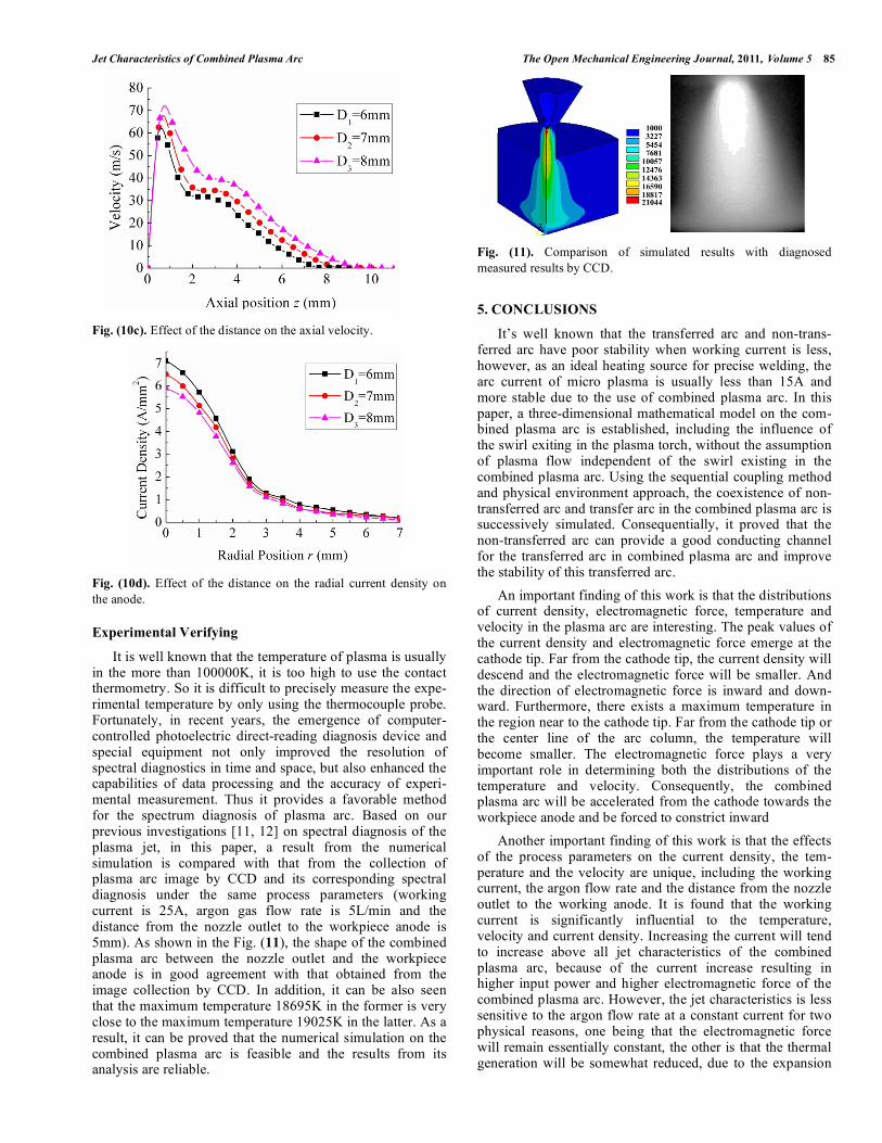
Fig. (10c and 10d) present the velocity distribution along the axial direction and the current density distribution on the anode radial direction, respectively, under different argon flow rates. As shown, the influence of the distance on the velocity is similar to the effect on the temperature along axial direction. The longer the distance from the nozzle outlet to the anode, the higher the velocity is. On the contrary, the peak value of current density along the anode radial direction is reciprocal proportional to the distance. However, the longer the distance, the more the radius of current density along anode radial direction is, due to the expansion of the conduction region on the workpiece anode with the distance increasing.
Jet Characteristics of Combined Plasma Arc The Open Mechanical Engineering Journal, 2011, Volume 5 85
Fig. (10c). Effect of the distance on the axial velocity.
Fig. (10d). Effect of the distance on the radial current density on the anode.
Experimental Verifying
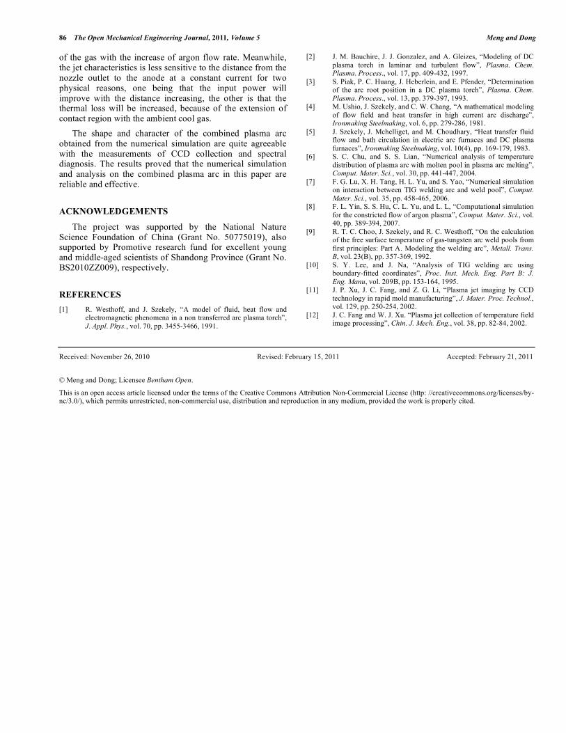
It is well known that the temperature of plasma is usually in the more than 100000K, it is too high to use the contact thermometry. So it is difficult to precisely measure the expe-rimental temperature by only using the thermocouple probe. Fortunately, in recent years, the emergence of computer-controlled photoelectric direct-reading diagnosis device and special equipment not only improved the resolution of spectral diagnostics in time and space, but also enhanced the capabilities of data processing and the accuracy of experi-mental measurement. Thus it provides a favorable method for the spectrum diagnosis of plasma arc. Based on our previous investigations [11, 12] on spectral diagnosis of the plasma jet, in this paper, a result from the numerical simulation is compared with that from the collection of plasma arc image by CCD and its corresponding spectral diagnosis under the same process parameters (working current is 25A, argon gas flow rate is 5L/min and the distance from the nozzle outlet to the workpiece anode is 5mm). As shown in the Fig. (11), the shape of the combined plasma arc between the nozzle outlet and the workpiece anode is in good agreement with that obtained from the image collection by CCD. In addition, it can be also seen that the maximum temperature 18695K in the former is very close to the maximum temperature 19025K in the latter. As a result, it can be proved that the numerical simulation on the combined plasma arc is feasible and the results from its analysis are reliable.
Fig. (11). Comparison of simulated results with diagnosed measured results by CCD.
5. CONCLUSIONS
It’s well known that the transferred arc and non-trans-ferred arc have poor stability when working current is less, however, as an ideal heating source for precise welding, the arc current of micro plasma is usually less than 15A and more stable due to the use of combined plasma arc. In this paper, a three-dimensional mathematical model on the com-bined plasma arc is established, including the influence of the swirl exiting in the plasma torch, without the assumption of plasma flow independent of the swirl existing in the combined plasma arc. Using the sequential coupling method and physical environment approach, the coexistence of non-transferred arc and transfer arc in the combined plasma arc is successively simulated. Consequentially, it proved that the non-transferred arc can provide a good conducting channel for the transferred arc in combined plasma arc and improve the stability of this transferred arc. An important finding of this work is that the distributions of current density, electromagnetic force, temperature and velocity in the plasma arc are interesting. The peak values of the current density and electromagnetic force emerge at the cathode tip. Far from the cathode tip, the current density will descend and the electromagnetic force will be smaller. And the direction of electromagnetic force is inward and down-ward. Furthermore, there exists a maximum temperature in the region near to the cathode tip. Far from the cathode tip or the center line of the arc column, the temperature will become smaller. The electromagnetic force plays a very important role in determining both the distributions of the temperature and velocity. Consequently, the combined plasma arc will be accelerated from the cathode towards the workpiece anode and be forced to constrict inward Another important finding of this work is that the effects of the process parameters on the current density, the tem-perature and the velocity are unique, including the working current, the argon flow rate and the distance from the nozzle outlet to the working anode. It is found that the working current is significantly influential to the temperature, velocity and current density. Increasing the current will tend to increase above all jet characteristics of the combined plasma arc, because of the current increase resulting in higher input power and higher electromagnetic force of the combined plasma arc. However, the jet characteristics is less sensitive to the argon flow rate at a constant current for two physical reasons, one being that the electromagnetic force will remain essentially constant, the other is that the thermal generation will be somewhat reduced, due to the expansion
86 The Open Mechanical Engineering Journal, 2011, Volume 5 Meng and Dong
of the gas with the increase of argon flow rate. Meanwhile, the jet characteristics is less sensitive to the distance from the nozzle outlet to the anode at a constant current for two physical reasons, one being that the input power will improve with the distance increasing, the other is that the thermal loss will be increased, because of the extension of contact region with the ambient cool gas. The shape and character of the combined plasma arc obtained from the numerical simulation are quite agreeable with the measurements of CCD collection and spectral diagnosis. The results proved that the numerical simulation and analysis on the combined plasma arc in this paper are reliable and effective.
ACKNOWLEDGEMENTS
The project was supported by the National Nature Science Foundation of China (Grant No. 50775019), also supported by Promotive research fund for excellent young and middle-aged scientists of Shandong Province (Grant No. BS2010ZZ009), respectively.
REFERENCES [1] R. Westhoff, and J. Szekely, “A model of fluid, heat flow and
electromagnetic phenomena in a non transferred arc plasma torch”, J. Appl. Phys., vol. 70, pp. 3455-3466, 1991.
[2] J. M. Bauchire, J. J. Gonzalez, and A. Gleizes, “Modeling of DC plasma torch in laminar and turbulent flow”, Plasma. Chem. Plasma. Process., vol. 17, pp. 409-432, 1997.
[3] S. Piak, P. C. Huang, J. Heberlein, and E. Pfender, “Determination of the arc root position in a DC plasma torch”, Plasma. Chem. Plasma. Process., vol. 13, pp. 379-397, 1993.
[4] M. Ushio, J. Szekely, and C. W. Chang, “A mathematical modeling of flow field and heat transfer in high current arc discharge”, Ironmaking Steelmaking, vol. 6, pp. 279-286, 1981.
[5] J. Szekely, J. Mchelliget, and M. Choudhary, “Heat transfer fluid flow and bath circulation in electric arc furnaces and DC plasma furnaces”, Ironmaking Steelmaking, vol. 10(4), pp. 169-179, 1983.
[6] S. C. Chu, and S. S. Lian, “Numerical analysis of temperature distribution of plasma arc with molten pool in plasma arc melting”, Comput. Mater. Sci., vol. 30, pp. 441-447, 2004.
[7] F. G. Lu, X. H. Tang, H. L. Yu, and S. Yao, “Numerical simulation on interaction between TIG welding arc and weld pool”, Comput. Mater. Sci., vol. 35, pp. 458-465, 2006.
[8] F. L. Yin, S. S. Hu, C. L. Yu, and L. L, “Computational simulation for the constricted flow of argon plasma”, Comput. Mater. Sci., vol. 40, pp. 389-394, 2007.
[9] R. T. C. Choo, J. Szekely, and R. C. Westhoff, “On the calculation of the free surface temperature of gas-tungsten arc weld pools from first principles: Part A. Modeling the welding arc”, Metall. Trans. B, vol. 23(B), pp. 357-369, 1992.
[10] S. Y. Lee, and J. Na, “Analysis of TIG welding arc using boundary-fitted coordinates”, Proc. Inst. Mech. Eng. Part B: J. Eng. Manu, vol. 209B, pp. 153-164, 1995.
[11] J. P. Xu, J. C. Fang, and Z. G. Li, “Plasma jet imaging by CCD technology in rapid mold manufacturing”, J. Mater. Proc. Technol., vol. 129, pp. 250-254, 2002.
[12] J. C. Fang and W. J. Xu. “Plasma jet collection of temperature field image processing”, Chin. J. Mech. Eng., vol. 38, pp. 82-84, 2002.
Received: November 26, 2010 Revised: February 15, 2011 Accepted: February 21, 2011 © Meng and Dong; Licensee Bentham Open.
This is an open access article licensed under the terms of the Creative Commons Attribution Non-Commercial License (http: //creativecommons.org/licenses/by-nc/3.0/), which permits unrestricted, non-commercial use, distribution and reproduction in any medium, provided the work is properly cited.