Embed Size (px)
Citation preview

Purdue UniversityPurdue e-PubsInternational Refrigeration and Air ConditioningConference School of Mechanical Engineering
2016
Experimental And Numerical Investigations ofEjector Jet Refrigeration System With PrimaryStream SwirlJiautheen Parveen BanuIndian Institute of Technology Madras, India, [email protected]
Jawali Maharudrappa MallikarjunaIndian Institute of Technology Madras, India, [email protected]
Annamalai ManiIndian Institute of Technology Madras, India, [email protected]
Follow this and additional works at: http://docs.lib.purdue.edu/iracc
This document has been made available through Purdue e-Pubs, a service of the Purdue University Libraries. Please contact [email protected] foradditional information.Complete proceedings may be acquired in print and on CD-ROM directly from the Ray W. Herrick Laboratories at https://engineering.purdue.edu/Herrick/Events/orderlit.html
Parveen Banu, Jiautheen; Mallikarjuna, Jawali Maharudrappa; and Mani, Annamalai, "Experimental And Numerical Investigations ofEjector Jet Refrigeration System With Primary Stream Swirl" (2016). International Refrigeration and Air Conditioning Conference. Paper1576.http://docs.lib.purdue.edu/iracc/1576
2045, Page 1
16th International Refrigeration and Air Conditioning Conference at Purdue, July 11-14, 2016
Experimental and Numerical Investigations of Ejector Jet Refrigeration
System with Primary Stream Swirl
Parveen Banu JIAUTHEEN, Mallikarjuna JAWALI MAHARUDRAPPA, Mani ANNAMALAI *
Indian Institute of Technology Madras, Department of Mechanical Engineering, Refrigeration and
Air-conditioning Laboratory, Chennai, Tamilnadu, India
(* Corresponding Author: +91- 44- 2257 4666, + 91 44 2257 0509, [email protected], )
ABSTRACT
Among the various heat powered refrigeration systems, vapour jet refrigeration system (VJRS) is attractive because
of its simple and rugged nature. Ejector is a key component in VJRS and the performance of the whole system
depends on the effective performance of the ejector, which in-turn could be improved by proper mixing of primary
and secondary streams. This paper focuses on numerical and experimental studies of air ejector to analyse the
influence of swirl on the performance of the system. Three-dimensional numerical analysis has been carried out for
the ejector with and with no-swirl and the same has been verified with experimental studies using flow visualisation
technique, particle image velocimetry (PIV). Swirl is generated in the primary stream by incorporating fixed vane
swirler of camber angle of 10°, just upstream of the convergent portion of the primary nozzle which is a convergent-
divergent (CD) nozzle. Velocity vectors obtained from PIV and CFD were compared and found that the results fall
within an acceptable range. Studies have been carried out for an ejector under various primary stream pressures,
with secondary and discharge pressure being open to atmosphere. By incorporating swirler of Type-2, in the primary
nozzle, it has been observed that, swirl induced is low to have a significant improvement in entrainment ratio
(around 2%) of ejector whereas swirler of Type-1 resulted in 5% improvement in performance compared to ejector
with no-swirl.
1. INTRODUCTION
Among the various heat operated refrigerated systems, vapour jet refrigeration system (VJRS) is attractive because
of its simple and rugged nature. Merits of ejector is that, it can be operated with low grade energy by utilizing the
heat from solar energy, waste heat from industrial exhaust, automobile exhaust, etc. Literature revealed that the
minimum temperature at which it can be operated is about 65°C (Selvaraju and Mani, 2004, Shankarlal and Mani,
2007 a and b). Besides that, this system requires relatively less maintenance as it has no moving parts and it
consumes negligible electrical energy for recirculating pump used in the system.
2. LITERATURE
Ejector plays a major role in vapour jet refrigeration system. Performance of the whole VJRS majorly depends on
the efficient performance of ejector, besides the other components of the system. The ejector is also known as
thermo-compressor, because it utilizes thermal energy and momentum exchange between primary and secondary
streams, for compression process. Primary stream can also be known as motive or driving stream and secondary
stream as induced or driven stream. Plenty of research works since very long, have been focusing on improving the
efficiency of the ejector. Progress of the ejector analysis techniques have been reviewed in various papers
(Chunnanond, 2004, Chen, 2013 and Banu, 2014). More work could be found on the geometrical configurations of
ejector in the light of improving the performance. Also some of the other techniques like constant rate of momentum
exchange, petal nozzle, self- rotating skew, movable primary nozzle, thermally driven rotor-vane/ pressure exchange
ejector, swirl flows etc., had been investigated. Besides geometrical configuration, the key parameter which decides
the performance is mixing of the primary and secondary streams. Seouk Park (2009, 2010) numerically investigated
the improvement in entraining efficiency using a swirl component in primary nozzle of ejector used for multi-effect
desalination system. Authors analysed the effect of swirled motive steam inflow on entrainment ratio (ER) by
contours of Mach number, isobars, radial velocities and shock patterns. Also, they highlighted that swirl effect

2045, Page 2
16th International Refrigeration and Air Conditioning Conference at Purdue, July 11-14, 2016
increases the contact time between the motive and suction streams along with the increased effect of shear force,
thereby ER could be increased. Performance enhancement through better mixing could be achieved by various
methods, such as tangential injection of the streams, fixed vane and rotating swirl generators, inserting tabs in the
ejector etc. This paper focuses on the performance analysis of the ejector with the introduction of swirl to the
primary stream by incorporating fixed vane swirl generator inside the primary nozzle. Based on three-dimensional
CFD studies on ejector analysis, it is confirmed that mixing is enhanced using swirl generator by about 5% for
swirler design (Type-1, shown in Figure 2), thereby improved performance is achieved (Banu et al., 2014).
3. DESCRIPTION OF EJECTOR OPERATION
3.1. Ejector Ejector is a major component in VJRS as shown in Figure 1, comprises of four parts: primary nozzle, suction
chamber, constant area mixing section (also called ejector throat) and diffuser.
Figure 1: Photographic representation of ejector
Primary stream at high pressure expands in the primary nozzle of ejector and exits at supersonic velocity which
entrains the secondary stream from the vacuum chamber (which acts as an evaporator of VJRS), where low pressure
needs to be achieved. Both the streams mix together at constant pressure, exchange momentum, gets compressed
partially through a normal shock in the constant area tube and are further compressed in diffuser. Thus compression
of secondary stream has been achieved by the exchange of momentum between streams.
3.2 Swirl generator Swirl generator with vane details, used in the present study, for generating swirl in the primary stream is shown in
Figure 3. The swirl generated by this solid vane inserts are complex in nature, in contrast to that of tangential inlets
type of swirl generation (Abdelhafez and Gupta, 2010). In this present study, it has been attempted to study the flow
patterns inside the ejector, with the effect of swirl. The swirl generator is placed just upstream of convergent portion
of the primary nozzle. The vane is of aerofoil cross-section with the leading and trailing edge, arranged
circumferentially inside the bush and is inserted inside the primary nozzle just upstream of the convergent portion of
the primary nozzle. Figure 2 and Figure 3, depicts the two designs of swirler Type-1 and Type-2. Type-1, in which
vanes are arranged in a fashion that it act as a separate ducts through which air flow occurs. It enhances the
performance by around 5 % (Banu et al., 2014). Type-2 swirler is of aerofoil vanes with leading and trailing edge.
Air enters towards leading edge and it swirls according to the angle of vane through the trailing edge. The present
study on swirler, Type-2, with 3vanes is of 10° camber angle, which induces swirl of low magnitude, that it has a
less significant improvement in the ejector performance, similar to the observation made by the author on the studies
of turbulent mixing of jets (Schetz and Swanson 1973).

2045, Page 3
16th International Refrigeration and Air Conditioning Conference at Purdue, July 11-14, 2016
(a) (b)
Figure 2: (a) Solidworks model (b) single vane details of swirler – Type-1
(a) (b) (c) (d)
Figure 3: Pictorial view of swirler (a) top view (b) front view of 3vanes (c) 5vanes (d) vane details – Type-2
4. NUMERICAL STUDIES
Through mass, momentum and energy governing equations, one-dimensional studies (Selvaraju and Mani 2004)
were carried out using MATLAB and critical dimensions of ejector have been arrived for the various operating
conditions. The ejector geometrical dimensions have been optimized to operate under wide operating conditions.
The optimum dimensions of the ejector have been arrived as shown in Table 1.
Table 1: Dimensions of ejector
Numerical analysis of supersonic air ejector has been carried out for the arrived geometry of the ejector with swirl
and with no-swirl, under various operating conditions using computational commercial software, CFD. Air flow is
considered as compressible, steady state, with turbulent in nature. Thermodynamic and transport properties of air are
kept constant. Density of air is assumed to follow an ideal gas equation. Governing equations of mass, momentum,
energy and turbulence were solved using density based solver coupled with implicit scheme, which is more suitable
for compressible flow analysis. Though steady state is considered, the governing equations were solved by finite
volume technique in time marching scheme. The convection term is discretized with second order upwind scheme,
while turbulent kinetic energy and turbulent dissipation rate is of first order upwind scheme. The turbulence model
Part name with dimensions mm Part name with dimensions mm
Primary nozzle throat diameter 2.0 Mixing tube diameter 9.2
Primary nozzle exit diameter 3.2 Mixing tube length 100
Primary nozzle area- ratio 2.56 Ejector area-ratio 21
Distance of primary nozzle tip
from mixing tube entry
10 Diffuser diameter 25
Suction chamber convergent
angle
30º Diffuser length 90

2045, Page 4
16th International Refrigeration and Air Conditioning Conference at Purdue, July 11-14, 2016
chosen is SST-k-ω, as it is the most common model suitable for high speed spreading jets and shocks at on-design
and off-design operating conditions (Bartosewiz et al., 2006). Flow is considered to be adiabatic flow with standard
wall function. Numerical computation analysis is said to be converged, when the residues of the variables such as
mass, momentum, energy, turbulent kinetic energy (k) and turbulent dissipation rate (β), falls below 10-6. Also the
mass balance among the inlets and outlet should remain constant. Boundary conditions used were pressure inlets for
primary and secondary flow inlet and pressure outlet for the diffuser outlet.
4.1 Validation of CFD Validation of numerical analysis using CFD as shown in Figure 4, were carried out by comparing the key
performance parameter named entrainment ratio (ER) with experimental studies. Entrainment ratio is the ratio
between secondary and primary mass flow rate. The ER obtained by CFD has been compared with that of
experimental studies and it has been found that the values varies within ± 5%.
Figure 4: Comparison of entrainment ratio from CFD and experimental analysis of R134a ejector
(Selvaraju and Mani, 2005)
4.2 Grid independent studies Grid independent study has been performed for obtaining the mesh independent solution. It is done for the mesh
sizes of 3, 5, 7 and 12 hundred thousand cells. It has been observed that the deviation of centerline velocity along the
ejector is about 5% among 7 and 12 hundred thousand mesh cells. So the grid size chosen for further computational
analysis is of 7 hundred thousand mesh, with minimum orthogonal quality of 0.525, maximum aspect ratio of
10.956 and average skewness of 0.234.
.
5. EXPERIMENTAL SETUP
5.1 Description of experimental set up Experimental setup used for the study of influence of swirl generator on the performance of the ejector comprises of
an air compressor with a reservoir of 100 liters, supplying air at a maximum pressure of about 10 bar, transparent
ejector, optical table, PIV set up and measuring instruments. Ejector is supplied with compressed air at a constant
pressure using pressure regulator. Primary air mass flow rate can be measured by rotameter connected to the pipe
line. Ejector to be analysed is mounted on the optical table. The secondary inlet to the ejector is equipped with an
orifice meter for measuring the secondary flow. Also the secondary inlet is connected to the vacuum chamber.
Various pressures simulating the evaporator conditions can be done by controlling the opening of the vacuum
chamber using ball valve connected to the chamber. The present study is based on the secondary and discharge
streams open to atmosphere, so the vacuum chamber and discharge pipe from diffuser, controlled by valves
respectively are kept fully open during experimentation. The static pressure of primary, secondary and discharge
streams are measured with pressure transducers.

2045, Page 5
16th International Refrigeration and Air Conditioning Conference at Purdue, July 11-14, 2016
Figure 5: Pictorial representation of PIV experimental setup
The static pressure will be approximately equal to the total pressure, as the inlet and outlet velocities are very low
compared to the supersonic condition of nozzle. The primary pressure, secondary pressure and discharge pressure
entering the ejector are measured using pressure transducers. It has been calibrated with an inclined U-tube mercury
manometer. Primary mass flow rates are measured with rotameter which has an uncertainty of +/- 0.01g/sec. The
secondary mass flow rates are determined using orifice plate equipped with inclined U-tube manometer with
pressure taps at flanges.
5. 2 Description of PIV arrangement PIV set-up as shown in Figure 2, comprises of charge-coupled device (CCD) camera, ND-YAG laser with optical
arrangement like spherical lens which focus the beam in the study zone of ejector, a cylindrical lens, which converts
laser beam to thin sheet, seeding arrangement, synchronizer which synchronizes the camera, laser and seeder. The
thickness of the laser sheet is about 0.5mm with pulsed illumination. Also image processing software, which process
the captured image for better understanding of the flow patterns. Laser used is ND-YAG Double-pulsed Laser of
wavelength 532 Nm, energy 200 mJ, which illuminates the ejector and the flow is captured by CCD camera. PIV
captures the image of the flow by passing laser sheet perpendicular to the ejector axis. The vectors are calibrated
using a calibration plate in which grids of standard spacing were made. The purpose of seeding is to capture the flow
patterns by tracing the laser illuminated seeding particles. Seeding done by adding, Diethyl- hexasebacate in the
seeding device, which allows the atomized oil droplets of diameter of about 1 micro-meter with the main air flow for
the purpose of capturing the flow.
6. RESULTS AND DISCUSSION
Experimental analysis has been carried out using PIV to study the influence of swirler Type-2, with 3vanes, over the
performance of ejector under a set of operating conditions. The experimental results were compared with numerical
computational analysis. Ejector is operated at various primary pressures for evaluating the performance of ejector
with secondary and discharge streams open to atmosphere. Mass flow rate of primary stream and secondary stream
is noted corresponding to the operating conditions. Based on this, global performance evaluating parameter named,
entrainment ratio which is the ratio of secondary flow rate to the primary flow rate is calculated. Also using PIV, the
velocity distribution, flow patterns inside the ejector are compared for ejector with and with no-swirl.

2045, Page 6
16th International Refrigeration and Air Conditioning Conference at Purdue, July 11-14, 2016
6.1 Zone of study PIV studies of ejector is analysed as a first step, in the region of primary nozzle exit to the mixing tube entry as
shown in Figure 6.
Figure 6: Zone of study Figure 7: Swirl number at various cross-sectional planes along
the ejector
6.2 Swirl number calculation Swirl number is defined as
2
x
x
u u rdAS
R u dA
θρ
ρ= ∫
∫ (1)
where, S - swirl number r - radial coordinate
R - maximum radius of the geometry A - area of cross section
xu ,uθ - axial and tangential velocity components ρ - density
Figure 7 shows that swirler number, calculated by equation (1), at various cross sectional planes just upstream of the
swirler to the downstream of the mixing tube. It has been observed that swirl number, S, at the plane just after
swirler is higher and the swirl direction is counterclockwise. Then it gradually reduces and becomes zero at the
primary nozzle exit. Further, from nozzle exit to the mixing tube entry plane, there is slight increase in swirl number,
due to the effect of tangential entry of secondary stream mixing with primary stream. From this, it is clear that the
swirl decays with in the primary nozzle itself. This implies that the swirl induced by the 10° aerofoil cross section swirler of this design is so low that it decays within the nozzle, and have a very less significant effect in the
performance of the ejector.
6.3 Effect of swirl on the ejector performance Performance of ejector with swirl has been investigated at various motive pressure and compared the same with no-
swirl condition. Due to the swirling nature of the primary stream induced by the swirler, the axial velocity gets
reduced and tangential velocity increased, when compared to no-swirl case. The same has been observed from the
Figure 8, that velocity of the ejector with swirl is lesser that of no-swirl ejector. At off-design condition, the primary
stream upon expansion in the CD nozzle, experiences shock. If the primary pressure is too low, say, at 1 bar and 2
bar, normal shock occurs within the nozzle. At 3 bar primary pressure, shock occurs just downstream of the nozzle
exit. Shocks moves downstream with an increase in primary stream pressures. At 4 bar and above, it has been
1 - Before swirl plane , 2 - After swirl plane, 3 - Nozzle exit plane, 4 - Mixing tube entry plan , 5 - Mixing tube
entry 5mm downstream plane, 6 - Mixing tube entry 10mm downstream plane, 7 - Mixing tube entry 25mm
downstream plane, 8 - Mixing tube entry 75mm downstream plane

2045, Page 7
16th International Refrigeration and Air Conditioning Conference at Purdue, July 11-14, 2016
observed that primary stream experiences oblique shocks as the pressure at nozzle exit is lesser than that of mixing
chamber. Figure 9 shows the effect of swirl on the entrainment ratio at various primary stream pressures for Type-2
swirler. Due to the less swirl produced by the swirler of Type-2, the enhancement in entrainment ratio is not in a
considerable level for 3 vanes and even for 5 vanes observed from experimental studies. It has been observed that
the enhancement of performance is less than 2% for 3 vanes and around 2% for 5vanes, compared to ejector with
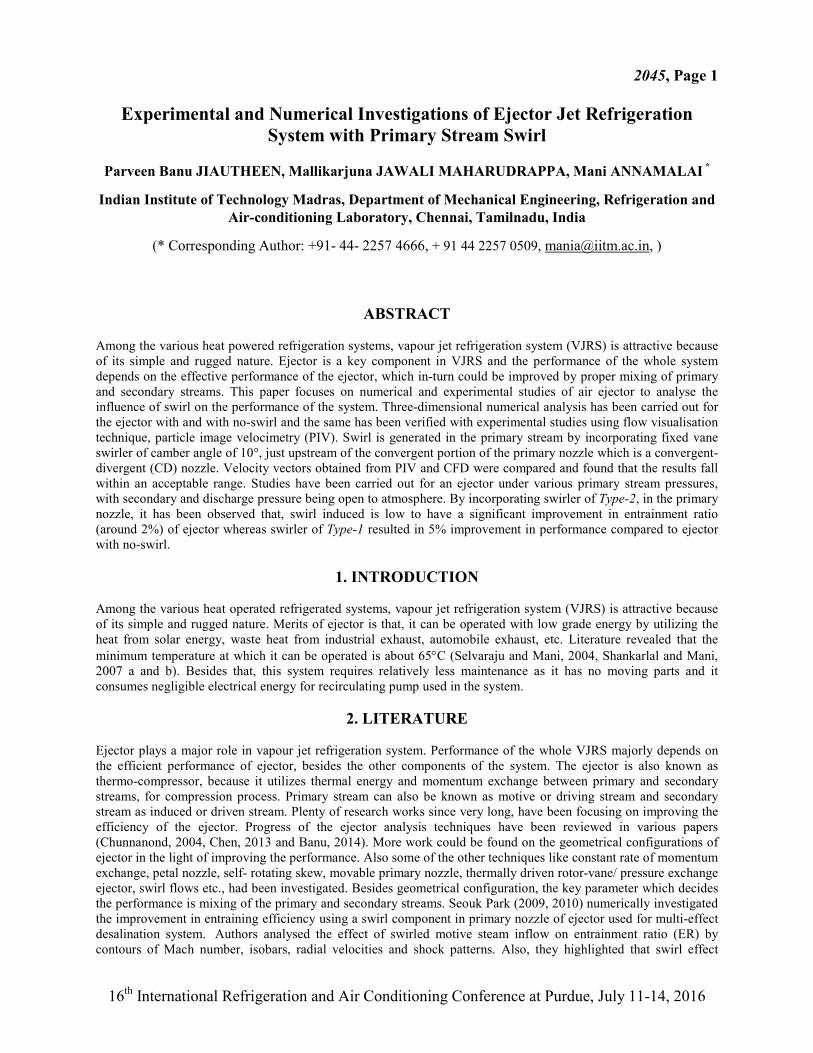
no-swirl. Figure 10 a and Figure 10 b, shows the influence of swirl on the ejector performance by comparing
velocity vectors of ejector with and with no-swirl case of CFD and PIV results.
Figure 8: Velocity distribution along ejector axis for ejector with and without swirl at various
primary pressures for Type-2 swirler
Figure 9: Effect of swirl on the entrainment ratio at various primary stream pressures for Type-2 swirler
2045, Page 8
16th International Refrigeration and Air Conditioning Conference at Purdue, July 11-14, 2016
(a) 1 bar no-swirl
CFD PIV
1 bar with swirl
CFD PIV
Figure 10a: Velocity vectors of CFD and PIV for ejector with swirl (Type-2, 3vanes) and with no-swirl at 1bar
gauge primary pressure

2045, Page 9
16th International Refrigeration and Air Conditioning Conference at Purdue, July 11-14, 2016
5 bar with no-swirl
CFD PIV
5bar with swirl
CFD PIV
Figure 10b: Velocity vectors of CFD and PIV for ejector with swirl (Type-2, 3vanes) and with no-swirl at 5bar
gauge primary pressure

2045, Page 10
16th International Refrigeration and Air Conditioning Conference at Purdue, July 11-14, 2016
CONCLUSION
This paper focused on the influence of swirl on the performance of ejector under a set of primary pressure,
while the secondary inlet and discharge outlet being open to atmosphere. Swirl generator is used for generating
swirl in the primary nozzle, placed just upstream of the primary nozzle. Three-dimensional numerical studies of
ejector with and with no-swirl were carried out with air as a working fluid using CFD software. Experimental
studies were also performed, for observing the entrainment ratio, by measuring the primary and secondary
stream mass flow rate. Further PIV studies were carried out for ejector in the zone of study (ie., from primary
nozzle outlet to the mixing tube entry). The CFD vectors were also validated with that of PIV results. The
results agrees well with PIV vectors. From the results it had been observed that the ER of no-swirl is 0.39, for
Type-2 swirler with 3vanes ER is 0.3945 and for 5vanes ER is 0.4. The swirl induced by this swirler (Type-2) is
low, that it has a very less significant effect on the performance improvement of ejector (less than 2% for 3
vanes and around 2% for 5vanes). Whereas, it has been reported that ER for Type-1 swirler is 0.415, which
produces an improvement in performance by about 5% (Banu et al., 2014). The influence of swirler design and
swirl angle on the ejector performance will be studied in future.
ACKNOWLEDGEMENT
It has been acknowledged that this current work is funded by Department of Science and Technology(DST)
DSTX/12-13/295/AMAN.
REFERENCES
Selvaraju, A. & Mani, A. (2004). Analysis of a vapor ejector refrigeration system with environment friendly
refrigerants. Int. J. Therm. Sci., 43, 915–921.
Sankarlal, T. & Mani, A. (a) (2007). Experimental investigations on ejector refrigeration system with ammonia.
Renewable Energy, 32, 1403–1413.
Sankarlal, T. & Mani, A. (b) (2007). Experimental studies on an ammonia ejector refrigeration system. Int.
Comm. Heat Mass Trans., 33, 224–230.
Selvaraju, A. & Mani, A. (2004). Analysis of an ejector with environment friendly refrigerants. Appl. Therm.
Eng., 24, 827 – 838.
Kanjanapon Chunnanond & Satha Aphornratana. (2004). Ejectors: Applications in refrigeration technology.
Renewable and Sustainable Energy Reviews, 8, 129–155.
Riffat, S. B., Jiang, L. & Gan, G. (2005). Recent development in ejector technology-a review. Int. J. Ambient
Energy, 26(1), 13-26.
PARVEEN BANU, J. & MANI, A. (2014). REVIEW ON EJECTOR OF VAPOUR JET REFRIGERATION
SYSTEM. Int. J. Air-Cond. Ref. 22(3), 1430003 [30 pages] DOI: 10.1142/S2010132514300031
Xiangjie Chen, Siddig Omer, Mark Worall, & Saffa Riffat, (2013). Recent developments in ejector refrigeration
technologies. Renewable and Sustainable Energy Reviews, 19, 629–651.
Seouk Park, I.L. (2009). Enhancement of entraining performance on thermal vapor compressor for multi-effect
desalination plants by swirl effects of motive steam. Numerical Heat Transfer, Part A, 56, 406-421.
Seouk Park, I. L. (2010). Numerical investigation of entraining performance and operational robustness of
thermal vapor compressor having swirled motive steam inflow. Desalination, 257, 206 – 211.
Abdelhafez, A. & Gupta, A. K. (2010). Swirling Airflow through a Nozzle: Choking Criteria. Journal of
Propulsion and Power, 26(4), 754-764.
Schetz, J. A. & Swanson, R. C. (1973). Turbulent Jet Mixing at High Supersonic Speeds. Zeitschrift fuer
Flugwissenschaften, 21(5), 166-173.
Bartosiewicz, Y., Aidoun, Z., & Mercadier, Y. (2006). Numerical assessment of ejector operation for
refrigeration applications based on CFD. Appl. Therm. Eng., 26, 604–612.
Selvaraju, A., & Mani, A. (2006). Experimental investigation on R134a vapour ejector refrigeration system, Int.
J. Refrig., 29, 1160-1166
Parveen Banu, J. Shaligram Tiwari & Mani, A. (2014). Three-dimensional Numerical Investigations on Ejector
of Vapour Jet Refrigeration System. Purdue conferences 2014, Purdue University Paper ID: 2291.


![CFD Simulation of Ejector in Steam Jet Refrigeration...to faultlessly. Anticipate those execution of the steam jet refrigeration framework, impacts of the essential nozzle’s [4]](https://img.dokumen.tips/doc/110x75/5e897add438ad91bf87773a4/cfd-simulation-of-ejector-in-steam-jet-refrigeration-to-faultlessly-anticipate.jpg)