Embed Size (px)
Citation preview
Advances in Aircraft and Spacecraft Science, Vol. 7, No. 6 (2020) 537-551
DOI: https://doi.org/10.12989/aas.2020.7.6.537 537
Copyright © 2020 Techno-Press, Ltd.
http://www.techno-press.org/?journal=aas&subpage=7 ISSN: 2287-528X (Print), 2287-5271 (Online)
Numerical simulation and investigation of jet impingement cooling heat transfer for the rotor blade
Amin Peiravi, Mohsen Agha Seyyed Mirza Bozorga and Alireza Mostofizadeha
Department of Mechanical & Aerospace Engineering, Malek-Ashtar University of Technology, Isfahan, Iran
(Received June 25, 2019, Revised June 24, 2020, Accepted June 29, 2020)
Abstract. Investigation of leading edge impingement cooling for first stage rotor blades in an aero-engine turbine, its effect on rotor temperature and trailing edge wake loss have been undertaken in this study. The rotor is modeled with the nozzle for attaining a more accurate simulation. The rotor blade is hollowed in order for the coolant to move inside. Also, plenum with the 15 jet nozzles are placed in it. The plenum is fed by compressed fresh air at the rotor hub. Engine operational and real condition is exerted as boundary condition. Rotor is inspected in two states: in existence of cooling technique and non-cooling state. Three-dimensional compressible and steady solutions of RANS equations with SST K-𝜔 turbulent model has been performed for this numerical simulation. The results show that leading edge is one of the most critical regions because of stagnation formation in those areas. Another high temperature region is rotor blade tip for existence of tip leakage in this area and jet impingement cooling can effectively cover these regions. The rotation impact of the jet velocity from hub to tip caused a tendency in coolant streamlines to move toward the rotor blade tip. In addition, by discharging used coolant air from the trailing edge and ejecting it to the turbines main flow by means of the slot in trailing edge, which could reduce the trailing edge wake loss and a total decrease in the blade cooling loss penalty.
Keywords: rotor blade; turbine cooling; jet impingement; heat transfer; CFD simulation; numerical
1. Introduction
High turbine inlet temperature is desired to achieve a lower SFC (specific fuel consumption),
more efficiency, and thrust. In modern gas turbines and aero-engines the new design of the
turbine’s blade cooling system have been able to hold them under durable temperature and
increase the turbine inlet temperature simultaneously. For existence of inertia, centrifugal and
aerodynamic forces in rotor blades, addition of heat tension put them more under creep tension and
hot corrosion than the other hot components of the engine. In this cooling system, high-speed air
has impinged on the internal blade leading edge surface and creates a thin boundary layer on the
impinged surface; particularly on the stagnation regions. Therefore, in these areas the local heat
transfer coefficient is great.
Prior works on the impingement cooling shows the jet’s Reynolds number, jet-hole size, the
leading edge sharpness, jet to leading edge distance, jet-to-jet spacing and outflow orientation
Corresponding author, Researcher, E-mail: [email protected] aProfessor, Ph.D.

Amin Peiravi, Mohsen Agha Seyyed Mirza Bozorg and Alireza Mostofizadeh
which are important parameters on impingement cooling. The former parameters have been
investigated by researchers in details.
Chupp et al. (1969) undertook an experimental investigation on the impingement cooling of the
single row circular jets on the concave surface and reported the increase in heat transfer by
Reynolds number amplification and a decrease in the jet leading edge distance.
Bunker and Metzger (1990) studied four different leading edge geometries which vary from
sharp to semicircular leading edge with different Reynolds numbers, jet-to-jet spaces and jet to
target (leading edge) distance. They found out that the overall leading edge heat transfer increases
by the reduction in jet-to-jet and jet to target space and heat transfer at the leading edge increases
as the geometry changes from sharp to semicircular. Dong et al. (2002) investigated the effect of
incidence angles between the nozzles and the impingement rectangular plate on the heat transfer
characteristics of pre-mixed butane/air flames with angles 90, 80, 67 and 57degrees, fixed
Reynolds number and target surface distance: it was concluded that the maximum heat flux
decreases as inclination angle is reduced. Ekkad et al. (2000) studied the effect of impingement
angles ±45 on the target surface by using liquid crystal technique for fixed Reynolds number. They
noted that the orthogonal jets supply has a higher Nusselt number compared to inclined jets.
Stevens and Webb (1991) examined the effect of jet inclination on local heat transfer under the
obliquely impinging round free liquid jet striking at different Reynolds numbers, the angle of
inclination and nozzle sizes. They concluded that an increase in inclination causes a sharpening
peak in the Nusselt number profiles. Hwang and Cheng (2001) did an experimental study to
measure the local heat transfer coefficient in a triangular duct which is cooled by an array of
equally spaced jets aimed at the leading edge apex and exit from the radial outlet. They
investigated three triangular ducts A, B, C with different apex angles 30, 45 and 60 degrees
respectively for various Reynolds numbers and jet to target spacing. Results showed an increase in
jet Reynolds number, an increase in heat transfer on both walls and crossflow. These effects cause
a decrease in downstream local heat transfer. Tabakoff and Clevenger (1972) experimentally
considered heat transfer characteristics for three different jet impingements configuration, namely
a slot jet, a round jet row and array of round jets. Their results demonstrated that the slot jet with a
smaller width has a better average heat transfer than the larger slot jet. It also exhibited that the
round jet row has higher local heat transfer in the stagnation region while the array configurations
showed more evenly distributed heat transfer. Hrycak (1981) presented heat transfer correlation for
a row of impingement jets on the semicircular surface and compared the results with the
experimental findings. He reported that the total heat transfer at the stagnation point of the concave
surface is higher than the flat plate. Gau and Chung (1991) experimentally studied the surface
curvature effects on the impingement flow structure and the heat transfer along a convex and
concave surface. They attributed these results to the generation of Taylor-Görtler vortices which
can increase the momentum transport in the flow and enhance the heat transfer process along the
surface. Li et al. (2011) did a study on impingement and serpentine convection cooling under
rotation conditions of turbine blades. There has been several works that have devoted to the
numerical investigation of jet impingement cooling. Jia et al. (2002) studied slot jet impingement
cooling on flat and concave surfaces with different turbulent models and compared the results with
an available experimental data. Ibrahim et al. (2005) did a numerical simulation for jet
impingements of different parameters such as jet Reynolds number, jet-to-jet plate spacing, jet
diameter and target surface shape by utilizing fluent commercial code with different turbulent
models. Saeed (2008) conducted a numerical simulation to survey the array of the jet impingement
heat transfer on aircraft wing surfaces. He modeled a single array of jets, two stagger angles and a
538
Numerical simulation and investigation of jet impingement cooling heat transfer for the rotor blade
case with an etched surface. Results revealed that single array and the array with a 20 degrees
stagger has a better surface heat transfer than 10 degrees stagger. The etched surface yields almost
2-3 times more heat transfer than the rest.
A survey in most of the previous studies shows turbine blade complexity, like pitch and
thickness variation from hub to tip, are ignored because of blade geometry simplifying. In addition
only a part of the blade is investigated for impingement cooling in previous studies.
In the present study, numerical investigation is done to examine impingement cooling on
leading edge of an aero-engine’s first stage rotor blade and surveying how this cooling technique
can affect the heat transfer and the flow field in different regions of the rotor blade. Since this
study simultaneously surveys whole turbines first stage (rotor with nozzle blades) in the existence
of cooling air under the operational condition of the engine; this will provide help for designers to
track all of the flow and heat transfer characteristics of this cooling technique in full.
2. Materials and methods
A three-dimensional steady turbulent flow, consisting of the nozzle, rotor blade and single row
slot jets, they all have been performed in this simulation.
2.1 Geometrical details
The first stage of the turbine consists of 43 and 75 nozzle and rotor blades respectively, table 1
and 2 presents the geometrical parameters of the nozzle and the rotor at different spans. Fig.1
shows a cooled rotor blade that consists of two main parts. The first one is the plenum which is
located inside of the hollowed rotor blade and 15 equal spaced rectangular jets are placed on it to
spray air jets on the rotor leading edge inner surface. The jet exit width is 0.8 mm for all jets and
jet-to-jet spacing is 4 times of the jet width. A hole is devised in the rotor blade’s hub to feed
plenum with cooling air that has been delivered from the compressor. The second part is the main
rotor blade. The plenum is located on the inside of the main rotor blade. Cooling air moves inside
for an increase in heat transfer coefficient. Rotor at trailing edge is invariably slotted from hub to
tip for discharging used cooling air to turbine’s main flow, as shown in Fig.1. “S” is the distance
between jet holes on plenum to the leading edge and it is 2.5 times of the jet exit width; for
achieving better heat transfer on the leading edge, plenum pitch is the same as the rotor pitch so
jets orthogonally impinge on leading edge inner surface, Stevens and Webb (1991), Hwang and
Cheng (2001).
Table 1 Nozzle parameters at different spans
Span 0.0 Span 0.5 Span 1.0
Pitch (S*) 19.36 mm 23.88 mm 28.39 mm
Camber Length 35.05 mm 38.22 mm 41.66 mm
Cord Length (C) 32.42 mm 35.51 mm 38.85 mm
Stagger Angle -41.5° -39.1° -36.8°
Solidity (C/S*) 1.67 1.48 1.36
539
Amin Peiravi, Mohsen Agha Seyyed Mirza Bozorg and Alireza Mostofizadeh
Table 2 Rotor parameters at different spans
Span 0.0 Span 0.5 Span 1.0
Pitch (S*) 11.08 mm 13.71 mm 16.34 mm
Camber Length 28.81 mm 25.72 mm 24.45 mm
Cord Length (C) 22.94 mm 21.65 mm 21.43 mm
Stagger Angle 4.6° 14.9° 27.4°
Solidity (C/S*) 2.07 1.57 1.31
Fig. 1 Schematic of the rotor blade, plenum, jet holes and slot at the trailing edge
3. Theory/calculation
3.1 Numerical method
3.1.1 Governing equations and turbulence model
540
Numerical simulation and investigation of jet impingement cooling heat transfer for the rotor blade
This simulation has been performed in ANSYS CFX R.17.0 commercial CFD code and the
solutions have been obtained by solving the steady state and compressible Reynolds-Average
Navier-Stokes equations, in which finite control volume method is adopted to discretize the
equations and second order form with high-resolution correction, is applied to discretize
convection term in this study. The governing equations in Cartesian tensor notation are as follows:
Continuity:
∂ρ
∂t+ ∇. (ρU) = 0 (1)
Momentum:
𝜕(𝜌𝑈)
𝜕𝑡+ 𝛻. (𝜌𝑈⨂𝑈) = 𝑆𝑀 − 𝛻𝑝ˊ + 𝛻. {𝜇𝑒𝑓𝑓[𝛻𝑈 + (𝛻𝑈)𝑇]} (2)
Energy:
𝜕(𝜌ℎ𝑡𝑜𝑡)
𝜕𝑡−
𝜕𝑝
𝜕𝑡+ 𝛻. (𝜌𝑈ℎ𝑡𝑜𝑡) = 𝛻. (𝜆𝛻𝜏 +
𝜇𝑡
𝑃𝑟𝑡𝛻ℎ) + 𝛻. (𝑈. 𝜏) + 𝑆𝐸 (3)
where U, 𝑆𝑀, ℎ𝑡𝑜𝑡, 𝑆𝐸, 𝜏 are the velocity component, the sum of the body forces, the total
energy, the sources of energy equation, and the molecular stress tensor respectively and 𝜇𝑒𝑓𝑓 is
the effective viscosity defined by:
𝜇𝑒𝑓𝑓 = 𝜇 + 𝜇𝑡 (4)
where, 𝜇𝑡 is the eddy viscosity or turbulent viscosity and 𝑝ˊis modified pressure, defined by:
𝑝ˊ = 𝑝 +2
3(𝜌𝑘 + 𝜇𝑡𝛻.𝑈) (5)
Two equations SST K-ω turbulence model have been adopted for flow prediction in this study.
This model is based on eddy viscosity theory; which assumes Reynolds stress can be related to the
mean velocity gradients and eddy viscosity or turbulent viscosity by gradients diffusion
hypothesis. This model is recommended for high accuracy boundary layer simulation. For free
shear flows, the SST K-ω model is similar to the K-ε model and near the solid walls, it is identical
to the Wilcox’s K-ω model. By this combination, SST K-ω overcomes K-ω and K-ε deficiencies.
This switch is achieved by blending the functions of the model coefficients, Bardina et al. (1997).
The SST K-ω can be written as:
𝜕(𝜌𝑘)
𝜕𝑡+
𝜕
𝜕𝑥𝑗
(𝜌𝑈𝑗𝑘) = 𝑃 − 𝛽ˊ𝜌𝑘𝜔 +𝜕
𝜕𝑥𝑗
[(𝜇 + 𝜎𝑘𝜇𝑡)𝜕𝑘
𝜕𝑥𝑗
] (6)
𝜕(𝜌𝜔)
𝜕𝑡+
𝜕
𝜕𝑥𝑗
(𝜌𝑈𝑗𝜔) =𝛾
𝜈𝑡
𝑃 +𝜕
𝜕𝑥𝑗
[(𝜇 +𝜇𝑡
𝜎𝜔1
)𝜕𝜔
𝜕𝑥𝑗
] + 2(1 − 𝐹1)𝜌𝜎𝜔2
1
𝜔
𝜕𝑘
𝜕𝑥𝑗
𝜕𝜔
𝜕𝑥𝑗
− 𝛽𝜌𝜔2 (7)
𝑃 = 𝜏𝑖𝑗
𝜕𝑈𝑗
𝜕𝑥𝑗 (8)
See Menter (1994) for more details and origin of the parameters. The function of 𝐹1 is applied
to be one in near the wall region and zero, away from the surface. The coefficients of the model
541
Amin Peiravi, Mohsen Agha Seyyed Mirza Bozorg and Alireza Mostofizadeh
are calculated from the coefficients 𝜙1 and 𝜙2 which represented any constant in the K-𝜔
Wilcox model and standard K-𝜀 model respectively.
𝜙 = 𝐹1𝜙1 + (1 − 𝐹1)𝜙2 (9)
Constant related to the 𝜙1 and 𝜙2 are:
𝛽ˊ = 0.09, 𝛼1 = 59⁄ , 𝛽1 = 0.075, 𝜎𝑘1 = 2, 𝜎𝑘2 = 1, 𝜎𝜔1 = 2, 𝜎𝜔2 = 1.168, 𝛼2 = 0.44, 𝛽2 = 0.0828,
Wilcox and K-𝜀 model overpredict the eddy-viscosity because both models do not account for
the transport of the turbulent shear stress therefore, by applying a limiter to the eddy-viscosity
formulation the best transport behavior can be attained as follows:
𝜈𝑡 =𝑎1𝑘
𝑚𝑎𝑥 (𝑎1𝜔 , 𝑆𝐹2)=
𝜇𝑡𝜌⁄ (10)
where 𝐹2 is a blending function similar to𝐹1, which restricts the limiter to the wall boundary
layer, S is the invariant measure of the strain rate and 𝑎1 = 0.31
𝐹1 = 𝑡𝑎𝑛ℎ ((𝑚𝑖𝑛 (𝑚𝑎𝑥 (√𝑘
𝛽ˊ𝜔𝑦,500𝜈
𝑦2𝜔) ,
4𝜌𝜎𝜔2𝑘
𝐶𝐷𝑘𝜔𝑦2))
4
) (11)
𝐹2 = 𝑡𝑎𝑛ℎ (𝑚𝑎𝑥 (2√𝑘
𝛽ˊ𝜔𝑦,500𝜈
𝑦2𝜔)
2
) (12)
where,
𝐶𝐷𝑘𝜔 = 𝑚𝑎𝑥 (2𝜌𝜎𝜔2
1
𝜔
𝜕𝑘
𝜕𝑥𝑗
𝜕𝜔
𝜕𝑥𝑗, 1.0 × 10⁻¹⁰) (13)
So SST K-𝜔 now accounts for the transport of the turbulent shear stress and gives a highly
accurate prediction of the onset and the amount of flow separation under adverse pressure
gradients, Menter (1994).
3.2 Mesh procedure
Nozzle grid is the structured type and the unstructured grid is applied for the rotor blade. Both
domain grids have been connected by general grid interface (GGI) method. When using the low
Reynolds turbulence models, Y+ less than 5 is acceptable for understanding the flow details in the
boundary layer. However, Y+ less than 2 is good and under one is excellent, Tu et al. (2013). In
this study, Y+ around the blades and the adjacent of the other walls (hub and shroud) is less than 2.
3.3 Grid independence analysis
For a rotor blade with or without a cooling technique case, four different meshes with different
grid node numbers are shown in table 1 which are examined by SST K-ω turbulence model. In all
cases Y+ is under 2 and the rotor blade surface temperature is at a specific point, chosen as a case
study. According to Table 3, the third case for non-cooling and second case for cooling the rotor
blade has a good compromise between computational time and numerical accuracy. As a result,
542

Numerical simulation and investigation of jet impingement cooling heat transfer for the rotor blade
Table 3 Nodes quantity and temperature at specific point on the rotor blade surface for the grid independence
Non-cooling case
grid node quantity
Temperature
(K)
Cooling case grid node
quantity
Temperature
(K)
Case1 530,322 1101.1 8,213,847 1047.8
Case2 871,122 1100.9 10,663,880 1047.5
Case3 1,129,970 1099.8 12,428,817 1047.4
Case4 1,837,618 1099.8 15,327,639 1047.5
Fig. 2 Rotor (left) and nozzle mesh (right)
Fig. 3 Boundary condition for the nozzle and cooled rotor blade
these two case grid nodes are adopted in the present numerical simulation. Fig.2 shows nozzle and
rotor blades mesh.
3.4 Boundary condition and solution procedure
Boundary condition for the cooling case is indicated in Fig. 3. Nozzle pressure and temperature
inlets are 8.08 bar and 1250 K respectively. The average static pressure of the rotor outlet is 3.80
543
Amin Peiravi, Mohsen Agha Seyyed Mirza Bozorg and Alireza Mostofizadeh
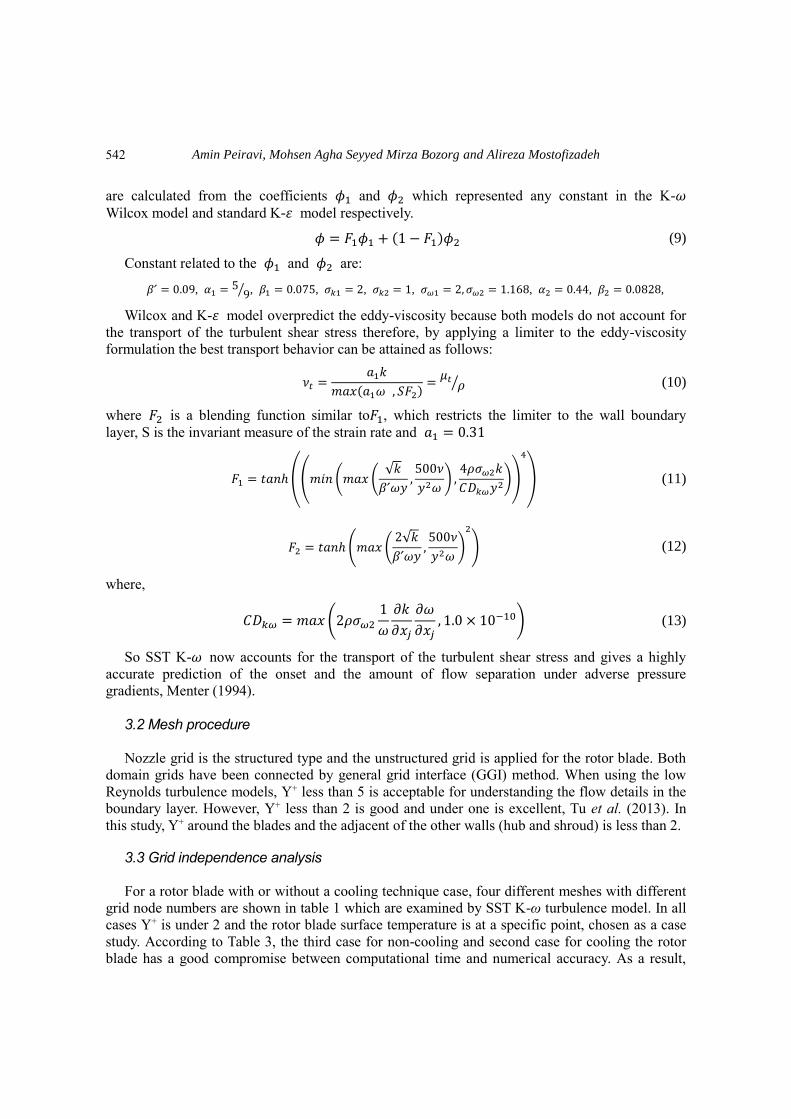
Fig. 4 Comparison between numerical and experimental local Sherwood number on concave surface
along jets center line
bar. Engine’s mass flow and rotational speed are 24.336 Kg/s and 16640 rpm respectively. The air
ideal gas is chosen as inlet gas with 𝐶𝑝 =1148 J⁄ (Kg.K) and Sutherland’s formula is exerted for
relating dynamic viscosity to temperature. Tip clearance is considered 0.5% of the rotor span
length and cooling air boundary condition is a mass flow inlet which 0.5% of compressor’s airflow
(0.5% of 24.336 Kg/s) with the temperature of 675K deliver to 75 rotor blades and enters the rotor
from plenum inlet at the blade’s hub to feeds cooling jets. Nozzle’s domain has been connected to
the rotor’s domain by an interface boundary condition.
3.5 Comparisons with available experimental data
For validating the capability of different turbulence models in order to explain the flow details
and heat transfer in the current study, an experimental investigation which has been performed by
Hong et al. (2008) is used as model verification. The impingement cooling in the rotating duct is
selected as a case study. Computations are done with three different turbulent models, K-𝜀 model,
K-𝜔 model and SST K-𝜔 model and the values of Sherwood spanwise length at centerline is
compared with the experimental data. Sherwood and the Nusselt numbers are analogous and they
are equal in study by Goldstein and Cho (1995). Although K-𝜀 model exhibited a good prediction
of flow and heat/mass transfer behavior compared to the K-𝜔 model in this study, SST K-𝜔 was
the best model with the maximum relative error of 14.0% for this reason, SST K-𝜔 model is
exerted in the current study. Geometrical details and operating conditions are available in Hong et
al. (2008).
4. Results and discussions
4.1 Surveying temperature distribution in non-cooling condition
Inspection of contours and the charts for temperature distribution show that there are two main
544

Numerical simulation and investigation of jet impingement cooling heat transfer for the rotor blade
Fig. 5 Generated vortex on suction surface
critical regions in the rotor blade. One is the leading edge from hub to tip which due to the
formation of stagnation point, heat transfer is considerable on this area and parameters such as free
shear turbulence intensity, unsteady wakes, surface roughness and geometry impress on heat
transfer in this region, Froessling (1958). Another thermal stress is near the midspan length
towards the blade tip on the suction surface. These thermal stresses are more considerable on the
blade tip due to the existence of tip clearance vortices which are induced by pressure differences at
the blade tip. Fig.5 shows temperature distribution on the rotor blade surface in existence of
streamlines. As it shows, these vortices have started from the leading edge on the pressure side and
have continued to the trailing edge towards the suction side. As they move from the leading edge
to the trailing edge they become larger and embrace more of the rotor blade’s surface area. These
vortices consist of high main flow gas temperatures and cause severe flow mixing and turbulence.
This increases the heat transfer at the suction side of the rotor blade’s tip, Metzger and Rued
(1989). Tmax on the rotor blade surface is 1230K.
4.2 Surveying temperature distribution in mon-cooling condition
Blockage at the end of plenum increases the static pressure. In addition, rotation cause Coriolis
forces (2ω⃑⃑ × νr⃑⃑ ⃑)and centrifugal forces (ω⃑⃑ × ω⃑⃑ × r ), which both have a direct effect on the
momentum equation and cause radial pressure gradient in plenum, Greitzer et al. (2007). Thus jet
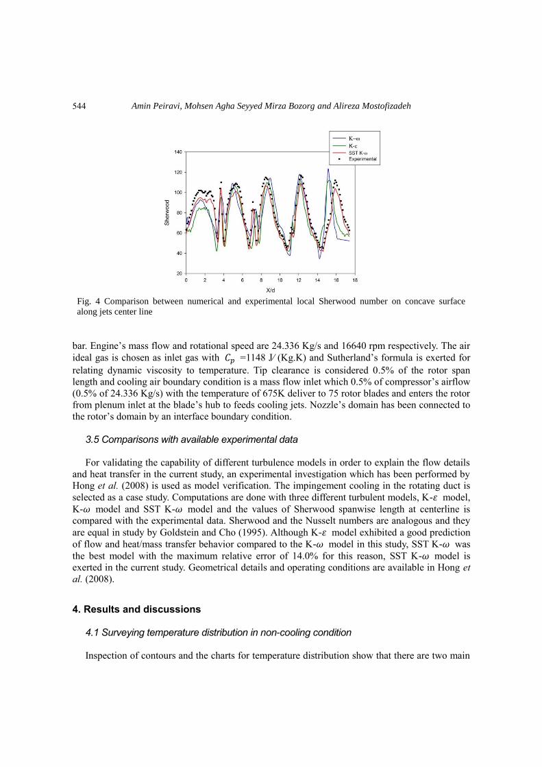
speed increase at the end of the plenum (Vmax=265.2 m/s), Fig. 6 shows jets velocity profile at the
center of the jet holes plate; location 0.0 is nearest to hub and 1.0 is nearest to tip.
545
Amin Peiravi, Mohsen Agha Seyyed Mirza Bozorg and Alireza Mostofizadeh
Fig. 6 Jet velocity profiles at the center plane of jets
Table 4 Jets’ Reynolds number (1 is the nearest jet to the hub)
Jet No. Reynolds Number
1 2420
2 2501
3 2715
4 2767
5 2881
6 3013
7 3169
8 3350
9 3385
10 3514
11 3807
12 4095
13 4196
14 4531
15 4723
Fig. 7 shows the temperature contour on the rotor blade suction and the pressure surface in
existence of impingement cooling. Fig. 8 shows the temperature distribution at 30%, 50%, 70%,
80% and 90% of rotor blade span in cooling and no cooling condition which Tmaxis the nozzle’s
inlet temperature (1250 K). As observed, in non-cooling condition, moving towards the blade tip
the temperature increases. Subsequently, in the existence of impingement cooling the temperature
decreases. Firstly, the reason for this phenomenon is the increase in jets momentum. As they reach
towards the blade tip, the high-speed flow raises the local and the average heat transfer near the
tip. Another reason is the mixture of flows that are between the free spaces of the plenum and the
546

Numerical simulation and investigation of jet impingement cooling heat transfer for the rotor blade
Fig. 7 Temperature distribution on suction and pressure surface in existence of impingement cooling
(a) 30% of the rotor span (b) 50% of the rotor span
(c) 70% of the rotor span (d) 80% of the rotor span
Fig. 8 Rotor temperature comparison for cooling and non-cooling case in different spans
547

Amin Peiravi, Mohsen Agha Seyyed Mirza Bozorg and Alireza Mostofizadeh
(e) 90% of the rotor span
Fig. 8 Continued
Fig. 9 Coolant streamlines from jets to T.E slot
blade. This mixture reaches the greatest amount of turbulence near the blade tip. This happens
because initial jets’ flow that is adjacent to the hub tends to leave the blade through the slot, near
the tip as near as possible because of rotation effects. Simultaneously, the jets nearby the tip tend
to show the same characteristic, but all the flows cannot eject through the trailing edge slot near
the tip chronologically so flow mixture in the space between blade and plenum adjoining to the tip
is greater and consequently convection heat transfer is more.
4.3 Cooling effects on rotor loss
For the mixture of the coolant with the main flow, loss in blades which are exerted on cooling
548
Numerical simulation and investigation of jet impingement cooling heat transfer for the rotor blade
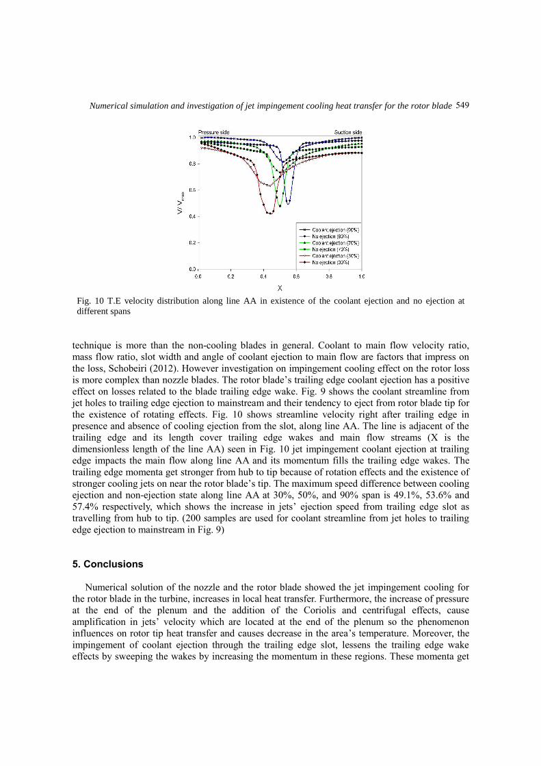
Fig. 10 T.E velocity distribution along line AA in existence of the coolant ejection and no ejection at
different spans
technique is more than the non-cooling blades in general. Coolant to main flow velocity ratio,
mass flow ratio, slot width and angle of coolant ejection to main flow are factors that impress on
the loss, Schobeiri (2012). However investigation on impingement cooling effect on the rotor loss
is more complex than nozzle blades. The rotor blade’s trailing edge coolant ejection has a positive
effect on losses related to the blade trailing edge wake. Fig. 9 shows the coolant streamline from
jet holes to trailing edge ejection to mainstream and their tendency to eject from rotor blade tip for
the existence of rotating effects. Fig. 10 shows streamline velocity right after trailing edge in
presence and absence of cooling ejection from the slot, along line AA. The line is adjacent of the
trailing edge and its length cover trailing edge wakes and main flow streams (X is the
dimensionless length of the line AA) seen in Fig. 10 jet impingement coolant ejection at trailing
edge impacts the main flow along line AA and its momentum fills the trailing edge wakes. The
trailing edge momenta get stronger from hub to tip because of rotation effects and the existence of
stronger cooling jets on near the rotor blade’s tip. The maximum speed difference between cooling
ejection and non-ejection state along line AA at 30%, 50%, and 90% span is 49.1%, 53.6% and
57.4% respectively, which shows the increase in jets’ ejection speed from trailing edge slot as
travelling from hub to tip. (200 samples are used for coolant streamline from jet holes to trailing
edge ejection to mainstream in Fig. 9)
5. Conclusions
Numerical solution of the nozzle and the rotor blade showed the jet impingement cooling for
the rotor blade in the turbine, increases in local heat transfer. Furthermore, the increase of pressure
at the end of the plenum and the addition of the Coriolis and centrifugal effects, cause
amplification in jets’ velocity which are located at the end of the plenum so the phenomenon
influences on rotor tip heat transfer and causes decrease in the area’s temperature. Moreover, the
impingement of coolant ejection through the trailing edge slot, lessens the trailing edge wake
effects by sweeping the wakes by increasing the momentum in these regions. These momenta get
549
Amin Peiravi, Mohsen Agha Seyyed Mirza Bozorg and Alireza Mostofizadeh
stronger at the rotor tip due to the existence of the rotational effects and their declination to leave
the blade through trailing edge slot, near the tip.
References
Bardina, J., Huang, P. and Coakley, T. (1997), “Turbulence modeling validation”, Proceedings of the 28th
Fluid Dynamics Conference, Snowmass Village, Colorado, U.S.A., June-July.
Bunker, R.S. and Metzger, D.E. (1990), “Local heat transfer in internally cooled turbine airfoil leading edge
regions: Part I—impingement cooling without film coolant extraction”, J. Turbomachine., 112(3), 451-
458. https://doi.org/10.1115/1.2927680.
Chupp, R.E., Helms, H.E., McFadden, P.W. and Brown, T.R. (1969), “Evaluation of internal heat-transfer
coefficients for impingement-cooled turbine airfoils”, J. Aircraft, 6(3), 203-208.
https://doi.org/10.2514/3.44036.
Dong, L.L., Leung, C.W. and Cheung, C.S. (2002), “Heat transfer characteristics of premixed butane/air
flame jet impinging on an inclined flat surface”, Heat Mass Transfer, 39(1), 19-26.
https://doi.org/10.1007/s00231-001-0288-1.
Ekkad, S., Huang, Y. and Han, J.C. (2000), “Impingement heat transfer measurements under an array of
inclined jets”, J. Thermophys. Heat Tr, 14(2), 286-288. https://doi.org/10.2514/2.6524.
Froessling, N. (1958), “Evaporation, heat transfer, and velocity distribution in two-dimensional and
rotationally symmetrical laminar boundary-layer flow”, NACA-TM-14, NACA Technical Memorandum,
U.S.A.
Gau, C. and Chung, C. (1991). “Surface curvature effect on slot-air-jet impingement cooling flow and heat
transfer process”, J. Heat Trans., 113(4), 858-864. https://doi.org/10.1115/1.2911214.
Goldstein, R.J. and Cho, H.H. (1995), “A review of mass transfer measurements using naphthalene
sublimation”, Exp. Therm. Fluid Sci., 10(4), 416-434. https://doi.org/10.1016/0894-1777(94)00071-F.
Greitzer, E.M., Tan, C.S. and Graf, M.B. (2007), Internal Flow: Concepts and Applications, Cambridge
University Press, Cambridge, U.K.
Hong, S.K., Lee, D.H. and Cho, H.H. (2008), “Heat/mass transfer measurement on concave surface in
rotating jet impingement”, J. Mech. Sci. Technol., 22(10), 1952-1958.
https://doi.org/10.1007/s12206-008-0738-5.
Hrycak, P. (1981), “Heat transfer from a row of impinging jets to concave cylindrical surfaces”, Int. J. Heat
Mass Tran., 24(3), 407-419. https://doi.org/10.1016/0017-9310(81)90048-X.
Hwang, J.J. and Cheng, C.S. (2001), “Impingement cooling in triangular ducts using an array of side-entry
wall jets”, Int. J. Heat Mass Tran., 44(5), 1053-1063. https://doi.org/10.1016/S0017-9310(00)00141-1.
Ibrahim, M.B., Kochuparambil, B.J., Ekkad, S.V. and Simon, T.W. (2005), “CFD for jet impingement heat
transfer with single jets and arrays”, Proceedings of the ASME Turbo Expo 2005: Power for Land, Sea,
and Air, Reno, Nevada, U.S.A., June.
Jia, R., Rokni, M. amd Sundén, B. (2002), “Numerical assessment of different turbulence models for slot jet
impinging on flat and concave surfaces”, Proceedings of the ASME Turbo Expo2020: Power for Land,
Sea, and Air, Amsterdam, The Netherlands, June.
Li, H.L., Chiang, H.W.D. and Hsu, C.N. (2011), “Jet impingement and forced convection cooling
experimental study in rotating turbine blades”, Int. J. Turbo Jet Eng., 28(2), 147-158.
https://doi.org/10.1515/tjj.2011.015.
Menter, F.R. (1994), “Two-equation eddy-viscosity turbulence models for engineering applications”, AIAA
J., 32(8), 1598-1605. https://doi.org/10.2514/3.12149.
Metzger, D.E. and Rued, K. (1989), “The influence of turbine clearance gap leakage on passage velocity and
heat transfer near blade tips: Part I—sink flow effects on blade pressure side”, J. Turbomach., 111(3), 284-
292. https://doi.org/10.1115/1.3262267.
Saeed, F. (2008), “Numerical simulation of surface heat transfer from an array of hot-air jets”, J. Aircraft,
45(2), 700-714. https://doi.org/10.2514/1.33489.
550

Numerical simulation and investigation of jet impingement cooling heat transfer for the rotor blade
Schobeiri, M. (2012), Turbomachinery Flow Physics and Dynamic Performance, Springer, Berlin, Germany.
Stevens, J. and Webb, B.W. (1991), “The effect of inclination on local heat transfer under an axisymmetric,
free liquid jet”, Int. J. Heat Mass Trans., 34(4-5), 1227-1236.
https://doi.org/10.1016/0017-9310(91)90031-9.
Tabakoff, W. and Clevenger, W. (1972), “Gas turbine blade heat transfer augmentation by impingement of
air jets having various configurations”, J. Eng. Power, 94(1), 51-58. https://doi.org/10.1115/1.3445620.
Tu, J., Yeoh, G.H. and Liu, C. (2013), Computational Fluid Dynamics, Butterworth-Heinemann,
Amsterdam, The Netherlands.
CC
551