Embed Size (px)
Citation preview

Document reference NPS/003/025 Document Type: Code of Practice
Version:- 1.0 Date of Issue:- September 2015 Page 1 of 74
NPS/003/025 – Technical Specification for Fault Throwers
1. Purpose
This document is the technical specification for Fault Throwers for use on the electrical networks of Northern Powergrid.
This document supersedes the following documents, all copies of which should be removed from circulation.
Ref Version Title
D/PRC/S/203 Part 2 Sections & Clauses Relating to Fault Throwing Switches.
Current 66kV (72.5kV) Disconnectors. Switch Disconnectors, Earth Switches and Fault Throwing Switches.
D/PRC/S/203 Part 3 Sections & Clauses Relating to Fault Throwing Switches.
Current 132kV (145kV) Disconnectors. Switch Disconnectors, Earth Switches and Fault Throwing Switches.
YEDL 33kV Fault Thrower Enquiry MASTER DOCUMENT
Current YEDL 33kV Fault Thrower Enquiry MASTER DOCUMENT
NEDL PEP Schedule 3 spec for fault throwers Current Fault Throwers
2. Scope
This specification covers the technical requirements for Fault Throwers for use on the Northern Powergrid distribution network. It will be necessary to consider and include any project specific requirements as detailed in Appendix 1, Schedule of Requirements.

Document reference NPS/003/025 Document Type: Code of Practice
Version:- 1.0 Date of Issue:- September 2015 Page 2 of 74
Contents
1. Purpose ........................................................................................................................................................... 1
2. Scope ............................................................................................................................................................... 1
3. Technical Requirements .................................................................................................................................. 3
3.1. Overview ......................................................................................................................................................... 3
3.2. Technical Specification .................................................................................................................................... 3
3.2.1. Overall ............................................................................................................................................................. 3
3.2.2. Fault Throwers for Use On Systems Up To 33kV Nominal Voltage ................................................................... 4
3.2.3. Fault Throwers for Use on Systems with 66kV or 132kV Nominal Voltage ....................................................... 6
4. References ...................................................................................................................................................... 7
4.1. External Documentation.................................................................................................................................. 7
4.2. Internal documentation .................................................................................................................................. 7
4.3. Key amendments from Previous Version ............................................................. Error! Bookmark not defined.
5. Definitions ....................................................................................................................................................... 7
6. Authority for issue ........................................................................................................................................... 8
6.1. CDS Assurance ................................................................................................................................................. 8
6.2. Author ............................................................................................................................................................. 8
6.3. Technical Assurance ........................................................................................................................................ 8
6.4. Approval .......................................................................................................................................................... 8
6.5. Authorisation .................................................................................................................................................. 8
Appendix 1 –Schedule of Requirements .......................................................................................................................... 9
Appendix 2 – Summary of Technical Performance of Products Offered ......................................................................... 10
Appendix 3 - Declaration of Conformance with this Specification (NPS/003/025) ......................................................... 11
Appendix 4 - Declaration of Conformance with ENA Technical Specification 41-36 or 41-37 ......................................... 13
Appendix 4a – Applicable for 11kV to 33kV Fault Throwers ........................................................................................... 14
Appendix 4b – Applicable for 66kV and 132kV Fault Throwers ...................................................................................... 37

Document reference NPS/003/025 Document Type: Code of Practice
Version:- 1.0 Date of Issue:- September 2015 Page 3 of 74
3. Technical Requirements
3.1. Overview
The requirement is for fault throwers that can be used on the Northern Powergrid distribution network.
Fault throwers are devices used to connect one phase to earth, deliberately causing high levels of current to flow and subsequently causing the upstream protection devices to operate. Fault Throwers shall be suitable for multiple operations, shall maximise the maintenance intervals and shall minimise any maintenance requirements.
Fault thrower ratings are detailed in the sections below and in Appendix 1. The specified ratings shall apply with a 3 second duration of rated short time withstand current and rated short-circuit making current of 2.7 times the rated short time withstand current.
Fault throwers are required for use in different arrangements of substation plant and equipment, including:
Pedestal or post mounted units where the HV connection is made via separable cable connectors, or
Pedestal or post mounted units where the HV connection is made via overhead, busbar, or busbar dropper connections.
3.2. Technical Specification
3.2.1. Overall
Unless varied by this Northern Powergrid specification, fault throwers shall comply generally with the appropriate requirements of the Energy Network Association Technical Specifications (ENA TS) 41-36 or 41-37 as appropriate for the network voltage and for the design of the fault thrower.
Fault throwers will preferably possess an ENA Notice of Conformity.
It is preferred that the fault thrower is capable of being operated and reset remotely but shall in all cases provide remote indication to the substation SCADA system.
Where the fault thrower utilises an exposed high voltage operating arm it shall, when in the ‘open’ position, meet the isolating requirements specified for a disconnector.
Although fault throwers may be used in outdoor or indoor situations they shall be designed, constructed and tested for outdoor use.
Depending upon the schedule of requirements defined in Appendix 1, fault throwers will be accepted either with exposed HV components or earth-screened HV components throughout.
Where exposed connections are required these will be specified in Appendix 1. Ground mounted fault throwers with unscreened HV primary conductors are not acceptable.
Appendix 1 shall be completed by Northern Powergrid and shall state the project specific requirements including the required duties for the unit(s).
Appendices 2, 3 and 4 shall be completed by the manufacturer based on the products offered to meet the project specific requirements;
Appendix 2 is a declaration of technical performance for the fault thrower. This shall be completed for each type of fault thrower offered.
Appendix 3 is a declaration of conformance with this specification (NPS/003/025).
Appendix 4 is a declaration of conformance with ENA technical specification ENA TS 41-36 or 41-37.

Document reference NPS/003/025 Document Type: Code of Practice
Version:- 1.0 Date of Issue:- September 2015 Page 4 of 74
3.2.2. Fault Throwers for Use On Systems Up To 33kV Nominal Voltage
Closing times shall not exceed 400ms.
The following variations, additions or clarifications to ENATS 41-36 are referenced to the clause numbers used in ENATS 41-36.
ENATS 41-36 Part 1 Common Clauses
1.2.1 Normal Service Conditions All fault throwers shall be in accordance with clause 1.2.1.2 Outdoor switchgear and control gear.
1.4.2 Rated Insulation Level The lightning impulse level for 12kV rated voltage shall be: 95kV common value and 110kV across the isolating distance.
1.4.5 Values of Rated Short Time Withstand Current Unless varied in the schedule of requirements in Appendix 1, the values of rated short time withstand current that are applicable to the primary conductor circuit and to the earthing circuit shall meet the requirements for time constants of both 45ms and 120ms stated in the table below:
Nominal Network Voltage (kV) Rated Short Time Withstand Current (kA for 3 secs)
Time constant 45ms Time constant 120ms
11kV 25kA 16kA
20kV 20kA 12.5kA
33kV 31.5kA 20kA
1.4.8 Rated Supply Voltage of Closing and Opening Devices and Aux Circuits The values shall be as specified in Appendix 1.
1.5.1 Requirements for Liquids Oil filled equipment is not permitted.
1.5.102.102 Foundation Arrangements Foundations arrangements shall be as specified in the schedule of requirements in Appendix 1.
1.5.102.103 Transformer Mounting Arrangements The unit substation design shall not apply to fault throwers.
1.5.103.1.101 Cable Compartments. The preferred arrangement shall utilise HV cable connections via separable connectors. Where utilised, these connectors shall be DIN type (non load break) disconnectable elbows, tested in accordance with BS7888, or equivalent.
These connections shall be enclosed by a substantial metal cover that shall provide mechanical protection for the connectors. This cover shall be well ventilated, but shall provide protection to class IP3XB of IEC 60529.
1.5.0.4.5 Facilities for checking and testing Clauses 1.5.0.4.5.1.1 (c), (d) and (e) shall not apply. Clauses 1.5.0.4.5.2 (b) and (c) shall not apply. Clause 1.5.0.4.7 shall not apply.

Document reference NPS/003/025 Document Type: Code of Practice
Version:- 1.0 Date of Issue:- September 2015 Page 5 of 74
ENATS 41-36 Part 2 Additional Clauses For Metal Enclosed Circuit Breakers Clauses and requirements relating to making load current, breaking load current, breaking fault current or auto recluse duty shall not apply.
2.4.106 Rated out-of-Phase Making and Breaking An out-of-phase making rating is required.
2.4.111 Fault thrower circuit breakers shall be classified class E2 (no maintenance of interrupting parts of the main circuit during its expected operating life and only minimal maintenance of its other parts).
ENATS 41-36 Part 3 Additional Clauses For Metal Enclosed Switches Clauses and requirements relating to making or breaking load current shall not apply.
3.5.3 Earthing – shall not apply.
3.5.11 Interlocking Devices – shall not apply.
ENATS 41-36 Part 4 Additional Clauses For Metal Enclosed Switch Fuse Combinations Switch fuse combinations shall not be permitted.
ENATS 41-36 Part 5 Ring Main Equipment Ring Main Equipment arrangements shall not be permitted.
ENATS 41-36 Part 6 Overhead Conductor Connected Clauses and requirements relating to making or breaking load current shall not apply.
6.5.5.1 General 6.5.7 Integral Operating Rods Manual operation via an operating rod shall not be provided. 6.5.11 Interlocking Devices
ENATS 41-36 Part 7 Pole Mounted Enclosed Switchgear Clauses and requirements relating to making or breaking load current shall not apply.
7.1.3.1 Manual Operation – via an operating rod shall not be permitted.
7.1.3.2 Power 7.1.4 Auxiliary Supplies shall be supplied by local substation supplies specified in Appendix 1. 7.1.5 Auxiliary Transformer
7.2 Auto-Reclosing Circuit Breakers – does not apply.
7.3.1 General A fault thrower having the capability to close ten times at the rated short-circuit making current will be regarded as the absolute minimum capability.
7.3.2 Control & Indication - Clauses (d) and (e) shall not apply.
7.4 Sectionalisers – shall not apply.
ENATS 41-36 Part 8 Overhead Connected Fuses & Links Part 8 shall not apply.
ENATS 41-36 Part 9 Additional Clauses for 36kV Fault Throwing Switches. 7.3.1 General A fault thrower having the capability to close ten times at the rated short-circuit making current will be regarded as the absolute minimum capability.

Document reference NPS/003/025 Document Type: Code of Practice
Version:- 1.0 Date of Issue:- September 2015 Page 6 of 74
3.2.3. Fault Throwers for Use on Systems with 66kV or 132kV Nominal Voltage
Closing times shall not exceed 400ms.
The following variations, additions or clarifications to ENATS 41-37 are referenced to the numbering system used in ENATS 41-37.
ENATS 41-37 Part 1 – Common Clauses
4.1 Rated Normal Current This clause shall not apply. 4.5 Values of Rated Short Time Withstand Current Unless varied in the schedule of requirements in Appendix 1, the values of rated short time withstand current that are applicable to the primary conductor circuit and to the earthing circuit shall meet the requirements for time constants of both 45ms and 120ms stated in the table below:
Nominal Network Voltage (kV) Rated Short Time Withstand Current (kA for 3 secs)
Time constant 45ms Time constant 120ms
66kV 31.5kA 20kA
132kV 40kA 25kA
5.8.101 Loss Of Control Supply Loss of the dc opening supply shall NOT inhibit closing circuits.
ENATS 41-37 Part 2 – GIS Clauses, or parts of clauses, relating to the tripping functions or interruption of current shall not apply. Clauses, or parts of clauses, relating to the short circuit making duties and out of phase conditions shall apply.
ENATS 41-37 Part 3 – Circuit Breakers Clauses, or parts of clauses, relating to the tripping functions or interruption of current shall not apply. Clauses, or parts of clauses, relating to the short circuit making duties and out of phase conditions shall apply.
5.5.102 Operating Systems Interlock Operating systems shall be arranged to prevent a close operation if sufficient energy is not available to complete the close operation.
5.5.103 Independent Drive Mechanisms This clause shall not apply.
5.11.101 Mechanical Key Interlocking This clause shall not apply.
ENATS 41-37 Part 4 – Disconnectors and Earthing Switches Clauses, or parts of clauses, relating to the tripping functions or interruption of current shall not apply. Clauses, or parts of clauses, relating to the short circuit making duties and out of phase conditions shall apply.
5.11.101 Mechanical Key Interlocking This clause shall not apply.

Document reference NPS/003/025 Document Type: Code of Practice
Version:- 1.0 Date of Issue:- September 2015 Page 7 of 74
4. References
4.1. External Documentation
Reference Title Version and date
ENATS 41-36 Distribution Switchgear for Service up to 36kV (Cable and Overhead Conductor Connected)
Issue 3 2012
ENATS 41-37 Part 1 Switchgear for use on 66 kV to 132 kV distribution systems Part 1 Common clauses
Issue 2 2014
ENATS 41-37 Part 2 Switchgear for use on 66 kV to 132 kV distribution systems Part 2 Gas-insulated metal-enclosed switchgear
Issue 2 2014
ENATS 41-37 Part 3 Switchgear for use on 66 kV to 132 kV distribution systems Part 3 Alternating current circuit-breakers
Issue 2 2014
ENATS 41-37 Part 4 Switchgear for use on 66 kV to 132 kV distribution systems Part 4 Disconnectors and earthing switches
Issue 2 2014
BS EN 62271-1:2008+A1:2011
High-voltage switchgear and control gear. Common specifications
2011
BS EN 62271-100:2009+A1:2012
High-voltage switchgear and control gear. Alternating current circuit-breakers
2012
BS EN 62271-102:2002+A2:2013
High-voltage switchgear and control gear. Alternating current disconnectors and earthing switches
2013
BS EN 62271-103:2011
High-voltage switchgear and control gear. Switches for rated voltages above 1 kV up to and including 52 kV
2011
BS EN 62271-203:2012
High-voltage switchgear and control gear. Gas-insulated metal-enclosed switchgear for rated voltages above 52 kV
2012
BS 7888-4.1:2006+A1:2008
Test requirements on accessories for use on power cables of rated voltage from 3, 6/6(7, 2) kV up to 20, 8/36(42) kV. Cables with extruded insulation.
2008
BS EN 60529:1992+A2:2013
Degrees of protection provided by enclosures (IP code) 2013
BS EN 60694:1997
Common specifications for high-voltage switchgear and control gear standards
1997
4.2. Internal documentation
Reference Title Version and date
IMP/001/909 Code of Practice for Distribution System Parameters Version 3 2014
5. Definitions
Term Definition
Rated short time withstand current The r.m.s. value of the current which the switchgear can carry in the closed position for a period of 3 seconds.
Rated short-circuit making current The short-circuit current that the switchgear can withstand as it is closing where the act of closing initiates the fault and is expressed in maximum peak value.
SCADA Supervisory control and data acquisition

Document reference NPS/003/025 Document Type: Code of Practice
Version:- 1.0 Date of Issue:- September 2015 Page 8 of 74
6. Authority for issue
6.1. CDS Assurance
I sign to confirm that I have completed and checked this document and I am satisfied with its content and submit it for approval and authorisation.
Sign Date
Sarah Phillips CDS Administrator Sarah Phillips 02/09/15
6.2. Author
I sign to confirm that I have completed and checked this document and I am satisfied with its content and submit it for approval and authorisation.
Review Period - This document should be reviewed within the following time period.
Standard CDS review of 3 years
Non Standard Review Period & Reason
Yes Period: Reason:
Sign Date
Joseph Helm Senior Policy and Standards Engineer
Joseph Helm 02/09/15
6.3. Technical Assurance
I sign to confirm that I am satisfied with all aspects of the content and preparation of this document and submit it for approval and authorisation.
Sign Date
David Blackledge Senior Policy and Standards Engineer
David Blackledge 02/09/15
6.4. Approval
Approval is granted for publication of this document.
Sign Date
Chris Holdsworth Policy and Standards Manager
Chris Holdsworth 02/09/15
6.5. Authorisation
Authorisation is granted for publication of this document.
Sign Date
Mark Nicholson Head of System Strategy Mark Nicholson 04/09/15

Document reference NPS/003/025 Document Type: Code of Practice
Version:- 1.0 Date of Issue:- September 2015 Page 9 of 74
Appendix 1 –Schedule of Requirements
Table to be completed by Northern Powergrid to meet the project specific requirements.
Criteria Requirement If none please state ‘NONE’, where applicable.
Network Voltage Specified as nominal phase to phase voltage of electrical network.
Fault Current Default is as specified in the body text of NPS/003/025
Cable Connected (no exposed primary conductors) Specify cable size and type and cable support arrangement required or Busbar/Overhead connected Specify conductor size & type and connection type
Auxiliary Supply Voltage Rated supply voltage of closing, opening and auxiliary circuits
Physical constraints Including height, width, depth, weight, etc.
Foundation/support/mounting arrangements
Other
Document reference NPS/003/025 Document Type: Code of Practice
Version:- 1.0 Date of Issue:- September 2015 Page 10 of 74
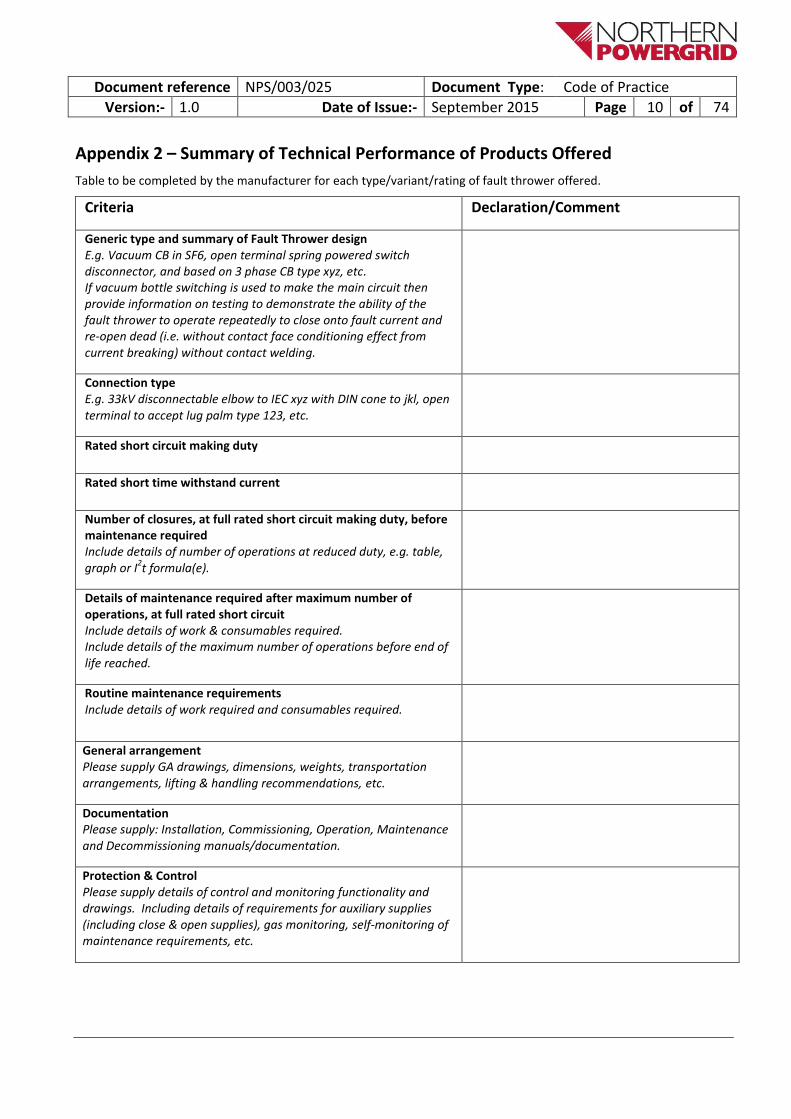
Appendix 2 – Summary of Technical Performance of Products Offered
Table to be completed by the manufacturer for each type/variant/rating of fault thrower offered.
Criteria Declaration/Comment
Generic type and summary of Fault Thrower design E.g. Vacuum CB in SF6, open terminal spring powered switch disconnector, and based on 3 phase CB type xyz, etc. If vacuum bottle switching is used to make the main circuit then provide information on testing to demonstrate the ability of the fault thrower to operate repeatedly to close onto fault current and re-open dead (i.e. without contact face conditioning effect from current breaking) without contact welding.
Connection type E.g. 33kV disconnectable elbow to IEC xyz with DIN cone to jkl, open terminal to accept lug palm type 123, etc.
Rated short circuit making duty
Rated short time withstand current
Number of closures, at full rated short circuit making duty, before maintenance required Include details of number of operations at reduced duty, e.g. table, graph or I
2t formula(e).
Details of maintenance required after maximum number of operations, at full rated short circuit Include details of work & consumables required. Include details of the maximum number of operations before end of life reached.
Routine maintenance requirements Include details of work required and consumables required.
General arrangement Please supply GA drawings, dimensions, weights, transportation arrangements, lifting & handling recommendations, etc.
Documentation Please supply: Installation, Commissioning, Operation, Maintenance and Decommissioning manuals/documentation.
Protection & Control Please supply details of control and monitoring functionality and drawings. Including details of requirements for auxiliary supplies (including close & open supplies), gas monitoring, self-monitoring of maintenance requirements, etc.

Document reference NPS/003/025 Document Type: Code of Practice
Version:- 1.0 Date of Issue:- September 2015 Page 11 of 74
Appendix 3 - Declaration of Conformance with this Specification (NPS/003/025)
Table to be completed by the manufacturer for each type/variant/rating of fault thrower offered.
NPS Section Requirement Declaration/Comment
3.1
3 second rated duration of short time withstand current.
3.1
Rated short circuit making of 2.7 times rated short time withstand current.
3.1 Pedestal or post mounted units allowing the HV connection to be made either via;
separable cable connectors, Pedestal or
overhead, busbar, or busbar dropper connections.
3.2.1
ENA Notice of Conformity.
3.2.1 Any exposed high voltage operating arm shall, when in the ‘open’ position, meet the isolating requirements specified for a disconnector.
3.2.1 Designed, constructed and tested for outdoor use.
3.2.1 In the case of ground mounted units all primary conductors shall be screened.
3.2.2
Closing times shall not exceed 400ms.
3.2.2 Lightning impulse level for 12kV rated voltage shall be: 95kV common value and 110kV across the isolating distance.
3.2.2 Confirm Rated Short Time Withstand Current
3.2.2 Oil filled equipment is not permitted.
3.2.2 HV cable connections via separable connectors. Where utilised, these connectors shall be DIN type (non load break) disconnectable elbows, tested in accordance with BS7888, or equivalent.

Document reference NPS/003/025 Document Type: Code of Practice
Version:- 1.0 Date of Issue:- September 2015 Page 12 of 74
NPS Section Requirement Declaration/Comment
3.2.2 A metal cover shall provide mechanical protection for the connectors. This cover shall be well ventilated, but shall provide protection to class IP3XB of IEC 60529.
3.2.2 Confirm out-of-phase making rating.
3.2.2 Manual operation via an operating rod shall not be provided.
3.2.2 Fault thrower circuit breakers shall be classified class E2.
3.2.2 Confirm a minimum capability of ten close operations at the rated short-circuit making current.
3.2.3 Confirm Rated Short Time Withstand Current
3.2.3 Loss of the dc opening supply shall NOT inhibit closing circuits.
3.2.3 Operating systems shall be arranged to prevent a close operation if sufficient energy is not available to complete the close operation.

Document reference NPS/003/025 Document Type: Code of Practice
Version:- 1.0 Date of Issue:- September 2015 Page 13 of 74
Appendix 4 - Declaration of Conformance with ENA Technical Specification 41-36 or 41-37
The self-certification conformance declaration’s from the following ENA TS have been added to this Appendix 4 of this specification: -
Explanatory comments must be added for ALL clauses, regardless of conformance code.
Appendix 4a – Applicable for 11kV to 33kV Fault Throwers
ENA TS 41-36 Distribution Switchgear for Service up to 36kV Part 1 – Common Clauses.
ENA TS 41-36 Distribution Switchgear for Service up to 36kV Part 9 – Fault Throwing Switches.
ENA TS 41-36 Distribution Switchgear for Service up to 36kV Part 10 – Protection, Instrumentation and Metering Equipment.
Appendix 4b – Applicable for 66kV and 132kV Fault Throwers
ENA TS 41-37 Switchgear for use on 66kV to 132kV Distribution Systems – Common Clauses.
ENA TS 41-37 Switchgear for use on 66kV to 132kV Distribution Systems – GIS Switchgear.
ENA TS 41-37 Switchgear for use on 66kV to 132kV Distribution Systems – Circuit Breakers.
ENA TS 41-37 Switchgear for use on 66kV to 132kV Distribution Systems – Disconnectors and Earthing Switches.
The supplier shall complete all clauses relevant to the product being offered. Where the clause is not applicable this should be documented (i.e. N/A).

Document reference NPS/003/025 Document Type: Code of Practice
Version:- 1.0 Date of Issue:- September 2015 Page 14 of 74
Appendix 4a – Applicable for 11kV to 33kV Fault Throwers
SELF CERTIFICATION CONFORMANCE DECLARATION PART 1 – COMMON CLAUSES CLAUSE BY CLAUSE CONFORMANCE WITH ENATS 41-36 – Part 1 Switchgear covered by ENATS 41-36 shall comply with the latest issues of the relevant International and British Standards. ENATS 41-36 is intended to amplify and/or clarify the requirements of those Standards. This check sheet identifies the clauses in ENATS 41-36 - Part 1 and the clauses of the aforementioned Standards relevant to common specifications for high-voltage switchgear and control gear standards. The manufacturer shall declare conformance or otherwise, clause by clause, using the following levels of conformance declaration codes. Conformance declaration codes N/A = Clause is not applicable/appropriate to the product Cs1 = The test conforms fully with the requirements of this clause Cs2 = The test conforms partially with the requirements of this clause Cs3 = The test does not conform to the requirements of this clause Cs4 = Test not performed, but alternative evidence/ technical case offered
Manufacturer:
Product Reference: Ratings:
Name: Signature: Date:
Instructions for completion
Explanatory comments must be added for ALL clauses, regardless of conformance code.
Prefix each remark with the relevant ‘I EC’ or ‘ENATS’ as appropriate

Document reference NPS/003/025 Document Type: Code of Practice
Version:- 1.0 Date of Issue:- September 2015 Page 15 of 74
IEC 60694, IEC 62271-200 ENATS 41-36
Clause / Sub-clause
Re
qu
ire
me
nt
Co
nfo
rman
ce
cod
e
ENA
TS 4
1-3
6 -
Par
t 1
Cla
use
/
Sub
- cl
ause
Re
qu
ire
me
nt
Co
nfo
rman
ce
cod
e
Re
mar
ks
IEC60694 IEC62271-
200
1 1 General 1.1 General
2 2 Normal and special service conditions
1.2 Normal and special service conditions
1.2.1.1 Class minus 5 indoor
1.2.1.2 Class minus 25 outdoor
1.2.1.2 Class 10 – ice coating
1.2.1.2 Class III – pollution level
1.2.1.2 Influence of solar radiation
3 3 Definitions 1.3 Definitions
4 4 Ratings 1.4 Ratings
4.1 4.1 Rated voltage 1.4.1 Rated voltage
4.2 4.2 Rated insulation level 1.4.2 Rated insulation level
1.4.2.1 Disconnectors (0 bar gauge)
1.4.2.2. Provision for cable tests
4.3 4.3 Rated frequency 1.4.3 Rated frequency
4.4 4.4 Rated normal current and temperature rise
1.4.4 Rated normal current and temperature rise
1.4.4.1 Rated normal current
4.5 4.5 Rated short-time withstand 1.4.5 Rated short-time withstand
4.6 4.6 Rated peak withstand current 1.4.6 Rated peak withstand current
4.7 4.7 Rated duration of short circuit 1.4.7 Rated duration of short circuit
4.8 4.8 Rated supply voltage of closing and opening devices and of auxiliary and control circuits
1.4.8 Rated supply voltage of closing and opening devices and of auxiliary and control circuits

Document reference NPS/003/025 Document Type: Code of Practice
Version:- 1.0 Date of Issue:- September 2015 Page 16 of 74
IEC 60694, IEC 62271-200 ENATS 41-36
Clause / Sub-clause
Re
qu
ire
me
nt
Co
nfo
rman
ce
cod
e
ENA
TS 4
1-3
6 -
Par
t 1
Cla
use
/
Sub
- cl
ause
Re
qu
ire
me
nt
Co
nfo
rman
ce
cod
e
Re
mar
ks
IEC60694 IEC62271-
200
4.9 4.9 Rated supply frequency of closing and opening devices and of auxiliary circuits
1.4.9 Rated supply frequency of closing and opening devices and of auxiliary circuits
4.10 4.10 Rated pressure of compressed gas supply for insulation and/or operation
1.4.10 Rated pressure of compressed gas supply for insulation and/or operation
4.10.1 Rated filling level (of fluid-filled compartments
5.1 5.1 Requirements for liquids 1.5.1 Requirements for liquids
1.5.1 Oil level indication
1.5.1 Drain plugs, indicators, valves
1.5.1 Controlled gasket compression
1.5.1 No communicating bolts
1.5.1 BS 148
1.5.1 Bolt access
1.5.1 Breather design/position (IP3XDW)
5.2 5.2 Requirements for gasses 1.5.2 Requirements for gasses
1.5.2 Gas filling valve
1.5.2 Recycled SF6
5.3 5.3 Earthing of switchgear and control gear
1.5.3 Earthing of switchgear and control gear
1.5.3 Earthing conductor
1.5.3 Earthing terminals.
1.5.3 Earthing conductor coupling

Document reference NPS/003/025 Document Type: Code of Practice
Version:- 1.0 Date of Issue:- September 2015 Page 17 of 74
IEC 60694, IEC 62271-200 ENATS 41-36
Clause / Sub-clause
Re
qu
ire
me
nt
Co
nfo
rman
ce
cod
e
ENA
TS 4
1-3
6 -
Par
t 1
Cla
use
/
Sub
- cl
ause
Re
qu
ire
me
nt
Co
nfo
rman
ce
cod
e
Re
mar
ks
IEC60694 IEC62271-
200
1.5.3 Withdrawable /removable parts earth connection.
1.5.3 Cable sheath earth connection
1.5.3 Relay/instrument case earthing
1.5.3 Specific means for earthing
1.5.3 Frame-earth busbar protection
5.4 5.4 Auxiliary and control equipment 1.5.4 Auxiliary and control equipment
1.5.4.1.3 Degrees of protection – LV terminals
1.5.4.4.4.4 ENATS 50-19
1.5.4.4.4.4 Identification
1.5.4.4.5.1 Segregation (>125V).
1.5.4.4.5.1 Interchangeable - identical
1.5.4.4.5.1 Conductor material/size.
1.5.4.4.5.1 HV compartment segregation.
1.5.4.4.5.1 Actuator control/indication
1.5.4.4.5.1 Micro switches
1.5.4.4.5.2 Terminals/terminations reliability 50 breaks
1.5.4.4.5.2 CT terminal blocks – screw clamp with spring (ENATS 50-18 type B)
5.5 5.5 Dependent power operation 1.5.5 Dependent power operation
1.5.5 Positively driven contacts
1.5.5 Movement gap withstand voltage
1.5.5 Maintenance / slow operation

Document reference NPS/003/025 Document Type: Code of Practice
Version:- 1.0 Date of Issue:- September 2015 Page 18 of 74
IEC 60694, IEC 62271-200 ENATS 41-36
Clause / Sub-clause
Re
qu
ire
me
nt
Co
nfo
rman
ce
cod
e
ENA
TS 4
1-3
6 -
Par
t 1
Cla
use
/
Sub
- cl
ause
Re
qu
ire
me
nt
Co
nfo
rman
ce
cod
e
Re
mar
ks
IEC60694 IEC62271-
200
1.5.5 Labelled - maintenance
5.6 5.6 Stored energy operation 1.5.6 Stored energy operation
1.5.6 Sub-clause 1.5.5 applicable plus the following
1.5.6 Main contact movement
1.5.6 Dedicated handle
1.5.6 Handle direction indication
1.5.6 Handle release and stowed
1.5.6 Motor actuator fitting
1.5.6 Motor actuator disconnection
1.5.6 Actuator ‘in step’ (methods a or b)
1.5.6 Manual charging motor-charge
1.5.6 Max/min handle heights
1.5.6 Re-charge closing springs
1.5.6 Spring charge indication
1.5.7 Manual operation
1.5.7 Handles and padlocking accessible from front
1.5.7 Handle storage facilities
5.7 5.7 Independent manual operation 1.5.7.1 Independent manual operation
1.5.7.1 Sub-clause 1.5.6 applicable plus the following
1.5.7.1 Inhibit closing spring charge in closed position

Document reference NPS/003/025 Document Type: Code of Practice
Version:- 1.0 Date of Issue:- September 2015 Page 19 of 74
IEC 60694, IEC 62271-200 ENATS 41-36
Clause / Sub-clause
Re
qu
ire
me
nt
Co
nfo
rman
ce
cod
e
ENA
TS 4
1-3
6 -
Par
t 1
Cla
use
/
Sub
- cl
ause
Re
qu
ire
me
nt
Co
nfo
rman
ce
cod
e
Re
mar
ks
IEC60694 IEC62271-
200
1.5.7.1 No stored energy from Incomplete operation
1.5.7.1 Anti-reflex =>3 secs (manual)
1.5.7.1 Anti-reflex =>3 secs (actuator)
1.5.7.2 Dependent manual operation. - as 1.5.7.1 plus: Inhibit op handle removal
5.8 5.8 Operation of releases 1.5.8 Operation of releases
1.5.8 Local manual release
1.5.8 Operation outside switchroom
1.5.8 No movement of spring charge handle.
5.9 5.9 Low and high-pressure interlocking and monitoring devices
1.5.9 Low and high-pressure interlocking and monitoring devices
1.5.9 Pressure/density gauge/indicator
1.5.9 20°C filling mark
1.5.9 Green/red, Go/No go
1.5.9 Single/two stage pressure switch
1.5.9 36kV equipment – a) & c)
1.5.9 Temperature fluctuations
5.10 5.10 Nameplates 1.5.10.1 Nameplates
1.5.10.1 Internal arc test Fig
1.5.10.101 Labelling
1.5.10.101.1 Safety signs BS 5499

Document reference NPS/003/025 Document Type: Code of Practice
Version:- 1.0 Date of Issue:- September 2015 Page 20 of 74
IEC 60694, IEC 62271-200 ENATS 41-36
Clause / Sub-clause
Re
qu
ire
me
nt
Co
nfo
rman
ce
cod
e
ENA
TS 4
1-3
6 -
Par
t 1
Cla
use
/
Sub
- cl
ause
Re
qu
ire
me
nt
Co
nfo
rman
ce
cod
e
Re
mar
ks
IEC60694 IEC62271-
200
1.5.10.101.1 Durable/non-fading
1.5.10.101.1 Contrast with background
1.5.10.101.1 In accordance with Table 1.4
1.5.10.101.1 Symbols to Annex C
1.5.10.101.1 BS381C or RAL colours
1.5.10.101.2 Phase identification
1.5.10.101.3 Circuit labels to Fig 1
1.5.10.101.3 Additional labels to Fig 2
1.5.10.101.3 Repeat labels
1.5.10.101.3 Safely detachable
5.11 5.11 Interlocking devices 1.5.11 Interlocking devices and padlocking facilities
1.5.11 No removal of covers when part of interlock/padlock facility
1.5.11.101 Interlocking devices
1.5.11.101.1 General
1.5.11.101.1 Interlocking devices- Mechanical, key, electro-mechanical
1.5.11.101.2 Test access – interlocks a) to d)
1.5.11.102 Padlocking facilities
1.5.11.102 Size of padlock
1.5.11.102.1 Safety padlocks – facilities a) to c)
1.5.11.102.1 Single padlock for electrical and mechanical

Document reference NPS/003/025 Document Type: Code of Practice
Version:- 1.0 Date of Issue:- September 2015 Page 21 of 74
IEC 60694, IEC 62271-200 ENATS 41-36
Clause / Sub-clause
Re
qu
ire
me
nt
Co
nfo
rman
ce
cod
e
ENA
TS 4
1-3
6 -
Par
t 1
Cla
use
/
Sub
- cl
ause
Re
qu
ire
me
nt
Co
nfo
rman
ce
cod
e
Re
mar
ks
IEC60694 IEC62271-
200
1.5.11.102.1 Electrical/Electro-mechanical ‘FMA’
1.5.11.102.1 Inhibit facia removal
1.5.11.102.1 Warning label
1.5.11.102.2 Operational padlocking
1.5.11.102.2 Facilities (a) to (e)
5.12 5.12 Position indication 1.5.12 Position indication
1.5.12 Positively driven mechanical
1.5.12 Output side of mechanism
1.5.12 Inscribed as Table 1.4
1.5.12 Mimic diagram symbols–Annex C
1.5.12 One indicator visible
5.13 5.13 Degrees of protection by enclosures
1.5.13 Degrees of protection by enclosures
1.5.13.1 Hazardous parts / solid foreign objects IP4X,IP3X,IP3XD
1.5.13.1 Doors open IP2X
1.5.13.1 Requirements a)
1.5.13.2 Ingress of water
1.5.13.2 IP3XDW
1.5.13.2 Weather proofing test
1.5.13.2 IP34D - pole mounted
1.5.13.2 Material/water lodging
1.5.13.3 Mechanical impact 2J - indoor

Document reference NPS/003/025 Document Type: Code of Practice
Version:- 1.0 Date of Issue:- September 2015 Page 22 of 74
IEC 60694, IEC 62271-200 ENATS 41-36
Clause / Sub-clause
Re
qu
ire
me
nt
Co
nfo
rman
ce
cod
e
ENA
TS 4
1-3
6 -
Par
t 1
Cla
use
/
Sub
- cl
ause
Re
qu
ire
me
nt
Co
nfo
rman
ce
cod
e
Re
mar
ks
IEC60694 IEC62271-
200
1.5.13.3 Mechanical impact 5J - outdoor
5.14 5.14 Creepage distances 1.5.14 Creepage distances and environmental considerations
1.5.14 Outdoor - class 3 –IEC 60815
1.5.14 Insulating system design
1.5.14 30 year life
1.5.14 Condensation/heaters
1.5.14 Shrouding in air filled cable box
5.15 5.15 Gas and vacuum tightness 1.5.15 Gas and vacuum tightness
1.5.15 Leakage rate =< 1% per year (closed pressure) 30 year life expected
1.5.15 30 year life expected (sealed pressure)
5.16 5.16 Liquid tightness 1.5.16 Liquid tightness
5.17 5.17 Flammability 1.5.17 Flammability
5.18 5.18 EMC 1.5.18 EMC
5.101 Internal fault 1.5.101 Internal fault
1.5.101 Class IAC
1.5.101 a) Metal enclosed – class IAC AF
1.5.101 b) Pole mounted – class IAC C
1.5.101 c) Air
1.5.101 d) 1 second duration
1.5.101 e) Prospective test current
1.5.101 f) Criteria of acceptance

Document reference NPS/003/025 Document Type: Code of Practice
Version:- 1.0 Date of Issue:- September 2015 Page 23 of 74
IEC 60694, IEC 62271-200 ENATS 41-36
Clause / Sub-clause
Re
qu
ire
me
nt
Co
nfo
rman
ce
cod
e
ENA
TS 4
1-3
6 -
Par
t 1
Cla
use
/
Sub
- cl
ause
Re
qu
ire
me
nt
Co
nfo
rman
ce
cod
e
Re
mar
ks
IEC60694 IEC62271-
200
1.5.101 g) Test arrangement
1.5.101 h) Compartments tested
1.5.101 Cable box prospective current
5.102 Enclosure 1.5.102 Enclosure
1.5.102.1 General
1.5.102.1 Support weight of personnel
1.5.102.1 Identify areas not safe to stand
1.5.102.1 Safe access - CDM Regs 1994
1.5.102.1 Lifting facilities
1.5.102.1 Integral step (150kg)
1.5.102.1 No communicating holes
1.5.102.2 Covers and doors
1.5.102.2 Interlock controlled accessible types for test access and provided with locking facilities
1.5.102.2 Controlled compression gaskets
1.5.102.2 No communicating holes
1.5.102.101 Surface preparation and coatings - ENATS 98-1
1.5.102.101 Colour
1.5.102.102 Foundation arrangements
1.5.102.102 Cable gland positions
1.5.102.102 Floor fixing (M12 bolts)
1.5.102.103 Transformer mounting
1.5.102.103 Access (fig 16 ENATS 35-1)

Document reference NPS/003/025 Document Type: Code of Practice
Version:- 1.0 Date of Issue:- September 2015 Page 24 of 74
IEC 60694, IEC 62271-200 ENATS 41-36
Clause / Sub-clause
Re
qu
ire
me
nt
Co
nfo
rman
ce
cod
e
ENA
TS 4
1-3
6 -
Par
t 1
Cla
use
/
Sub
- cl
ause
Re
qu
ire
me
nt
Co
nfo
rman
ce
cod
e
Re
mar
ks
IEC60694 IEC62271-
200
1.5.102.103 Transformer circuit flange as fig3
1.5.102.103 Dimensional limitations a) to g)
1.5.102.103 600mm max projection
1.5.102.103 Adjustable support
1.5.102.103 Load distribution
1.5.102.103 Assembly instructions
1.5.102.104 Heater
1.5.102.104 Easily accessible
5.103 Compartments 1.5.103 Compartments
1.5.103.1 Service continuity class LSC2 (except RME)
1.5.103.1.101 Cable compartments
1.5.103.1.101 Separate cable compartment
1.5.103.1.101 Cable compartment-ENATS 12-11
1.5.103.1.101 Compartment/termination design - manufacturers
1.5.103.1.101 Min of two propriety cable terminations systems
1.5.103.1.101 Accommodation / compatibility
1.5.103.1.101 Method statement
1.5.103.2 Fluid filled compartments
1.5.103.2.2 Solar radiation influences
1.5.103.2.3 Tightness
1.5.103.2.4 Pressure relief to be provided
1.5.103.2.4 No burn-through

Document reference NPS/003/025 Document Type: Code of Practice
Version:- 1.0 Date of Issue:- September 2015 Page 25 of 74
IEC 60694, IEC 62271-200 ENATS 41-36
Clause / Sub-clause
Re
qu
ire
me
nt
Co
nfo
rman
ce
cod
e
ENA
TS 4
1-3
6 -
Par
t 1
Cla
use
/
Sub
- cl
ause
Re
qu
ire
me
nt
Co
nfo
rman
ce
cod
e
Re
mar
ks
IEC60694 IEC62271-
200
1.5.103.2.4 Satisfactory performance in Outdoor environment
1.5.103.3 Partitions and shutters
1.5.103.3.1 Partitions metallic – class PM
Shutters metallic - class PM
Individually operated
Independently padlockable closed
Open/close automatically
Provision for retaining open
Re-engagement of removable part Restores automatic operation
Colour to table 1.4
5.104 Removable parts
5.105 Provisions for dielectric tests on cables
1.5.201.1.1 Testing via primary ccts a) to g)
1.5.201.1.2 Testing via secondary ccts a) to c)
1.5.201.2 Test facilities provided a) or b)
1.5.201.2 Test connections/main circuit- DC test (table 1.5)
1.5.201.2 Test connections/main circuit- 200A

Document reference NPS/003/025 Document Type: Code of Practice
Version:- 1.0 Date of Issue:- September 2015 Page 26 of 74
IEC 60694, IEC 62271-200 ENATS 41-36
Clause / Sub-clause
Re
qu
ire
me
nt
Co
nfo
rman
ce
cod
e
ENA
TS 4
1-3
6 -
Par
t 1
Cla
use
/
Sub
- cl
ause
Re
qu
ire
me
nt
Co
nfo
rman
ce
cod
e
Re
mar
ks
IEC60694 IEC62271-
200
1.5.201.2 Test terminals to cable =<500 microhms
1.5.201.2 Security of test contacts
1.5.201.2 Access to provide for safe working
1.5.201.2 Test point on mimic
1.5.201.3 Fixed equipment – VDS or VPIS
1.5.201.3 Withdrawable equipment - VDS
1.5.201.3 Min 60mm dia test access
1.5.201.4 Test access cover – 1.5.102.2)
1.5.201.4 “EARTH ON” for test access
1.5.201.4 Interlock on cable compartment
1.5.201.4 Test access at front
1.5.201.4 Physical indication of test access open ( amber lamp for open, white lamp for closed)
1.5.201.4 Single lamp push to test facility
1.5.201.4 “EARTH ON” indication
1.5.201.4 No access to compartment containing live HV conductors.
1.5.201.4 Position to avoid water/debris ingress
1.5.201.4 Inhibit close of test access with test device inserted

Document reference NPS/003/025 Document Type: Code of Practice
Version:- 1.0 Date of Issue:- September 2015 Page 27 of 74
IEC 60694, IEC 62271-200 ENATS 41-36
Clause / Sub-clause
Re
qu
ire
me
nt
Co
nfo
rman
ce
cod
e
ENA
TS 4
1-3
6 -
Par
t 1
Cla
use
/
Sub
- cl
ause
Re
qu
ire
me
nt
Co
nfo
rman
ce
cod
e
Re
mar
ks
IEC60694 IEC62271-
200
1.5.201.4 Inhibit closing of disconnector or compromise POI with test access open
1.5.201.5 Test device security a) to c)
1.5.201.5 100 connections/disconnections
1.5.201.5 Test device identification
1.5.201.5 Test device container
1.5.202 Busbars - same current rating
1.5.202 Extension busbar trunking
1.5.202 Standard length
1.5.203 Conductor terminations
1.5.203 ENATS 41-16
1.5.203 BS 7354 clearances
1.5.203 BS 7354 clearances + 300mm
6 6 Type tests 1.6 Type tests
1.6 Short circuit testing liaison(STL)
1.6 Criteria to pass lightning impulse
1.6 Dielectric (arrangement representative of cable termination systems in 1.5.103.1)
1.6 Most unfavourable arrangement
1.6 Production handle –most onerous in-service condition.
1.6 Partial discharge (ENATS 41-18 levels)

Document reference NPS/003/025 Document Type: Code of Practice
Version:- 1.0 Date of Issue:- September 2015 Page 28 of 74
IEC 60694, IEC 62271-200 ENATS 41-36
Clause / Sub-clause
Re
qu
ire
me
nt
Co
nfo
rman
ce
cod
e
ENA
TS 4
1-3
6 -
Par
t 1
Cla
use
/
Sub
- cl
ause
Re
qu
ire
me
nt
Co
nfo
rman
ce
cod
e
Re
mar
ks
IEC60694 IEC62271-
200
1.6 High temp or equivalent
1.6 Influence of solar radiation
1.6 Temperature rise at max solar gain
7 7 Routine tests 1.7 Routine tests
1.7 Partial discharge (ENATS 41-18 Levels
8 8 Guide to the selection of switchgear and control gear
1.8 Guide to the selection of switchgear and control gear
9 9 Information to be given with enquiries, tenders and orders
1.9 Information to be given with enquiries, tenders and orders
10 10 Rules for Transport, Storage, installation, operation and maintenance
1.10 Rules for Transport, Storage, installation, operation, maintenance and disposal
1.10 Safe methods for extending and/or replacement
1.10 Extension of corresponding types
1.10 Stable during storage/transport
1.10 Prevent water ingress
1.10 Temporary labels
1.10 Protect bushings
1.10 Maintenance design (BS 6626)
1.10 Handbook contents + storage
11 11 Safety 1.11 Safety

Document reference NPS/003/025 Document Type: Code of Practice
Version:- 1.0 Date of Issue:- September 2015 Page 29 of 74
SELF CERTIFICATION CONFORMANCE DECLARATION PART 9 – 36kV FAULT THROWING SWITCHES CLAUSE BY CLAUSE CONFORMANCE WITH ENATS 41-36 – Part 9 Switchgear covered by ENATS 41-36 shall comply with the latest issues of the relevant International and British Standards. ENATS 41-36 is intended to amplify and/or clarify the requirements of those Standards. This check sheet identifies the clauses in ENATS 41-36 - Part 9 and the clauses of the aforementioned Standards relevant to 36kV fault-throwing switches. The manufacturer shall declare conformance or otherwise, clause by clause, using the following levels of conformance declaration codes. This conformance declaration is to be completed in addition to the ENATS 41-36 – ANNEX D1– Self Certification Conformance Declaration Part 1, ‘Common Clauses’. For associated protection, instrumentation and metering equipment ENATS 41-36 – ANNEX D10 - Self Certification Conformance Declaration Part 10 is to be completed.
Conformance declaration codes N/A = Clause is not applicable/appropriate to the product Cs1 = The test conforms fully with the requirements of this clause Cs2 = The test conforms partially with the requirements of this clause Cs3 = The test does not conform to the requirements of this clause Cs4 = Test not performed, but alternative evidence/ technical case offered
Manufacturer:
Product Reference: Ratings:
Name: Signature: Date:
Instructions for completion
Explanatory comments must be added for ALL clauses, regardless of conformance code.
Prefix each remark with the relevant ‘I EC’ or ‘ENATS’ as appropriate

Document reference NPS/003/025 Document Type: Code of Practice
Version:- 1.0 Date of Issue:- September 2015 Page 30 of 74
IEC60265-Part 1 ENATS 41-36 - Part 9
Cla
use
/ S
ub
-
clau
se
Re
qu
ire
me
nt
Co
nfo
rman
ce
cod
e
Cla
use
/ S
ub
-
clau
se
Re
qu
ire
me
nt
Co
nfo
rman
ce
cod
e
Re
mar
ks
1 General 9.1 General
2 Normal service and special service conditions
9.2 Normal service and special service conditions
3 Definitions 9.3 Definitions
4 Ratings 9.4 Ratings
Rated short-time withstand current
4.112 Rated short-circuit making current 9.4 Rated short-circuit making current
5 Design and construction 9.5 Design and construction
5.1 Requirements for liquids
5.2 Requirements for gasses
5.3 Earthing of high voltage switches
5.4 Auxiliary and control equipment
5.5 Dependent power closing 9.5.1 Operating mechanism
9.5.1 Dependent manual open
9.5.1 Stored energy close
9.5.1 Padlockable push button
9.5.1 Operating handle locking
9.5.1 Closing time =< 400ms
9.5.1 Instruction label
9.5.1 Cubicle heater
9.5.1 5 auxiliary switches
5.6 Stored energy operation
5.8 Operation of releases

Document reference NPS/003/025 Document Type: Code of Practice
Version:- 1.0 Date of Issue:- September 2015 Page 31 of 74
IEC60265-Part 1 ENATS 41-36 - Part 9
Cla
use
/ S
ub
-
clau
se
Re
qu
ire
me
nt
Co
nfo
rman
ce
cod
e
Cla
use
/ S
ub
-
clau
se
Re
qu
ire
me
nt
Co
nfo
rman
ce
cod
e
Re
mar
ks
5.9 Low and high-pressure interlocking and monitoring devices
5.10 Nameplates
5.11 Interlocking devices 9.5.3 Interlocking devices
5.12 Position indication 9.5.2 Position indication -visible with door closed
5.13 Degrees of protection by enclosures
5.14 Creepage distance
5.15 Gas and vacuum tightness
5.16 Liquid tightness
5.17 Flammability
5.18 Electronic compatibility (EMC)
9.5.4 Supporting structure
9.5.5 Terminations, conductors and fittings - ENATS 41-16
9.5.6 Cable connection
9.5.7 Release circuit monitoring
6 Type tests 9.6 Type tests - Table 9.1
6.1 General
6.2 Dielectric tests
6.6 Short-time withstand current and peak withstand current tests
6.7 Verification of protection
6.9 EMC tests
6.101 Short-circuit making

Document reference NPS/003/025 Document Type: Code of Practice
Version:- 1.0 Date of Issue:- September 2015 Page 32 of 74
IEC60265-Part 1 ENATS 41-36 - Part 9
Cla
use
/ S
ub
-
clau
se
Re
qu
ire
me
nt
Co
nfo
rman
ce
cod
e
Cla
use
/ S
ub
-
clau
se
Re
qu
ire
me
nt
Co
nfo
rman
ce
cod
e
Re
mar
ks
6.102 Mechanical operations
Position indicating device (IEC 62271-102, Sub-clause 6.105 and Annex A)
Low temperature tests (IEC 62271-100. Sub-clause 6.101.3)
High temperature tests (IEC 62271-100. Sub-clause 6.101.3)
7 Routine tests 9.7 Routine tests
8 Guide to the selection of fault-throwing switches for service
9.8 Guide to the selection of fault-throwing switches for service
9 Information to be given with enquiries, tenders and orders - schedule 9.1
9.9 Information to be given with enquiries, tenders and orders - schedule 9.1
10 Rules for transport, storage, erection, operation and maintenance
9.10 Rules for transport, storage, erection, operation and maintenance
11 Safety 9.11 Safety

Document reference NPS/003/025 Document Type: Code of Practice
Version:- 1.0 Date of Issue:- September 2015 Page 33 of 74
SELF CERTIFICATION CONFORMANCE DECLARATION
PART 10 – PROTECTION, INSTRUMENTATION AND METERING EQUIPMENT CLAUSE BY CLAUSE CONFORMANCE WITH ENATS 41-36 – Part 10 Switchgear covered by ENATS 41-36 shall comply with the latest issues of the relevant International and British Standards. ENATS 41-36 is intended to amplify and/or clarify the requirements of those Standards. This check sheet identifies the clauses in ENATS 41-36 - Part 10 and the clauses of the aforementioned Standards relevant to protection, instrumentation and metering equipment. The manufacturer shall declare conformance or otherwise, clause by clause, using the following levels of conformance declaration codes.
Conformance declaration codes N/A = Clause is not applicable/appropriate to the product Cs1 = The test conforms fully with the requirements of this clause Cs2 = The test conforms partially with the requirements of this clause Cs3 = The test does not conform to the requirements of this clause Cs4 = Test not performed, but alternative evidence/ technical case offered
.
Manufacturer: Ratings:
Product Reference :
Name: Signature: Date:
Instructions for completion
Explanatory comments must be added for ALL clauses, regardless of conformance code.
Prefix each remark with the relevant ‘I EC’ or ‘ENATS’ as appropriate

Document reference NPS/003/025 Document Type: Code of Practice
Version:- 1.0 Date of Issue:- September 2015 Page 34 of 74
ENATS 41-36 Part 10 Clause /
Sub- clause
Requirements
Co
nfo
rman
ce
cod
e
Re
mar
ks
10.1 General
10.1 Ratings as associated switching device
10.1 ENATS 35-15
10.2 Current transformers
10.2.1 General
10.2.1 CTs to IEC 60044 Part 1
10.2.1 Characteristics to ENATS 35-15
10.2.1 Position of CT data plates
10.2.1 Secondary winding connections
10.2.1 No common leads (metering CTs)
10.2.1 Earth screen – accessible
10.2.1 ER S15 and ENATS 50-18
10.2.1 Individual test certificates
10.2.1 Low energy output devices
10.2.1 CT installation
10.2.2 Performance characteristics ENATS 35-15
10.3 Voltage transformers
10.3.1 General
10.3.1 VTs to IEC 60044-2
10.3.1 Dry, encapsulated, isolatable
10.3.1 VT design
10.3.1 Low energy output devices
10.3.1 Individual test certificates
10.3.1 Prevent access to metering circuits

Document reference NPS/003/025 Document Type: Code of Practice
Version:- 1.0 Date of Issue:- September 2015 Page 35 of 74
ENATS 41-36 Part 10 Clause /
Sub- clause
Requirements
Co
nfo
rman
ce
cod
e
Re
mar
ks
10.3.2 Performance characteristics ENATS 35-15
10.3.3 VT connections
10.3.3.1 General
10.3.3.1 Means of breaking primary connections
10.3.3.1 Secondary windings fuses and links
10.3.3.1 Removal of secondary fuse-links in service
10.3.3.1 Means of breaking connections labelled
10.3.3.1 Padlockable shutters – primary isolation
10.3.3.1 Primary connection fuse links – BS 2692
10.3.3.1 Fuse rating – 3.15A
10.3.3.1 Fuses for oil insulated VT
10.3.3.2 Star point connections compartment – fixed cover
10.3.3.2 Fixed cover labelled
10.3.4 Padlocking facilities
10.3.4.1 Safety padlocking facilities a) to c)
10.4 Metering equipment
10.4 LV connections brought out
10.4 Sealable terminal block
10.4 VT accuracy class 1.0 (10MVA)
10.4 VT accuracy class 0.5 (>10MVA)
10.4 Two windings as (a) or (b)
10.4 CT accuracy class 0.5S (10MVA)
10.4 CT accuracy class 0.2S (<100MVA)
10.4.1 Self contained metering unit

Document reference NPS/003/025 Document Type: Code of Practice
Version:- 1.0 Date of Issue:- September 2015 Page 36 of 74
ENATS 41-36 Part 10 Clause /
Sub- clause
Requirements
Co
nfo
rman
ce
cod
e
Re
mar
ks
10.4.1 Metal enclosed free standing
10.4.1 Flange for ENATS 35-1 transformer
10.4.1 Multicore cable box – BS6121 (E1W)
10.5 Instruments
10.5 ENATS 50-18
10.5 Scale
10.6.1 Earth fault passage indication
10.6.1 Readily visible
10.6.1 Core balance CT
10.6.1 Insulated cable gland
10.6.2 Remote earth fault indication

Document reference NPS/003/025 Document Type: Code of Practice
Version:- 1.0 Date of Issue:- September 2015 Page 37 of 74
Appendix 4b – Applicable for 66kV and 132kV Fault Throwers
SELF CERTIFICATION CONFORMANCE DECLARATION CLAUSE BY CLAUSE COMPLIANCE WITH ENATS 41-37 – Part 1, ‘COMMON CLAUSES’ Switchgear covered by ENATS 41-37 shall conform with the latest issues of the relevant International and British Standards. ENATS 41-37 is intended to amplify and/or clarify the requirements of those Standards. This check sheet identifies the clauses in ENATS 41-37 - Part 1 and the clauses of the aforementioned Standards relevant to common specifications for high-voltage switchgear and control gear standards. The manufacturer shall declare conformance or otherwise, clause-by-clause, using the following levels of conformance declaration codes. Conformance declaration codes N/A = Clause is not applicable/appropriate to the product Cs1 = the product fully conforms with the requirements of this clause Cs2 = the product partially conforms with the requirements of this clause Cs3 = the product does not conform with the requirements of this clause Cs4 = the product does not currently conform with the requirements of this clause, but the manufacturer proposes to modify and test the product in order to conform.
Manufacturer: Rating:
Product Reference:
Name: Signature: Date:
Instructions for completion
Explanatory comments must be added for ALL clauses, regardless of conformance code.
Prefix each remark with the relevant ‘I EC’ or ‘ENATS’ as appropriate

Document reference NPS/003/025 Document Type: Code of Practice
Version:- 1.0 Date of Issue:- September 2015 Page 38 of 74
IEC
06
94
Cla
use
/ su
b c
lau
se
Re
qu
ire
me
nt
Co
nfo
rman
ce c
od
e
ENA
TS 4
1-3
7 P
art
1
Cla
use
/ S
ub
cla
use
Re
qu
ire
me
nt
Co
nfo
rman
ce c
od
e
Re
mar
ks
1 General 1.1 General
2 Normal and special service conditions
2.1 Normal and special service conditions
2.1 Normal service conditions 2.1 Normal service conditions
2.1.1 Indoor switchgear and control gear 2.1.1 Indoor switchgear and control gear
2.1.2 Outdoor switchgear and control gear
2.1.2 Outdoor switchgear and control gear
3 Definitions 3 Definitions
3.201 Dependant manual operation
3.202 Independent manual operation
3.203 Independent power operation
3.204 Safety padlocking
3.205 Operational padlocking
3.206 Additional earths
3.207 Point of Isolation
4 Ratings 4 Ratings
4.1 Rated voltage 4.1 Rated voltage
4.2 Rated insulation level 4.2 Rated insulation level
4.3 Rated frequency 4.3 Rated frequency
4.4 Rated normal current and temperature rise
4.4 Rated normal current and temperature rise
4.5 Rated short-time withstand current 4.5 Rated short-time withstand current
4.6 Rated peak withstand Current 4.6 Rated peak withstand current
4.7 Rated duration of short circuit 4.7 Rated duration of short-circuit

Document reference NPS/003/025 Document Type: Code of Practice
Version:- 1.0 Date of Issue:- September 2015 Page 39 of 74
IEC
06
94
Cla
use
/ su
b c
lau
se
Re
qu
ire
me
nt
Co
nfo
rman
ce c
od
e
ENA
TS 4
1-3
7 P
art
1
Cla
use
/ S
ub
cla
use
Re
qu
ire
me
nt
Co
nfo
rman
ce c
od
e
Re
mar
ks
4.8 Rated supply voltage of closing and opening devices and of auxiliary and control ccts
4.8 Rated supply voltage of closing and opening devices and of auxiliary and control circuits
4.9 Rated supply frequency of closing and opening devices and of auxiliary circuits
4.9 Rated supply frequency of closing and opening devices and of auxiliary circuits
4.101 Rated DC time constant
5 Design and construction 5 Design and construction
5.1 Requirements for liquids 5.1. Requirements for liquids in switchgear and control gear
5.1.101 Liquid level
5.2 Requirements for gases in switchgear and control gear
Requirements for gases in switchgear and control gear
5.2.101 Gas in hydraulic system
5.2.102 Excessive running time alarm
5.2.103 Minimum gas density
5.2.104 Gas filling valve
5.2.104.1 Lockable gas service valves
5.2.104.2 Valve padlocking
5.2.105 Identification of pipe-work
5.2.106 Recycled SF6
5.2.107 Labelling of compartments

Document reference NPS/003/025 Document Type: Code of Practice
Version:- 1.0 Date of Issue:- September 2015 Page 40 of 74
IEC
06
94
Cla
use
/ su
b c
lau
se
Re
qu
ire
me
nt
Co
nfo
rman
ce c
od
e
ENA
TS 4
1-3
7 P
art
1
Cla
use
/ S
ub
cla
use
Re
qu
ire
me
nt
Co
nfo
rman
ce c
od
e
Re
mar
ks
5.3 Earthing of switchgear and control gear
5.3 Earthing of switchgear and control gear
5.3.201 Earthing conductors
5.3.202 Cable sheath earth
5.3.203 Earthing of relay and instrument metallic cases
5.3.205 Additional earths
5.3.206 Earthing of compartments and enclosures
5.4 Auxiliary and control equipment 5.4 Auxiliary and control equipment
5.4.1.101 control selector switch
5.4.1.102 SCADA
5.4.2.2 Accessibility of auxiliary and control equipment
5.4.2.2 Accessibility of auxiliary and control equipment
5.4.4.5 Requirements for auxiliary and control components
5.4.4.5 Requirements for auxiliary and control components
5.4.4.5.1 Cables and wiring 5.4.4.5.1 Cables and wiring
5.4.4.5.1.101
Segregation (>125V).
5.4.4.5.1.102
Securing of secondary wiring
5.4.4.5.1.103
Micro switches

Document reference NPS/003/025 Document Type: Code of Practice
Version:- 1.0 Date of Issue:- September 2015 Page 41 of 74
IEC
06
94
Cla
use
/ su
b c
lau
se
Re
qu
ire
me
nt
Co
nfo
rman
ce c
od
e
ENA
TS 4
1-3
7 P
art
1
Cla
use
/ S
ub
cla
use
Re
qu
ire
me
nt
Co
nfo
rman
ce c
od
e
Re
mar
ks
5.4.4.5.1.104
Mechanical security of micro switches
5.1.105 Conductor size
5.2 Terminals and terminations 5.2 Terminals and terminations
5.2.101 Electrical and mechanical durability
5.4.4.5.2.102
Terminal blocks for current transformer circuits
5.4.4.5.2.103
Terminal block shorting and isolating facilities
5.5 Dependent power operation 5.5 Dependent power operation
5.5.101 Slow operation devices
5.5.102 Simultaneous pole operation
5.6 Stored energy operation 5.6 Stored energy operation
5.6.101 Hand charging
5.6.102 Spring charging stored energy
5.6.103 Unambiguous indication of spring state
5.6.104 Loss of stored energy
5.6.105 Slow operation facility
5.7 Independent manual operation 5.7. Independent manual operation
5.7.101 Incomplete open/close operation
5.7.102
Operating handles for independent manually operated mechanisms
5.7.103 Dedicated operating handle
5.7.201 Dependant manual operation

Document reference NPS/003/025 Document Type: Code of Practice
Version:- 1.0 Date of Issue:- September 2015 Page 42 of 74
IEC
06
94
Cla
use
/ su
b c
lau
se
Re
qu
ire
me
nt
Co
nfo
rman
ce c
od
e
ENA
TS 4
1-3
7 P
art
1
Cla
use
/ S
ub
cla
use
Re
qu
ire
me
nt
Co
nfo
rman
ce c
od
e
Re
mar
ks
5.7.201.1 Removal of handle
5.8 Operation of releases 5.8 Operation of releases
5.8.101 Loss of control supply
5.9 Low and high-pressure interlocking and monitoring devices.
5.9 Low and high-pressure interlocking and monitoring devices
5.9.101 Gas monitoring & Indication
5.9.101.2 Hydraulic/pneumatic single stage pressure monitoring
5.9.102 Hydraulic/pneumatic single stage pressure monitoring
5.10 Nameplates 5.10. Nameplates
5.10.101 Labelling
5.10.102 Phase identification
5.10.103 Circuit labels
5.11 Interlocking devices and padlocking facilities
5.11 Interlocking devices and padlocking facilities
5.11.101 Interlocking devices
5.11.102 Padlocking facilities
5.12 Position indication 5.12 Position indication
5.12.101 Positively driven mechanical indication
5.12.102 Visibility of indicating device
5.13 Degrees of protection by enclosures and compartments
5.13 Degrees of protection by enclosures and compartments
5.13.1 Hazardous parts/solid-foreign objects
5.13.1 Hazardous parts / solid foreign objects .

Document reference NPS/003/025 Document Type: Code of Practice
Version:- 1.0 Date of Issue:- September 2015 Page 43 of 74
IEC
06
94
Cla
use
/ su
b c
lau
se
Re
qu
ire
me
nt
Co
nfo
rman
ce c
od
e
ENA
TS 4
1-3
7 P
art
1
Cla
use
/ S
ub
cla
use
Re
qu
ire
me
nt
Co
nfo
rman
ce c
od
e
Re
mar
ks
5.13.2 Protection against ingress of water 5.13.2 Protection against ingress of water
5.13.3 Mechanical impact 5.13.3 Mechanical impact
5.14 Creepage distances 5.14 Creepage distances
5.14.101 Pollution performance
5.15 Gas and vacuum tightness 5.15 Gas and vacuum tightness
5.15.1 Closed pressure systems for gas 5.15.3 Closed pressure systems for gas
5.101 Ergonomics and access
5.102 Single person operation
5.103 Moving parts
5.104 Mechanism cabinets for outdoor switchgear
5.105 Lifting points
5.106 Surface preparation and coatings
5.107 Personal safety clearances
5.108 Air insulated bushings
5.109 Bushing gauges
5.110 Bushing terminals
5.111 Minimum expected life
5.112 Pressure relief
6 Type tests 6 Type tests
6.2 Dielectric tests 6.2 Dielectric tests
6.2.9 Partial discharge tests 6.2.9 Partial discharge tests
6.101 Solar radiation

Document reference NPS/003/025 Document Type: Code of Practice
Version:- 1.0 Date of Issue:- September 2015 Page 44 of 74
IEC
06
94
Cla
use
/ su
b c
lau
se
Re
qu
ire
me
nt
Co
nfo
rman
ce c
od
e
ENA
TS 4
1-3
7 P
art
1
Cla
use
/ S
ub
cla
use
Re
qu
ire
me
nt
Co
nfo
rman
ce c
od
e
Re
mar
ks
6.102 Type test matrix
6.103 Reduced gas density withstand.
6.104 Terminal and Terminal blocks
6.105 Additional mechanical operations test
7 Routine tests 7 Routine tests
8 Guide to the selection of switchgear and control gear
8 Guide to the selection of switchgear and control gear
9 Information to be given with enquiries, tenders and orders
9 Information to be given with enquiries, tenders and orders
10 Rules for transport, storage, installation, operation, maintenance
10 Rules for transport, storage, installation, operation, maintenance and disposal
10.101 Temporary labels
10.102 Manufacturer’s handbook
10.103 Risk assessment
10.104 Bay extensions
11 Safety 11 Safety
12 Environmental aspects
12 Environmental aspects
13 Commissioning tests
13 Commissioning tests
Document reference NPS/003/025 Document Type: Code of Practice
Version:- 1.0 Date of Issue:- September 2015 Page 45 of 74
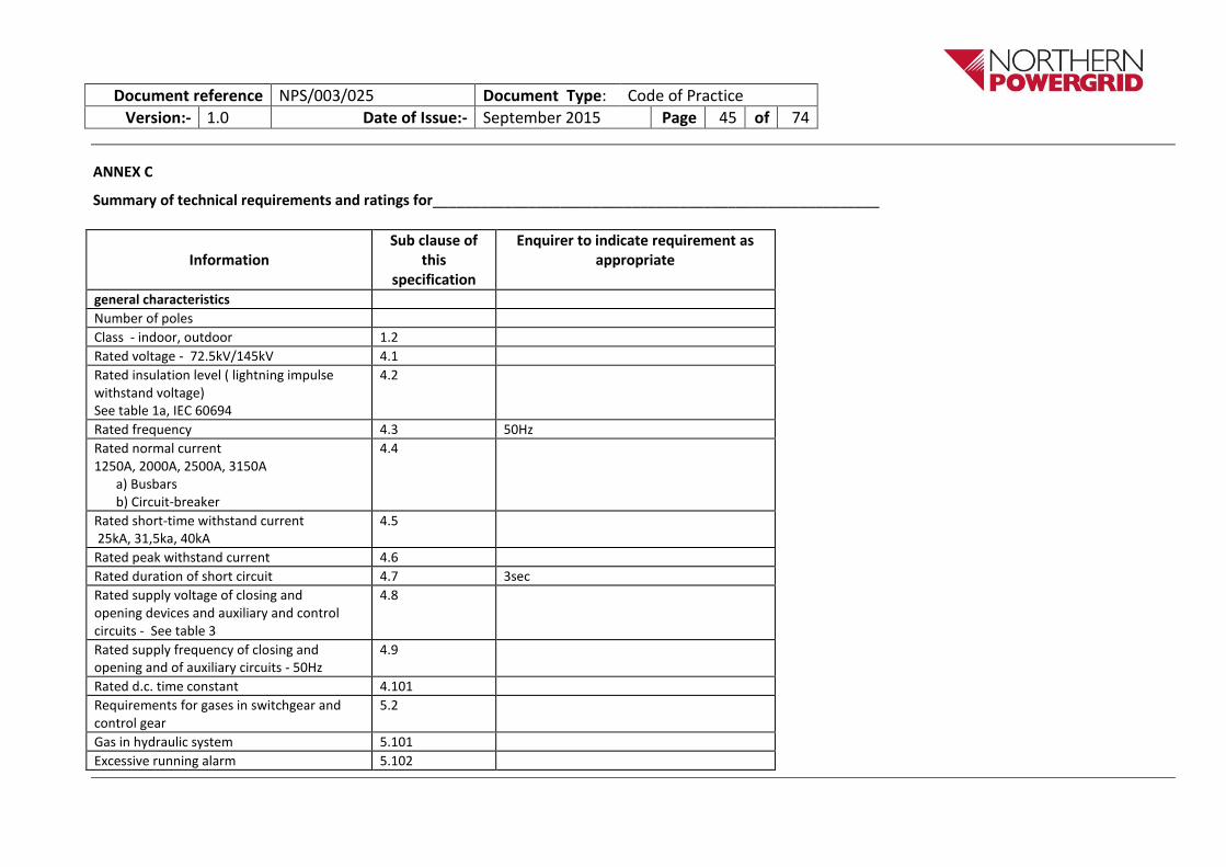
ANNEX C
Summary of technical requirements and ratings for________________________________________________________
Information
Sub clause of this
specification
Enquirer to indicate requirement as appropriate
general characteristics
Number of poles
Class - indoor, outdoor 1.2
Rated voltage - 72.5kV/145kV 4.1
Rated insulation level ( lightning impulse withstand voltage) See table 1a, IEC 60694
4.2
Rated frequency 4.3 50Hz
Rated normal current 1250A, 2000A, 2500A, 3150A
a) Busbars b) Circuit-breaker
4.4
Rated short-time withstand current 25kA, 31,5ka, 40kA
4.5
Rated peak withstand current 4.6
Rated duration of short circuit 4.7 3sec
Rated supply voltage of closing and opening devices and auxiliary and control circuits - See table 3
4.8
Rated supply frequency of closing and opening and of auxiliary circuits - 50Hz
4.9
Rated d.c. time constant 4.101
Requirements for gases in switchgear and control gear
5.2
Gas in hydraulic system 5.101
Excessive running alarm 5.102

Document reference NPS/003/025 Document Type: Code of Practice
Version:- 1.0 Date of Issue:- September 2015 Page 46 of 74
Gas filling valve 5.2.104
Lockable gas service valves 5.2.106
Gas monitoring - a) Pressure / density gauge / indicator b) Single stage pressure switch c) Two stage pressure switch d) Other monitoring device
5.9.101
Padlocking facilities , padlock 41mm square body with a 4mm to 7mm shackle inside length 16mm to 45mm
5.11.102
Protection of persons against access to hazardous parts
5.13.1
Protection against ingress of water IP 3XDW
5.13.2
Protection against mechanical impact 2J indoor, 5J outdoor.
5.13.3
Gas leakage rate not exceed 1% at 20ºC 5.15.1
Lifting points markings 5.105
Surface preparation 5.106

Document reference NPS/003/025 Document Type: Code of Practice
Version:- 1.0 Date of Issue:- September 2015 Page 47 of 74
SELF CERTIFICATION CONFORMANCE DECLARATION CLAUSE BY CLAUSE CONFORMANCE WITH ENA TS 41-37 – Part 2 ADDITIONAL CLAUSES FOR GIS SWITCHGEAR
Switchgear covered by ENA TS 41-37 shall comply with the latest issues of the relevant International and British Standards. ENA TS 41-37 is intended to amplify and/or clarify
The Requirements of those Standards. This check sheet identifies the clauses in ENA TS 41-37 - Part 2 and the clauses of the aforementioned Standards relevant to clauses for GIS for high-voltage switchgear The manufacturer shall declare conformity or otherwise, clause by clause, using the following levels of conformance declaration codes.
Conformance declaration codes N/A = Clause is not applicable/appropriate to the product Cs1 = the product is fully conforms with the requirements of this clause Cs2 = the product is partially conforms with the requirements of this clause Cs3 = the product does not conform with the requirements of this clause Cs4 = the product does not currently conform with the requirements of this clause, but the Manufacturer proposes to modify and test the product in order to comply.
Manufacturer: Ratings:
Product Reference :
Signature: Date:
IEC 62271-203, & IEC 62271-102 ENA TS 41-37
Clause / Subclause
Requirement Conformance code ENA TS 41-37 - Part 2 Clause / Subclause
Requirement
Conformance code Remarks
IEC62271-102
IEC62271-203
2 2 Normal and special service conditions
2 Normal and special service conditions
4 4 Ratings 4 Ratings
5 Design and construction
5 Design and construction
Instructions for completion
Explanatory comments must be added for ALL clauses, regardless of conformance code.
Prefix each remark with the relevant ‘I EC’ or ‘ENATS’ as appropriate

Document reference NPS/003/025 Document Type: Code of Practice
Version:- 1.0 Date of Issue:- September 2015 Page 48 of 74
IEC 62271-203, & IEC 62271-102 ENA TS 41-37
Clause / Subclause
Requirement Conformance code ENA TS 41-37 - Part 2 Clause / Subclause
Requirement
Conformance code Remarks
IEC62271-102
IEC62271-203
5.1 5.1 Requirements for liquids in switchgear and control gear
5.1 Requirements for liquids in switchgear and control gear
5.3 5.3 Earthing of switchgear and control gear
5.3 Earthing of switchgear and control gear
5.3.201 Earthing facilities general
5.3.202 Additional Earths
5.4 5.4 Auxiliary and control equipment
5.4 Auxiliary and control equipment
5.5 5.5 Dependent power operation
5.5 Dependent power operation
5.6 5.6 Stored energy operation
5.6 Stored energy operation
5.7 5.7 Independent manual operation
5.7. Independent manual operation
5.8 5.8 Operation of releases 5.8 Operation of releases
5.9 5.9 Low and high-pressure interlocking and monitoring devices
5.9 Low and high-pressure interlocking and monitoring devices
5.9.101 Remote alarm
5.9.102 Temporary blocking of alarms
5.9.103 Dual pressure systems
5.9.104 Replacement of gas sensors
5.10 5.10 Nameplates 5.10. Nameplates

Document reference NPS/003/025 Document Type: Code of Practice
Version:- 1.0 Date of Issue:- September 2015 Page 49 of 74
IEC 62271-203, & IEC 62271-102 ENA TS 41-37
Clause / Subclause
Requirement Conformance code ENA TS 41-37 - Part 2 Clause / Subclause
Requirement
Conformance code Remarks
IEC62271-102
IEC62271-203
5.11 5.11 Interlocking devices 5.11 Interlocking devices and padlocking facilities
5.11.101 Circuit-breakers/disconnector interlocking
5.11.102 Earth interlock
5.13 5.13 Degrees of protection by compartments
5.13 Degrees of protection by compartments
5.14 5.14 Creepage distances 5.14 Creepage distances and environmental considerations
5.16 5.16 Liquid tightness 5.16 Sub –clause 5.16 does not apply
5.105 5.102 Internal Fault 5.102 Internal fault
5.102.2 External effects 5.102.2 External effects of the arc
5.103 Enclosures 5.103 Enclosures
5.104 Partitions 5.104 Partitions
5.201 Test facilities General
5.201.1 Test bushings
5.202 Cable testing
5.202.1 Test bushings – DC testing
5.202.2 Cable DC testing
5.203 Injection testing of CT’s
5.204 Outage constraints
6 6 Type tests 6 Type tests
6.2.9 Partial discharge tests
7 7 Routine tests 7 Routine tests

Document reference NPS/003/025 Document Type: Code of Practice
Version:- 1.0 Date of Issue:- September 2015 Page 50 of 74
IEC 62271-203, & IEC 62271-102 ENA TS 41-37
Clause / Subclause
Requirement Conformance code ENA TS 41-37 - Part 2 Clause / Subclause
Requirement
Conformance code Remarks
IEC62271-102
IEC62271-203
8 8 Guide to the selection of switchgear and control gear
8 Guide to the selection of switchgear and control gear
9 9 Information to be given with enquiries, tenders and orders
9 Information to be given with enquiries, tenders and orders
10 10 Rules for Transport, Storage, installation, operation and maintenance
10 Rules for Transport, Storage, installation, operation, maintenance and disposal
11 11 Safety 11 Safety
12 Environmental Aspects
12 Environmental Aspects
13 Commissioning
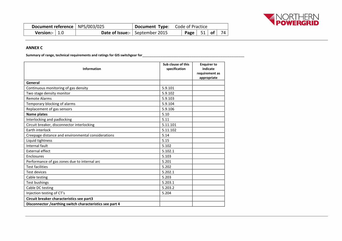
Document reference NPS/003/025 Document Type: Code of Practice
Version:- 1.0 Date of Issue:- September 2015 Page 51 of 74
ANNEX C
Summary of range, technical requirements and ratings for GIS switchgear for________________________________________________________
Information
Sub clause of this specification
Enquirer to indicate
requirement as appropriate
General
Continuous monitoring of gas density 5.9.101
Two stage density monitor 5.9.102
Remote Alarms 5.9.103
Temporary blocking of alarms 5.9.104
Replacement of gas sensors 5.9.106
Name plates 5.10
Interlocking and padlocking 5.11
Circuit breaker, disconnector interlocking 5.11.101
Earth interlock 5.11.102
Creepage distance and environmental considerations 5.14
Liquid tightness 5.15
Internal fault 5.102
External effect 5.102.1
Enclosures 5.103
Performance of gas zones due to internal arc 5.201
Test facilities 5.202
Test devices 5.202.1
Cable testing 5.203
Test bushings 5.203.1
Cable DC testing 5.203.2
Injection testing of CT’s 5.204
Circuit breaker characteristics see part3
Disconnector /earthing switch characteristics see part 4

Document reference NPS/003/025 Document Type: Code of Practice
Version:- 1.0 Date of Issue:- September 2015 Page 52 of 74
PART 2 – Gas Insulated metal enclosed Switchgear - TYPE TEST CONFORMANCE DECLARATION 2.1
Manufacturer:
Ratings:
Product reference:
Name: Signature: Date:
Instructions for completion:
Complete a separate table for each variant and rating
ENA/SAP to complete columns 1 to 4
Manufacturer to complete columns 5 to 10
Tests not requested may be shown as ‘Additional tests’ at the bottom of the table
*See bottom of table for conformance declaration codes
** I = Independent; M= Manufacturer; ENA= Energy Networks Association

Document reference NPS/003/025 Document Type: Code of Practice
Version:- 1.0 Date of Issue:- September 2015 Page 53 of 74
Test Requirement Specification and Standards Rated value Test req’d Y or N
Conformance Test value
Date of test
Test station Report / Cert
No
Witness I, M or ENA **
Remarks
1 Dielectric Circuit breaker-disconnector and earthing switches as appropriate.
IEC 60694.sublause6.2, IEC 62271-203. Clause 6.2, IEC 62271-100. Subclause 6.2.
Partial discharge
Subclause 7.101 IEC62271-103 ENA TS 41-18
DC Withstand Test on Test Devices, including all parts of main circuit, which cannot be disconnected from the test connections.
Subclause 5.107.1 IEC 62271-203 Subclause 5.202 of ENA TS 41-37 Part 2
2 Radio interference test Subclause 6.3 IEC 62271-203
3 Measurement of the resistance of main circuit -
Subclause 6.4 IEC 62271-203
4 Temperature Rise Subclause 6.5, IEC 62271-203.
5 Short-time withstand current and peak withstand current tests -
Subclause 6.6, IEC 62271-203.
6 Demonstration of arcing times Subclause 6.102.10, IEC 62271-100
7 Three phase tests Subclause 6.102.10.1, IEC 62271-100
8 Test duties T10,T30,T60,T100s(b).OP1 and OP2
Subclause 6.102.10.1.1, IEC 62271-100
9 Test duty T100a Subclause 6.102.1.2, IEC 62271-100
10 Tests on earthing circuits Subclause 6.6.102 IEC 62271-203.
11 Verification of protection Subclause 6.7, IEC 62271-203.
12 EMC tests IEC 60694.subclause 6.9
13 Gas tightness test IEC 60694 subclause 6.8 &IEC 62271-203 subclause 6.8
14 Electromagnetic compatibility IEC 60694 subclause 6.9 & IEC 600271-203 subclause 6.9
15 Mechanical and environmental tests – circuit breaker.
IEC 62271-203 Subclause 6.102, IEC 62271-100. Subclause 6.101
16 Mechanical and environmental tests – disconnector and earthing switches.
IEC 62271-203 subclause 6.102, IEC 62271-102. subclause 6.102
17 Proof tests for enclosures IEC 62271-203. subclause 6.103
18 Pressure test on partitions IEC 62271-203. subclause 6.104

Document reference NPS/003/025 Document Type: Code of Practice
Version:- 1.0 Date of Issue:- September 2015 Page 54 of 74
Test Requirement Specification and Standards Rated value Test req’d Y or N
Conformance Test value
Date of test
Test station Report / Cert
No
Witness I, M or ENA **
Remarks
19 Internal fault IEC 62271-203. subclause 6.105
20 Insulator tests IEC 62271-203. subclause 6.106
21 Additional tests on auxiliary and control circuits
Subclauses of IEC 60694 incorporating Amd 2
- Dielectric IEC 60694 incorporating Amd 2 Sub-clause 6.2.10
- Measurement of resistance IEC 60694 incorporating Amd 2 Sub-clause 6.4.2
- Temperature rise IEC 60694 Sub-clause 6.5.5 - Functional IEC 60694 incorporating Amd 2 Sub-
clause 6.10.2
- Electrical continuity or earthed metallic parts
IEC 60694 incorporating Amd 2 Sub-clause 6.10.3
- Verification of operational characteristics (Auxiliary contacts)
IEC 60694 incorporating Amd 2 Sub-clause 6.10.4
- Ripple on d.c. input power port immunity
IEC 60694 incorporating Amd 2 Sub-clause 6.10.5
- Environmental (Cold; Dry heat; Damp heat, steady state; Cyclic humidity; Vibration response & seismic; Final condition check)
IEC 60694 incorporating Amd 2 Sub-clause 6.10.7
22 Finish Performance to ENATS 98-1
23 Process Control ISO 9001 ERG79 Parts 1 & 2a 36 monthly surveillance checks to maintain validity of the Notice
* Conformance declaration codes
N/A = Clause is not applicable/appropriate to the product Cs1 = the test conforms fully with the requirements of this clause Cs2 = the test conforms partially with the requirements of this clause Cs3 = the test does not conform to the requirements of this clause Cs4 = Test not performed, but alternative evidence/ technical case offered
Ct1 = Independent witnessed tests Ct2 = Not fully independent witnessed tests Ct3 = Self verified tests Ct4 = Alternative tests / evidence offered Ct5 = Manufacturer has underwritten that the product meets the functional and
performance requirements without further testing. Ct6 = Not tested
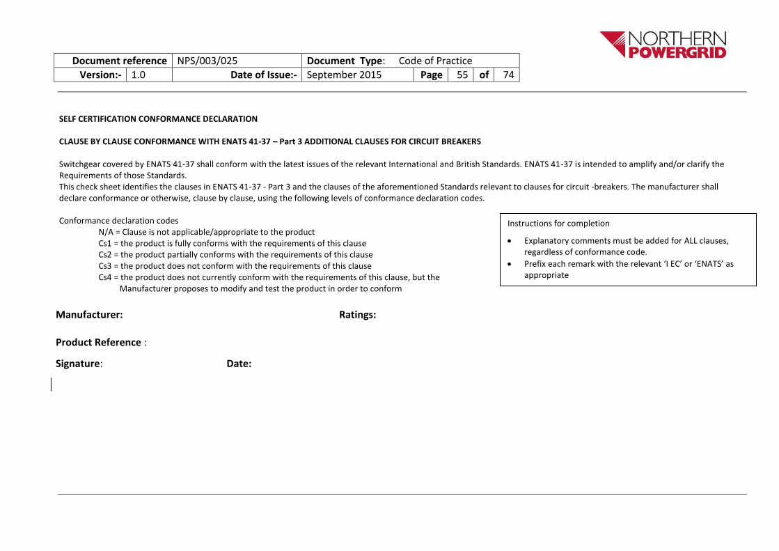
Document reference NPS/003/025 Document Type: Code of Practice
Version:- 1.0 Date of Issue:- September 2015 Page 55 of 74
SELF CERTIFICATION CONFORMANCE DECLARATION
CLAUSE BY CLAUSE CONFORMANCE WITH ENATS 41-37 – Part 3 ADDITIONAL CLAUSES FOR CIRCUIT BREAKERS
Switchgear covered by ENATS 41-37 shall conform with the latest issues of the relevant International and British Standards. ENATS 41-37 is intended to amplify and/or clarify the Requirements of those Standards. This check sheet identifies the clauses in ENATS 41-37 - Part 3 and the clauses of the aforementioned Standards relevant to clauses for circuit -breakers. The manufacturer shall declare conformance or otherwise, clause by clause, using the following levels of conformance declaration codes. Conformance declaration codes
N/A = Clause is not applicable/appropriate to the product Cs1 = the product is fully conforms with the requirements of this clause Cs2 = the product partially conforms with the requirements of this clause Cs3 = the product does not conform with the requirements of this clause Cs4 = the product does not currently conform with the requirements of this clause, but the Manufacturer proposes to modify and test the product in order to conform
Manufacturer: Ratings:
Product Reference :
Signature: Date:
Instructions for completion
Explanatory comments must be added for ALL clauses, regardless of conformance code.
Prefix each remark with the relevant ‘I EC’ or ‘ENATS’ as appropriate

Document reference NPS/003/025 Document Type: Code of Practice
Version:- 1.0 Date of Issue:- September 2015 Page 56 of 74
IEC 60694,& IEC 62271-100 ENATS 41-37
Clause / subclause
Requirement Conformance code
ENATS 41-37 Part 3 Clause / sub clause
Requirement
Conformance code Remarks
IEC62271-100 IEC60694
2 2 Normal and special service conditions
2 Normal and special service conditions
4 4 Ratings 4 Ratings
4.101 Rated short-circuit breaking current
4.102 TRV related to rated short-circuit breaking current
4.103 Rated short circuit making current
4.104 Operating sequence
4.105 Characteristics for short line faults
4.106 Rated out –of- phase making and breaking current
4.107 Rated capacitive switching currents
4.108 Small inductive breaking current
4.109 Rated DC time constant
4.110 4.110 Number of mechanical operations
4.110 Number of mechanical operations
5 5 Design and construction
5 Design and construction
5.2 5.2 Requirements for gases 5.2 Requirements for gases in circuit-breakers
5.3 5.3 Earthing of switchgear and control gear
5.3 Earthing of circuit-breakers

Document reference NPS/003/025 Document Type: Code of Practice
Version:- 1.0 Date of Issue:- September 2015 Page 57 of 74
IEC 60694,& IEC 62271-100 ENATS 41-37
Clause / subclause
Requirement Conformance code
ENATS 41-37 Part 3 Clause / sub clause
Requirement
Conformance code Remarks
IEC62271-100 IEC60694
5.4 5.4 Auxiliary and control equipment
5.4 Auxiliary and control equipment
5.4.101 Trip circuit supervision
5.4.102 Trip coil isolation
5.4 103 Forced opening
5.5 5.5 Dependent power operation
5.5 Dependent power operation
5.5.101 Anti pumping
5.5.102 Operating systems interlocks
5.5.103 Circuit breakers with independent drive mechanisms
5.5.104 Simultaneous pole operation
5.6 5.6 Stored energy operation
5.6 Stored energy closing
5.6.101 Three pole operation
5.6.102 Tripping Mechanism
5.7 Independent manual operation,
5.8 5.8 Operation of releases 5.8 Operation of releases
5.8.201 Local manual operation
5.8.202 Slow closing and opening
5.8.203 Operations counter
5.9 5.9 Low and high-pressure interlocking and monitoring devices
5.9 Low and high-pressure interlocking and monitoring devices
5.10 Nameplates
5.10.101 Trip and close isolation shall be labelled

Document reference NPS/003/025 Document Type: Code of Practice
Version:- 1.0 Date of Issue:- September 2015 Page 58 of 74
IEC 60694,& IEC 62271-100 ENATS 41-37
Clause / subclause
Requirement Conformance code
ENATS 41-37 Part 3 Clause / sub clause
Requirement
Conformance code Remarks
IEC62271-100 IEC60694
5.11 5.11 Interlocking devices 5.11 Interlocking devices and padlocking facilities
5.11.101 Mechanical key interlocking
5.12 5.12 Position indications 5.12 Position indications
5.201 Structure mounted open terminal circuit-breakers
5.202 Circuit identification
5.203 Noise
5.204 CT labels
6 6 Type tests 6 Type tests
6.104.2 Short circuit making current
6.104.2 Short-circuit making current
6.104.5.4 Test duty T30 6.104.5.4 Test duty T30
6.110 Out-of-phase condition 6.110 Out-of-phase condition
6.111 Capacitive current switching
6.201 Sound pressure measurement
6.202 Breaking test with asymmetrical current
7 7 Routine tests 7 Routine tests
8 8 Guide to the selection of switchgear and control gear
8 Guide to the selection of circuit –breakers for service.
9 9 Information to be given with enquiries, tenders and orders
9 Information to be given with enquiries, tenders and orders

Document reference NPS/003/025 Document Type: Code of Practice
Version:- 1.0 Date of Issue:- September 2015 Page 59 of 74
IEC 60694,& IEC 62271-100 ENATS 41-37
Clause / subclause
Requirement Conformance code
ENATS 41-37 Part 3 Clause / sub clause
Requirement
Conformance code Remarks
IEC62271-100 IEC60694
10 10 Rules for Transport, Storage, installation, operation and maintenance
10 Rules for transport, storage, installation, operation, maintenance and disposal
11 11 Safety 11 Safety
12 Environmental Aspects 12 Environmental aspects
13 Commissioning tests

Document reference NPS/003/025 Document Type: Code of Practice
Version:- 1.0 Date of Issue:- September 2015 Page 60 of 74
PART 3 – High Voltage Circuit-breakers - TYPE TEST CONFORMANCE DECLARATION 3.1
Manufacturer:
Ratings:
Product reference:
Name: Signature: Date:
1. 2. 3. 4. 5. 6. 7. 8. 9. 10.
Test Requirement Specification and Standards
Rated value
Test req’d Y
or N
Conformance Test value
Date of test
Test station
Report / Cert No
Witness I, M or
ENA**
Remarks
1 Dielectric
Subclause 6.2. IEC 62271-100.
2 Radio interference test Subclause 6.3 IEC 62271-100
3 Measurement of the resistance of main circuit -
Subclause 6.4 IEC 62271-100
4 Temperature Rise Subclause 6.5, IEC 62271-100
Instructions for completion
Explanatory comments must be added for ALL clauses, regardless of conformance code.
Prefix each remark with the relevant ‘I EC’ or ‘ENATS’ as appropriate
Type test reports table based on ENATS 41-37 Table 3.1
*See bottom of table for conformance declaration codes
** I = Independent; M= Manufacturer; ENA= Energy Networks Association

Document reference NPS/003/025 Document Type: Code of Practice
Version:- 1.0 Date of Issue:- September 2015 Page 61 of 74
1. 2. 3. 4. 5. 6. 7. 8. 9. 10.
Test Requirement Specification and Standards
Rated value
Test req’d Y
or N
Conformance Test value
Date of test
Test station
Report / Cert No
Witness I, M or
ENA**
Remarks
5 Short-time withstand current and peak withstand current tests -
Subclause 6.6, IEC 62271-100
6 Demonstration of arcing times
Subclause 6.102.10, IEC 62271-100
7 Three phase tests Subclause 6.102.10.1, IEC 62271-100
8 Test duties T10,T30,T60,T100s(b).OP1 and OP2
Subclause 6.102.10.1.1, IEC 62271-100
9 Test duty T100a Subclause 6.102.1.2, IEC 62271-100
10 Tightness test Subclause 6.8 IEC 62271-100
11 EMC tests Subclause 6.9 IEC 62271-100
12 Mechanical operation test at ambient temperature
Subclause 6.6.101.2.1 to 6.101.2.3 IEC 62271-100
13 Short-circuit current making and breaking tests
Subclause 6.102 to 6.106 IEC 62271-100
14 Capacitive current switching tests
Subclause 6.111.5.1 IEC 62271-100
15 Verification of protection Subclause 6.7, IEC 62271-100
16 Low/high Temperature tests Subclause 6.101.3 IEC 62271-100

Document reference NPS/003/025 Document Type: Code of Practice
Version:- 1.0 Date of Issue:- September 2015 Page 62 of 74
1. 2. 3. 4. 5. 6. 7. 8. 9. 10.
Test Requirement Specification and Standards
Rated value
Test req’d Y
or N
Conformance Test value
Date of test
Test station
Report / Cert No
Witness I, M or
ENA**
Remarks
17 Humidity test Subclause 6.101.4 IEC 62271-100.
18 Static terminal load test Subclause 6.101.6 IEC 62271-100
19 Critical current test Subclause 6.107 IEC 62271-100
20 Out-of-phase making and breaking test*
Subclause 6.110 IEC 62271-100.
21 Tests to prove operation under severe ice conditions*
Subclause 6.101.5 IEC 62271-100
22 Single-phase and double earth fault tests*
Subclause 6.108 IEC 62271-100
23 Cable-charging current breaking test*
Subclause 6.111,5.2 IEC 62271-100
24 Single capacitor bank switching tests*
Subclause 6.111.5.3 IEC 62271-100
25 Back-to-back capacitor switching tests*
Subclause 6.111.5.3 IEC 6271-100
26 Additional tests on auxiliary and control circuits
Subclauses of IEC 60694 incorporating Amd 2
- Dielectric IEC 60694 incorporating Amd 2 Sub-clause 6.2.10
- Measurement of resistance IEC 60694 incorporating Amd 2 Sub-clause 6.4.2
- Temperature rise IEC 60694 Sub-clause 6.5.5 - Functional IEC 60694 incorporating
Amd 2 Sub-clause 6.10.2

Document reference NPS/003/025 Document Type: Code of Practice
Version:- 1.0 Date of Issue:- September 2015 Page 63 of 74
1. 2. 3. 4. 5. 6. 7. 8. 9. 10.
Test Requirement Specification and Standards
Rated value
Test req’d Y
or N
Conformance Test value
Date of test
Test station
Report / Cert No
Witness I, M or
ENA**
Remarks
- Electrical continuity or earthed metallic parts
IEC 60694 incorporating Amd 2 Sub-clause 6.10.3
- Verification of operational characteristics (Auxiliary contacts)
IEC 60694 incorporating Amd 2 Sub-clause 6.10.4
- Ripple on d.c. input power port immunity
IEC 60694 incorporating Amd 2 Sub-clause 6.10.5
- Environmental (Cold; Dry heat; Damp heat, steady state; Cyclic humidity; Vibration response & seismic; Final condition check)
IEC 60694 incorporating Amd 2 Sub-clause 6.10.7
27 Finish Performance to ENATS 98-1
28 Process Control ISO 9001 ERG79 Parts 1 & 2a
36 monthly surveillance checks to maintain validity of the Notice
Note: All type tests carried out using the number of test samples specified 6.1.1 of IEC 60694 and in 6.102.2 of IEC62271-100 for circuit breakers with a rated voltage of 72.5kV and above tests marked by * an additional test sample is allowed for the marked test.
* Conformance declaration codes
N/A = Clause is not applicable/appropriate to the product Cs1 = the test conforms fully with the requirements of this clause Cs2 = the test conforms partially with the requirements of this clause Cs3 = the test does not conform to the requirements of this clause Cs4 = Test not performed, but alternative evidence/ technical case offered
Ct1 = Independent witnessed tests
Ct2 = Not fully independent witnessed tests
Ct3 = Self verified tests
Ct4 = Alternative tests / evidence offered
Ct5 = Manufacturer has underwritten that the product meets the functional and performance requirements without further testing.
Ct6 = Not tested

Document reference NPS/003/025 Document Type: Code of Practice
Version:- 1.0 Date of Issue:- September 2015 Page 64 of 74
ANNEX C
Summary of range, technical requirements and ratings for circuit-breaker requirements for________________________________________________________ Information
Subclause of this specification
Enquirer to indicate requirement as appropriate
Rated short-circuit breaking current Equal to rated short-time withstand current 25kA, 31.5kA 40kA
4.101
Rated short-circuit making current 4.103 2.7 times rated short-circuit breaking current
Rated operating sequence 4.104
Characteristics for short line faults 4.105
Out-of-phase making and breaking 4.106
Rated capacitive switching currents ( Class C2)
4.107
Rated small inductive breaking current 4.108
Rated time quantities 4.109
Classification of mechanical operations Class M1-2000ops, Class M2-10000ops
4.110
Electrical endurance 4.111
Forced opening 5.4.103
Excessive running time alarm 5.1.104
Minimum withstand level 5.1.105
Forced opening 5.4.103
Anti pumping 5.5.101
Circuit breakers with independent drive mechanisms
5.5.103
Three pole operation 5.6.101
Local manual tripping 5.8.201

Document reference NPS/003/025 Document Type: Code of Practice
Version:- 1.0 Date of Issue:- September 2015 Page 65 of 74
Local manual closing 5.8.202
Noise Not greater than 90db 5.204
Breaking test with asymmetrical current 6.203

Document reference NPS/003/025 Document Type: Code of Practice
Version:- 1.0 Date of Issue:- September 2015 Page 66 of 74
SELF CERTIFICATION CONFORMANCE DECLARATION CLAUSE BY CLAUSE CONFORMANCE WITH ENA TS 41-37 – Part 4 ADDITIONAL CLAUSES FOR High Voltage Disconnectors and Earthing switches Switchgear covered by ENA TS 41-37 shall comply with the latest issues of the relevant International and British Standards. ENA TS 41-37 is intended to amplify and/or clarify the requirements of those Standards. This check sheet identifies the clauses in ENA TS 41-37 - Part 2 and the clauses of the aforementioned Standards relevant to clauses High voltage Disconnectors and Earthing switches The manufacturer shall declare conformance or otherwise, clause by clause, using the following levels of conformance declaration codes.
Conformance declaration codes
N/A = Clause is not applicable or appropriate to the product Cs1 = the product is fully conforms with the requirements of this clause Cs2 = the product partially conforms with the requirements of this clause Cs3 = the product does not conform with the requirements of this clause Cs4 = the product does not currently conform with the requirements of this clause, but the Manufacturer proposes to modify and test the product in order to comply.
Manufacturer: Ratings:
Product Reference:
Signature: Date:
Instructions for completion
Explanatory comments must be added for ALL clauses, regardless of conformance code.
Prefix each remark with the relevant ‘I EC’ or ‘ENATS’ as appropriate

Document reference NPS/003/025 Document Type: Code of Practice
Version:- 1.0 Date of Issue:- September 2015 Page 67 of 74
IEC 62271-203, & IEC 62271-102 ENA TS 41-37
Clause / Subclause
Requirement Conformance code
ENA TS 41-37 - Part 4 Clause / Subclause
Requirement
Conformance code
Remarks
Part I of 41-37
IEC62271 -102
2 2 Normal and special service conditions
2 Normal and special service conditions
3 3 Definitions 3 Definitions
4 4 Ratings 4 Ratings
4.104. 4.104 Bus transfer
4.105 4.105 Induced current switching Line earthing switches
4.106 4.106 Mechanical endurance
4.201 Earthing Devices having a rating short circuit making current
1.5 5 Design and construction
5 Design and construction
5.4 5.4 Auxiliary and control equipment
5.4 Auxiliary and control equipment
5.4.101 Setting adjustment of Auxiliary switches
5.11 5.11 Interlocking devices
5.11 Interlocking and padlocking facilities
5.11.101 Disconnector and earthing switch interlocking
5.11.102 Key operated interlocking 5.11.102.1 Interlock key release position

Document reference NPS/003/025 Document Type: Code of Practice
Version:- 1.0 Date of Issue:- September 2015 Page 68 of 74
IEC 62271-203, & IEC 62271-102 ENA TS 41-37
Clause / Subclause
Requirement Conformance code
ENA TS 41-37 - Part 4 Clause / Subclause
Requirement
Conformance code
Remarks
Part I of 41-37
IEC62271 -102
5.201 Disconnector three- pole operation
5.202 Operations counter 5.203 Manually operation of
disconnectors with bus-transfer duty
5.204 Installation tolerances 6 6 Type tests 6 Type tests 6.102.3 6.102.3 Mechanical endurance tests 7 7 Routine tests 7 Routine tests 8 8 Guide to selection
of disconnectors and earthing switches
8 Guide to selection of disconnectors and earthing switches
9 9 Information to be given with enquires, tenders and orders
9 Information to be given with enquires, tenders and orders
10 10 Rules for transport, storage, installation, operation and maintenance
10 Rules for transport, storage, installation, operation, maintenance and disposal
10.101 Assembly instructions

Document reference NPS/003/025 Document Type: Code of Practice
Version:- 1.0 Date of Issue:- September 2015 Page 69 of 74
IEC 62271-203, & IEC 62271-102 ENA TS 41-37
Clause / Subclause
Requirement Conformance code
ENA TS 41-37 - Part 4 Clause / Subclause
Requirement
Conformance code
Remarks
Part I of 41-37
IEC62271 -102
11 11 Safety 11 Safety 12 Environmental
Aspects 12 Environmental aspects

Document reference NPS/003/025 Document Type: Code of Practice
Version:- 1.0 Date of Issue:- September 2015 Page 70 of 74
ANNEX B – ENA TS 41-37
SELF CERTIFICATION CONFORMANCE DECLARATION PART 4 – High Voltage Disconnectors and Earthing Switches - TYPE TEST CONFORMANCE DECLARATION 4.1
Manufacturer:
Ratings:
Product reference:
Name: Signature: Date:
Instructions for completion
Explanatory comments must be added for ALL clauses, regardless of conformance code.
Prefix each remark with the relevant ‘I EC’ or ‘ENATS’ as appropriate
*See bottom of table for conformance declaration codes
** I = Independent; M= Manufacturer; ENA= Energy Networks Association

Document reference NPS/003/025 Document Type: Code of Practice
Version:- 1.0 Date of Issue:- September 2015 Page 71 of 74
1. 2. 3. 4. 5. 6. 7. 8. 9. 10.
Test Requirement Specification and Standards Rated value
Test req’d Y
or N
Conformance Test value
Date of test
Test station Report / Cert
No
Witness I, M or
ENA**
Remarks
1 Dielectric
Subclause 6.2. IEC 62271-102.
Partial discharge
Subclause 7.101 IEC62271-103 ENA TS 41-18
2 Radio interference test Subclause 6.3 IEC 60694
3 Measurement of the resistance of main circuit -
Subclause 6.4 IEC 60694
4 Temperature Rise Subclause 6.5, IEC 60694
5 Short-time withstand current and peak withstand current tests -
Subclause 6.6 IEC 62271-102 and IEC 60694 Subclause6.6.1
6 Verification of protection Subclause 6.7 IEC 60694
7 Tightness test Subclause 6.8 IEC 60694
8 EMC tests Subclause 6.9 IEC 60694
9 Tests to prove the short circuit making performance of earthing switches.
Subclause 6.101 IEC 62271-102
10 Operating and mechanical endurance test
Subclause 6.102 IEC 62271-102
11 Operation under severe ice conditions
Subclause 6.103 IEC 62271-102
12 Operation at the temperature limits
Subclause 6.104 IEC 62271-102
13 Tests to prove the proper function of the position –indicating device
Subclause 6.105 IEC 62271-102
14 Bus-transfer current switching test
Subclause 6.106 IEC 62271-102
15 Induced current switching tests
Subclause 6.107 IEC 62271-102.

Document reference NPS/003/025 Document Type: Code of Practice
Version:- 1.0 Date of Issue:- September 2015 Page 72 of 74
1. 2. 3. 4. 5. 6. 7. 8. 9. 10.
Test Requirement Specification and Standards Rated value
Test req’d Y
or N
Conformance Test value
Date of test
Test station Report / Cert
No
Witness I, M or
ENA**
Remarks
16 Bus-charging switching tests Subclause 6.108 IEC 62271-102
17 Additional tests on auxiliary and control circuits
Subclauses of IEC 60694 incorporating Amd 2
- Dielectric IEC 60694 incorporating Amd 2 Sub-clause 6.2.10
- Measurement of resistance IEC 60694 incorporating Amd 2 Sub-clause 6.4.2
- Temperature rise IEC 60694 Sub-clause 6.5.5 - Functional IEC 60694 incorporating Amd
2 Sub-clause 6.10.2
- Electrical continuity or earthed metallic parts
IEC 60694 incorporating Amd 2 Sub-clause 6.10.3
- Verification of operational characteristics (Auxiliary contacts)
IEC 60694 incorporating Amd 2 Sub-clause 6.10.4
- Ripple on d.c. input power port immunity
IEC 60694 incorporating Amd 2 Sub-clause 6.10.5
- Environmental (Cold; Dry heat; Damp heat, steady state; Cyclic humidity; Vibration response & seismic; Final condition check)
IEC 60694 incorporating Amd 2 Sub-clause 6.10.7
18 Finish Performance to ENA TS 98-1
19 Process Control ISO 9001 ERG79 Parts 1 & 2a 24 monthly surveillance checks to maintain validity of the Notice
Note: All type tests carried out using the number of test samples specified in 6.1.1 of IEC 60694. Disconnectors and earthing switches with a rated voltage of 72.5kV and above tests marked by * an additional test sample is allowed for the marked test.

Document reference NPS/003/025 Document Type: Code of Practice
Version:- 1.0 Date of Issue:- September 2015 Page 73 of 74
* Conformance declaration codes N/A = Clause is not applicable/appropriate to the product Cs1 = the test conforms fully with the requirements of this clause Cs2 = the test conforms partially with the requirements of this clause Cs3 = the test does not conform to the requirements of this clause Cs4 = Test not performed, but alternative evidence/ technical case offered
Ct1 = Independent witnessed tests
Ct2 = Not fully independent witnessed tests
Ct3 = Self-verified tests
Ct4 = Alternative tests / evidence offered
Ct5 = Manufacturer has underwritten that the product meets the functional and performance requirements without further testing.
Ct6 = Not tested

Document reference NPS/003/025 Document Type: Code of Practice
Version:- 1.0 Date of Issue:- September 2015 Page 74 of 74
ANNEX C
Summary of range, technical requirements and ratings for disconnector and earthing switch requirements for________________________________________________________
Information
Clause of this specification
Enquirer to indicate requirement as appropriate
Rated short circuit making current 4
Rated mechanical terminal load IEC 62271-102 subclause 4.103
4.103
Rated bus-transfer current switching IEC 62271-102 subclause 4.104
4.104
Rated induced current switching of Earthing switches IEC 62271-102 4.105
4.105
Classification of mechanical operations Class M0-1000 , M1-2000 ops or M2-10000 ops
4.106
Rated values of electrical endurance IEC 62271-102 subclause 4.107
4.107
4.5.4.101 Auxiliary switches 5.4.101
Earthing of disconnectors and earthing switches Subclause E5.3 of IEC 62271-102
E5.3