Embed Size (px)
Citation preview

INTERNATIONAL JOURNAL FOR NUMERICAL METHODS IN ENGINEERINGInt. J. Numer. Meth. Engng (2011)Published online in Wiley Online Library (wileyonlinelibrary.com). DOI: 10.1002/nme.3317
Computation of limit and shakedown loads using a node-basedsmoothed finite element method
H. Nguyen-Xuan 1,2,*,†, T. Rabczuk 3, T. Nguyen-Thoi 1,2, T. N. Tran 4 andN. Nguyen-Thanh 3
1Department of Mechanics, Faculty of Mathematics & Computer Science, University of Science HCM,227 Nguyen Van Cu, Dist. 5, Ho Chi Minh City, Vietnam
2Division of Computational Mechanics, Ton Duc Thang University, 98 Ngo Tat To St., War 19, Binh Thanh Dist.,Ho Chi Minh City, Vietnam
3Institute of Structural Mechanics (ISM), Bauhaus-University Weimar, Germany4Labor für Biomechanik, Fachhochschule Aachen, Campus Jülich Ginsterweg 1, D-52428 Jülich, Germany
SUMMARY
This paper presents a novel numerical procedure for computing limit and shakedown loads of structuresusing a node-based smoothed FEM in combination with a primal–dual algorithm. An associated primal–dual form based on the von Mises yield criterion is adopted. The primal-dual algorithm together with aNewton-like iteration are then used to solve this associated primal–dual form to determine simultaneouslyboth approximate upper and quasi-lower bounds of the plastic collapse limit and the shakedown limit. Thepresent formulation uses only linear approximations and its implementation into finite element programs isquite simple. Several numerical examples are given to show the reliability, accuracy, and generality of thepresent formulation compared with other available methods. Copyright © 2011 John Wiley & Sons, Ltd.
Received 10 March 2011; Revised 23 May 2011; Accepted 26 August 2011
KEY WORDS: finite element method; limit analysis; node-based smoothed finite element method(NS-FEM); primal–dual algorithm; shakedown analysis; strain smoothing
1. INTRODUCTION
In practical applications using the fully compatible FEM, the three-node linear triangular element(T3) and four-node linear tetrahedral element (T4) are preferred by many engineers because of theirsimplicity, robustness, less demand on the smoothness of the solution, and efficiency of adaptivemesh refinements for solutions of desired accuracy. However, the fully compatible FEM modelsusing T3 and T4 elements still possess certain inherent drawbacks: (i) they overestimate exces-sively the system stiffness matrix, which leads to poor accuracy in both displacement and stresssolutions, and (ii) they are subjected to locking in the problems with bending domination andincompressible materials.
In the effort to develop finite element technology, Liu et al. have combined the strain smoothingtechnique [1] used in meshfree methods into the FEM to formulate a cell/element-based smoothedFEM (SFEM or CS-FEM) [2–7]. Applying this strain smoothing technique on smoothing domainswill help to soften the over-stiffness of the lower-order FEM model, and hence can improve signif-icantly the accuracy of solutions in both displacement and stress. In the CS-FEM, the smoothingdomains are based on the quadrilateral elements, and each element can be further subdivided into
*Correspondence to: Nguyen-Xuan Hung, Department of Mechanics, Faculty of Mathematics & Computer Science,University of Science HCM, 227 Nguyen Van Cu, Dist. 5, Ho Chi Minh City, Vietnam.
†E-mail: [email protected]
Copyright © 2011 John Wiley & Sons, Ltd.

H. NGUYEN-XUAN ET AL.
one or some quadrilateral smoothing domains, as shown in Figure 1. The CS-FEM has been studiedtheoretically in [3–5], and further extended to the general n-sided polygonal elements (nSFEM ornCS-FEM) [6], dynamic analyses [7], incompressible materials using selective integration [8, 9],plate and shell analyses [10–12], fracture mechanics problems [13, 14], and limit analysis [15].
In the attempts to improve the performance of T3 and T4 elements, Liu et al. then extended thecell/element-based idea of smoothing domains in the CS-FEM to node-based, edge-based, face-based, and partly node-based ones with different applications to give, respectively, a node-basedsmoothed FEM (NS-FEM) [16–22, 30], an edge-based smoothed FEM (ES-FEM) [23–27, 30], anda face-based smoothed FEM (FS-FEM) [28–30]. Similar to the standard FEM, these smoothed FEM(S-FEM) models also use a mesh of elements. However, the S-FEM models evaluate the weak formbased on smoothing domains created from the entities of the element mesh such as nodes(Figure 2),edges (Figure 3), or faces (Figure 4). These smoothing domains hence cover parts of adjacent ele-ments. They are linearly independent and ensure stability and convergence of the S-FEM models.Because of the use of different smoothing domains, the softening effect of strain smoothing tech-nique on the over-stiffness of the standard FEM model will be different. Therefore, each of theS-FEM models has different properties, advantages, and disadvantages [30].
: field nodes
x1 5
8y
(c)
1x
74
9
(a)
y
4
: added nodes to form the smoothing domains
2 1 2
6
3
2
4
(d)
1
3
4
(b)
2
3
5
36
Figure 1. Division of quadrilateral element into the smoothing domains (SDs) in the CS-FEM-Q4 by con-necting the mid-segment points of opposite segments of smoothing domains: (a) 1 SD; (b) 2 SDs; (c) 4 SDs;
and (d) 8 SDs.
: field node : centroid of triangle : mid-edge point
k
(k)
(k)
Figure 2. Triangular elements and the smoothing domains�.k/ (shaded areas) associated with nodes in theNS-FEM-T3.
Copyright © 2011 John Wiley & Sons, Ltd. Int. J. Numer. Meth. Engng (2011)DOI: 10.1002/nme

NS-FEM FOR LIMIT AND SHAKEDOWN ANALYSIS OF STRUCTURES
smoothing domainsassociated with
inner edge
smoothing domain associated with boundary edge
: centroid of triangles : field node
Figure 3. Triangular elements and the smoothing domains (shaded areas) associated with edges in theES-FEM-T3.
: central point of elements (H, I)
interface k (BCD)
: field node
T4 element 1 (ABCD)
A
B
D
HI
C
T4 element 2 (BCDE)
(BCDIH)associated with interface k
smoothed domain
E
Figure 4. Tetrahedral elements and the smoothing domains (shaded areas) associated with face k in theFS-FEM-T4.
It was proved that the S-FEM models are variationally consistent based on the modified two-field Hellinger–Reissner principle. However, only unknowns of the field displacement (master field)appear in the discretized algebraic system of equations. Therefore, it is, in general, very much dif-ferent from the so-called mixed FEM formulation [31, 32], where stresses (or strains) may also beunknowns (or also master fields). More details for a general and rigorous theoretical frameworkrelated to properties, accuracy, and convergence rates of the S-FEM models have been recentlystudied in [33].
Among these S-FEM models, the NS-FEM [16–21] shows some interesting properties that arevery effective for solving nonlinear problems in solid mechanics: (i) volumetric locking is signifi-cantly alleviated; (ii) it possesses super-accurate and super-convergent properties of stress solutions;and (iii) the stress at nodes can be computed directly from the displacement solution without usingany post-process. The third property is similar to using just one Gauss point to compute the stressat nodes. The NS-FEM is hence a very convenient method for conducting the nonlinear computa-tional algorithm using the stress at nodes and is more computationally efficient and simpler thanthe standard FEM using the stresses at Gauss points located inside the element. On the basis ofthese crucial properties, the NS-FEM was then extended to analyze the visco-elastoplasticity prob-lems in two-dimensional (2D) and three-dimensional (3D) solids [19], fracture mechanics [20],
Copyright © 2011 John Wiley & Sons, Ltd. Int. J. Numer. Meth. Engng (2011)DOI: 10.1002/nme

H. NGUYEN-XUAN ET AL.
and plates [21, 22]. In this paper, the NS-FEM is further formulated for the limit and shake-down analysis of solid mechanics problems made of elastic–perfectly plastic material. Recall thatthe extension of S-FEM approaches to limit and the shakedown analysis of 2D structures hasalready been investigated in previous contributions [14, 22]. In [14], a formula to compute theplastic collapse limit factor was relied on the CS-FEM in which the smoothing domains were cre-ated based on elements, and each element was then subdivided into one or several quadrilateralsmoothing domains. In [22], we used the ES-FEM in which the smoothing domains were cre-ated based on the edges of the elements to obtain the plastic collapse limit factor. Therefore, thepresent approach in which the smoothing domains are obtained based on the nodes of the elementsis basically different from the CS-FEM and ES-FEM models. The NS-FEM is particularly moregeneral than the CS-FEM and ES-FEM because the NS-FEM can solve for both 2D and 3D prob-lems of the limit and shakedown analyses, while the CS-FEM and ES-FEM are only available for2D problems.
Limit and shakedown analysis has been a well-known tool for assessing the safety load factorof engineering structures. These load factors can be derived from upper bound and lower boundapproaches. The upper bound shakedown analysis is based on Koiter’s kinematic theorem [34](a kinematically admissible displacement field) to determine the minimum load factor, and the lowerbound shakedown analysis is based on Melan’s static theorem [35] (a statically admissible stressfield) to determine the maximum load factor. However, the analytical methods to solve these twoapproaches are not available for the general problems in engineering practice [36, 37]. Therefore,various numerical methods that involve continuous, semi-continuous [38] or truly discontinuous[39, 40] approximations of the relevant fields have been developed. The numerical methods, suchas finite elements [41–74], boundary elements [75–77], and meshfree methods [78–80] have beendevised to deal with limit and shakedown problems.
Once the displacement and stress fields of a numerical method are approximated and the upperand lower bound theorems are employed, limit and shakedown analysis becomes a nonlinear opti-mization problem of minimizing a sum of Euclidean norms subject to linear constraints [57].Unfortunately, the objective function (the sum of Euclidean norms) in the associated optimiza-tion problem is only differentiable in the plastic regions, whereas available optimization algorithmsrequire its gradients to be definite everywhere. Various techniques have been proposed in the litera-ture to overcome this singularity problem [54–58]. One of the most robust and efficient algorithmsto overcome this difficulty is the primal–dual interior-point method presented by Andersen andcoworkers [57, 58] and implemented in commercial codes such as the MOSEK software package[59]. It was also shown that the interior point algorithms are very effective optimization tools for thelimit analysis of structures [60–62]. Furthermore, the primal–dual interior-point algorithm togetherwith the Newton method can lead to very accurate results in limit and shakedown analysis [63, 64],in which the primal–dual algorithm is merged into kinematically admissible finite elements. In thisprimal–dual algorithm, a yield criterion is combined with a nonlinear optimization procedure toevaluate both the upper and lower bounds of the plastic collapse limit and the shakedown limit.In addition, when a Newton-like iteration was used in the primal–dual algorithm, the upper andquasi-lower bounds of the load factor converged rapidly to the exact solution [64].
In this paper, a novel numerical procedure that uses a node-based smoothed FEM (NS-FEM) incombination with a primal–dual algorithm is presented to evaluate the limit and shakedown loadfactors for solid mechanics problems made of elastic–perfectly plastic material. First, an NS-FEMformulation of a primal problem, which is the nonlinear minimization problem of an objectivefunction (as a sum of Euclidean norms) subject to linear constraints, is set up and a dual prob-lem of the primal problem is then introduced. Next, an associated primal–dual form based on thevon Mises yield criterion is formulated. Finally, the primal–dual algorithm is combined with aNewton-like iteration to solve the associated primal–dual form to determine simultaneously boththe approximate upper and quasi-lower bounds of the plastic collapse limit and the shakedownlimit. Several numerical examples are used to demonstrate the accuracy and effectiveness of thepresent method.
Copyright © 2011 John Wiley & Sons, Ltd. Int. J. Numer. Meth. Engng (2011)DOI: 10.1002/nme
NS-FEM FOR LIMIT AND SHAKEDOWN ANALYSIS OF STRUCTURES
2. BRIEF ON THE NS-FEM FOR ELASTICITY
2.1. A brief on the formulation of NS-FEM
Consider a d -dimensional problem domain of � � Rd .d D 1, 2 or 3 for 1D, 2D, or 3D, respec-tively) bounded by a Lipschitz continuous boundary � . The problem domain can be discretized intoNel nnel node linear elements (two-node elements for 1D, three-node triangular elements for 2D,and four-node tetrahedral elements for 3D), which can be created in the same way as in the standardFEM [32]. The displacement field uh can be utilized from linear finite elements, but the integrationrequired in the Galerkin weak form is now performed based on the nodes, and the strain smoothingtechnique [1] is adopted. In such a nodal integration process, the problem domain� is again dividedinto Nn smoothing domains associated with nodes such that �D
PNnkD1
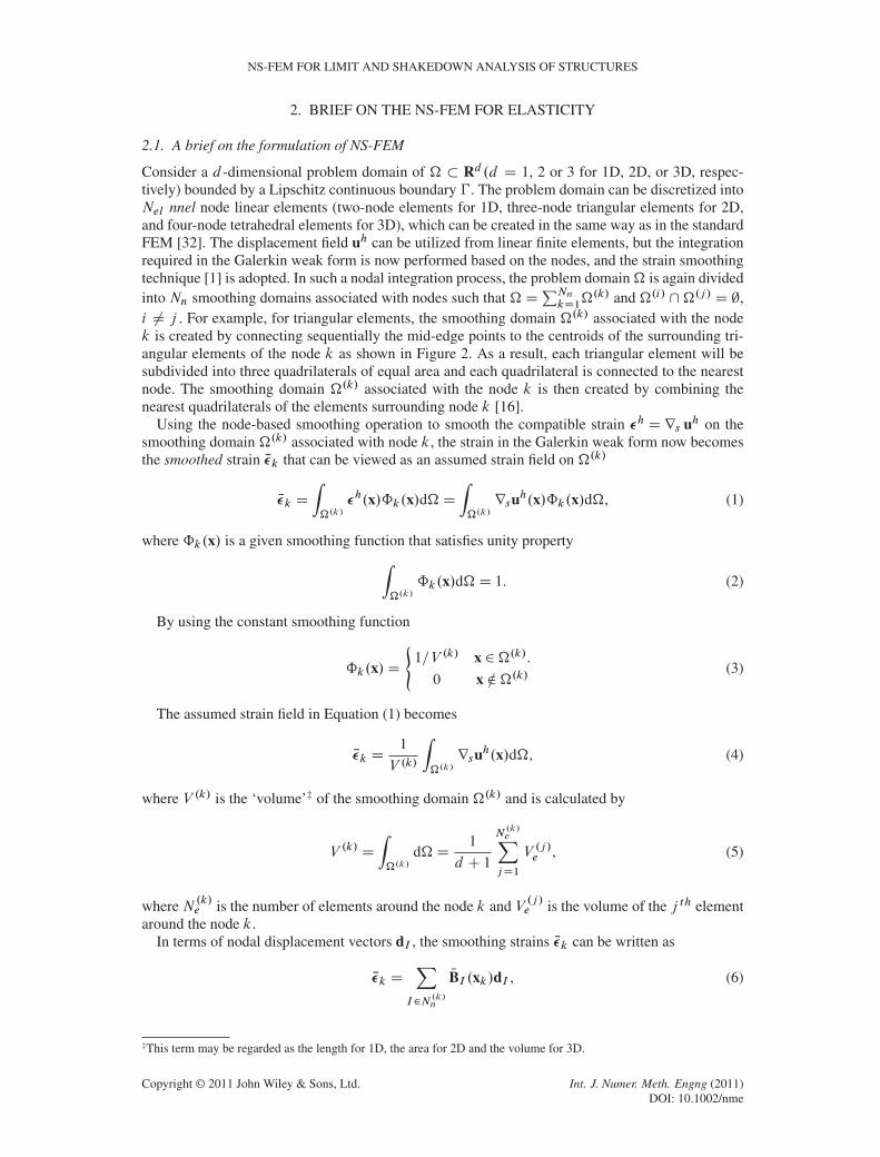
�.k/ and �.i/ \�.j / D ;,i ¤ j . For example, for triangular elements, the smoothing domain �.k/ associated with the nodek is created by connecting sequentially the mid-edge points to the centroids of the surrounding tri-angular elements of the node k as shown in Figure 2. As a result, each triangular element will besubdivided into three quadrilaterals of equal area and each quadrilateral is connected to the nearestnode. The smoothing domain �.k/ associated with the node k is then created by combining thenearest quadrilaterals of the elements surrounding node k [16].
Using the node-based smoothing operation to smooth the compatible strain �h Drs uh on thesmoothing domain �.k/ associated with node k, the strain in the Galerkin weak form now becomesthe smoothed strain N�k that can be viewed as an assumed strain field on �.k/
N�k D
Z�.k/
�h.x/ˆk.x/d�DZ�.k/rsuh.x/ˆk.x/d�, (1)
where ˆk.x/ is a given smoothing function that satisfies unity propertyZ�.k/
ˆk.x/d�D 1. (2)
By using the constant smoothing function
ˆk.x/D
(1=V .k/ x 2�.k/.
0 x …�.k/(3)
The assumed strain field in Equation (1) becomes
N�k D1
V .k/
Z�.k/rsuh.x/d�, (4)
where V .k/ is the ‘volume’‡ of the smoothing domain �.k/ and is calculated by
V .k/ D
Z�.k/
d�D1
d C 1
N.k/eXjD1
V .j /e , (5)
where N .k/e is the number of elements around the node k and V .j /e is the volume of the j th element
around the node k.In terms of nodal displacement vectors dI , the smoothing strains N�k can be written as
N�k DX
I2N.k/n
NBI .xk/dI , (6)
‡This term may be regarded as the length for 1D, the area for 2D and the volume for 3D.
Copyright © 2011 John Wiley & Sons, Ltd. Int. J. Numer. Meth. Engng (2011)DOI: 10.1002/nme

H. NGUYEN-XUAN ET AL.
where N .k/n is the number of nodes that are directly connected to node k as shown in Figure 2,
and NBI .xk/ is the smoothed strain-displacement matrix on the domain �.k/, which is calculatednumerically by an assembly process similar to the standard FEM
NBI .xk/D1
V .k/
N.k/eXjD1
1
d C 1V .j /e Bej , (7)
in which matrix Bej DPI2Se
jBI is the compatible strain-displacement matrix for the j th element
around the node k. It is assembled from the compatible strain-displacement matrices BI .x/ of nodesin the set Sej which contains nnel nodes of the j th linear element. Because linear elements are used,the entries of Bej are constants and therefore NBI .xk/ are also constants.
The smoothed stiffness matrix NK of the system is then assembled by a similar process as inthe FEM
NKIJ D
NnXkD1
NK.k/IJ , (8)
where NK.k/IJ is the smoothed stiffness matrix associated with node k and is calculated by
NK.k/IJ D
Z�.k/
NBTI C NBJ d�D NBTI C NBJV .k/ (9)
Note that because the smoothed strains N�k in Equation (1) are constants, the stresses N� k D C N�kare also constants in the smoothing domain �.k/.
2.2. Variational formulation of the NS-FEM
In this section, we show that the variational basis of the NS-FEM can be derived from the modifiedHellinger–Reissner variational principle [32]. The Hellinger–Reissner variational principle, wherethe stress field � and the displacement field u are often considered as two independent fields, iswritten as
…HR.� , u/DZ�
�� Trsu�
1
2� TC�1� � bT u
�d��
Z�t
NtT ud� . (10)
In the discretization form of a problem domain, Equation (10) can be expressed in a summationover all the smoothing domains as follows:
…HR.¢ , u/DNnXkD1
Z�.k/
�¢Trsu�
1
2¢TC�1¢
�d��
Z�.k/
bT ud��Z�.k/t
NtT ud�
!, (11)
where b is the body force and �.k/t is the portion of the element boundary over which prescribedsurface tractions Nt are applied.
If the stress field ¢ is now expressed through the stress–strain relation as ¢ D D N�k , the first termin the right-hand side of Equation (11) becomesZ
�.k/
�¢Trsu�
1
2¢TC�1¢
�d�D N�Tk C
Z�.k/rsud�„ ƒ‚ …
D N�kV.k/
�1
2N�Tk C N�kV
.k/ D1
2N�Tk C N�kV
.k/. (12)
Substituting Equation (12) into Equation (11), we obtain the two-field mixed principle based onthe smoothed strain N" and the displacement u as
…HR.N©, u/DNsXkD1
1
2N©Tk CN©kV
.k/ �
Z�.k/
bT ud��Z�.k/t
NtT ud�
!, (13)
Copyright © 2011 John Wiley & Sons, Ltd. Int. J. Numer. Meth. Engng (2011)DOI: 10.1002/nme

NS-FEM FOR LIMIT AND SHAKEDOWN ANALYSIS OF STRUCTURES
which can be considered as a special case of the mixed approach based on an assumed strain method[31]. This is because the present method only uses the displacements (one master field) as unknownsand the assumed strains are then defined by Equation (1), which can be expressed simply over onlydisplacement unknowns in Equation (6). It also implies that the NS-FEM has a foundation from theHellinger–Reissner variational principle, and it is variationally consistent [33].
2.3. A brief of properties of NS-FEM
The following properties of the NS-FEM were presented in [16,17]. In this paper, we only recall themain points that are effective for solving nonlinear problems in solid mechanics:
Property 1: NS-FEM can effectively alleviate volumetric locking.Property 2: NS-FEM possesses super-accurate and super-convergent properties of stress
solutions.Property 3: NS-FEM can directly compute the stress at nodes from the displacement solution
without using any post-processes.
The third property is similar to using just one Gauss point to compute the stress at nodes.The NS-FEM is hence very convenient for conducting the nonlinear computational algorithm usingthe stress at nodes and is more computationally efficient and simpler than the standard FEM usingthe stresses at Gauss points located inside the element. The next section therefore attempts to furtherformulate the NS-FEM for the limit and shakedown analysis of structures made of elastic–perfectlyplastic material. Note that linear finite elements (FEM-T3) have been shown to not be efficient forthe primal–dual algorithm while the following NS-FEM formulation, which is also built from linearfinite elements, works very well in finding the bounds of the load factor. In addition, it was recentlyshown by numerical examples for elastic results in [17,33] that the NS-FEM produces more accuratestresses and higher convergence rates (in the energy error norm) than the ES-FEM model. Hence, inthis paper, it will be also confirmed by numerical studies that the NS-FEM model can provide bettersolutions than the ES-FEM for the limit and shakedown analysis.
3. AN NS-FEM FORMULATION OF PRIMAL AND DUAL PROBLEMS IN LIMIT ANDSHAKEDOWN ANALYSIS
Let L be a convex polyhedral load domain that contains a special loading path consisting of all loadvertices OPi (i D 1, : : : ,m) of L [53, 64], where m is the number of load vertices. In the conformingFEM, the kinematical compatible conditions are satisfied. Hence, a strict dual bound of the plasticcollapse limit and the shakedown limit is achieved. However, in the NS-FEM, where the smoothingtechnique is used, the compatibility requirement is relaxed somewhat. It is therefore impossible toobtain strict dual formulations. This means the solutions obtained using the present method is onlyconsidered to be approximate upper and quasi-lower solutions. Let �E be the fictitious elastic stressvector. According to Koiter’s theorem [34], the upper bound shakedown limit, which is smallerto the low cycle fatigue limit and the ratcheting limit, may be found by minimizing the followingoptimization problem [63]:
˛C DminmXiD1
Z�
Dp. PN�ik/d� (a)
subjected to W
8̂̂̂ˆ̂̂̂̂̂<̂ˆ̂̂̂̂̂ˆ̂̂̂:
� N�k D
mXiD1
PN�ik , in� (b)
�uk D 0, on�u (c)
Dv PN�ik D 0, (d)mXiD1
Z�
PN�T
ik�Ek
�x, OPi
�d�D 1, (e)
(14)
Copyright © 2011 John Wiley & Sons, Ltd. Int. J. Numer. Meth. Engng (2011)DOI: 10.1002/nme

H. NGUYEN-XUAN ET AL.
where Dp. PN�ik/ is the plastic dissipation power per unit domain. The third constraint,Equation (14d), ensures that the incompressibility condition must be satisfied on all smoothingdomains �.k/ and at all load vertices i . Dv has the form
Dv D
24 1 1 0
1 1 0
0 0 0
35 for plane strain problems, and
Dv D
266666664
1 1 1 0 0 0
1 1 1 0 0 0
1 1 1 0 0 0
0 0 0 0 0 0
0 0 0 0 0 0
0 0 0 0 0 0
377777775
for 3D problems. (15)
By applying the strain smoothing technique on the smoothing domains associated with nodesin the NS-FEM presented in Section 2 and using von Mises yield criterion, Equation (14) can beexpressed through the discretized form of smoothing domains as follows:
˛C DminmXiD1
NnXkD1
V .k/
r2
3�y
pPN�T
ikD PN�ik C "20 (a)
subjected to W
8̂̂̂ˆ̂̂̂̂<ˆ̂̂̂̂̂ˆ̂:
mXiD1
PN�ik D NBk Pu, 8k D 1,Nn (b)
Dv PN�ik D 0, 8k D 1,Nn, 8i D 1,m (c)
mXiD1
NnXkD1
V .k/ PN�T
ik�Eik D 1, (d)
(16)
where �y is the yield stress and "20 is a small positive number that ensures that the objective functionis differentiable everywhere [57, 58], D is a diagonal square matrix with the following form:
DD diag�1 1
1
2
�for 2D problems, and
DD diag�1 1 1
1
2
1
2
1
2
�for 3D problems. (17)
For the sake of simplicity, some new notations are introduced
Peik D V.k/D1=2 PN©ik, tik D D�1=2¢Eik , OBk D V
.k/D1=2 NBk (18)
where Peik , tik , OBi are the new strain rate vector, new fictitious elastic stress vector, and new strainmatrix, respectively. By substituting Equation (18) into Equation (16), we obtain a simplified versionof the upper bound shakedown analysis (primal problem)
˛C DminmXiD1
NnXkD1
r2
3�y
qPeTikPeik C "2 (a)
subjected to W
8̂̂̂ˆ̂̂̂̂<ˆ̂̂̂̂̂ˆ̂:
mXiD1
Peik � OBk PuD 0, 8k D 1,Nn (b)
Dv Peik D 0, 8k D 1,Nn, 8i D 1,m (c)
mXiD1
NnXkD1
PeTiktik � 1D 0, (d)
(19)
Copyright © 2011 John Wiley & Sons, Ltd. Int. J. Numer. Meth. Engng (2011)DOI: 10.1002/nme

NS-FEM FOR LIMIT AND SHAKEDOWN ANALYSIS OF STRUCTURES
where "D V .k/"0 is also a small positive number.The Lagrange function associated with the primal problem (19) can be written as
LD
NnXkD1
(mXiD1
r2
3�y
qPeTikPeik C "2 �
mXiD1
”TikDv Peik � “Tk
mXiD1
Peik � OBk Pu
!)
� ˛
NnXkD1
mXiD1
PeTiktik � 1
!, (20)
in which ”ik ,ˇk ,˛ are Lagrange multipliers that take on the role of generalized stresses. As shownin [63], the dual problem of the primal problem (19) can be derived based on the Lagrange function(20), and has the following form:
˛� Dmax˛ (a)
subjected to W
8̂̂̂<ˆ̂̂:k”ik C “k C ˛tikk6
r2
3�y (b)
NnXkD1
OBTk “k D 0 (c)
(21)
where k�k denotes the Euclidean norm, that is, kvk D .vT v/1=2.The form (21) is also exactly the discretized form of the lower bound shakedown problem formu-
lated by Melan’s static theorem, while the Lagrange function (20) is an essential intermediate formto lead to the dual problem (21).
Note that the constraints (b), (c), and (d) in the primal problem (19) are related to kinematicvariables, while the constraints (b) and (c) in the dual problem (21) are related to static variables.Solving the primal problem (19) with kinematic variables will lead to an upper bound solution,while solving the dual problem (21) with static variables will lead to a lower bound solution. Theseupper and lower bounds are well known in the limit and shakedown analyses using FEM [45].
It is also noted that when the number of load vertices mD 1, the problems (19) and (21) ofshakedown analyses are reduced to those of limit analyses.
4. A PRIMAL–DUAL ALGORITHM FOR LIMIT AND SHAKEDOWN ANALYSIS
In principle, to obtain both upper and lower bounds, it is necessary to solve both primal and dualproblems independently. This requires a high computational cost. In addition, it takes more involve-ment to deal with the dual problem (21) related to the static variables [63]. In this section, we thussimplify the primal and dual algorithms [63, 64] using the NS-FEM model to obtain both approx-imate upper and quasi-lower bounds simultaneously by solving only the associated primal–dualform. The algorithm thus helps to reduce the computational cost significantly and avoid the difficul-ties related to the dual problem (21). In addition, our numerical approach is quite simple because ofthe use of just one Gauss point to compute the stress at nodes, which are also the smoothing domains.It was shown that the NS-FEM gains super-accurate and super-convergent solutions defined by nodalstresses. Hence, it is very efficient for conducting limit and shakedown nonlinear problems.
We introduce briefly the associated primal–dual form that has been shown to be more convenientfor large-scale optimization problems [57, 58, 64]. Now, a penalty function is used to eliminate thefirst two constraints in Equation (19) as follows:
P D
NnXkD1
8<:
mXiD1
qPeTikPeik C "2C
c
2
mXiD1
PeTikDv Peik Cc
2
mXiD1
Peik � OBk Pu
!T mXiD1
Peik � OBk Pu
!9=;,
(22)
Copyright © 2011 John Wiley & Sons, Ltd. Int. J. Numer. Meth. Engng (2011)DOI: 10.1002/nme

H. NGUYEN-XUAN ET AL.
where c is a penalty parameter fixed at 1e+10. Using Equation (22), the corresponding Lagrangefunction of Equation (19) becomes
LD P � ˛
NnXkD1
mXiD1
PeTiktik � 1
!. (23)
Similar to Equation (20), the Lagrange function (23) is also an essential intermediate form thatleads to the dual problem (21). Therefore, Equation (23) can be called ‘associated primal–dualform’.
By employing the Newton method to solve the Karush–Kuhn–Tucker (KKT) optimality condi-tions of the Lagrangian function in Equation (23), we obtain the Newton directions d Pu, dPeik , d� ik ,dˇk and d˛, which ensure that a suitable step along them will lead to a decrease in the objectivefunction of the primal problem (19) and to an increase in the objective function of the dual problem(21). If the relative improvement between two steps is smaller than a given constant, the algorithmstops and leads to the limit load factor ˛lim. More details of the computational algorithm can befound in [27].
It is noted that the assumed strains using the strain smoothing operator defined in Equation (1)relax the compatibility somewhat. Therefore, a strict upper bound cannot be ensured in general. Inaddition, the dual problem (21) is constructed from the primal problem (19) with Lagrange multipli-ers. Hence, a strict lower bound also cannot be guaranteed. Thus, the present method only providesapproximate upper and quasi-lower solutions of the plastic collapse limit and the shakedown limit.However, because only one Gaussian point is required for each smoothing domain in which strainrates are constant, the flow rule (or incompressibility condition in plane strain) is guaranteed to besatisfied everywhere in the problem domain. Therefore, the ‘upper’ and ‘lower’ bounds derived fromthe present method can still be reasonably considered as reliable bounds to the exact value.
5. NUMERICAL RESULTS
In this section, we examine the performance of the present primal–dual shakedown algorithm usingthe NS-FEM through a series of numerical examples. Various numerical examples are given tocompute both limit and shakedown load factors for structures. The structure can be discretized intoa mesh of T3 and T4 elements, and the present formulation corresponding to mesh types can betermed as NS-FEM-T3 and NS-FEM-T4, respectively. For each test case, some existing analyti-cal and numerical solutions found in literature are briefly presented and compared. In addition, theresults derived from the NS-FEM are also compared with those obtained from the ES-FEM model,which was found to be one of very effective and reliable numerical models using three-node lineartriangular elements [27]. Note that the NS-FEM and ES-FEM results given in Tables I and II wereobtained by averaging its upper and lower bound values at the final iteration.
5.1. Square plate with a central circular hole: convergence study of limit load factor
The first example deals with a square plate with a central circular hole, which is subjected tobiaxial uniform loads P1, P2, as shown in Figure 5(a). The given data is assumed as follows:E D 2.1� 105MPa, � D 0.3, �y D 200 MPa. The ratio between the diameter of the hole and theside length of the plate is 0.2 (R=LD 0.2/. This problem has then become the benchmark for vari-ous numerical models. Because of its symmetry, one-fourth of the plate is modeled and discretizedinto 512 triangular elements (289 nodes) and 1850 tetrahedral elements (624 nodes) as shown inFigures 5(b) and 10(b), respectively.
The aim of this example is to verify the convergence of NS-FEM solutions in comparison withthose of the FEM and ES-FEM. With P2 D 0, P1 2
�0, �y
and R=LD 0.2, the analytical solution
of the limit load factor using plane stress hypothesis and von Mises yield criterion was obtained byGaydon and McCrum [37] as
plim D .1�R=L/ �y D 0.8�y . (24)
Copyright © 2011 John Wiley & Sons, Ltd. Int. J. Numer. Meth. Engng (2011)DOI: 10.1002/nme

NS-FEM FOR LIMIT AND SHAKEDOWN ANALYSIS OF STRUCTURES
Table I. The limit load factor of the NS-FEM in comparison with those of other methods for the squareplate with a central circular hole.
Load cases
Authors and methods P1 D P2 P2 D P1=2 P2 D 0
Belytschko [43], equilibrium FE (LB) N/A N/A 0.780Nguyen and Palgen [45], equilibrium FE (LB) 0.704 N/A 0.564Genna [46], nonlinear inequality approach (LB) N/A N/A 0.793Gross-Weege [50], reduced basis technique (LB) 0.882 0.891 0.782Chen et al. [78], EFG (LB) 0.874 0.899 0.798Corradi and Zavelani [44], linear programming approach (LB) 0.767 N/A 0.691Vu [63], dual algorithm (UB) 0.895 N/A N/AZouain et al. [66], mixed model 0.894 0.911 0.803Zhang et al. [76] (3D case), BEM (LB) 0.889 0.898 0.784Zhang et al. [76] (2D case), BEM (LB) 0.893 0.907 0.789Tran et al. [27], dual algorithm 0.896 0.912 0.805Present (NS-FEM-T3), dual algorithm 0.894 0.911 0.802Present (NS-FEM-T4), dual algorithm 0.893 0.917 0.807Analytical [37] N/A N/A 0.8Analytical [37], LB 0.894 N/A N/AAnalytical [37], UB 0.924 N/A N/A
LB, lower bound; UB, upper bound.
Table II. The limit load factor of the NS-FEM in comparison with those of other methods for thin squareslabs with three different cutouts.
Model
(a) Circular (b) Square (c) CrackAuthors and methods cut-out cut-out cut-out
Zhang et al. [75], BEM (LB) 0.754 0.747 0.514Belytschko and Hodge [42], equilibrium FE (LB) 0.793 0.693 0.498Chen et al. [78], EFG (LB) 0.798 0.736 0.513Zhang et al. [47], iteration algorithm (UB) 0.824 0.764 0.534Tran et al. [27], dual algorithm 0.805 0.748 0.523Present (NS-FEM-T3), dual algorithm 0.802 0.741 0.519Present (NS-FEM-T4), dual algorithm 0.807 0.747 0.530
Numerical solutions obtained for FEM, ES-FEM, and NS-FEM models versus the increasing vari-ation of elements are shown in Figure 6. From these results, it can be observed that all numericallimit load factors converge to the exact one and NS-FEM can produce more accurate solutions thanFEM, mixed model [66], and ES-FEM.
The convergence rate is also illustrated in Figure 7. It can be observed that both NS-FEM and ES-FEM methods yield a super-convergent behaviour of the plastic limit load factor. This confirms thatthe super-convergence of solutions using S-FEM models can be obtained for plastic limit analysisproblems. Furthermore, the NS-FEM exhibits the most accurate results.
Figure 8 illustrates the limit load domains using the NS-FEM and several other methods. It canbe seen that NS-FEM solutions agree very well with those of the lower bound approach in [43, 50]and the upper bound approach in [52]. Note that the ES-FEM also shows very accurate results forthis problem.
Table I further shows the limit load factor of the NS-FEM in comparison with those of othermethods. It can again be seen that the NS-FEM solutions agree very well with those of the otherexisting FEM and meshfree models. In particular, the NS-FEM produces solutions that are veryclose to those of the mixed formulation in [66], and even achieves higher accuracy in the load caseP2 D 0, even though our model uses only 544 DOFs compared with 2014 DOFs in [66]. For the3D model, it can also be seen that the results of the present element show very good agreement withother available ones.
Copyright © 2011 John Wiley & Sons, Ltd. Int. J. Numer. Meth. Engng (2011)DOI: 10.1002/nme

H. NGUYEN-XUAN ET AL.
(a)
0 1 2 3 4 50
0.5
1
1.5
2
2.5
3
3.5
4
4.5
5
(b)
Figure 5. Square plate with a central circular hole: (a) full model subjected to biaxial uniform loads and(b) its quarter model with symmetric conditions imposed on the left and bottom edges, and the finite element
discretization using 512 three-node linear triangular elements.
0 100 200 300 400 500 600
0.8
0.805
0.81
0.815
0.82
0.825
0.83
0.835
Number of elements
Load
fact
or
Exact sol.Mixed modelFEM−T3ES−FEM−T3NS−FEM−T3
Figure 6. Convergence of limit load factor (with P2= 0) of the NS-FEM-T3 in comparison with those ofother methods for the square plate with a central circular hole.
5.2. Thin square slabs with three different cutouts subjected to tension: accuracy study of limitload factor
We next assess the performance of the NS-FEM via the limit analysis of the thin square slabs withthree different cutouts (circular, square, and crack cutouts) subjected to tension, as shown in Figure 9
Copyright © 2011 John Wiley & Sons, Ltd. Int. J. Numer. Meth. Engng (2011)DOI: 10.1002/nme

NS-FEM FOR LIMIT AND SHAKEDOWN ANALYSIS OF STRUCTURES
−0.8 −0.7 −0.6 −0.5 −0.4 −0.3 −0.2 −0.1 0 0.1−1
−0.8
−0.6
−0.4
−0.2
0
0.2
0.4
0.6
0.8
log10
(h)
log 10
(Rel
ativ
e er
ror
in c
olla
pse
load
)
FEM−T3ES−FEM−T3NS−FEM−T3 1.01
1.44
1.53
Figure 7. Convergence rate of limit load factor (with P2= 0) of the NS-FEM-T3 in comparison with thoseof FEM-T3 and ES-FEM-T3 methods for the square plate with a central circular hole.
0 0.2 0.4 0.6 0.8 10
0.1
0.2
0.3
0.4
0.5
0.6
0.7
0.8
0.9
1
P1/σ
s
P2/σ
s
NS−FEM−T3ES−FEM−T3Belytschko, lower bound HF Chen et al, upper boundGross−Weege, lower bound
NS−FEM−T3
Figure 8. The limit load domain of the NS-FEM-T3 in comparison with those of other methods for thesquare plate with a central circular hole.
a) circular cutout b) square cutout c) crack cutout
Figure 9. Thin square slabs with three different cut-outs.
Copyright © 2011 John Wiley & Sons, Ltd. Int. J. Numer. Meth. Engng (2011)DOI: 10.1002/nme

H. NGUYEN-XUAN ET AL.
[42]. The given data are selected as in Section 5.1. This plane stress problem has been solved numer-ically by finite element [42, 47], BEM [75], and recently by the element-free Galerkin method [78].Because of their symmetry, only the quadrants of three slabs are modeled and their discretizationsusing three-node linear triangular elements are shown in Figure 10.
Table II shows the limit load factors of the NS-FEM in comparison with those of several differentlimit analysis approaches, and Figure 11 illustrates simultaneously both the upper and lower boundsof the limit load factors for three cases of slabs. Using the primal–dual algorithm, all the upper andlower bounds for three cases of slabs in Figure 11 converge rapidly to the solutions given in Table II.Moreover, NS-FEM-T3 solutions are slightly more accurate than those of ES-FEM-T3.
0 1 2 3 4 50
0.5
1
1.5
2
2.5
3
3.5
4
4.5
5
(a) 0
12
34
5
0
1
2
3
4
5
00.20.4
(b) Circular cutout
−1.5 −1 −0.5 0 0.5
−0.5
0
0.5
1
1.5
(c) −2
−1.5−1
−0.50
0.51
−1
−0.5
0
0.5
1
1.5
2
00.20.4
(d) Square cutout
0 0.5 1 1.5 2 2.50
0.5
1
1.5
2
2.5
(e) 0
0.5
1
1.5
2
2.5
0
0.5
1
1.5
2
2.5
00.20.4
(f) Crack cutout
Figure 10. Finite element discretization using three-node linear triangular and four-node linear tetrahedralelements for thin square slabs with three different cut-outs.
Copyright © 2011 John Wiley & Sons, Ltd. Int. J. Numer. Meth. Engng (2011)DOI: 10.1002/nme

NS-FEM FOR LIMIT AND SHAKEDOWN ANALYSIS OF STRUCTURES
(a) circular
cutout 1 2 3 4 5 6 7 8 9
0.45
0.5
0.55
0.6
0.65
0.7
0.75
0.8
0.85
0.9
Iterations
Load
fact
or
Zhang et al., BEM (LB)Belytschko, Equilibrium FE (LB)Chen et al., EFG (LB)Zhang et al., Displacement FE (UB)NS−FEM−T3, Primal approachNS−FEM−T3, Dual approachES−FEM−T3, Primal approachES−FEM−T3, Dual approach
NS−FEM−T3
NS−FEM−T3
(b) square
cutout1 2 3 4 5 6 7 8 9 10 11
0.4
0.45
0.5
0.55
0.6
0.65
0.7
0.75
0.8
Iterations
Load
fact
or
Zhang et al., BEM (LB)Belytschko, Equilibrium FE (LB)Chen et al., EFG (LB)Zhang et al., Displacement FE (UB)NS−FEM−T3, Primal approachNS−FEM−T3, Dual approachES−FEM−T3, Primal approachES−FEM−T3, Dual approach
NS−FEM−T3
NS−FEM−T3
(c) crack
cutout 1 2 3 4 5 6 7 8
0.35
0.4
0.45
0.5
0.55
0.6
0.65
Iterations
Load
fact
or
Zhang et al., BEM (LB)Belytschko, Equilibrium FE (LB)Chen et al., EFG (LB)Zhang et al., Displacement FE (UB)NS−FEM−T3, Primal approachNS−FEM−T3, Dual approachES−FEM−T3, Primal approachES−FEM−T3, Dual approach
Figure 11. Convergence of limit load factors using the NS-FEM-T3 solution in comparison with those ofother methods for thin square slabs with three different cut-outs: (a) circular; (b) square; and (c) crack.
Also from Figure 11 and Table II, it can be seen that the solutions of the NS-FEM are lower thanthose of the upper bound models and higher than those of the lower bound approaches. This impliesthat the NS-FEM can produce results that are closer to the exact value than several other methodsin the literature.
Copyright © 2011 John Wiley & Sons, Ltd. Int. J. Numer. Meth. Engng (2011)DOI: 10.1002/nme

H. NGUYEN-XUAN ET AL.
5.3. Asymmetrical cantilever model
Consider a clamped tapered cantilever subjected to an in-plane shearing load stress, as shown inFigure 12(a). The given data is assumed as follows: E D 2.1� 105MPa, � D 0.3, �y D
p3 MPa.
The problem domain is modeled and discretized into 1152 triangular elements (625 nodes) and 3456tetrahedral elements (1082 nodes), as shown in Figures 12(b) and (c), respectively. The exact solu-tion of this problem is unknown. The reference value found in [73] was 0.68504, which was obtainedby averaging upper and lower bounds at the last adaptive refinement step. This problem was theninvestigated in [15] using the CS-FEM-Q4 scheme, which led to the solution of 0.6852. Figure 13plots the limit load factors of ES-FEM and NS-FEM using the primal–dual algorithm. The obtainedsolutions are reasonable in comparison with the reference value. For instance, in comparison withthe reference value, the present approach using the NS-FEM-T4 model produces an approximateupper bound of 0.6857 (more than 0.096%) and a quasi-lower bound of 0.6832 (less than 0.269%)at the last iteration.
(a)
0 1 2 3 4 50
1
2
3
4
5
6
(b)
(c)
c)
0
1
2
3
4
5 0
1
2
3
4
5
6
00.20.4
Figure 12. Asymmetrical cantilever problem: (a) 3D model; (b) 2D mesh; and (c) 3D mesh.
Copyright © 2011 John Wiley & Sons, Ltd. Int. J. Numer. Meth. Engng (2011)DOI: 10.1002/nme

NS-FEM FOR LIMIT AND SHAKEDOWN ANALYSIS OF STRUCTURES
2 4 6 8 10 120.5
0.55
0.6
0.65
0.7
0.75
Iterations
Load
fact
or
Ref sol.ES−FEM−T3, Primal approachES−FEM−T3, Dual approachNS−FEM−T3, Primal approachNS−FEM−T3, Dual approachNS−FEM−T4, Primal approachNS−FEM−T4, Dual approach
Figure 13. The limit load factor of asymmetrical cantilever problem.
Table III. Elastic shakedown load factors for the square plate problem with a central circular hole with2R=LD 0.2 subjected to independently varying loads.
Authors and methods P1 D P2 P2 D P1=2 P2 D 0
Nguyen and Palgen [45], equilibrium FE (LB) 0.431 0.514 0.557Belytschko [43], equilibrium FE (LB) 0.431 0.501 0.571Zhang [49], LB 0.431 0.514 0.596Zhang et al. [76] (3D case), LB 0.467 0.538 0.634Zhang et al. [76] (2D case), LB 0.477 0.549 0.647Genna [46], nonlinear inequality approach (LB) 0.478 0.566 0.653Liu et al. [77], BEM (LB) 0.477 0.549 0.647Gross-Weege [50], reduced basis technique (LB) 0.446 0.524 0.614Zhang [49], upper bound 0.453 0.539 0.624Corradi and Zavelani [44], linear programming approach (UB) 0.504 0.579 0.654Carvelli et al. [53], UB 0.518 6.07 0.696Zhang and Raad [65], eigen-mode method 0.494 N/A 0.574Zouain et al. [66], mixed approach 0.429 0.500 0.594Krabbenhøft et al. [68], adaptive approach 0.430 0.499 0.595Garcea et al. [67], iterative method 0.438 0.508 0.604Tran et al. [27], dual algorithm 0.444 0.514 0.610Present (NS-FEM-T3) 0.439 0.508 0.601Present (NS-FEM-T4) 0.428 0.495 0.588
5.4. Square plate with a central circular hole: convergence and accuracy study of shakedownload factor
Now we perform the shakedown analysis for the square plate problem with a central circular hole, asshown in Section 5.1, by using the NS-FEM-T3 and NS-FEM-T4. The exact solution of this prob-lem is not available and the first numerical study on this problem was performed by Belytschko andHodge [43]. Many authors have then chosen this benchmark as a numerical base to verify numericalshakedown approaches. Among these numerical approaches, an adaptive finite element formulationby Krabbenhøft et al. [68] was found to be the most effective.
Table III shows the numerical results of elastic shakedown load factors of the NS-FEM in com-parison with other methods. It can be seen that the numerical results show a relatively large scatter.In general, NS-FEM results agree well with the available numerical results. As compared withthe adaptive solution in [68], the difference is about 0.5% to 2.2%, 0.8% to 1.7%, and 0.8% to1.1% for load cases of P1 D P2, P2 D P1=2, and P2 D 0, respectively. These errors are quite small
Copyright © 2011 John Wiley & Sons, Ltd. Int. J. Numer. Meth. Engng (2011)DOI: 10.1002/nme

H. NGUYEN-XUAN ET AL.
and reasonable, even though we only use the uniform mesh of three-node linear triangular ele-ments. Therefore, NS-FEM is very promising in providing a simple and effective tool for limit andshakedown analyses of structures in applications.
5.5. Grooved rectangular plate subjected to varying tension and bending
This example considers a grooved rectangular plate subjected to in-plane tension pN and bendingpM (Figure 14(a)). The load domain is defined by
pM 2�0, �y
,pN 2
�0, �y
(31)
First, limit analysis of this problem for pure tension load case, pN ¤ 0, pM D 0 has been studiedby several authors such as Prager and Hodge [36], Casciaro and Cascini [41], and Yan [51]. Furtherinvestigations for a more complicated case with pN ¤ 0, pM ¤ 0 were then reported by Vu [63]and Tran et al. [27, 72]. The structure is discretized into 720 three-node triangular elements (T3) asshown in Figure 14(b). The following data are used: R D 250mm,L D 4R, E D 2.1 � 105MPa,� D 0.3, �y D 116.2MPa.
Table IV shows the limit load factor for constant pure tension case, pN D �y ,pM D 0 of theNS-FEM in comparison with those of other methods. It can be seen that NS-FEM solutions agreewell with the other existing solutions for both plane stress and plane strain assumptions. On thebasis of the von Mises yield criterion, it can also be seen that the NS-FEM can produce solutionsbelonging to the reliable interval of the analytical approach by Yan [51].
Limit and shakedown analysis is also investigated for the case of having both in-plane tension andbending. Figure 15 shows the convergence of limit and shakedown load factors of the NS-FEM incomparison with those of ES-FEM [27]. In the case of limit analysis, the load factors of the ES-FEMand NS-FEM are, respectively, 0.3003 and 0.2966, which are quite close to the 0.30498 obtainedby Tran [72]. In the case of shakedown analysis, the load factors of ES-FEM and NS-FEM are,respectively, 0.23461 and 0.22477, which are also quite close to the 0.23494 obtained by Vu [63].The NS-FEM results are slightly more accurate than those of the upper bounds in [63, 72].
0 1 2 3 40
0.5
1
1.5
2
2.5
3
3.5
4
(a) (b)
Figure 14. A grooved rectangular plate subjected to in-plane tension pN and bending pM : (a) modelincluding loads and boundary conditions and (b) finite element discretization using 720 three-node linear
triangular elements.
Copyright © 2011 John Wiley & Sons, Ltd. Int. J. Numer. Meth. Engng (2011)DOI: 10.1002/nme

NS-FEM FOR LIMIT AND SHAKEDOWN ANALYSIS OF STRUCTURES
Table IV. Limit load factor for constant pure tension case, pN D �y ,pM D 0, of the grooved rectangularplate.
Plane stress Plane strain Nature of solution Yield criterion
Prager and Hodge [36] 0.500 0.630–0.695 analytical TrescaCasciaro and Cascini [41] 0.568 0.699 numerical von MisesYan [51] 0.500–0.577 0.727–0.800 analytical von MisesYan [51] 0.558 0.769 numerical von MisesVu [63] 0.557 0.799–0.802 numerical von MisesTran [72] 0.572 — numerical von MisesTran et al. [27] 0.562 0.768 numerical von MisesNS-FEM-T3 0.559 0.734 numerical von Mises
(a) limit analysis1 2 3 4 5 6 7 8 9
0.2
0.25
0.3
0.35
0.4
Iterations
Load
fact
orNS−FEM−T3, Primal approachNS−FEM−T3, Dual approachES−FEM−T3, Primal approachNS−FEM−T3, Dual approach
(b) shakedown analysis
1 2 3 4 5 6 7 8 9 10
0.2
0.25
0.3
0.35
0.4
0.45
Iterations
Load
fact
or
NS−FEM−T3, Primal approachNS−FEM−T3, Dual approachES−FEM−T3, Primal approachNS−FEM−T3, Dual approach
Figure 15. Convergence of load factors for the grooved rectangular plate.
5.6. A symmetric continuous beam
The last problem is a symmetric continuous beam subjected to two independent loads depicted inFigure 16. The material parameters are: E D 1.8 � 105 MPa, � D 0.3, �y D 100 MPa. The loaddomains were chosen analogously as in [67]: 1.2 MPa 6 p1 6 2.0 MPa, 0 6 p2 6 1.0MPa. Thefinite element discretization using 1200 (T3) elements is described in Figure 16(b). The limit andshakedown values are presented in Table V. It can be seen that the shakedown factor is differentfrom the alternating plasticity value. Hence, nonadaptation occurs because of incremental plasticity(ratcheting), as already pointed out in [67]. The convergence of limit and shakedown load factors
Copyright © 2011 John Wiley & Sons, Ltd. Int. J. Numer. Meth. Engng (2011)DOI: 10.1002/nme

H. NGUYEN-XUAN ET AL.
(a)
0 50 100 1500
5
10
15
20
(b)
Figure 16. Symmetric continuous beam: (a) the geometry and (b) finite element discretization using 1200three-node linear triangular elements.
Table V. Limit and shakedown load factor for the symmetric continuous beam.
Limit analysis Shakedown analysis
(p1,p2) (2, 0) (0, 1) (1.2, 1) (2, 1) Alternating Ratcheting[MPa] plasticity
[67] 3.280 8.718 5.467 3.280 5.304 3.244ES-FEM-T3 3.402 9.192 5.720 3.386 5.451 3.373NS-FEM-T3 3.297 8.722 5.493 3.296 4.914 3.259
1 2 3 4 5 6 7 8 9 10 11 121.5
2
2.5
3
3.5
4
4.5
Iterations
Load
fact
or
Primal approach − LimitDual approach − LimitPrimal approach − ShakedownDual approach − ShakedownGarcea et al. − ShakedownChen et al. − Shakedown
Figure 17. Continuous beam: convergence of limit and shakedown load factors in comparison with those oftwo other methods.
in comparison with those of two other methods are described in Figure 17. The obtained solutionsagree well with the published results in [67, 79]. Finally, Table VI closes the shakedown solutionsof this problem with various load domains.
Copyright © 2011 John Wiley & Sons, Ltd. Int. J. Numer. Meth. Engng (2011)DOI: 10.1002/nme

NS-FEM FOR LIMIT AND SHAKEDOWN ANALYSIS OF STRUCTURES
Table VI. Shakedown load factor of the symmetric continuous beam with variousload domains.
Shakedown load factor
Case Load domain (MPa) [67] [79] Present
1 1.26 p1 6 2.0 3.244 3.297 3.25906 p2 6 1.0
2 06 p1 6 2.0 — 2.174 2.0360.66 p2 6 1.0
3 06 p1 6 2.0 — 2.152 2.01606 p2 6 1.0
6. CONCLUSIONS
A simple and effective numerical procedure for limit and shakedown analysis of structures usingthe NS-FEM has been investigated in this paper. A primal–dual algorithm based on the von Misesyield criterion and a Newton iterative method were combined to determine simultaneously bothapproximate upper and quasi-lower bounds of the plastic collapse limit and the shakedown limit bysolving only the associated primal–dual form. The numerical solutions of predicting both limit andshakedown load factors were obtained for structures Through the problems tested, some concludingremarks can be made as follows:
(1) The NS-FEM uses only three DOFs at each vertex node without additional DOFs. In addition,the stress is computed directly from the displacement solutions without using any post-process in the NS-FEM. This is similar to using just one Gauss point to compute the stressat nodes, which are also the smoothing domains. This not only guarantees a minimum num-ber of the total variables in the resulting optimization problem, but also helps to increasecomputational efficiency of the NS-FEM.
(2) At each iteration, both the quasi-lower bound and the approximate upper bound were calcu-lated simultaneously with no extra computational cost. This calculation is thus promisingin providing an effective tool to estimate the accuracy of the solution and to ensure theconvergence of the present formulation.
(3) By using the Newton iterative method, the nonlinear optimization analysis is reduced to someiterations of the linear elastic analyses and hence there is no limit in practical applications.In addition, the actual Newton directions updated at each iteration will ensure the kinematicalconditions of the displacements to be satisfied automatically.
(4) Numerical solutions of the NS-FEM are, in general, closer to the exact solutions thanthe results of the ES-FEM and show good agreement with several results available inthe literature. Also, the present approach behaves much better than the ES-FEM withincompressibility.
(5) The extension of the NS-FEM formulation to the limit and shakedown analysis of 3Dproblems is straightforward, while the ES-FEM is only available for 2D problems.
(6) Although the 3D problems tested here are extruded by 2D cases, the present formulation isgeneral and hence can perform well for more complicated 3D structures.
However, the present algorithm still remains a limitation when solving large-scale problems thatare increasing in engineering practice using our present package. It is therefore very useful to asso-ciate the proposed procedure with the MOSEK software package. It would also be interesting toassociate the present method with an adaptive local refinement procedure to enhance the accuracyof solutions at a suitable cost.
In addition to the above discussions, the authors believe that the method presented herein can bevery promising to:
(1) improve the load factor solution of limit and shakedown problems with strong discontinu-ities [81–83] in fracture structures by coupling the NS-FEM to the extended FEM (XFEM)[84–86]; and
Copyright © 2011 John Wiley & Sons, Ltd. Int. J. Numer. Meth. Engng (2011)DOI: 10.1002/nme

H. NGUYEN-XUAN ET AL.
(2) apply the NS-FEM to a staggered gradient elasticity formulation for the accounting of theeffects of microstructure of materials and structures [87, 88].
ACKNOWLEDGEMENT
The support of the Vietnam National Foundation for Science and Technology Development (NAFOSTED;Grant No. 107.02-2010.05) is gratefully acknowledged.
REFERENCES
1. Chen JS, Wu CT, Yoon S, You Y. A stabilized conforming nodal integration for Galerkin mesh-free methods.International Journal for Numerical Methods in Engineering 2001; 50:435–466.
2. Liu GR, Dai KY, Nguyen-Thoi T. A smoothed finite element for mechanics problems. Computational Mechanics2007; 39:859–877.
3. Liu GR, Nguyen-Thoi T, Dai KY, Lam KY. Theoretical aspects of the smoothed finite element method (SFEM).International Journal for Numerical Methods in Engineering 2007; 71:902–930.
4. Nguyen-Xuan H, Bordas S, Nguyen-Dang H. Smooth finite element methods: Convergence, accuracy and properties.International Journal for Numerical Methods in Engineering 2008; 74:175–208.
5. Liu GR, Nguyen-Thoi T, Nguyen-Xuan H, Dai KY, Lam KY. On the essence and the evaluation of the shape func-tions for the smoothed finite element method(SFEM). International Journal for Numerical Methods in Engineering2009; 77:1863–1869.
6. Dai KY, Liu GR, Nguyen-Thoi T. An n-sided polygonal smoothed finite element method (nSFEM) for solidmechanics. Finite Element Analysis and Design 2007; 43:847–860.
7. Dai KY, Liu GR. Free and forced vibration analysis using the smoothed finite element method (SFEM). Journal ofSound and Vibration 2007; 301:803–820.
8. Nguyen-Thoi T, Liu GR, Dai KY, Lam KY. Selective Smoothed Finite Element Method. Tsinghua Science andTechnology 2007; 12(5):497–508.
9. Nguyen-Xuan H, Bordas S, Nguyen-Dang H. Addressing volumetric locking and instabilities by selective integrationin smoothed finite elements. Communications in Numerical Methods in Engineering 2009; 25:19–34.
10. Nguyen-Xuan H, Rabczuk T, Bordas S, Debongnie JF. A smoothed finite element method for plate analysis.Computer Methods in Applied Mechanics and Engineering 2008; 197:1184–1203.
11. Nguyen-Thanh N, Rabczuk T, Nguyen-Xuan H, Bordas S. A smoothed finite element method for shell analysis.Computer Methods in Applied Mechanics and Engineering 2008; 198:165–177.
12. Nguyen-Xuan H, Nguyen-Thoi T. A stabilized smoothed finite element method for free vibration analysis ofMindlin-Reissner plates. Communications in Numerical Methods in Engineering 2009; 25(8):882–906.
13. Bordas S, Rabczuk T, Nguyen-Xuan H, Nguyen Vinh P, Natarajan S, Bog T, Do Minh Q, Nguyen Vinh H. Strainsmoothing in FEM and XFEM. Computers and Structures 2010; 88(23–24):1419–1443.
14. Bordas S, Natarajan S, Kerfriden P, Augarde CE, Mahapatra DR, Rabczuk T, Pont SD. On the performance of strainsmoothing for quadratic and enriched finite element approximations (XFEM/GFEM/PUFEM). International Journalfor Numerical Methods in Engineering 2011; 86(4–5):637–666.
15. Le CV, Nguyen-Xuan H, Askes H, Bordas S, Rabczuk T, Nguyen-Vinh H. A cell-based smoothed finite ele-ment method for kinematic limit analysis. International Journal for Numerical Methods in Engineering 2010;88(12):1651–1674.
16. Liu GR, Nguyen-Thoi T, Nguyen-Xuan H, Lam KY. A node-based smoothed finite element method (NS-FEM) forupper bound solutions to solid mechanics problems. Computers and Structures 2009; 87:14–26.
17. Nguyen-Thoi T, Liu GR, Nguyen-Xuan H. Additional properties of the node-based smoothed finite element method(NS-FEM) for solid mechanics problems. International Journal of Computational Methods 2009; 6:633–666.
18. Nguyen-Thoi T, Liu GR, Nguyen-Xuan H, Nguyen Tran C. Adaptive analysis using the node-based smoothed finiteelement method (NS-FEM). Communications in Numerical Methods in Engineering 2010; 27(2):198–218.
19. Nguyen-Thoi T, Vu-Do HC, Rabczuk T, Nguyen-Xuan H. A node-based smoothed finite element method (NS-FEM)for upper bound solution to visco-elastoplastic analyses of solids using triangular and tetrahedral meshes. ComputerMethods in Applied Mechanics and Engineering 2010; 199:3005–3027.
20. Liu GR, Chen L, Nguyen-Thoi T, Zeng K, Zhang GY. A novel singular node-based smoothed finite elementmethod (NS-FEM) for upper bound solutions of fracture problems. International Journal for Numerical Methodsin Engineering 2010; 83(11):1466—1497.
21. Nguyen-Xuan H, Rabczuk T, Nguyen-Thanh N, Nguyen-Thoi T, Bordas S. A node-based smoothed finite ele-ment method with stabilized discrete shear gap technique for analysis of Reissner–Mindlin plates. ComputationalMechanics 2010; 46(5):679–701.
22. Nguyen-Xuan H, Tran LV, Nguyen-Thoi T, Vu-Do HC. Analysis of functionally graded plates using an edge-basedsmoothed finite element method. Composite Structures 2011. DOI: 10.1016/j.compstruct.2011.04.028. in press.
23. Liu GR, Nguyen-Thoi T, Lam KY. An edge-based smoothed finite element method (ES-FEM) for static, free andforced vibration analyses of solids. Journal of Sound and Vibration 2009; 320:1100–1130.
24. Nguyen-Xuan H, Liu GR, Nguyen-Thoi T, Nguyen Tran C. An edge-based smoothed finite element method (ES-FEM) for analysis of two-dimensional piezoelectric structures. Smart and Material Structures 2009; 18(6):065015.
Copyright © 2011 John Wiley & Sons, Ltd. Int. J. Numer. Meth. Engng (2011)DOI: 10.1002/nme

NS-FEM FOR LIMIT AND SHAKEDOWN ANALYSIS OF STRUCTURES
25. Nguyen-Xuan H, Liu GR, Thai-Hoang C, Nguyen-Thoi T. An edge-based smoothed finite element method with stabi-lized discrete shear gap technique for analysis of Reissner-Mindlin plates. Computer Methods in Applied Mechanicsand Engineering 2010; 199:471–489.
26. Nguyen-Thoi T, Liu GR, Vu Do HC, Nguyen-Xuan H. An edge-based smoothed finite element method (ES-FEM)for visco-elastoplastic analyses of 2D solids using triangular mesh. Computational Mechanics 2009; 45:23–44.
27. Tran TN, Liu GR, Nguyen-Xuan H, Nguyen-Thoi T. An edge-based smoothed finite element method for primal-dualshakedown analysis of structures. International Journal for Numerical Methods in Engineering 2010; 82:917–938.
28. Nguyen-Thoi T, Liu GR, Lam KY. A face-based smoothed finite element method (FS-FEM) for 3D linear and non-linear solid mechanics problems using 4-node tetrahedral elements. International Journal for Numerical Methods inEngineering 2009; 78(3):324–353.
29. Nguyen-Thoi T, Liu GR, Vu Do HC, Nguyen-Xuan H. A face-based smoothed finite element method (FS-FEM)for visco-elastoplastic analyses of 3D solids using tetrahedral mesh. Computer Methods in Applied Mechanics andEngineering 2009; 198(41–44):3479–3498.
30. Liu GR, Nguyen-Thoi T. Smoothed Finite Element Methods. CRC Press, Taylor and Francis Group: NewYork, 2010.31. Simo JC, Hughes TJR. On the variational foundation of assumed strain methods. ASME Journal of Applied
Mechanics 1986; 53:51–54.32. Zienkiewicz OC, Taylor RL. The finite element method, (5th edn), Vol. 1. Butterworth Heinemann: Oxford, 2000.33. Liu GR, Nguyen-Xuan H, Nguyen-Thoi T. A theoretical study on NS/ES-FEM: properties, accuracy and convergence
rates. International Journal for Numerical Methods in Engineering 2010; 84:1222–1256.34. Koiter WT. General theorems for elastic plastic solids. In Progress in Solid Mechanics, Sneddon IN, Hill R (eds).
Nord-Holland: Amsterdam, 1960. 165–221.35. Melan E. Theorie statisch unbestimmter Systeme aus ideal plastischem. Baustoff. Sitzber. Akad. Wiss, Wien IIa 1936;
145:195–218.36. Prager W, Hodge PGJr. Theory of perfectly plastic solids. Wiley: New York, 1951.37. Gaydon FA, McCrum AW. A theoretical investigation of the yield point loading of a square plate with a central
circular hole. Journal of Mechanics and Physics Solids 1951; 2:156–169.38. Krabbenhoft K, Lyamin AV, Hjiaj M, Sloan SW. A new discontinuous upper bound limit analysis formulation.
International Journal for Numerical Methods in Engineering 2005; 63:1069–1088.39. Smith CC, Gilbert M. Application of Discontinuity Layout Optimization to Plane Plasticity Problems. Proceedings
of the Royal Society A: Mathematical, Physical and Engineering Sciences 2007; 463:2461–2484.40. Gilbert M, Smith CC, Pritchard TJ. Masonry arch analysis using discontinuity layout optimization. Proceedings of
the Institution of Civil Engineers - Engineering and Computational Mechanics 2010; 163(3):155–166.41. Casciaro R, Cascini L. A mixed formulation and mixed finite elements for limit analysis. International Journal for
Numerical Methods in Engineering 1982; 18:211–243.42. Belytschko T, Hodge PG. Plane stress limit analysis by finite element. Journal of Engineering Mechanics Division
1970; 96:931–944.43. Belytschko T. Plane stress shakedown analysis by finite elements. International Journal of Mechanic Sciences 1972;
14:619–625.44. Corradi L, Zavelani A. A linear programming approach to shakedown analysis of structures. Computer Methods in
Applied Mechanics and Engineering 1974; 3:37–53.45. Nguyen DH, Palgen L. Shakedown analysis by displacement method and equilibrium finite elements. Proceedings
of SMIRT-5, Berlin, 1979. Paper L3/3.46. Genna F. A nonlinear inequality, finite element approach to the direct computation of shakedown load safety factors.
International Journal of Mechanics and Sciences 1988; 30:769–789.47. Zhang P, Lu MW, Hwang KC. A mathematical programming algorithm for limit analysis. Acta Mechanics Sinica
1991; 7:267–274.48. Stein E, Zhang G. Shakedown with nonlinear strain-hardening including structural computation using finite element
method. International Journal of Plasticity 1992; 8:1–31.49. Zhang G. Einspielen und dessen numerische Behandlung von Flachentragwerken aus ideal plastischem bzw.
Kinematisch verfestingendemMaterial, Berich-nr. F92/i. Institut für Mechanik, University Hannover, 1995.50. Gross-Weege J. On the numerical assessment of the safety factor of elasto-plastic structures under variable loading.
International Journal of Mechanics and Sciences 1997; 39:417–433.51. Yan AM. Contribution to the direct limit state analysis of plastified and cracked structures. Dissertation, Université
de Liège, Belgium, 1997.52. Chen HF, Liu YH, Cen ZZ, Xu BY. On the solution of limit load and reference stress of 3-D structures under
multi-loading systems. Engineering Structures 1999; 21:530–537.53. Carvelli V, Cen ZZ, Liu Y, Maier G. Shakedown analysis of defective pressure vessels by a kinematic approaches.
Archive of Applied Mechanics 1999; 69:751–764.54. Huh H, Yang WH. A general algorithm for limit solutions of plane stress problems. Journal of Solids and Structures
1991; 28:727–738.55. Zouain N, Herskovits J, Borges LA, Feijoo RA. An iterative algorithm for limit analysis with nonlinear yield
functions. Journal of Solids and Structures 1993; 30:1397–1417.56. Heitzer M, Staat M. FEM-computation of load carrying capacity of highly loaded passive components by direct
methods. Nuclear Engineering and Design 1999; 193(3):349–358.
Copyright © 2011 John Wiley & Sons, Ltd. Int. J. Numer. Meth. Engng (2011)DOI: 10.1002/nme

H. NGUYEN-XUAN ET AL.
57. Andersen KD, Christiansen E, Conn AR, Overton ML. An efficient primal-dual interior-point method for minimizinga sum of Euclidean norms. SIAM Journal of Science Computation 2000; 22:243–262.
58. Andersen ED, Roos C, Terlaky T. On implementing a primal-dual interior-point method for conic quadraticprogramming. Math Program 2003; 95:249–277.
59. The MOSEK optimization toolbox for MATLAB manual, 2009. Available from: http://www.mosek.com.MosekApS,Version5.0edition.
60. Pastor J, Thai TH, Francescato P. Interior point optimization and limit analysis: an application. Communications inNumerical Methods in Engineering 2003; 19:779–785.
61. Francescato P, Pastor J, Riveill-Reydet B. Ductile failure of cylindrically porous materials. Part I: plane stressproblem and experimental results. European Journal of Mechanics-A/solids 2004; 23(2):181–190.
62. Pastor J, Francescato P, Trillat M, Loute E, Rousselier G. Ductile failure of cylindrically porous materials. Part II:other cases of symmetry. European Journal of Mechanics-A/solids 2004; 23(2):191–201.
63. Vu DK. Dual Limit and Shakedown analysis of structures. Dissertation, Université de Liège, Belgium, 2001.64. Vu DK, Yan AM, Nguyen DH. A primal-dual algorithm for shakedown analysis of structure. Computer Methods in
Applied Mechanics and Engineering 2004; 193:4663–4674.65. Zhang T, Raad L. An eigen-mode method in kinematic shakedown analysis. International Journal of Plasticity 2002;
18:71–90.66. Zouain Z, Borges L, Silveira JL. An algorithm for shakedown analysis with nonlinear yield functions. Computer
Methods in Applied Mechanics and Engineering 2002; 191:2463–2481.67. Garcea G, Armentano G, Petrolo S, Casciaro R. Finite element shakedown analysis of two-dimensional structures.
International Journal for Numerical Methods in Engineering 2005; 63:1174–1202.68. Krabbenhøft K, Lyamin AV, Sloan SW. Bounds to shakedown loads for a class of deviatoric plasticity models.
Computational Mechanics 2007; 39:879–888.69. Tran TN, Kreißig R, Vu DK, Staat M. Upper bound limit and shakedown analysis of shells using the exact Ilyushin
yield surface. Computers and Structures 2008; 86(17–18):1683–1695.70. Tran TN, Kreißig R, Staat M. Probabilistic limit and shakedown analysis of thin shells. Structural Safety 2009;
31(1):1–18.71. Marti K. Limit load and shakedown analysis of plastic structures under stochastic uncertainty. Computer Methods in
Applied Mechanics and Engineering 2008; 198(1):42–51.72. Tran TN. Limit and shakedown analysis of plates and shells including uncertainties. Dissertation, Technische
Universität Chemnitz, Germany, 2008. Available from: http://archiv.tu-chemnitz.de/pub/2008/0025.73. Ciria H, Peraire J, Bonet J. Mesh adaptive computation of upper and lower bounds in limit analysis. International
Journal for Numerical Methods in Engineering 2008; 75:899–944.74. Le CV, Nguyen-Xuan H, Nguyen-Dang H. Upper and lower bounds limit analysis of plates using FEM and
second-order cone programming. Computers and Structures 2010; 88:65–73.75. Zhang XF, Liu YH, Zhao YN, Cen Z. Lower bound limit analysis by the symmetric Galerkin boundary element
method and the complex method. Computer Methods in Applied Mechanics and Engineering 2002; 191:1967–1982.76. Zhang Z, Liu Y, Cen Z. Boundary element methods for lower bound limit and shakedown analysis. Engineering
Analysis with Boundary Elements 2004; 28:905–917.77. Liu Y, Zhang XZ, Cen Z. Lower bound shakedown analysis by the symmetric Galerkin boundary element method.
International Journal of Plasticity 2005; 21:21–42.78. Chen S, Liu Y, Cen Z. Lower-bound limit analysis by using the EFG method and non-linear programming.
International Journal for Numerical Methods in Engineering 2008; 74(3):391–4157.79. Chen S, Liu Y, Cen Z. Lower bound shakedown analysis by using the element free Galerkin method and non-linear
programming. Computer Methods in Applied Mechanics and Engineering 2008; 197(45–48):3911–3921.80. Le CV, Gilbert M, Askes H. Limit analysis of plates using the EFG method and second-order cone programming.
International Journal for Numerical Methods in Engineering 2009; 78:1532–1552.81. Rabczuk T, Belytschko T. Cracking particles: a simplified meshfree method for arbitrary evolving cracks.
International Journal for Numerical Methods in Engineering 2004; 61(13):2316–2343.82. Rabczuk T, Areias PMA, Belytschko T. A meshfree thin shell method for non-linear dynamic fracture. International
Journal for Numerical Methods in Engineering 2007; 72(5):524–548.83. Rabczuk T, Belytschko T. A three dimensional large eformation meshfree method for arbitrary evolving cracks.
Computer Methods in Applied Mechanics and Engineering 2007; 196(29–30):2777–2799.84. Bordas S, Nguyen PV, Dunant C, Guidoum A, Nguyen-Dang H. An extended finite element library. International
Journal for Numerical Methods in Engineering 2007; 71(6):703–732.85. Bordas S, Duflot M. Derivative recovery and a posteriori error estimate for extended finite elements. Computer
Methods in Applied Mechanics and Engineering 2007; 196(35–36):3381–3399.86. Menk A, Bordas S. A robust preconditioning technique for the extended finite element method. International Journal
for Numerical Methods in Engineering 2011; 85(13):1609–1632.87. Askes H, Aifantis EC. Finite element analysis with staggered gradient elasticity. Computers and Structures 2008;
86:1266–1279.88. Askes H, Aifantis EC. Gradient elasticity in statics and dynamics: An overview of formulations, length scale identi-
fication procedures, finite element implementations and new results. International Journal of Solids and Structures2011; 48(13):1962–1990.
Copyright © 2011 John Wiley & Sons, Ltd. Int. J. Numer. Meth. Engng (2011)DOI: 10.1002/nme