Embed Size (px)
Citation preview

LESSONS FROM HILDA: A LARGE-SCALE EXPERIMENTAL INVESTIGATION
OF STEEL FRICTION STIR WELDING FOR SHIPBUILDING
Athanasios Toumpis, University of Strathclyde, Glasgow, United Kingdom
Alexander Galloway, University of Strathclyde, Glasgow, United Kingdom
Stephen Cater, TWI Technology Centre (Yorkshire), Rotherham, United Kingdom
SYNOPSIS
Friction stir welding of steel presents an array of advantages across many industrial sectors
compared to conventional fusion welding techniques. Preliminary studies have identified
many positive effects on the properties of welded steel components. However, the
fundamental knowledge of the process in relation to structural steel remains relatively limited,
hence industrial uptake has been essentially non-existent to this date. Wider introduction of
friction stir welding of steel in industry will require that the process becomes economically
and technically competitive to traditional fusion welding methods, a condition primarily
expressed as high speed welding of acceptable quality within specifications. The European-
funded research project HILDA (High Integrity Low Distortion Assembly), the first of its kind in
terms of breadth and depth, is concerned with enhancing the understanding of the process
on low alloy steel and establishing its limits in terms of the two more significant parameters
which can be directly controlled, tool traverse and rotational speed.
For this purpose, a large-scale microstructure and property evaluation of friction stir welded
low alloy steel grade DH36 plates commonly used in shipbuilding and marine applications
has been undertaken. In this comprehensive study, steel plates of 2000 x 200 x 6 mm were
butt welded together at gradually increasing tool traverse and rotational speeds trialling the
outer boundaries of the process envelope and generating an extensive data set to account
for a wide range of typical and atypical process parameters. A detailed microstructural
characterisation study has investigated the effect of varying process parameters on the
formed microstructure, and assessed the quality of each weld. In parallel, transverse tensile
tests were performed on samples from each set of weld parameters to determine their tensile
properties. This work was complemented by Charpy impact testing and micro-hardness
testing in various weld regions. An in-depth fatigue performance assessment of steel joints
has been implemented by employing a novel set of experimental procedures specific to
friction stir welding drafted in collaboration with classification societies. The relevant study
correlated the weldments’ fatigue behaviour to microstructural observations, hardness
measurements and fracture surface analysis.
The testing programme has examined a wide range of welding parameters and developed a
preliminary process parameter envelope based on the outcomes of the microstructural
evaluation and mechanical testing. Initial process parameter sets have been identified which
may produce fast (in the region of 400-500 mm/min) welds of acceptable quality; this is a
step change improvement to the currently employed welding traverse speeds for this
process, thus promoting its technical competitiveness to conventional welding methods.
Moreover, this step change in the technical viability of steel friction stir welding is seen to
improve the impact toughness of the weld without compromising strength and hardness, as
2
demonstrated by the Charpy impact testing results and micro-hardness measurements. The
typical fatigue performance of friction stir welded steel plates has been established,
exhibiting fatigue lives well above the weld detail class of the International Institute of
Welding for fusion welding even for tests at 90% of yield strength, irrespective of minor
instances of surface breaking flaws which have been identified. Analysis of the manner in
which these flaws impact on the fatigue performance has concluded that surface breaking
irregularities such as these produced by the tool shoulder’s features on the weld top surface
can be the dominant factor for crack initiation under fatigue loading.
Keywords: Friction stir welding; Low alloy steel; Optimisation; Microstructure; Mechanical
testing; Fatigue
INTRODUCTION
Friction stir welding (FSW) was originally introduced for welding low melting point materials
such as aluminium and magnesium alloys and has now reached a sufficient level of maturity
and industrial acceptance as these materials are concerned. However, the technology
transfer to high melting point alloys and mainly steel is particularly appealing for many
industries [1,2], e.g. the transportation sector, marine, shipbuilding and oil and gas industry.
Research has compared the process to submerged arc welding (SAW) of steel grade DH36
in the context of shipbuilding operations and has reached highly positive conclusions on its
technical viability [3]. Separate work has exhibited the feasibility of FSW on numerous steel
grades [1,4] and highlighted improvements in the metallurgy (e.g. pronounced grain
refinement [2]) and mechanical properties (such as overmatching of the parent metal [4]) of
friction stir welds. In contrast to conventional fusion welding processes, the temperature of
the welded steel is restricted in the solid phase. By avoiding the fusion and subsequent
solidification of the alloy, FSW can deliver welds free of typical arc welding defects like
porosity, solidification cracking and embrittlement [5].
Notwithstanding the above discussed advantages of FSW, the uptake of the process on steel
for commercial applications is practically non-existent. Reynolds et al. [6] explain that steels
do not typically suffer from weldability issues, therefore slightly reducing the stimulus for
introduction of new processes other than the established fusion welding techniques. In
addition, the process on steel is more complicated than on aluminium due to the extreme
conditions experienced by the FSW tool for steel and the significantly higher flow stress of
steels at elevated temperatures coupled with their reduced thermal diffusion coefficient [6].
The major obstacle which has emerged is the current tool technology and the high
requirements on the tool material in particular [7]. The tool material to be used for FSW of
high melting point metals is required to exhibit sufficient fracture toughness, wear resistance
and chemical inertness with respect to the alloy to be welded, all at high temperatures [2,7].
Recent developments in tool technology have delivered hybrid tools consisting of
polycrystalline boron nitride (pcBN) particles in a refractory metal (WRe) binder. Still, pcBN
tools are presently expensive and demonstrate cracking and reduced (with respect to WRe-
based tools) yet considerable wear, thus are known to produce overall weld lengths that are
too short (max. 40 m per tool) to be economically viable for any industry which may be
assessing the introduction of the process [8,9]. The FSW tool is required to generate
appreciable thermal energy and substantial mechanical stirring while operating in extreme

3
conditions. The present restrictions in tool design and material allow for only two steel joint
configurations to be welded, i.e. butt and lap joints. Still, a fundamental requirement for many
industries such as shipbuilding is the capability to produce fillet welds (T-joints).
Research studies have identified the current limitations of steel FSW and conclude that new
developments in tool design and material, and the identification of relevant niche applications
which will decisively benefit from the introduction of FSW are the two critical factors for wider
industrial uptake of the process on steel [2,5,6,10]. Presently, the process remains overly
immature and expensive for use outside experimental laboratories; it is far from becoming
economically competitive to fusion welding methods, predominantly because of the issues
associated with the FSW tool for steel [8], apart from very few cases that are insensitive to
the high cost of the process when compared to the benefits involved, such as specific
applications in the oil and gas industry.
Earlier studies on steel FSW were primarily concerned with establishing the feasibility of the
process on diverse steel grades. More recently, the relevant research is mostly involved in
investigating the relationship between varying welding parameters and resultant weld
properties. Fraser et al. [11] reason that many articles report on the FSW process
optimisation in terms of specific mechanical properties such as tensile strength or fatigue
performance for niche applications. However, optimal properties are not the primary
requirement for many industrial applications, particularly for large-scale manufacturing; the
costs related to achieving properties above the minimum acceptable are not justifiable in
these applications. In contrast, FSW needs to be optimised with regard to high welding
speed of defect-free and acceptable quality welds, within specifications or classification
society (class) rules in the case of shipbuilding and marine applications, rather than best
possible mechanical properties for wider industrial introduction. This optimisation for high
traverse speeds will be of interest to many industrial sectors where the highest possible
welding speed is desirable in order to reduce production costs.
Few pertinent studies report on the effect of traverse speeds in the range of 200-300 mm/min
on the evolved microstructure and resultant mechanical properties of structural steels, much
less on process optimisation at higher speeds. Yet, their extent or thoroughness appears
fairly restricted. One representative publication [12] employs 10 parameter sets, with a
maximum traverse speed of 200 mm/min, in an optimisation study of the FSW of an
advanced high strength steel (AHSS). Although the tensile shear test samples are seen to
fracture in the heat affected zone, this research work [12] does not seek to enhance the
tensile properties of this region through the evaluation of refined parameter sets. There are
diverse optimisation studies for FSW of aluminium alloys including modelling, statistical
analysis or experimental work, but most seem rather small scale projects when compared to
the present work and therefore cannot be transferred into the FSW of steel.
Within the European research project HILDA, a comprehensive spread of low alloy steel
grade DH36 friction stir butt welds of slow, intermediate and fast process parameters are
thoroughly examined in order to determine a step change improvement to the currently
accepted welding speeds and enhance the process’s techno-economic potential for
introduction in the shipbuilding industry. Since FSW of steel should become competitive to
conventional fusion welding methods in terms of high traverse speeds (mm/min) of high
integrity welds, this research work has implemented an optimisation study concerned with
establishing the limits of the process with respect to the tool traverse speed and in parallel,
the weld integrity is assessed by microstructural characterisation and mechanical property

4
evaluation. This extensive work reported herein will assist in developing the fundamental
knowledge on FSW of steel.
EXPERIMENTAL PROCEDURES
Material and welding details
More than 200 single sided friction stir butt welds in 6 mm thick DH36 steel plate with original
dimensions of 2000 mm x 200 mm were produced during the lifetime of the project. The
plates were securely clamped to the machine bed and welded in the as received condition
without any prior surface preparation. The details of the PowerStir FSW machine and the
WRe-pcBN tools consistently employed for FSW are introduced in a previous work [13]. The
low alloy steel grade DH36 nominal chemical composition is provided in Table 1. Out of this
large-scale steel FSW project, 25 welds were fully characterised by microstructural
examination and mechanical property testing as outlined below.
Table 1. Chemical composition of 6 mm thick DH36 steel (wt.%)
C Si Mn P S Al Nb N
0.11 0.37 1.48 0.014 0.004 0.02 0.02 0.002
Process parameter development programme
A broad parameter development programme was undertaken by varying the tool traverse
and rotational speed. All other process parameters, e.g. tool tilt of 0o, and processing
conditions (welding machine, backing plate, etc.) were maintained constant. The examined
process parameters are spread into 3 traverse speed groups which will subsequently be
referred to as “slow”, “intermediate” and “fast”. Initial trials were performed using the slow
traverse speed of 100 mm/min; further welding was carried out by gradually increasing the
traverse speed up to 500 mm/min, thereby substantially enhancing the economic
competitiveness of steel FSW to traditional fusion welding methods for industrial applications.
Microstructural examination
Microstructural observations were correlated with the resultant mechanical properties of each
weld and revealed minor process-related flaws which could impact on the welds’
performance. The employed nomenclature regarding the microstructural regions within a
typical friction stir weld has been discussed previously [13]; the advancing side of each
friction stir weld is seen on the left side of all images.
Transverse tensile testing
Transverse tensile testing of 3 samples per weld was conducted according to ISO Standards
[14] to identify the yield strength, ultimate tensile strength and position of fracture (parent
material or weld metal) for each friction stir weld.
Hardness and impact toughness measurements
Weld zone micro-hardness measurements were recorded using an applied load of 200 gf at
1 mm x-y grid spacing and associated with microstructural observations and mechanical
properties of each weld.

5
Standard V-notch Charpy impact testing [15] generated novel data on the impact toughness
behaviour of friction stir welded low alloy steel. The notch axis of symmetry was
manufactured perpendicular to the weld centreline. Three sets of 7 transversely sectioned (5
mm width reduced-section) samples furnished impact toughness data for the entire thermo-
mechanically affected zone (TMAZ) width, commencing from the weld centreline and
extending outwards in 1.5 mm increments [13]. The impact toughness data have been
normalised to a 10 x 10 mm equivalent by a scaling factor of 3/2 in line with class rules [16].
Fatigue testing
Since the fatigue performance of welded components is of paramount importance in marine
applications, 3 additional DH36 steel welds were manufactured using process parameters
characteristic of the 3 welding traverse speed groups, i.e. slow, intermediate and fast (Table
2). An extensive set of fatigue assessment guidelines, specific to FSW, was drafted and
executed due to the lack of pertinent testing standards. Within this all-inclusive examination,
the weldments’ yield strength and metallurgical features were recorded in support of the
fatigue testing. Transverse fatigue sample sectioning and machining was performed with
gradually decreasing depths of removed material to diminish any work hardening on the
surfaces [17]. The samples’ sides were polished longitudinally up to 0.2 μm Ra surface finish
[17] to minimised the effects of possible transverse machining marks, but the top and bottom
surfaces were tested “as-received”.
Table 2. Fatigue samples per welding speed and stress range
Weld reference Traverse speed
(mm/min)
Rotational speed
(rpm)
Stress range
(% of YS)
Number of tested
samples
Intermediate 250 300
90 10
80 10
70 5
Slow 100 200 80 8
Fast 500 700 80 8
As the primary consideration of the fatigue testing programme, the intermediate weld’s high
cycle fatigue performance (i.e. loading cycles to fracture above 105) was evaluated by testing
samples in 3 stress ranges. Fatigue testing of the slow and fast welds in one stress range
defined the impact of process parameters on the fatigue behaviour of steel FSW (Table 2).
The nominal stresses applied during fatigue testing have been reported in a separate
publication [18]; the consistent stress ratio and stress frequency used throughout this
programme were 0.1 and 10 Hz respectively.
RESULTS AND DISCUSSION
Microstructural characterisation
The steel grade DH36 equiaxed ferrite / pearlite banded microstructure is shown in Fig. 1a.
The slow traverse speeds (100-200 mm/min) generate a homogeneous and defect-free
microstructure of highly refined ferrite grains (Fig. 1b), thus providing confidence in the
mechanical integrity of such welds. Fine acicular shaped bainitic ferrites have formed in the

6
120 mm/min traverse speed weld (at 200 rpm tool rotational speed, Fig. 1c). This bainite
content is seen to increase with higher welding traverse speeds. A separate study [19]
observes an acicular bainitic ferrite microstructure in the TMAZ of friction stir welded API
X100 steel for corresponding traverse speed and comments that bainitic ferrites form on the
austenite grain boundaries. Moreover, the 200 mm/min traverse speed weld reveals an
acicular ferrite rich microstructure (Fig. 1d).
Fig. 1. Microstructure of (a) DH36 parent material [x1000, Etched] and mid-TMAZ of (b) 100
mm/min [x1000, Etched]; (c) 120 mm/min [x1000, Etched]; (d) 200 mm/min [x1000, Etched]
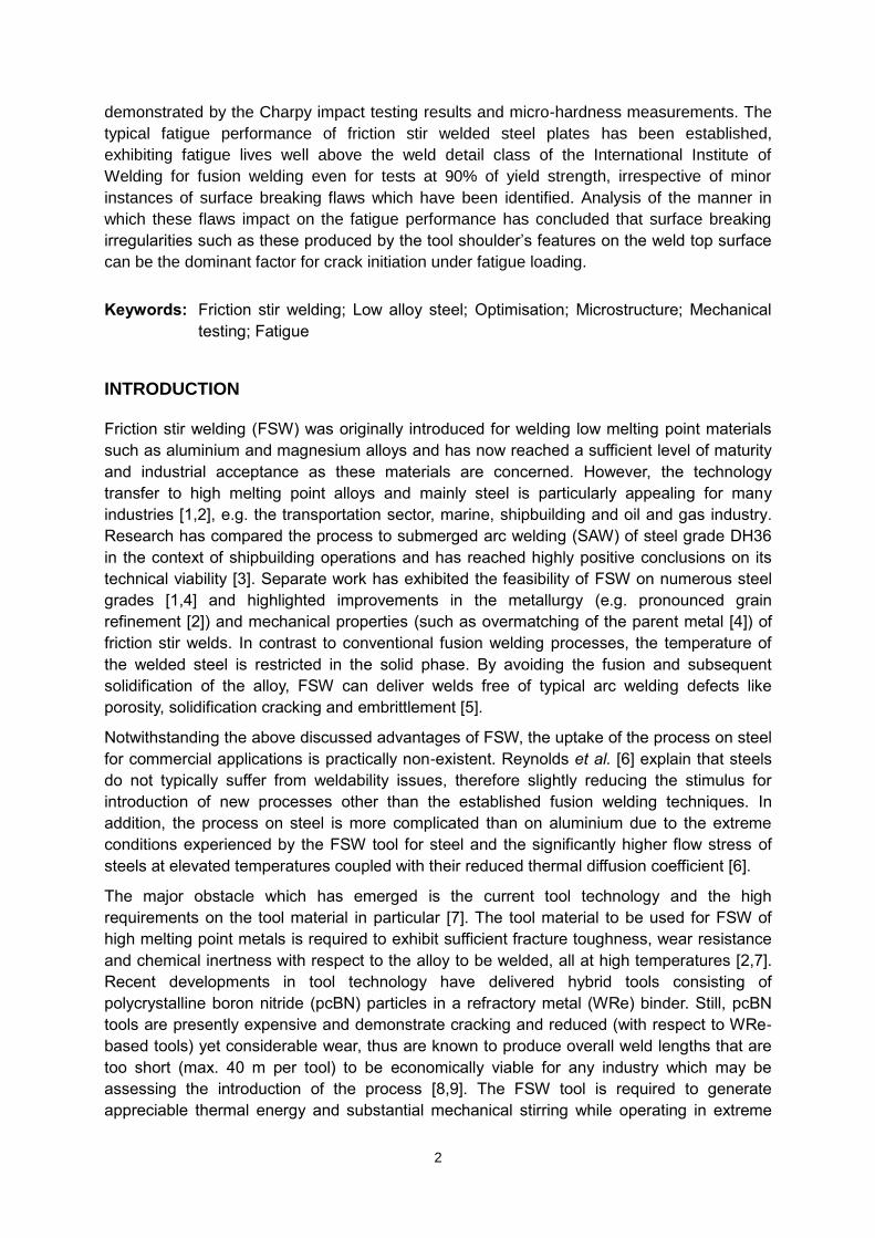
The intermediate traverse speeds (250-400 mm/min) create an acicular bainitic ferrite-rich
microstructure (Fig. 2a) with varying degrees of heterogeneity; the latter is illustrated in Fig.
2b. The relation of enhanced bainite constituent due to higher cooling rates developed by
increasing traverse speed is well identified in Fig. 2a & b, both at 400 rpm rotational speed.
The bainite rich regions reveal evidence of prior austenite grain boundaries (Fig. 2a).
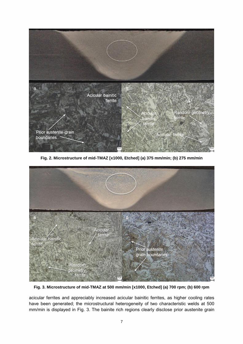
The fast traverse speeds (450-500 mm/min) give rise to heterogeneous microstructures of
7
Fig. 2. Microstructure of mid-TMAZ [x1000, Etched] (a) 375 mm/min; (b) 275 mm/min
Fig. 3. Microstructure of mid-TMAZ at 500 mm/min [x1000, Etched] (a) 700 rpm; (b) 600 rpm
acicular ferrites and appreciably increased acicular bainitic ferrites, as higher cooling rates
have been generated; the microstructural heterogeneity of two characteristic welds at 500
mm/min is displayed in Fig. 3. The bainite rich regions clearly disclose prior austenite grain

8
boundaries (Fig. 3b). Comparable fully acicular microstructure in the TMAZ of friction stir
welded DH36 steel at 450 mm/min is observed in a prior study [4], where it is attributed to the
phase transformation of austenite in high cooling rates.
The employed process parameters have not developed embedded flaws within the TMAZ
which can adversely affect the welds’ quality or mechanical performance, thus establishing
that high speed FSW of steel is achievable at a wide range of traverse speeds. However,
several intermediate and fast weld parameters have generated surface breaking flaws, either
as incomplete fusion paths (also described as laps) on the top surface or minor unwelded
sections of the original butted plate interface (hence flaws) at the weld root; both types have
been thoroughly discussed in prior publications [13,18,20].
Transverse tensile properties
The slow and intermediate friction stir welds exhibit consistent fracture in the parent material
(18 out of the 25 welds) during transverse tensile testing, thereby denoting higher strength
than the DH36 base material, as typically reported in the relevant technical literature [2–4].
The associated tensile property data and the corresponding fracture surface analysis have
been provided in a previous work [13]. The fatigue testing parameters were consistently
computed using an average YS of 382 MPa.
The process is less tolerant to parameter variations at the high welding traverse speeds of
450 mm/min and 500 mm/min, where only one in 7 welds exhibits the above discussed
ductile fracture behaviour. In contrast, most tensile samples fractured in the TMAZ through
the top surface laps on the advancing side, or displayed unstable behaviour (fracture either
inside the weld or the parent material), i.e. no steady state conditions have been attained.
Hardness distribution
The hardness of the weld region, irrespective of position, has been shown to increase with
rising traverse speed [13,18]. This is an expected finding considering that higher traverse
speeds develop higher cooling rates thus harder phases; the increasing bainite content with
faster traverse speeds has been demonstrated in the microstructural characterisation above.
Overall, the welds’ hardness is higher than the base material with peaks either in the central
TMAZ or towards the advancing side. The slow and intermediate welds exhibit moderately
even spread of hardness values across the weld zone and this is reflected in their transverse
tensile testing performance. Class rules for fusion welding require that the maximum
hardness does not exceed 350 HV for steel grades such as DH36 [16]. All slow and
intermediate welds apart from one would be deemed acceptable should they were assessed
by fusion welding rules [16]. High hardness but still within class requirements [16] is recorded
for only one weld of the fast group, i.e. the weld at 700 rpm which performed satisfactorily in
the tensile testing programme.
Impact toughness investigation
Previous work [13] discussed the impact toughness distribution of 6 representative welds,
most of which disclosed impact toughness lower than the parent material and the
intermediate and fast welds demonstrated gradual increase of impact toughness from the
outer TMAZ towards the weld centreline with a peak in the inner advancing side. The study
[13] concluded that the welds’ impact toughness increases with higher traverse speeds, thus
9
supporting the argument for high speed steel FSW, but this favourable effect was identified
solely on the advancing side.
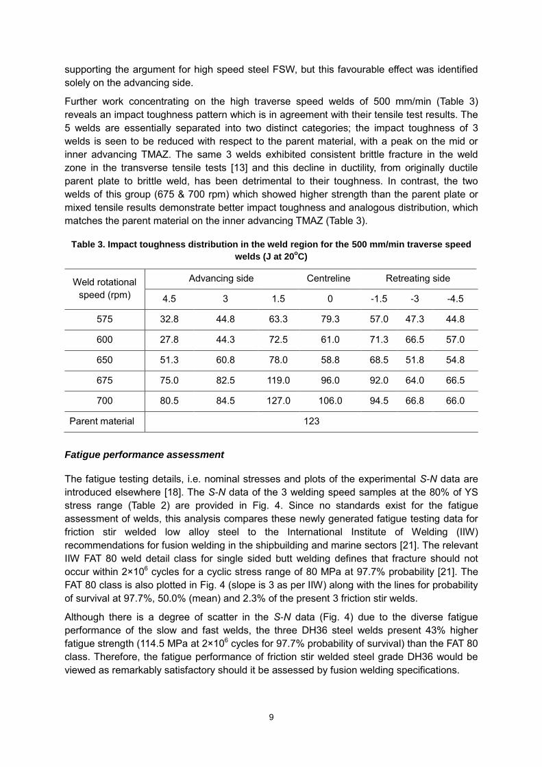
Further work concentrating on the high traverse speed welds of 500 mm/min (Table 3)
reveals an impact toughness pattern which is in agreement with their tensile test results. The
5 welds are essentially separated into two distinct categories; the impact toughness of 3
welds is seen to be reduced with respect to the parent material, with a peak on the mid or
inner advancing TMAZ. The same 3 welds exhibited consistent brittle fracture in the weld
zone in the transverse tensile tests [13] and this decline in ductility, from originally ductile
parent plate to brittle weld, has been detrimental to their toughness. In contrast, the two
welds of this group (675 & 700 rpm) which showed higher strength than the parent plate or
mixed tensile results demonstrate better impact toughness and analogous distribution, which
matches the parent material on the inner advancing TMAZ (Table 3).
Table 3. Impact toughness distribution in the weld region for the 500 mm/min traverse speed
welds (J at 20oC)
Weld rotational
speed (rpm)
Advancing side Centreline Retreating side
4.5 3 1.5 0 -1.5 -3 -4.5
575 32.8 44.8 63.3 79.3 57.0 47.3 44.8
600 27.8 44.3 72.5 61.0 71.3 66.5 57.0
650 51.3 60.8 78.0 58.8 68.5 51.8 54.8
675 75.0 82.5 119.0 96.0 92.0 64.0 66.5
700 80.5 84.5 127.0 106.0 94.5 66.8 66.0
Parent material 123
Fatigue performance assessment
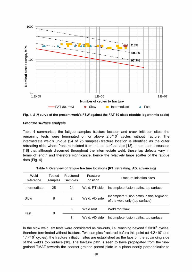
The fatigue testing details, i.e. nominal stresses and plots of the experimental S-N data are
introduced elsewhere [18]. The S-N data of the 3 welding speed samples at the 80% of YS
stress range (Table 2) are provided in Fig. 4. Since no standards exist for the fatigue
assessment of welds, this analysis compares these newly generated fatigue testing data for
friction stir welded low alloy steel to the International Institute of Welding (IIW)
recommendations for fusion welding in the shipbuilding and marine sectors [21]. The relevant
IIW FAT 80 weld detail class for single sided butt welding defines that fracture should not
occur within 2×10⁶ cycles for a cyclic stress range of 80 MPa at 97.7% probability [21]. The
FAT 80 class is also plotted in Fig. 4 (slope is 3 as per IIW) along with the lines for probability
of survival at 97.7%, 50.0% (mean) and 2.3% of the present 3 friction stir welds.
Although there is a degree of scatter in the S-N data (Fig. 4) due to the diverse fatigue
performance of the slow and fast welds, the three DH36 steel welds present 43% higher
fatigue strength (114.5 MPa at 2×10⁶ cycles for 97.7% probability of survival) than the FAT 80
class. Therefore, the fatigue performance of friction stir welded steel grade DH36 would be
viewed as remarkably satisfactory should it be assessed by fusion welding specifications.
10
Fig. 4. S-N curve of the present work’s FSW against the FAT 80 class (double logarithmic scale)
Fracture surface analysis
Table 4 summarises the fatigue samples’ fracture location and crack initiation sites; the
remaining tests were terminated on or above 2.5*106 cycles without fracture. The
intermediate weld’s unique (24 of 25 samples) fracture location is identified as the outer
retreating side, where fracture initiated from the top surface laps [18]. It has been discussed
[18] that although discerned throughout the intermediate weld, these lap defects vary in
terms of length and therefore significance, hence the relatively large scatter of the fatigue
data (Fig. 4).
Table 4. Overview of fatigue fracture locations (RT: retreating; AD: advancing)
Weld
reference
Tested
samples
Fractured
samples
Fracture
position Fracture initiation sites
Intermediate 25 24 Weld, RT side Incomplete fusion paths, top surface
Slow 8 2 Weld, AD side Incomplete fusion paths in this segment
of the weld only (top surface)
Fast 8
5 Weld root Weld root flaw
3 Weld, AD side Incomplete fusion paths, top surface
In the slow weld, six tests were considered as run-outs, i.e. reaching beyond 2.5×10⁶ cycles,
therefore terminated without fracture. Two samples fractured before this point (at 4.2×10⁵ and
1.1×10⁶ cycles); the fracture initiation sites are established as the laps on the advancing side
of the weld’s top surface [18]. The fracture path is seen to have propagated from the fine-
grained TMAZ towards the coarser-grained parent plate in a plane nearly perpendicular to
10
100
1000
1.E+05 1.E+06 1.E+07
No
min
al
str
ess r
an
ge,
MP
a
Number of cycles to fracture
FAT 80, m=3 Slow Intermediate Fast
97.7%
2.3%
50.0%

11
the top surface (Fig. 5); two more pronounced of the laps from which cracks did not
propagate are marked in Fig. 5.
Fig. 5. Macrograph of slow weld sample's fracture path (side view) [Etched]
Fig. 6. Fast weld sample tested at 80% of YS (731,208 cycles to fracture)
The 8 fast weld samples present diverse fracture locations based on the dominant flaw
having developed in each segment of the weld length. The fracture initiation site for 5
samples is seen at the weld root flaw and their fracture surfaces are analogous to the
intermediate and slow fractured samples (Fig. 6). The fracture path has propagated
transversely through the butted plates [18]. Cracks initiated for 3 more samples at the laps
which had been formed on the advancing side of the weld’s top surface and propagated
through rarely seen minor embedded flaws on the same side; the relevant fracture surfaces
have been scrutinised previously [18].
CONCLUSIONS
FSW is seen to deliver substantial merits in welding of steel, but the process requires
suitable optimisation in terms of high speed welding of acceptable quality joints within
application-specific requirements in order to achieve wider industrial acceptance. This work

12
has reported on a comprehensive investigation of steel FSW with a primary focus on marine
and shipbuilding applications through a number of in-depth experimental testing programmes
within the large-scale European research project HILDA. The process parameter
development programme has produced numerous DH36 steel friction stir butt welds by
employing varying tool rotational and traverse speeds up to 500 mm/min, thus concluding
that high speed FSW of steel is feasible and moreover, can deliver significant improvements
in the techno-economic competitiveness of the process relative to fusion welding methods.
Since high traverse speed FSW is expected to affect the weld quality, 25 of the produced
welds have been assessed through microstructural examination and mechanical testing to
confirm any enhancements to the techno-economic competitiveness of the process.
Metallographic examination has established that significant grain refinement of the original
DH36 parent material microstructure is promoted during welding. FSW of steel develops a
complex metallurgical system which is highly dependent on the employed process
parameters, chiefly tool traverse speed. Although the assessed welding parameters have
produced no defects in the main body of the weld zone hence increasing the confidence in
the quality of high speed FSW, a weld root flaw and top surface breaking flaws have been
detected in most welds.
Transverse tensile testing has consistently demonstrated that all slow and intermediate welds
have higher yield strength compared to the parent material, whilst most fast weld samples
fractured in the weld zone suggesting reduced tolerance to parameter variations. The weld
hardness is seen to increase with increasing traverse speed and this is attributed to the
evolution of harder phases in the microstructure, but most examined welds show hardness
distribution within class rules. Improvement in impact toughness with increasing traverse
speed has been recorded and this provides additional weight to the potential of high speed
steel FSW.
Since the fatigue performance of welded components is of paramount importance in marine
applications and due to the lack of pertinent testing specifications, a new fatigue testing
procedure was implemented therefore generating the first S-N curve on friction stir welded
DH36 steel. All examined friction stir welds exhibit excellent fatigue performance, better than
relevant international recommendations for fusion welding. Moreover, investigation of the
relation between weld flaws and fatigue performance has revealed that minor embedded
flaws do not initiate cracks whilst surface breaking flaws, i.e. lack of penetration or the
indentations on the weld top surface by the tool shoulder are recognised as the critical factor
for crack propagation. The welds’ fatigue life is expected to increase dramatically when the
latter is addressed, as the FSW technology continues to improve.
ACKNOWLEDGEMENTS
The authors gratefully acknowledge the financial support of the European Union which has
funded this work as part of the Collaborative Research Project HILDA through the Seventh
Framework Programme (SCP2-GA-2012-314534-HILDA).
REFERENCES
[1] Thomas WM, Threadgill PL, Nicholas ED. Feasibility of friction stir welding steel. Sci Technol Weld Join 1999;4:365–72.

13
[2] Lienert T, Stellwag W, Grimmett B, Warke R. Friction stir welding studies on mild steel. Weld J Res Suppl 2003;82:1–9.
[3] McPherson N, Galloway A, Cater S, Hambling S. Friction stir welding of thin DH36 steel plate. Sci Technol Weld Join 2013;18:441–50.
[4] Reynolds AP, Tang W, Posada M, Deloach J. Friction stir welding of DH36 steel. Sci Technol Weld Join 2003;8:455–60.
[5] Barnes SJ, Bhatti AR, Steuwer A, Johnson R, Altenkirch J, Withers PJ. Friction Stir Welding in HSLA-65 Steel: Part I. Influence of Weld Speed and Tool Material on Microstructural Development. Metall Mater Trans A 2012;43:2342–55.
[6] Reynolds A., Tang W, Gnaupel-Herold T, Prask H. Structure, properties, and residual stress of 304L stainless steel friction stir welds. Scr Mater 2003;48:1289–94.
[7] Wang J, Su J, Mishra RS, Xu R, Baumann JA. Tool wear mechanisms in friction stir welding of Ti–6Al–4V alloy. Wear 2014;321:25–32.
[8] Toumpis A, Galloway A, Cater S, Molter L. A techno-economic evaluation of friction stir welding of DH36 steel. 10th Int. Frict. Stir Weld. Symp., Beijing, China: 2014.
[9] Collaborative Research Project HILDA (High Integrity Low Distortion Assembly), E.U. Seventh Framework Programme (SCP2-GA-2012-314534-HILDA).
[10] Bhadeshia HKDH, DebRoy T. Critical assessment: friction stir welding of steels. Sci Technol Weld Join 2009;14:193–6.
[11] Fraser K, St-Georges L, Kiss L. Optimization of Friction Stir Welding Tool Advance Speed via Monte-Carlo Simulation of the Friction Stir Welding Process. Materials (Basel) 2014;7:3435–52.
[12] Ghosh M, Kumar K, Mishra RS. Process Optimization for Friction-Stir-Welded Martensitic Steel. Metall Mater Trans A 2012;43:1966–75.
[13] Toumpis A, Galloway A, Cater S, McPherson N. Development of a process envelope for friction stir welding of DH36 steel – A step change. Mater Des 2014;62:64–75.
[14] British Standards Institution. BS EN ISO 6892-1. Metallic materials – Tensile testing – Part 1: Method of test at room temperature. London: 2009.
[15] British Standards Institution. BS EN ISO 148-1. Metallic materials – Charpy pendulum impact test – Part 1: Test method. London: 2010.
[16] Lloyd’s Register. Rules for the Manufacture, Testing and Certification of Materials. London: 2014.
[17] British Standards Institution. BS 7270. Metallic materials – Constant amplitude strain controlled axial fatigue – Method of test. London: 2006.
[18] Toumpis A, Galloway A, Molter L, Polezhayeva H. Systematic investigation of the fatigue performance of a friction stir welded low alloy steel. Mater Des 2015;80:116–28.
[19] Cho H-H, Kang SH, Kim S-H, Oh KH, Kim HJ, Chang W-S, et al. Microstructural evolution in friction stir welding of high-strength linepipe steel. Mater Des 2012;34:258–67.
[20] Stevenson R, Toumpis A, Galloway A. Defect tolerance of friction stir welds in DH36 steel. Mater Des 2015;87:701–11.
[21] Hobbacher A. Recommendations for Fatigue Design of Welded Joints and Components. International Institute of Welding, doc. IIW-1823-07. Paris: 2008.