Embed Size (px)
Citation preview

LCP Distal Humerus Plates
The anatomic fixation system for the distal humerus with angular stability
Surgical technique
LockingCompressionPlate
LCP

Synthes 1
Contents
WarningThis description is not sufficient for immediate application of the instrumentation. Instruction by a surgeon experienced inhandling this instrumentation is highly recommended.
LCP Distal Humerus Plates
Indications and contraindications 2
Implants 3
Instruments 5
Preparation 6
Dorsolateral plate with support 9
Medial Plate 14
Fixing the shaft 16
Option: Dorsolateral plate without support 17
Option: Positioning and compression device PCD 19
Implant removal 24

2
Indications and contraindications
LCP Distal Humerus Plates
Indications
– Intraarticular fractures of the distal humerus– Supracondylar fractures of the distal humerus – Non-unions of the distal humerus
Contraindications
– Acute infections– Children in the growth phase

Synthes 3
Implants
Distal humerus plates
Distal Humerus Plate, dorsolateral, right
Art. No. Holes
X41.262 3
X41.264 5
X41.266 7
X41.268 9
X41.300 14
Distal Humerus Plate, dorsolateral, left
Art. No. Holes
X41.263 3
X41.265 5
X41.267 7
X41.269 9
X41.301 14
Distal Humerus Plate, dorsolateral with support, right
Art. No. Holes
X41.272 3
X41.274 5
X41.276 7
X41.278 9
X41.302 14
Distal Humerus Plate, dorsolateral with support, left
Art. No. Holes
X41.273 3
X41.275 5
X41.277 7
X41.279 9
X41.303 14
Distal Humerus Plate, medial, right
Art. No. Holes
X41.282 3
X41.284 5
X41.286 7
X41.288 9
X41.304 14
Distal Humerus Plate, medial, left
Art. No. Holes
X41.283 3
X41.285 5
X41.287 7
X41.289 9
X41.305 14
LCP Distal Humerus Plates

4
Implants
LCP Distal Humerus Plates
LCP locking screws
X02.214–260 LCP Locking Screw � 2.7 mm (head LCP 2,4), length 14–60 mm, self-tapping, with Stardrive® recess
X12.102–124 LCP Locking Screw � 3.5 mm, length 12–60 mm, self-tapping, with Stardrive® recess
X13.012–060 LCP Locking Screw � 3.5 mm, length 12–60 mm, self-tapping with hexagonal recess
Standard screws
X01.764–790 Cortex Screw � 2.4 mm, length 14–40 mm, self-tapping with Stardrive® recess
X04.814–860 Cortex Screw � 3.5 mm, length 14–60 mm, self-tapping, with hexagonal recess

Instruments
LCP Distal Humerus Plates
Torque Limiters
511.776 Torque Limiter 0.8 Nm, for LCP locking screws � 2.4/2.7 mm with AO/ASIF quick coupling for power tool/handle
511.773 Torque Limiter 1.5 Nm, for LCP locking screws � 3.5 mm with AO/ASIF quick coupling for power tool/handle
511.770 Torque Limiter 1.5 Nm, for LCP locking screws � 3.5 mmwith CAD coupling for power tool/handle
Important: always use TLA when inserting LCP screws, otherwise plate and/or screws might be damaged
Drilling instruments for LCP locking screws � 2.7 mm
323.061 LCP Drill Sleeve 2.7 (head LCP2.4), with scale up to 60 mm
323.062 Drill Bit � 2.0 mm, with double markings, L 140/115
313.351– Positioning and Compression Device (PCD) for the 313.357 dorso-lateral plate with support, with length markings
Note: The PCD can also be used without plate to implement 3.5mm cortex screws.
Length measurement devices
319.005 Depth Gauge for Screws � 2.0 and 2.4 mm, measuring range up to 40 mm
319.010 Depth Gauge for Screws � 2.7 to 4.0 mm, measuring range up to 60 mm
Synthes 5

6
Preparation
LCP Distal Humerus Plates
Note: Experience in the use of the Locking Compression PlateSystem LCP (see surgical technique 036.000.019) or instructionby a surgeon with corresponding experience is recommended.
1Position patient
The lateral decubitus position is usually chosen. In severe C3fractures, the fully prone position can be used, if the patient isotherwise fit. The arm is rested on a padded bar allowingelbow flexion of 120°. In rare cases bone graft may be neededand it is wise to prepare a donor site. The use of a tourniquet,preferably sterile, is not essential, but can make it easier toidentify the ulnar nerve.
2Surgical approach
All fractures are approached through a slightly curvedposterior incision just radial to the olecranon. The ulnar nerveis gently identified and may need to be isolated and elevatedat the ulnar epicondyle.
For supracondylar fractures or simple articular fractures it maybe sufficient to expose the nerves on both sides of the triceps.For comminuted fractures a distally pointed chevron olecranonosteotomy exposes the fracture best.
When using longer plates the radial nerve has to be carefullyidentified.
Synthes 7
3Reduce fracture and fix temporarily
For C-type fractures, reduce the articular fragments of thedistal block under direct vision or image intensifier and fix themtemporarily, using Kirschner wires and/or pointed reductionforceps.
Fix the distal block temporarily to the shaft using K-wires inboth columns and/or forceps and make sure that the anatomyof the distal humerus is restored.
Note: LCP locking screws are not suitable for reduction, sincethey cannot effect compression.The fracture must therefore bereduced before inserting locking screws.
When using longer plates the radial nerve has to be carefullyidentified.
4Choose dorsolateral plate (with or without support)
For the dorsolateral side, choose the type of implant to beused. The dorsolateral plates allow for screw insertion in aposterior-anterior direction. The plate with support allows foradditional screw insertion through the lateral epicondyle in alateral-medial direction.
Note: On very small humeri the support may protrudeextensively over the lateral epicondyle, in which case the useof a plate without support is recommended.
8
LCP Distal Humerus PlatesPreparation
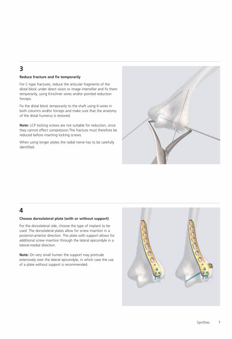
5Determine the length of the plates
Choose plate lengths that offer sufficient fixation proximal tothe fracture lines. To prevent extensive diaphyseal stress, themedial and dorsolateral plates may not have the same length.
Sample: medial 5 holes, dorsolateral 7 holes.
Important: To reach sufficient stability for early mobilizationboth plates dorsolateral and medial have to be used in case ofsevere fractures. Application of single plates should be limitedto simple fractures where one column is still intact.
Important: For fractures extending into the shaft always useboth dorsolateral and medial plates to have sufficient strength,especially when using 9 or 14 hole plates.
6Prepare plates, bending
Required instruments
Bending Pliers for Plates 2.4 to 4.0, length 230 mm 329.150
Bending Iron for Plates 2.4 to 3.5, length 145 mm 329.040/329.050
LCP Drill Sleeve 2,7 (head LCP 2,4), with scale up to 60 mm 323.061
The form of the distal humerus can vary between individuals.Bending might be required to adapt the plate form. Usebending pliers and irons to shape the plates.
Be careful to observe the LCP locking screw direction of thedistal screws during the bending. Use drill guide to check.
Note: If only cortex screws are used, the plates need to becongruent with the surface of the bone and bending ortorquing may be required. Normally only minimal bending isnecessary when using LCP locking screws.
Synthes 9
Dorsolateral plate with support
LCP Distal Humerus Plates
Position and fix the dorsolateral plate with support
Normally a transolecranon approach is used and the platefixation starts on the dorsolateral side of the distal humerus.
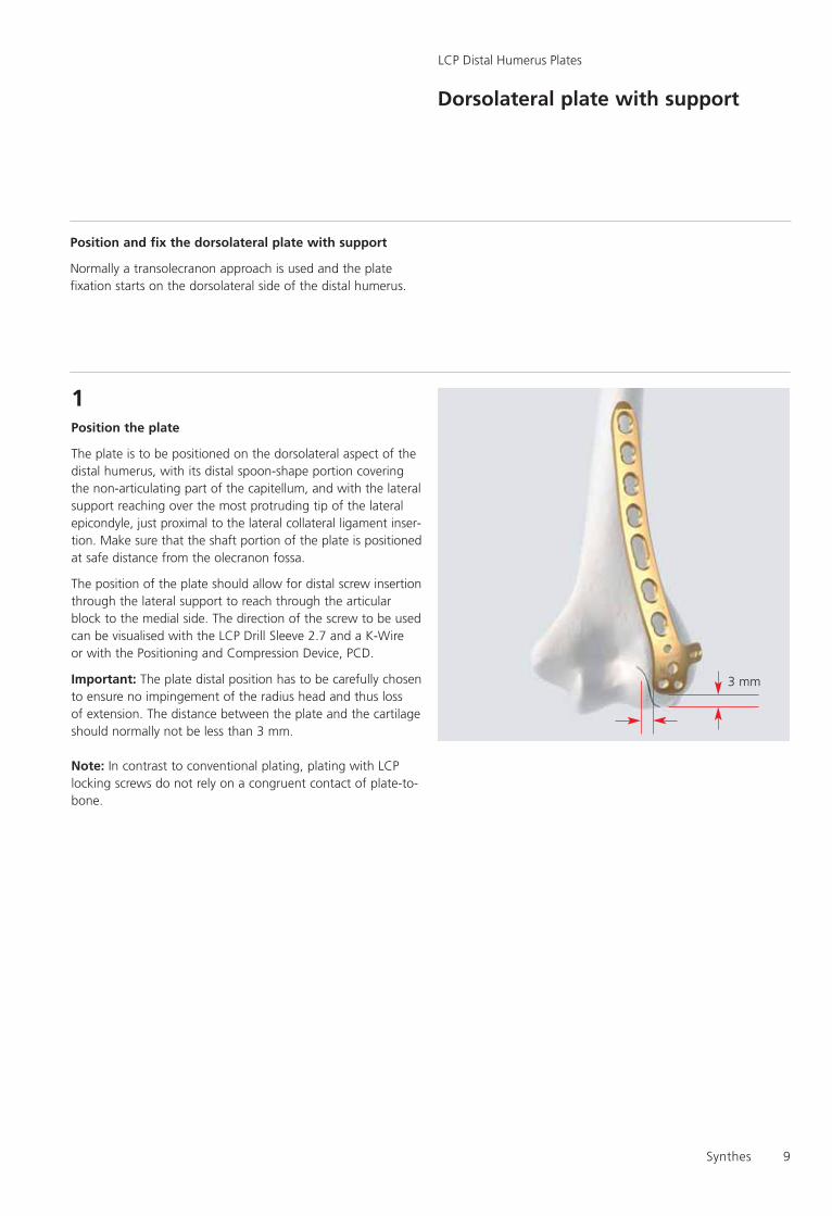
1Position the plate
The plate is to be positioned on the dorsolateral aspect of thedistal humerus, with its distal spoon-shape portion coveringthe non-articulating part of the capitellum, and with the lateralsupport reaching over the most protruding tip of the lateralepicondyle, just proximal to the lateral collateral ligament inser-tion. Make sure that the shaft portion of the plate is positionedat safe distance from the olecranon fossa.
The position of the plate should allow for distal screw insertionthrough the lateral support to reach through the articularblock to the medial side. The direction of the screw to be usedcan be visualised with the LCP Drill Sleeve 2.7 and a K-Wire or with the Positioning and Compression Device, PCD.
Important: The plate distal position has to be carefully chosento ensure no impingement of the radius head and thus loss of extension. The distance between the plate and the cartilageshould normally not be less than 3 mm.
Note: In contrast to conventional plating, plating with LCPlocking screws do not rely on a congruent contact of plate-to-bone.
3 mm
10
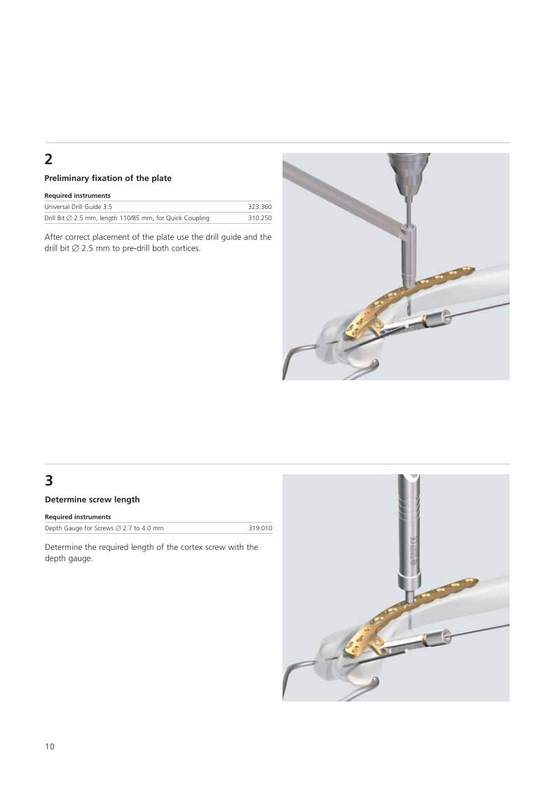
3Determine screw length
Required instruments
Depth Gauge for Screws � 2.7 to 4.0 mm 319.010
Determine the required length of the cortex screw with thedepth gauge.
2Preliminary fixation of the plate
Required instruments
Universal Drill Guide 3.5 323.360
Drill Bit � 2.5 mm, length 110/85 mm, for Quick Coupling 310.250
After correct placement of the plate use the drill guide and thedrill bit � 2.5 mm to pre-drill both cortices.
Synthes 11
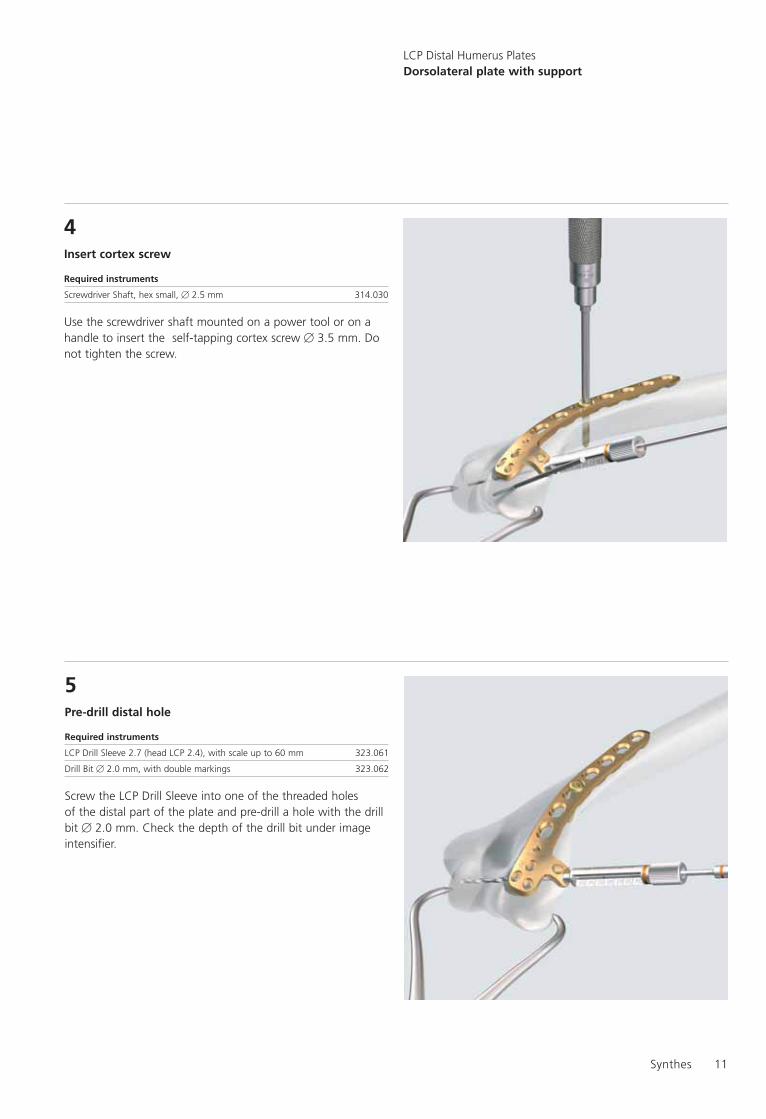
5Pre-drill distal hole
Required instruments
LCP Drill Sleeve 2.7 (head LCP 2.4), with scale up to 60 mm 323.061
Drill Bit � 2.0 mm, with double markings 323.062
Screw the LCP Drill Sleeve into one of the threaded holes of the distal part of the plate and pre-drill a hole with the drillbit � 2.0 mm. Check the depth of the drill bit under imageintensifier.
4Insert cortex screw
Required instruments
Screwdriver Shaft, hex small, � 2.5 mm 314.030
Use the screwdriver shaft mounted on a power tool or on ahandle to insert the self-tapping cortex screw � 3.5 mm. Donot tighten the screw.
LCP Distal Humerus PlatesDorsolateral plate with support

12
6Determine length of screw
Required instruments
LCP Drill Sleeve 2.7 (head LCP 2.4), with Scale up to 60 mm,for Drill Bits � 2.0 mm 323.061
Drill Bit � 2.0 mm, with double marking, length 140/115 mm, 3-flute, for Quick Coupling 323.062
Depth Gauge for Screws � 2.0 and 2.4 mm, measuring range up to 40 mm 319.005
Depth Gauge for Screws � 2.7 to 4.0 mm, measuring rangeup to 60 mm 319.010
Determine the required length of the screw by using the scaleon the drill guide. If a single marking is visible on the drill bit,the scale from 0–30 mm applies; if a double marking is visible,the scale from 30–60 mm applies.
Option: Use a Depth Gauge 319.005 to check length.
Note: For all screw types: using the exact length indication will lead to a screw which ends exactly at the exit point of the bone for all measuring devices contained in the set. Thus forbicortical screws (shaft), the chosen screw must be a littlelonger than the indication. Screws in the joint must be a littleshorter.
If Depth Gauge 319.010 is used for 2.7 mm screws, subtract 4 mm from the indication to obtain a correctly comparablescrew length.

Synthes 13
7Insert distal screws LCP 2,7 mm
Required instruments
Holding Sleeve for LCP Screw Stardrive � 2.4/2.7 mm 313.301
Screwdriver Shaft Stardrive, T8, cylindrical, with groove 313.304
Torque Limiter, 0.8 Nm, with AO/ASIF Quick Coupling 511.776
The LCP locking screw can be inserted manually or by powertool.
Use the screwdriver shaft, attached to the torque limiter. Use the holding sleeve if necessary.
A “click” indicates that the screw is locked into the plate.
Important: always use TLA when inserting LCP lockingscrews, otherwise plate and/or screws might be damaged
Option: Use cortex screw � 2.4 mm
Repeat the above steps for all distal holes to be used.
Important: It is recommended to use minimum one screw onthe lateral side which crosses the distal block. Screw lengthshould be 40–60mm depending on the size of the humerus.
The recommended screw length for the capitellum is 16–24 mm.
Important: When inserting the screws into the capitellum, becareful not to damage the joint due to the length of thescrews. It is recommended to check the position of the screwswith the image intensifier during movement of the elbow.
LCP Distal Humerus PlatesDorsolateral plate with support
14
Medial Plate
LCP Distal Humerus Plates
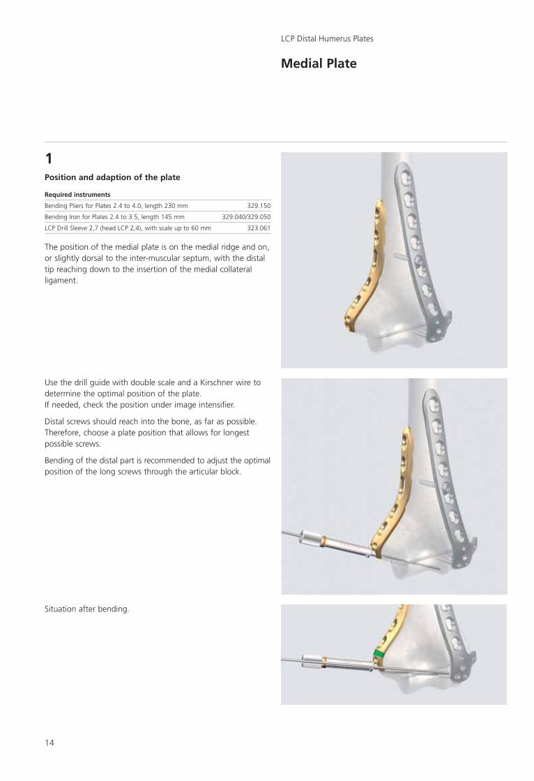
1Position and adaption of the plate
Required instruments
Bending Pliers for Plates 2.4 to 4.0, length 230 mm 329.150
Bending Iron for Plates 2.4 to 3.5, length 145 mm 329.040/329.050
LCP Drill Sleeve 2,7 (head LCP 2,4), with scale up to 60 mm 323.061
The position of the medial plate is on the medial ridge and on,or slightly dorsal to the inter-muscular septum, with the distaltip reaching down to the insertion of the medial collateralligament.
Use the drill guide with double scale and a Kirschner wire todetermine the optimal position of the plate.If needed, check the position under image intensifier.
Distal screws should reach into the bone, as far as possible.Therefore, choose a plate position that allows for longestpossible screws.
Bending of the distal part is recommended to adjust the optimalposition of the long screws through the articular block.
Situation after bending.

Synthes 15
2Preliminary fixation of the plate to the bone
Required instruments
Drill Bit Ø 2,5 mm, length 110/85 mm, for Quick Coupling 310.250
Universal Drill Guide 3.5 (2.5/3.5) 323.360
LCP Drill Sleeve 2.7 (head LCP 2.4), with scale up to 60 mm 323.061
Use a K-wire through the drill sleeve in the distal hole to fix the distal plate position. Make sure no collision with thealready implemented screws occurs.
Use the drill guide and the drill bit � 2.5 mm to pre-drill bothcortices. Insert a 3.5 mm cortex screw through the long holeof the plate.
3Fix the distal part of the plate to the bone
Use a similar procedure as for the dorsolateral plate to insertthe LCP locking or cortex screws (see dorsolateral plate withsupport).
Important: Careful drilling is necessary as collision with thescrews of the dorsolateral plate may occur. In case of collisionstop drilling and use adequate screw for fixation. Use otheravailable holes for application of more screws.
Important: It is recommended to use minimum one screw onthe medial side and one screw on the lateral side which crossthe distal block. Screw length should be 40–60mm dependingon the size of the humerus.
16
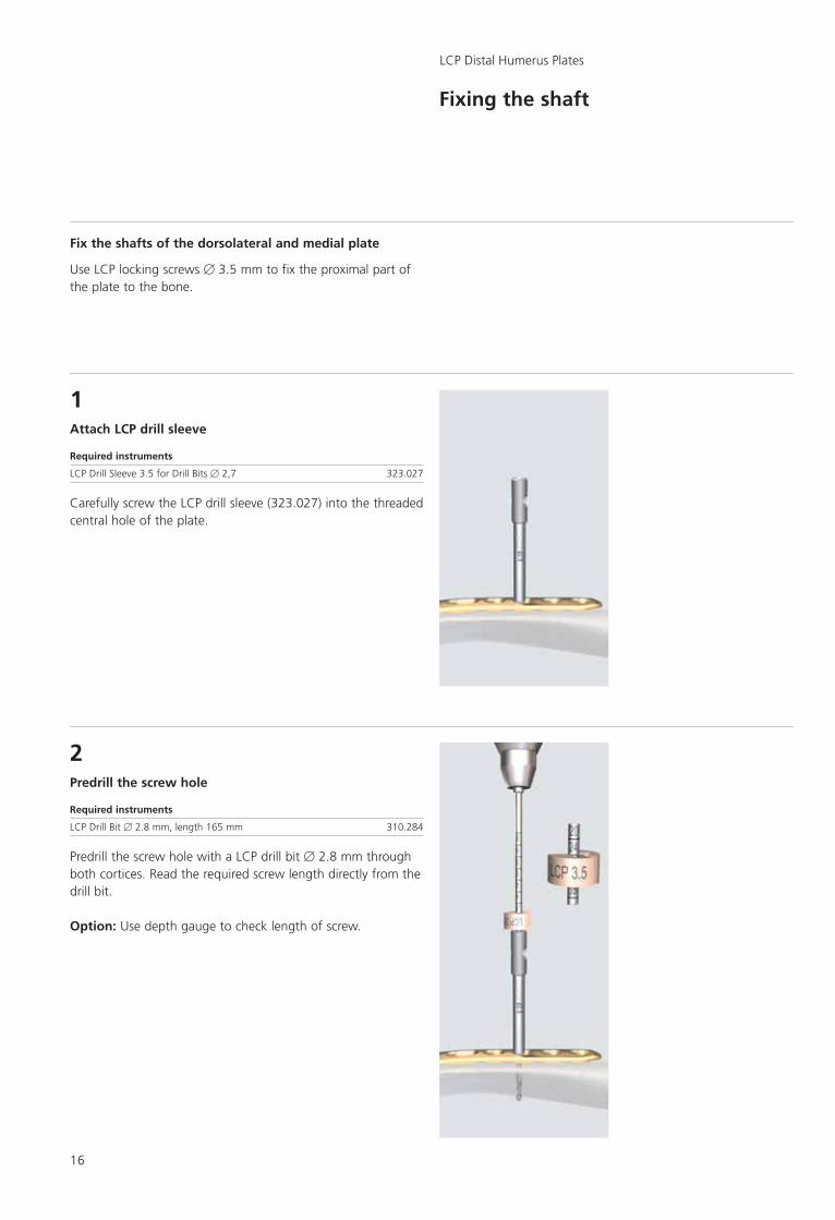
1Attach LCP drill sleeve
Required instruments
LCP Drill Sleeve 3.5 for Drill Bits � 2,7 323.027
Carefully screw the LCP drill sleeve (323.027) into the threadedcentral hole of the plate.
2Predrill the screw hole
Required instruments
LCP Drill Bit � 2.8 mm, length 165 mm 310.284
Predrill the screw hole with a LCP drill bit � 2.8 mm throughboth cortices. Read the required screw length directly from thedrill bit.
Option: Use depth gauge to check length of screw.
Fixing the shaft
LCP Distal Humerus Plates
Fix the shafts of the dorsolateral and medial plate
Use LCP locking screws � 3.5 mm to fix the proximal part ofthe plate to the bone.
Synthes 17
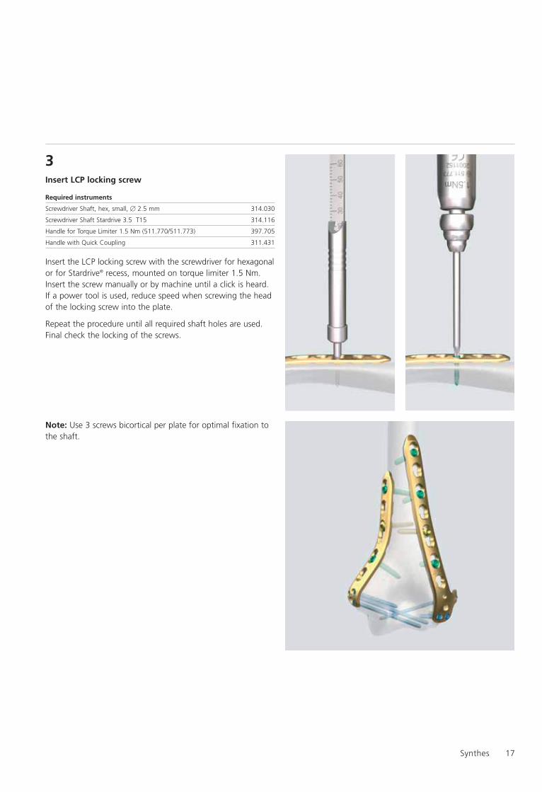
3Insert LCP locking screw
Required instruments
Screwdriver Shaft, hex, small, � 2.5 mm 314.030
Screwdriver Shaft Stardrive 3.5 T15 314.116
Handle for Torque Limiter 1.5 Nm (511.770/511.773) 397.705
Handle with Quick Coupling 311.431
Insert the LCP locking screw with the screwdriver for hexagonalor for Stardrive® recess, mounted on torque limiter 1.5 Nm.Insert the screw manually or by machine until a click is heard.If a power tool is used, reduce speed when screwing the headof the locking screw into the plate.
Repeat the procedure until all required shaft holes are used.Final check the locking of the screws.
Note: Use 3 screws bicortical per plate for optimal fixation tothe shaft.
18
Option: Dorsolateral plate without support
LCP Distal Humerus Plates
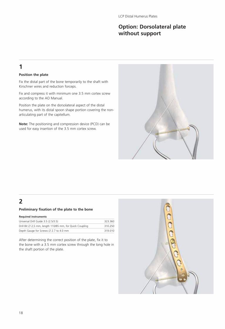
1Position the plate
Fix the distal part of the bone temporarily to the shaft withKirschner wires and reduction forceps.
Fix and compress it with minimum one 3.5 mm cortex screwaccording to the AO Manual.
Position the plate on the dorsolateral aspect of the distalhumerus, with its distal spoon shape portion covering the non-articulating part of the capitellum.
Note: The positioning and compression device (PCD) can beused for easy insertion of the 3.5 mm cortex screw.
2Preliminary fixation of the plate to the bone
Required instruments
Universal Drill Guide 3.5 (2.5/3.5) 323.360
Drill Bit � 2,5 mm, length 110/85 mm, for Quick Coupling 310.250
Depth Gauge for Screws � 2.7 to 4.0 mm 319.010
After determining the correct position of the plate, fix it to the bone with a 3.5 mm cortex screw through the long hole inthe shaft portion of the plate.
Synthes 19
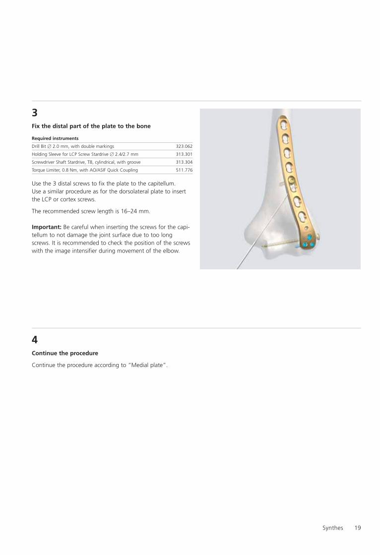
3Fix the distal part of the plate to the bone
Required instruments
Drill Bit � 2.0 mm, with double markings 323.062
Holding Sleeve for LCP Screw Stardrive � 2.4/2.7 mm 313.301
Screwdriver Shaft Stardrive, T8, cylindrical, with groove 313.304
Torque Limiter, 0.8 Nm, with AO/ASIF Quick Coupling 511.776
Use the 3 distal screws to fix the plate to the capitellum. Use a similar procedure as for the dorsolateral plate to insertthe LCP or cortex screws.
The recommended screw length is 16–24 mm.
Important: Be careful when inserting the screws for the capi-tellum to not damage the joint surface due to too long screws. It is recommended to check the position of the screwswith the image intensifier during movement of the elbow.
4Continue the procedure
Continue the procedure according to “Medial plate”.
20
Option: Positioning and compression device PCD
LCP Distal Humerus Plates
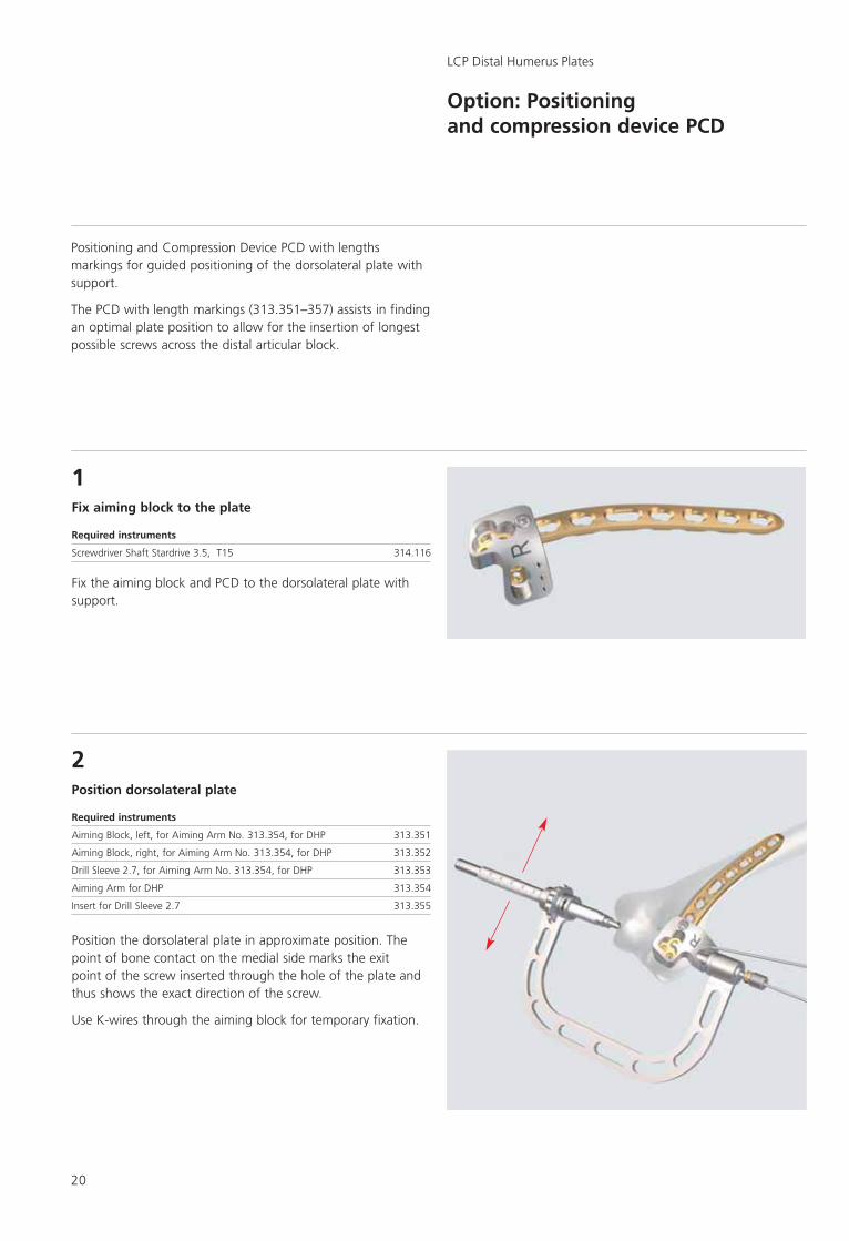
1Fix aiming block to the plate
Required instruments
Screwdriver Shaft Stardrive 3.5, T15 314.116
Fix the aiming block and PCD to the dorsolateral plate withsupport.
2Position dorsolateral plate
Required instruments
Aiming Block, left, for Aiming Arm No. 313.354, for DHP 313.351
Aiming Block, right, for Aiming Arm No. 313.354, for DHP 313.352
Drill Sleeve 2.7, for Aiming Arm No. 313.354, for DHP 313.353
Aiming Arm for DHP 313.354
Insert for Drill Sleeve 2.7 313.355
Position the dorsolateral plate in approximate position. Thepoint of bone contact on the medial side marks the exit point of the screw inserted through the hole of the plate andthus shows the exact direction of the screw.
Use K-wires through the aiming block for temporary fixation.
Positioning and Compression Device PCD with lengthsmarkings for guided positioning of the dorsolateral plate withsupport.
The PCD with length markings (313.351–357) assists in findingan optimal plate position to allow for the insertion of longestpossible screws across the distal articular block.

Synthes 21
3Fix the plate with cortex screw
Required instruments
Universal Drill Guide 3.5 323.360
Drill Bit � 2,5 mm, length 110/85 mm, for Quick Coupling 310.250
Screwdriver Shaft, hex, small, � 2.5 mm 314.030
Use a 3.5 mm cortex screw for preliminary fixation of the plateto the bone.
4Use the PCD to choose the screw length
Read the screw length on the scale of the PCD and choose the required length.
Account a safety margin to the articulating surface (2–10 mm depending on position).

22
5Insert the LCP 2.7 mm screw
Required instruments
Drill Bit � 2.0 mm, with double markings 323.062
Screwdriver Shaft Stardrive, T8, cylindrical, with groove 313.304
Torque Limiter, 0.8 Nm, with AO/ASIF Quick Coupling 511.776
Drill the hole with the drill bit � 2.0 mm. The drill will exit thebone at the medial point of contact of the PCD.
Use a K-wire instead of the drill bit if you need to checkcorrect position of the plate and screw first.
Take out the drill sleeve and insert the LCP 2.7 mm screw with 2.4 head through the PCD.
Synthes 23
LCP Distal Humerus PlatesOption: Positioning and compression device PCD
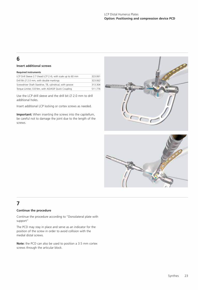
6Insert additional screws
Required instruments
LCP Drill Sleeve 2.7 (head LCP 2.4), with scale up to 60 mm 323.061
Drill Bit � 2.0 mm, with double markings 323.062
Screwdriver Shaft Stardrive, T8, cylindrical, with groove 313.304
Torque Limiter, 0.8 Nm, with AO/ASIF Quick Coupling 511.776
Use the LCP drill sleeve and the drill bit � 2.0 mm to drilladditional holes.
Insert additional LCP locking or cortex screws as needed.
Important: When inserting the screws into the capitellum, be careful not to damage the joint due to the length of thescrews.
7Continue the procedure
Continue the procedure according to “Dorsolateral plate withsupport”
The PCD may stay in place and serve as an indicator for theposition of the screw in order to avoid collision with themedial distal screws.
Note: the PCD can also be used to position a 3.5 mm cortexscrews through the articular block.

24
Implant removal
LCP Distal Humerus Plates
Implant removal
Required instruments
Screwdriver Shaft, hex, small, � 2.5 mm 314.030
Screwdriver Shaft Stardrive 3.5, T15 314.116
Extraction Screw for Screws � 3.5 mm 309.521
Extraction Screw for Screws � 1.5 mm and 2.0 mm 309.510
To remove the implants, unlock all LCP locking screws beforeremoving them completely. The plate may otherwise rotatewhile the last screw is being removed, which can damage thesoft tissue.
If the LCP locking screws cannot be removed with the screwdriver (e.g. the recess of the screw is damaged or the lockingscrew is stuck in the plate), use an Extraction Screw with left-handed thread. Loosen the screw by turning the handlecounter-clockwise.
Important: It is very important to have the correct instrumen-tation available to ensure trouble free implant removal.
The correct screw drivers (hex or Stardrive®) and the extractionscrews are of special importance. Be aware that all LCP lockingscrews in the DHP set are equipped with Stardrive® recess.

0123Presented by: