Embed Size (px)
Citation preview

VA-LCP Distal Humerus Plates 2.7/3.5.The low-profile fixation system with variable angle locking technology.
Technique Guide

Image intensifier control
WarningThis description alone does not provide sufficient background for direct use ofthe instrument set. Instruction by a surgeon experienced in handling theseinstruments is highly recommended.
Reprocessing, Care and Maintenance of Synthes InstrumentsFor general guidelines, function control and dismantling of multi-part instruments,please contact your local sales representative or refer to:www.synthes.com/reprocessing

VA-LCP Distal Humerus Plates 2.7/3.5 Technique Guide Synthes 1
Table of Contents
Introduction
Surgical Technique
Product Information
Bibliography
VA-LCP Distal Humerus Plates 2.7/3.5 2
AO Principles 4
Indications 5
Preparation and Approach 6
Determination of Fixation Technique 10
Insert Lateral-Column Plate 14
Insert Distal Screws in Lateral-Column Plate 20
Insert Medial-Column Plate 25
Insert Distal Screws in Medial-Column Plate 28
Insert Plate-Shaft Screws 29
Fixation of Olecranon Osteotomy 32
Implant Removal 33
Implants 34
Instruments 39
Sets 42
43

Variable angle lockingVariable angle locking screws 2.7 mm give the surgeon theability to create a fixed-angle construct with the freedom of+/-15° off-axis screw angulation.
Plate configurationsThe VA-LCP Elbow Plating System offers three main double-plating configurations for the distal humerus: perpendicular,perpendicular with support, and parallel.
Plate designOptimized metaphyseal plate profile, together with roundededges and an improved anatomical plate fit minimize theprominence of the construct without compromising stability.
Cross-section of the VA-LCP Distal Humerus Plate, medial (1) and the LCP DistalHumerus Plate, medial (2) at the level of the medial epicondyle.
VA-LCP Distal Humerus Plates 2.7/3.5.The low-profile fixation system with variable angle locking technology.
2 Synthes VA-LCP Distal Humerus Plates 2.7/3.5 Technique Guide
1
2

VA-LCP Distal Humerus Plates 2.7/3.5 Technique Guide Synthes 3
1 Medial PlateThe standard medial column plate.
2 Medial Plate, with extensionThe extension buttresses the medial epicondyle and includes an ascending screw that stabilizes the medial column.
VA-LCP Distal Humerus PlatesThe plates offer multiple screw configurations forthe medial and lateral columns, and the articularblock.
3 Lateral PlateThe lateral plate for the parallel-plating configuration.
4 Dorsolateral PlateThe dorsolateral plate for the perpendicular-plating configuration with screws targeting the capitellum.
5 Dorsolateral Plate, with lateral supportThe screws from the lateral support target the articularblock.
12
3
5 4

AO Principles
In 1958, the AO formulated four basic principles, which havebecome the guidelines for internal fixation.1,2 Those princi-ples, as applied to the VA-LCP Elbow System are:
Anatomic reductionPrecontoured plates assist in anatomic reduction.
Stable fixationVariable angle locking screws create a fixed-angle constructproviding angular stability.
Preservation of blood supplyPlates designed with limited plate-to-bone contact helps topreserve the periosteal blood supply. Optimized plate profilesreduce the risk of implant-related soft tissue irritation.
Early, active mobilizationLocking screws create a fixed-angle construct providing angular stability to maintain the anatomical reduction, espe-cially in osteoporotic bone.3
1 Müller ME, M Allgöwer, R Schneider, H Willenegger. Manual of Internal Fixation.3rd ed. Berlin Heidelberg New York: Springer. 1991.
2 Rüedi TP, RE Buckley, CG Moran. AO Principles of Fracture Management. 2nd ed.Stuttgart, New York: Thieme. 2007.
3 Schuster I, J Korner, M Arzdorf, K Schwieger, G Diederichs, B Linke. MechanicalComparison in Cadaver Specimens of Three Different 90-Degree Double-PlateOsteosyntheses for Simulated C2-Type Distal Humerus Fractures with VaryingBone Densities. J Orthop Trauma 2008, 22:113 –120.
4 Synthes VA-LCP Distal Humerus Plates 2.7/3.5 Technique Guide

Indications
– Intra-articular fractures of the distal humerus– Supracondylar fractures of the distal humerus– Nonunions of the distal humerus– Osteotomies of the distal humerus
(e.g. due to malunions, deformities)
VA-LCP Distal Humerus Plates 2.7/3.5 Technique Guide Synthes 5

1Preoperative planning
Complete the preoperative radiographic assessment and prepare the preoperative plan. Use the x-ray templates forthe VA-LCP Distal Humerus Plates (Art. No. 034.000.721,034.000.722 and 034.000.723) to determine the plate type,length, and the position of the screws.
6 Synthes VA-LCP Distal Humerus Plates 2.7/3.5 Technique Guide
Preparation and Approach

2Position patient
Position the patient in prone or in lateral decubitus with thearm on a radiolucent support, or a padded post. The forearmshould be positioned such that it can be flexed to an anglegreater than 120 degrees.
Note: Please consult www.aosurgery.org for further infor -mation.
VA-LCP Distal Humerus Plates 2.7/3.5 Technique Guide Synthes 7

3Approach
Fractures are approached through a slightly curved posteriorincision just radial to the olecranon.
Important:– Identify the ulnar nerve and elevate it at the ulnar epi-
condyle if necessary.– When using longer plates, ensure that the radial nerve is
carefully identified.
The type of approach is determined by the character of thefracture, and the preference and experience of the surgeon.For comminuted fractures, a distally pointed chevron ole -cranon osteotomy exposes the fracture best.
Note: Please consult www.aosurgery.org for further infor -mation.
Preparation and Approach
8 Synthes VA-LCP Distal Humerus Plates 2.7/3.5 Technique Guide

4Reduce fracture and provide temporary fixation
Instrument
03.118.001 Periarticular Reduction Forceps, with pointed ball tips � 6.5 mm, small
For AO C-type fractures, first reduce the fragments of the articular block under image intensifier control and useKirschner wires and/or reduction forceps for temporary fixation.
Fix the articular block to the shaft using Kirschner wiresand/or reduction forceps in both columns to ensure that theanatomy of the distal humerus is restored.
Ensure that the Kirschner wires or reduction forceps will notinterfere with subsequent plate placement.
Notes: – If necessary, reduce the articular block using independent
screws.– When using the dorsolateral plate without lateral support,
it is important to reduce and fix the articular block withscrews according to the AO Principles of Fracture Man-agement (lag screw for simple articular fracture or posi-tion screw for comminuted fracture). Please consultwww.aosurgery.org for further information.
VA-LCP Distal Humerus Plates 2.7/3.5 Technique Guide Synthes 9

10 Synthes VA-LCP Distal Humerus Plates 2.7/3.5 Technique Guide
Determination of Fixation Technique
Select a plate type and length appropriate for the fracture.
Notes:– Choose the plate lengths that offer sufficient fixation
proximal to the fracture line.– To achieve sufficient stability for early mobilization in
AO A-type and C-type fractures, use two plates: one forthe medial and one for the lateral column.
1Determine lateral-column plate type and length
Instruments
03.117.004 Trial Implants for VA-LCP Distal Humeral or Plate 2.7/3.5, dorsolateral, 03.117.104 with lateral support, right or left, 4 holes
03.117.802 Trial Implants for VA-LCP Distal Humeral or Plate 2.7 / 3.5, lateral, right or left, 2 holes03.117.902
Notes:– Do not bend trial implants.– For full trial implant details, see pages 37 and 38.

VA-LCP Distal Humerus Plates 2.7/3.5 Technique Guide Synthes 11
VA-LCP Distal Humerus Plate, dorsolateral with lateral sup-port– Plate position: lateral column, dorsal– Orientation of distal screws: posteroanterior and latero -
medial
Note: On very small humeri, the lateral support may pro-trude extensively over the lateral epicondyle, in which casethe use of the plate without lateral support is recommended.
1bParallel plating
VA-LCP Distal Humerus Plate, lateral– Plate position: lateral column, lateral– Orientation of distal screws: lateromedial
Use of the trial implants and/or the descriptions and illustra-tions below is recommended to aid implant selection for thelateral column.
1aPerpendicular plating
VA-LCP Distal Humerus Plate, dorsolateral– Plate position: lateral column, dorsal– Orientation of distal screws: posteroanterior

12 Synthes VA-LCP Distal Humerus Plates 2.7/3.5 Technique Guide
Determination of Fixation Technique
2Determine medial-column plate type and length
Instruments
03.117.602– Trial Implants for VA-LCP Distal Humeral 03.117.702 Plate 2.7 / 3.5, medial, with lateral support, right or left, 2 holes
Notes:– Do not bend trial implants.– For full trial implant details, see pages 37 and 38.
Important: To prevent extensive diaphyseal stress, it is recommended that the medial and lateral plates are not thesame length. For example, use a short medial plate with amedium dorsolateral / lateral plate.

VA-LCP Distal Humerus Plates 2.7/3.5 Technique Guide Synthes 13
Use of the trial implants and/or the descriptions and illustra-tions below is recommended to aid implant selection for themedial column.
VA-LCP Distal Humerus Plate, medial– Plate position: medial column, medial– Orientation of distal screws: mediolateral
VA-LCP Distal Humerus Plate, medial, with Extension– Plate position: medial column, medial– Orientation of distal screws: mediolateral and ascending

14 Synthes VA-LCP Distal Humerus Plates 2.7/3.5 Technique Guide
Insert Lateral-Column Plate
1Position lateral-column plate
1aPerpendicular plating: Position dorsolateral plate withor without support
Position the plate on the dorsolateral aspect of the distalhumerus with the distal spoon-shape portion covering thenonarticulating part of the capitulum, and with the lateralsupport extending over the most protruding tip of the lateralepicondyle, just proximal to the lateral collateral ligament insertion. Ensure that the shaft portion is positioned at a safedistance from the olecranon fossa.
For the dorsolateral plate with support, the position of theplate should allow distal screw insertion through the lateralsupport to reach into the trochlea.
Important: The distal plate position has to be carefully chosen to avoid impingement of the radial head and thus a loss of extension. The distance between the plate and thecartilage should not normally be less than 3 mm.

VA-LCP Distal Humerus Plates 2.7/3.5 Technique Guide Synthes 15
1bParallel plating: Position lateral plate
Position the plate on the lateral ridge of the distal humerus.The most distal screw hole should lay on or close to theanatomical joint axis.

16 Synthes VA-LCP Distal Humerus Plates 2.7/3.5 Technique Guide
Note: Steps 2 and 3 are applicable for all three plate typesfor the lateral column.
2Bend plate
Instruments
329.150 Bending Pliers for Plates 2.4 to 4.0, length 230 mm
329.291 Bending Pliers for Clavicular Plates, length 227 mm
329.300 Bending Press, length 400 mm
Due to varying patient anatomy, slight plate bending may benecessary.
Use the bending pliers to contour the plate around the axisof the undercuts.
Important: Contour the plate precisely at the level of theundercuts to avoid deformation of the plate holes.
Insert Lateral-Column Plate

VA-LCP Distal Humerus Plates 2.7/3.5 Technique Guide Synthes 17
Use the bending pliers for clavicular plates or the bendingpress to contour the plate around the axis of the reconstruc-tion notches.
Important: Contour the plate precisely at the level of the reconstruction notches to avoid deformation of the plateholes.

18 Synthes VA-LCP Distal Humerus Plates 2.7/3.5 Technique Guide
3Temporary plate fixation
Instruments
310.250 Drill Bit � 2.5 mm, length 110 / 85 mm, 2-flute, for Quick Coupling
314.070 Screwdriver, hexagonal, small, � 2.5 mm, with Groove
319.010 Depth Gauge for Screws � 2.7 to 4.0 mm, measuring range up to 60 mm
323.360 Universal Drill Guide 3.5
Note: The plate can be temporarily fixed with � 1.6 mmKirschner wires inserted through the suture holes.
Insert a � 3.5 mm cortex screw through the DCU portion ofthe elongated hole.
Use the � 2.5 mm drill bit with the 3.5 universal drill guideto predrill the bone through both cortices. To set the screwsin a neutral position, press the drill guide down.
Determine the required length of the cortex screw using thedepth gauge.
Insert Lateral-Column Plate

VA-LCP Distal Humerus Plates 2.7/3.5 Technique Guide Synthes 19
Insert the appropriate � 3.5 mm cortex screw using thehexagonal screwdriver. Do not tighten the screw.

1Optional: Fixation with low-profile metaphysealcompression screws � 2.7 mm
Use the same instrumentation as per the insertion of variableangle locking screws � 2.7 mm. Follow the instructions instep 3.
Important:– The low-profile metaphyseal compression screw � 2.7 mm
can be used to pull the plate to the bone. However, thescrew can not be used to create interfragmentary com-pression.
– The 1.2 Nm torque limiter is recommended for use duringinsertion of low-profile metaphyseal compression screws� 2.7 mm to avoid potential screw damage as a result ofexcessive torque, for example due to screw collisions.
– As the low-profile metaphyseal screws � 2.7 mm are non-locking, final tightening must be performed carefully, aswith conventional cortical screws. Do not wait for the TLAto “click” during final tightening. This is not required andcould result in the screw thread stripping out of the bone.
20 Synthes VA-LCP Distal Humerus Plates 2.7/3.5 Technique Guide
Determine the combination of screws to be used for distalfixation. If a combination of locking and non-locking screwsis used, non-locking screws must be inserted first.
Insert Distal Screws in Lateral-Column Plate
2Optional: Fixation with � 2.4 mm cortex screws
Use the 2.4 universal drill guide and the 1.8 mm drill bit forinsertion of � 2.4 mm cortex screws. Determine the lengthof the screw by using the depth gauge.

VA-LCP Distal Humerus Plates 2.7/3.5 Technique Guide Synthes 21
3Fixation with � 2.7 mm variable angle locking screws
Instruments
03.211.002 VA-LCP Drill Sleeve 2.7, for Drill Bits � 2.0 mm
323.062 Drill Bit � 2.0 mm, with double marking, length 140 /115 mm, 3-flute, for Quick Coupling
03.118.007 Depth Gauge, percutaneous
314.467 Screwdriver Shaft, Stardrive, T8, self-holding
03.110.002 Torque Limiter, 1.2 Nm, with AO / ASIF Quick Coupling
03.110.005 Handle for Torque Limiters 0.4 / 0.8 /1.2 Nm
Notes: – When inserting screws at the nominal angle, screws
should not collide with other screws in the same plate. – Using variable angle in close proximity to another plate
increases the risk of drill and screw collisions.– Do not use any threaded drill guide in the variable angle
locking holes, as it could damage the threads in the hole.If � 2.7 mm locking screws (non-VA) are used, use theVA-LCP drill sleeve 2.7. Always drill and insert at nominalangle.

22 Synthes VA-LCP Distal Humerus Plates 2.7/3.5 Technique Guide
Insert screw at nominal angleInsert the VA-LCP drill sleeve 2.7 into the variable angle lock-ing hole, ensuring that the drill sleeve tip keys into thecloverleaf portion of the hole.
The fixed-angle end of the drill sleeve ensures that the drillbit follows the nominal trajectory of the locking hole.
Use the � 2.0 mm drill bit to drill to the desired depth.
Determine the required length of the screw by using thescale on the drill sleeve. If a single marking is visible onthe drill bit, the scale from 0–30 mm applies; if a doublemarking is visible, the scale from 30–60 mm applies.
Insert Distal Screws in Lateral-Column Plate
Alternative technique: Remove the drill sleeve and use thedepth gauge (03.118.007) to measure the screw length.
Note: If the depth gauge 319.010 is used for � 2.7 mmscrews, subtract 4 mm from the indicated length to obtainthe correct screw length.

VA-LCP Distal Humerus Plates 2.7/3.5 Technique Guide Synthes 23
Use the T8 Stardrive screwdriver shaft attached to the1.2 Nm torque limiter to insert the � 2.7 mm variable anglelocking screw. For manual insertion, use the handle fortorque limiters.
Important: Use of the torque limiter ensures maximumstrength of the plate-to-screw interface.

24 Synthes VA-LCP Distal Humerus Plates 2.7/3.5 Technique Guide
Optional: Variable angleUse the funnel-shaped end of the drill sleeve to drill variableangle holes at the desired angle. The funnel allows the drillbit a total of ±15° off-axis angulation.
Use the � 2.0 mm drill bit to drill at the desired angle and to the desired depth.
Verify the drill bit angle under image intensifier control to ensure the desired angle has been achieved.
Remove the drill sleeve and use the depth gauge to measurethe screw length.
Important:– It is important not to angulate more than 15° from the
central axis of the screw hole.– Screws can only be removed and inserted at different
angles prior to final tightening with the 1.2 Nm torquelimiter.
Use the T8 Stardrive screwdriver shaft attached to the1.2 Nm torque limiter to insert the � 2.7 mm variable anglelocking screw. For manual insertion, use the handle fortorque limiters.
Repeat for all distal holes to be used.
Important: Ensure that the screws do not protrude in theolecranon or coronoid fossa.
Insert Distal Screws in Lateral-Column Plate

VA-LCP Distal Humerus Plates 2.7/3.5 Technique Guide Synthes 25
Insert Medial-Column Plate
1Position medial plate or medial plate with extension
Position the medial plate on the medial ridge slightly dorsalto the intermuscular septum. The medial plate with exten-sion will wrap around the medial epicondyle.
Distal screws should reach as far as possible into the bone.Choose a plate position that allows the longest possiblescrews.
If necessary, bend the plate to ensure optimal plate fit andposition of the long screws through the articular block (see pages 16 and 17).

26 Synthes VA-LCP Distal Humerus Plates 2.7/3.5 Technique Guide
Insert Medial-Column Plate
2Temporary plate fixation
Instruments
310.250 Drill Bit � 2.5 mm, length 110 / 85 mm, 2-flute, for Quick Coupling
314.070 Screwdriver, hexagonal, small, � 2.5 mm, with Groove
319.010 Depth Gauge for Screws � 2.7 to 4.0 mm, measuring range up to 60 mm
323.360 Universal Drill Guide 3.5
Insert a � 3.5 mm cortex screw through the DCU portion ofthe elongated hole.
Use the � 2.5 mm drill bit with the 3.5 universal drill guideto predrill the bone through both cortices.
To set screws in a neutral position, press the drill guide down.

VA-LCP Distal Humerus Plates 2.7/3.5 Technique Guide Synthes 27
Determine the required length of the cortex screw using thedepth gauge.
Insert the appropriate � 3.5 mm cortex screw using thehexagonal screwdriver. Do not tighten the screw.

28 Synthes VA-LCP Distal Humerus Plates 2.7/3.5 Technique Guide
Insert Distal Screws in Medial-Column Plate
For variable angle locking and low-profile metaphyseal screwinsertion, use a similar procedure to the dorsolateral plate(see pages 20 to 24 for details).
Notes: – When inserting screws distally in the medial distal
humerus plate with extension, insert the most distal screw(ascending screw) first to avoid collision with other screws.
– Using variable angle in close proximity to another plate increases the risk of drill and screw collisions.
Important: Careful drilling is necessary, as interference withscrews in the dorsolateral plate is possible. In case of interfer-ence, stop drilling and use a screw of appropriate length.

VA-LCP Distal Humerus Plates 2.7/3.5 Technique Guide Synthes 29
Insert Plate-Shaft Screws
After fixing the distal portion of the lateral and medial plates,determine where locking or cortex screws will be used in theshaft.
Note: If a combination of cortex and locking screws is used,cortex screws must be inserted first to pull the plate to thebone.
1aFixation with � 3.5 mm cortex screws
Instruments
310.250 Drill Bit � 2.5 mm, length 110 / 85 mm, 2-flute, for Quick Coupling
323.360 Universal Drill Guide 3.5
319.010 Depth Gauge for Screws � 2.7 to 4.0 mm, measuring range up to 60 mm
314.070 Screwdriver, hexagonal, small, � 2.5 mm, with Groove
Optional instrument
311.320 Tap for Cortex Screws � 3.5 mm, length 110/50 mm
Use the � 2.5 mm drill bit with the 3.5 universal drill guideto predrill the bone through both cortices.
To set screws in a neutral position, press the drill guide down inthe non-threaded hole. To obtain compression, place the drillguide at the end of the non-threaded hole away from the frac-ture, avoiding downward pressure on the spring-loaded tip.
Determine the required length of the cortex screw using thedepth gauge.
Insert the appropriate � 3.5 mm cortex screw using thehexagonal screwdriver.

30 Synthes VA-LCP Distal Humerus Plates 2.7/3.5 Technique Guide
Insert Plate-Shaft Screws
1bFixation with � 3.5 mm locking screws
Instruments
323.027 LCP Drill Sleeve 3.5, for Drill Bits � 2.8 mm
310.284 LCP Drill Bit � 2.8 mm with Stop, length 165 mm, 2-flute, for Quick Coupling
319.010 Depth Gauge for Screws � 2.7 to 4.0 mm, measuring range up to 60 mm
314.030 Screwdriver Shaft, hexagonal, small, � 2.5 mmor314.116 Screwdriver Shaft Stardrive 3.5, T15, self-holding, for AO / ASIF Quick Coupling
511.773 Torque Limiter, 1.5 Nm, for AO / ASIF Quick Coupling
311.431 Handle with Quick Coupling
Insert the 3.5 mm drill sleeve into the locking hole until fullyseated. Drill through both cortices with the � 2.8 mm drillbit and use the scale to read-off the screw length.
Alternative technique: Remove the drill guide. Use thedepth gauge to determine the screw length.
Insert the locking screw with the appropriate screwdrivershaft (hexagonal or Stardrive recess) mounted on the 1.5 Nmtorque limiter. Insert the screw manually or with the useof a power tool until a click is heard. If a power tool is used,reduce the speed when tightening the head of the lockingscrew into the plate.

VA-LCP Distal Humerus Plates 2.7/3.5 Technique Guide Synthes 31
Repeat the above steps for all required shaft holes.
32 Synthes VA-LCP Distal Humerus Plates 2.7/3.5 Technique Guide
Fixation of Olecranon Osteotomy
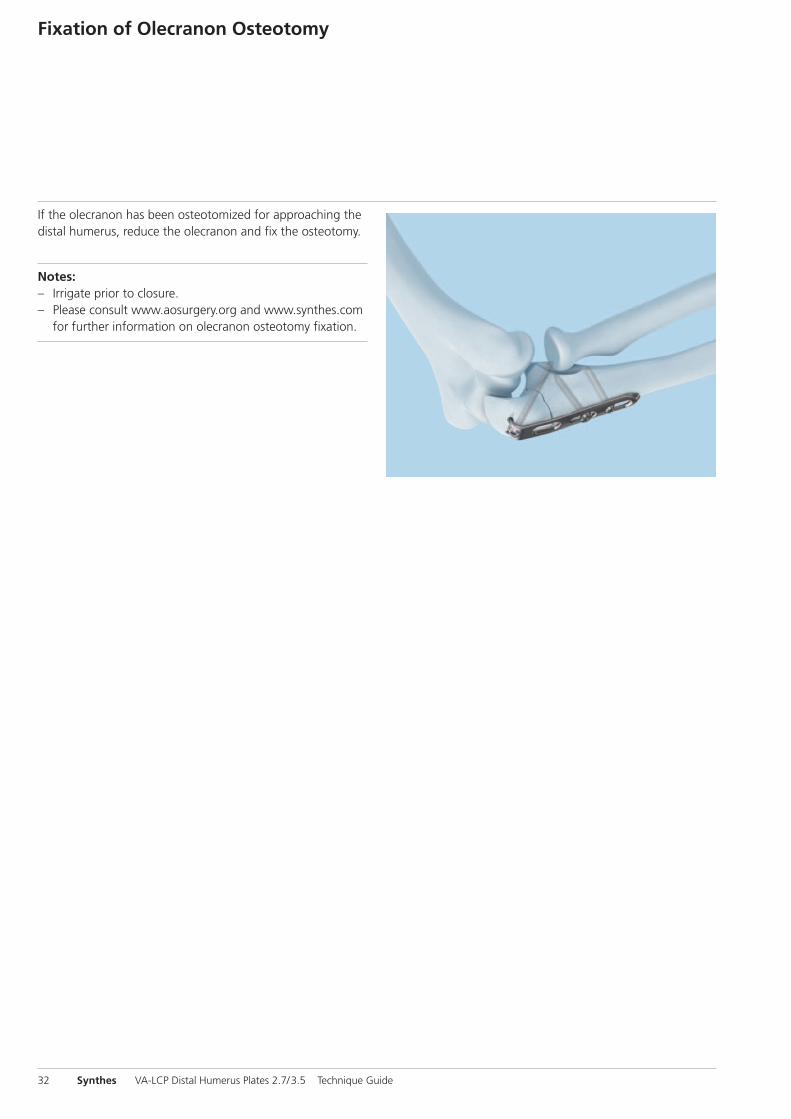
If the olecranon has been osteotomized for approaching thedistal humerus, reduce the olecranon and fix the osteotomy.
Notes:– Irrigate prior to closure.– Please consult www.aosurgery.org and www.synthes.com
for further information on olecranon osteotomy fixation.

VA-LCP Distal Humerus Plates 2.7/3.5 Technique Guide Synthes 33
Implant Removal
Instruments
314.030 Screwdriver Shaft, hexagonal, small, � 2.5 mmor314.116 Screwdriver Shaft Stardrive 3.5, T15, self-holding, for AO / ASIF Quick Coupling
314.467 Screwdriver Shaft, Stardrive, T8, self-holding
311.431 Handle with Quick Coupling
309.521 Extraction Screw for Screws � 3.5 mm
309.510 Extraction Screw, conical, for Screws � 1.5 and 2.0 mm
To remove the implants, unlock all locking screws before re-moving them completely. Failure to unlock all lockingscrews may cause plate rotation while the last screw is beingremoved, which may damage the soft tissue. If the lockingscrews can not be removed with the screwdriver (e.g. the re-cess of the screw is damaged or the locking screw is stuckin the plate), use an extraction screw with left-handed thread.Loosen the screw by turning the handle counterclockwise.
Important: Ensure that the correct instrumentation is avail-able to enable trouble-free implant removal. The use of thecorrect screwdrivers (hexagonal or Stardrive) and extractionscrews is important.

34 Synthes VA-LCP Distal Humerus Plates 2.7/3.5 Technique Guide
Implants
Plates
VA-LCP Distal Humeral Plate 2.7/3.5, dorsolateral
Holes Length Right Left
3 (short) 75 mm 0X.117.203 0X.117.303
4 (medium) 88 mm 0X.117.204 0X.117.304
7 (long) 127 mm 0X.117.207 0X.117.307
9 (extra-long) 153 mm 0X.117.209 0X.117.309
11 179 mm 0X.117.211S* 0X.117.311S*
13 205 mm 0X.117.213S* 0X.117.313S*
VA-LCP Distal Humeral Plate 2.7/3.5, dorsolateral,with lateral support
Holes Length Right Left
3 (short) 75 mm 0X.117.003 0X.117.103
4 (medium) 88 mm 0X.117.004 0X.117.104
7 (long) 127 mm 0X.117.007 0X.117.107
9 (extra-long) 153 mm 0X.117.009 0X.117.109
11 179 mm 0X.117.011S* 0X.117.111S*
13 205 mm 0X.117.013S* 0X.117.113S*
VA-LCP Distal Humeral Plate 2.7/3.5, lateral
Holes Length Right Left
1 (short) 69 mm 0X.117.801 0X.117.901
2 (medium) 82 mm 0X.117.802 0X.117.902
5 (long) 121 mm 0X.117.805 0X.117.905
7 (extra-long) 147 mm 0X.117.807 0X.117.907
9 173 mm 0X.117.809S* 0X.117.909S*
11 199 mm 0X.117.811S* 0X.117.911S*
X=2: Stainless steelX=4: TitaniumAll plates and screws are also available sterile packed. For sterile implants, add suffix “S” to article number.*Only available sterile

VA-LCP Distal Humerus Plates 2.7/3.5 Technique Guide Synthes 35
VA-LCP Distal Humeral Plate 2.7/3.5, medial
Holes Length Right Left
1 (short) 69 mm 0X.117.401 0X.117.501
2 (medium) 82 mm 0X.117.402 0X.117.502
4 (long) 108 mm 0X.117.404 0X.117.504
6 (extra-long) 134 mm 0X.117.406 0X.117.506
8 160 mm 0X.117.408S* 0X.117.508S*
10 186 mm 0X.117.410S* 0X.117.510S*
VA-LCP Distal Humeral Plate 2.7/3.5, medial,with Extension
Holes Length Right Left
1 (short) 72 mm 0X.117.601 0X.117.701
2 (medium) 85 mm 0X.117.602 0X.117.702
4 (long) 111 mm 0X.117.604 0X.117.704
6 (extra-long) 137 mm 0X.117.606 0X.117.706
8 163 mm 0X.117.608S* 0X.117.708S*
10 189 mm 0X.117.610S* 0X.117.710S*
X=2: Stainless steelX=4: TitaniumAll plates and screws are also available sterile packed. For sterile implants, add suffix “S” to article number.*Only available sterile

36 Synthes VA-LCP Distal Humerus Plates 2.7/3.5 Technique Guide
Implants
Screws
Distal screws
0X.211.010– VA Locking Screw Stardrive � 2.7 mm 0X.211.060 (head 2.4), self-tapping, length 10–60 mm
Shaft screws
X12.102– Locking Screw Stardrive � 3.5 mm, X12.124 self-tapping, length 12–60 mmorX13.012– Locking Screw � 3.5 mm, self-tapping,X13.060 length 12–60 mm
X=2: Stainless steelX=4: TitaniumAll plates and screws are also available sterile packed. For sterile implants, add suffix “S” to article number.
0X.118.510– Low Profile Metaphyseal Compression 0X.118.570 Screw Stardrive � 2.7 mm, self-tapping, length 10–70 mm
X01.760– Cortex Screw Stardrive � 2.4 mm, X01.790 self-tapping, length 10– 40 mm
X04.810– Cortex Screw � 3.5 mm, self-tapping, X04.860 length 10–60 mmor0X.200.012– Cortex Screw Stardrive � 3.5 mm, 0X.200.060 self-tapping, length 12–60 mm

VA-LCP Distal Humerus Plates 2.7/3.5 Technique Guide Synthes 37
Trial Implants
03.117.004 Trial Implant for VA-LCP Distal HumeralPlate 2.7/3.5, dorsolateral, with lateralsupport, right, medium, 4 holes, length 88 mm, Stainless Steel
03.117.104 Trial Implant for VA-LCP Distal HumeralPlate 2.7/3.5, dorsolateral, with lateralsupport, left, medium, 4 holes, length 88 mm, Stainless Steel
03.117.802 Trial Implant for VA-LCP Distal HumeralPlate 2.7 / 3.5, lateral, right, medium,2 holes, length 82 mm, Stainless Steel
03.117.902 Trial Implant for VA-LCP Distal HumeralPlate 2.7 / 3.5, lateral, left, medium, 2 holes,length 82 mm, Stainless Steel

38 Synthes VA-LCP Distal Humerus Plates 2.7/3.5 Technique Guide
Implants
03.117.602 Trial Implant for VA-LCP Distal HumeralPlate 2.7/3.5, medial, with lateral support,right, medium, 2 holes, length 85 mm,Stainless Steel
03.117.702 Trial Implant for VA-LCP Distal HumeralPlate 2.7/3.5, medial, with lateral support,left, medium, 2 holes, length 85 mm,Stainless Steel

VA-LCP Distal Humerus Plates 2.7/3.5 Technique Guide Synthes 39
Instruments
309.521 Extraction Screw for Screws � 3.5 mm
309.510 Extraction Screw, conical, for Screws � 1.5 and 2.0 mm
310.250 Drill Bit � 2.5 mm, length 110 / 85 mm,2-flute, for Quick Coupling
311.431 Handle with Quick Coupling
310.284 LCP Drill Bit � 2.8 mm with Stop, length 165 mm, 2-flute, for Quick Coupling
314.467 Screwdriver Shaft, Stardrive, T8,self-holding
319.010 Depth Gauge for Screws � 2.7 to 4.0 mm,measuring range up to 60 mm
314.030 Screwdriver Shaft, hexagonal, small, � 2.5 mm
323.062 Drill Bit � 2.0 mm, with double marking,length 140 /115 mm, 3-flute, for Quick Coupling
311.320 Tap for Cortex Screws � 3.5 mm, length 110 /50 mm

314.116 Screwdriver Shaft Stardrive 3.5, T15, self-holding, for AO / ASIF Quick Coupling
323.027 LCP Drill Sleeve 3.5, for Drill Bits � 2.8 mm
323.360 Universal Drill Guide 3.5
03.110.005 Handle for Torque Limiters 0.4 / 0.8 /1.2 Nm
03.110.002 Torque Limiter, 1.2 Nm, with AO / ASIF Quick Coupling
03.118.001 Periarticular Reduction Forceps,with pointed ball tips � 6.5 mm, small
40 Synthes VA-LCP Distal Humerus Plates 2.7/3.5 Technique Guide
Instruments

314.070 Screwdriver, hexagonal, small, � 2.5 mm,with Groove
03.118.007 Depth Gauge, percutaneous
03.211.002 VA-LCP Drill Sleeve 2.7, for Drill Bits � 2.0 mm
511.773 Torque Limiter, 1.5 Nm, for AO/ASIF Quick Coupling
329.291 Bending Pliers for Clavicular Plates,length 227 mm
329.300 Bending Press, length 400 mm
329.150 Bending Pliers for Plates 2.4 to 4.0,length 230 mm
VA-LCP Distal Humerus Plates 2.7/3.5 Technique Guide Synthes 41

42 Synthes VA-LCP Distal Humerus Plates 2.7/3.5 Technique Guide
Sets
Vario Cases
01.107.X01 VA-LCP Elbow Plates 2.7/3.5, CompleteSet, in Modular Tray, Vario Case System
Or01.107.X02 VA-LCP Elbow 2.7/3.5, Distal Humeral Plates for Perpendicular Arrangement and Olecranon PlatesOr01.107.X03 VA-LCP Elbow 2.7/3.5, Distal Humeral Plates for Parallel Arrangement and Olecranon PlatesOr01.107.X04 VA-LCP Elbow 2.7/3.5, Distal Humeral Plates for Perpendicular and Parallel Arrangement and Olecranon Plates
01.118.006 Screw Insertion Instruments for Lockingand Cortex Screws 2.7, in Modular Tray
01.122.013 Small Fragment Basic Instruments, in Modular Tray, Vario Case System
01.122.015 Screw Insertion Instruments 3.5/4.0, in Modular Tray, Vario Case System
Optional sets
01.107.005 Trial Implants for VA-LCP Elbow Plates2.7/3.5, in Modular Tray, Vario CaseSystem
01.122.014 Small Fragment Reduction Instruments, in Modular Tray, Vario Case System
X = 0: Stainless steelX = 1: Titanium

VA-LCP Distal Humerus Plates 2.7/3.5 Technique Guide Synthes 43
Bibliography
Kaiser T, Brunner A, Hohendorff B, Ulmar B, Babst R. Treat-ment of supra- and intra-articular fractures of the distalhumerus with the LCP Distal Humerus Plate: a 2-year follow-up. J Shoulder Elbow Surg 2011; 20:206 –212.
Schuster I, Korner J, Arzdorf M, Schwieger K, Diederichs G,Linke B. Mechanical Comparison in Cadaver Specimens ofThree Different 90-Degree Double-Plate Osteosyntheses forSimulated C2-Type Distal Humerus Fractures With VaryingBone Densities. J Orthop Trauma 2008; 22(2):113 –120.
Stoffel K, Cunneen S, Morgan R, Nicholls R, Stachowiak G.Comparative stability of perpendicular versus parallel double-locking plating systems in osteoporotic comminuted distalhumerus fractures. J Orthop Res 2008; 26(6):778 –784.
Sanchez-Sotelo J, Torchia ME, O’Driscoll SW. Complex DistalHumeral Fractures: Internal Fixation with a Principle-BasedParallel-Plate Technique. J Bone Joint Surg Am 2007;89:961–969.

44 Synthes VA-LCP Distal Humerus Plates 2.7/3.5 Technique Guide


0123All technique guides are available as PDF files at www.synthes.com / lit
Ö036.001.366öAAPä
036.
001.
366
vers
ion
AA
05
/ 20
1230
1011
48
© S
ynth
es, I
nc. o
r its
aff
iliat
es
Subj
ect
to m
odifi
catio
ns
Synt
hes,
LC
P, S
tard
rive
and
Vario
Cas
e ar
e tr
adem
arks
of
Synt
hes,
Inc.
or
its a
ffili
ates