Embed Size (px)
Citation preview
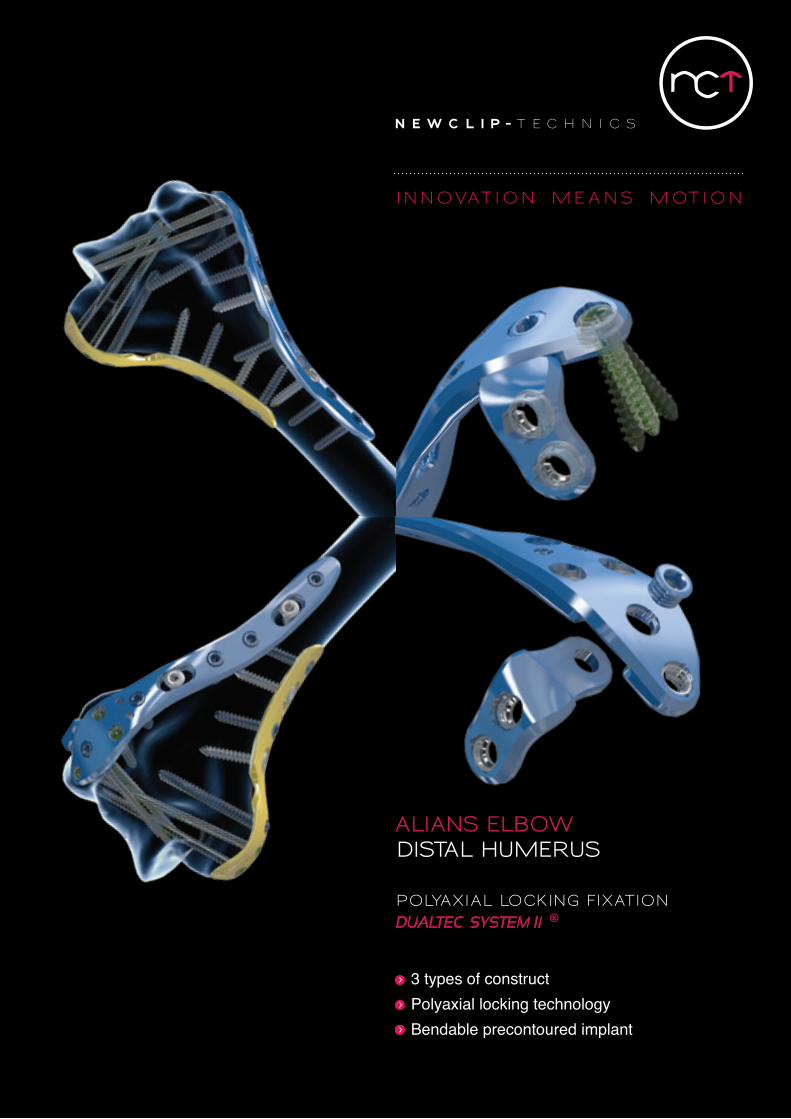
POLYAXIAL LOCKING FIXATION
3 types of constructPolyaxial locking technology Bendable precontoured implant
ALIANS ELBOWdIStAL humEruS
INN O VAT I O N mE A N S m OT I O N
INN O VAT I O N mE A N S m OT I O N
A LI A NS ELB O W
T ECHNI C A L FE AT UR ES
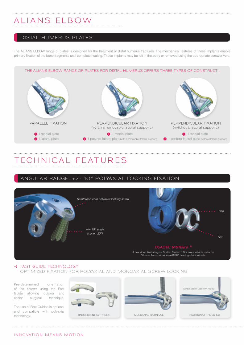
The ALIANS ELBOW range of plates is designed for the treatment of distal humerus fractures. The mechanical features of these implants enable primary fixation of the bone fragments until complete healing. These implants may be left in the body or removed using the appropriate screwdrivers.
Pre-determined orientation of the screws using the Fast Guide allowing quicker and easier surgical technique.
The use of Fast Guides is optional and compatible with polyaxial technology.
FAST GUIDE TECHNOLOGYOPTImIzED FIXATION FOR POLYAXIAL AND mONOAXIAL SCREW LOCKING
A new video illustrating our Dualtec System II ® is now available under the “Videos/ Technical principle/DTS2” heading of our website.
Reinforced core polyaxial locking screw
+/− 10° angle (cone : 20°)
Clip
DISTAL HUmERUS PLATES
ANGULAR RANGE: +/- 10° POLYAXIAL LOCKING FIXATION
1 medial plate1 lateral plate
1 medial plate1 postero-lateral plate (with a removable lateral support)
1 medial plate1 postero-lateral plate (without lateral support)
PARALLEL FIXATION PERPENDICULAR FIXATION (with a removable lateral support)
PERPENDICULAR FIXATION (without lateral support)
THE ALIANS ELBOW RANGE OF PLATES FOR DISTAL HUmERUS OFFERS THREE TYPES OF CONSTRUCT :
RADIolucenT FAST GuIDe
Nut
Screw length leSS than 45 mm
InSeRTIon oF The ScRewMonoAxIAl TechnIque

Removable lateral support
POSTERO-LATERAL PLATE
Stemming from an innovative design technique, and based on the modelling of the bone surface, this generation of implants claims optimal anatomical congruence.
To compensate for anatomical variations of the distal humerus, medial and lateral implants include metaphyseal bendable sections. Bending is only allowed on these sections.
LATERAL PLATE
mEDIAL PLATE
PRECONTOURED ImPLANT
A COmPREHENSIVE RANGE OF PLATES
Slotted holes for cortical compression Ø3.5 mm screws
DTS2 polyaxial holes for locking and non-locking Ø2.8 mm screws
Bendable sections
holes for locking and non-locking Ø3.5 mm screws

INN O VAT I O N mE A N S m OT I O N
FIX AT I O N T ECHNI Q UE
ETAPE 2
lock the Fast Guide onto the medial plate. Adjust the position of the plate using the slotted hole.
lock the Fast Guide onto the lateral plate. Adjust the position of the plate using the slotted hole.
when monoaxial screwing is possible, insert the guide gauge in the Fast Guide, drill using a Ø2.3 mm drill bit, and directly check the depth of the drilling on the graduations of the guide gauge.
when monoaxial screwing is possible, insert the guide gauge in the Fast Guide, drill using the Ø2.3 mm drill bit, and directly check the depth of the drilling on the graduations of the guide gauge.
Polyaxial technique : The distal holes allow for polyaxial screw placement if necessary. For this purpose, screw the polyaxial drill guide into the plate hole, position it as appropriate, lock it and drill using the Ø2.3 mm drill bit. This method does not require the removal of the Fast Guide.
Remove the Fast Guide if need be, drill using the Ø2.7 mm drill bit and insert the last Ø3.5 mm distal screw.
Polyaxial technique : The distal holes allow for polyaxial screw placement if necessary. For this purpose, screw the polyaxial drill guide into the plate hole, position it as appropriate, lock it and drill using the Ø2.3 mm drill bit. This method does not require the removal of the Fast Guide.
OPTION 1 : PARALLEL FIXATION USING THE LATERAL PLATE
FIXATION OF THE mEDIAL PLATE
FIXATION OF THE LATERAL OR POSTERO-LATERAL PLATE
STAGE 1
STAGE 2
FINAL RESULT
Insert the Ø2.8 mm distal screws through the Fast Guide.
Insert the Ø2.8 mm distal screws through the Fast Guide.
Remove the Fast Guide if need be, drill using the Ø2.7 mm drill bit and insert the last Ø3.5 mm distal screw.complete the fixation by inserting all the remaining Ø3.5 mm diaphyseal screws.
FIXATION OF THE LATERAL PLATE

The AlIAnS elBow postero-lateral plate can be fitted to several types of fracture. It is possible to remove the lateral support. In this case, a non-locking Ø3.5 mm screw can be inserted in the cleared hole.
lock the Fast Guide onto the postero-lateral plate. Adjust the position of the plate using the slotted hole.
when monoaxial screwing is possible, insert the guide gauge in the Fast Guide, drill using the Ø2.3 mm drill bit, and directly check the depth of the drilling on the graduations of the guide gauge.
Polyaxial technique : The distal holes allow for polyaxial screw placement if necessary. For this purpose, screw the polyaxial drill guide into the plate hole, position it as appropriate, lock it and drill using the Ø2.3 mm drill bit. This method does not require the removal of the Fast Guide.
OPTION 2 : PERPENDICULAR FIXATION USING THE POSTERO-LATERAL PLATE
In the described method, the procedure begins with the fixation of the medial plate, followed by the lateral or postero-lateral plates. however, the fixation order may be reversed.
The monoaxial fixation technique of the Ø2.8 mm epiphyseal screws requires screw length of less than 45 mm.
REmARKS
FINAL RESULT WITH LATERAL SUPPORT FINAL RESULT WITHOUT LATERAL SUPPORT
Removable lateral support : in the case of a perpendicular fixation, the lateral support enables the insertion of 2 additional polyaxial screws, from the lateral to the medial column of the distal humerus.
Insert the Ø2.8 mm distal screws through the Fast Guide.
Remove the Fast Guide if need be, drill using the Ø2.7 mm drill bit and insert the last Ø3.5 mm distal screw.complete the fixation by inserting all the remaining Ø3.5 mm diaphyseal screws.
FIXATION OF THE POSTERO-LATERAL PLATE

INN O VAT I O N mE A N S m OT I O N
mEDIAL PLATES
Ref. DescriptionNTSM1 Distal humeral medial plate – Size 1 - Symmetrical - 7 holes - l 77 mm
nTSM2 Distal humeral medial plate - Size 2 - Symmetrical - 10 holes - l 111 mm
NTSM3 Distal humeral medial plate - Size 3 - Symmetrical - 13 holes - l 149 mm
NTSM4 Distal humeral medial plate - Size 4 - Symmetrical - 16 holes - l 186 mm
LATERAL PLATES
Ref. DescriptionNTGL1 Distal humeral lateral plate - Size 1 - left - 7 holes - l 72 mm
nTDl1 Distal humeral lateral plate - Size 1 - Right - 7 holes - l 72 mm
nTGl2 Distal humeral lateral plate - Size 2 - left - 9 holes - l 93 mm
nTDl2 Distal humeral lateral plate - Size 2 - Right - 9 holes - l 93 mm
NTGL3 Distal humeral lateral plate - Size 3 - left - 12 holes - l 131 mm
nTDl3 Distal humeral lateral plate - Size 3 - Right - 12 holes - l 131 mm
NTGL4 Distal humeral lateral plate - Size 4 - left - 15 holes - l 169 mm
nTDl4 Distal humeral lateral plate - Size 4 - Right - 15 holes - l 169 mm
NTGL5 Distal humeral lateral plate - Size 5 - left - 18 holes - l 207 mm
nTDl5 Distal humeral lateral plate - Size 5 - Right - 18 holes - l 207 mm
POSTERO-LATERAL PLATES
Ref. DescriptionnTGq1 Distal humeral postero-lateral plate - Size 1 - left - 9 holes - l 74 mm
nTDq1 Distal humeral postero-lateral plate - Size 1 - Right - 9 holes - l 74 mm
nTGq2 Distal humeral postero-lateral plate - Size 2 - left - 11 holes - l 100 mm
nTDq2 Distal humeral postero-lateral plate - Size 2 - Right - 11 holes - l 100 mm
nTGq3 Distal humeral postero-lateral plate - Size 3 - left - 14 holes - l 137 mm
nTDq3 Distal humeral postero-lateral plate - Size 3 - Right - 14 holes - l 137 mm
nTGq4 Distal humeral postero-lateral plate - Size 4 - left - 17 holes - l 175 mm
nTDq4 Distal humeral postero-lateral plate - Size 4 - Right - 17 holes - l 175 mm
nTGq5 Distal humeral postero-lateral plate - Size 5 - left - 20 holes - l 213 mm
nTDq5 Distal humeral postero-lateral plate - Size 5 - Right - 20 holes - l 213 mm
ImP L A N T R EFER EN CES
Man
ufac
ture
r : n
ewc
lIP
Tec
hn
IcS
(nc
T) –
Iq/R
De/
Bro
chur
e Al
ians
elb
ow e
d1 d
u 08
/02/
2013
-

TDT SCREWS Ø2,8 mm*
Ref. DescriptionTDT2.8l10 DTS2 polyaxial locking screw (reinforced core) - Ø2.8mm - l10 mm
TDT2.8l12 DTS2 polyaxial locking screw (reinforced core) - Ø2.8mm - l12 mm
TDT2.8l14 DTS2 polyaxial locking screw (reinforced core) - Ø2.8mm - l14 mm
TDT2.8l16 DTS2 polyaxial locking screw (reinforced core) - Ø2.8mm - l16 mm
TDT2.8l18 DTS2 polyaxial locking screw (reinforced core) - Ø2.8mm - l18 mm
TDT2.8l20 DTS2 polyaxial locking screw (reinforced core) - Ø2.8mm - l20 mm
TDT2.8l22 DTS2 polyaxial locking screw (reinforced core) - Ø2.8mm - l22 mm
TDT2.8l24 DTS2 polyaxial locking screw (reinforced core) - Ø2.8mm - l24 mm
TDT2.8l26 DTS2 polyaxial locking screw (reinforced core) - Ø2.8mm - l26 mm
TDT2.8l28 DTS2 polyaxial locking screw (reinforced core) - Ø2.8mm - l28 mm
TDT2.8l30 DTS2 polyaxial locking screw (reinforced core) - Ø2.8mm - l30 mm
TDT2.8l32 DTS2 polyaxial locking screw (reinforced core) - Ø2.8mm - l32 mm
TDT2.8l34 DTS2 polyaxial locking screw (reinforced core) - Ø2.8mm - l34 mm
TDT2.8l36 DTS2 polyaxial locking screw (reinforced core) - Ø2.8mm - l36 mm
TDT2.8l38 DTS2 polyaxial locking screw (reinforced core) - Ø2.8mm - l38 mm
TDT2.8l40 DTS2 polyaxial locking screw (reinforced core) - Ø2.8mm - l40 mm
TDT2.8l45 DTS2 polyaxial locking screw (reinforced core) - Ø2.8mm - l45 mm
TDT2.8l50 DTS2 polyaxial locking screw (reinforced core) - Ø2.8mm - l50 mm
TDT2.8l55 DTS2 polyaxial locking screw (reinforced core) - Ø2.8mm - l55 mm
TDT2.8l60 DTS2 polyaxial locking screw (reinforced core) - Ø2.8mm - l60 mm
RDT SCREWS Ø2,8 mm*
Ref. DescriptionRDT2.8l10 DTS2 non-locking screw (reinforced core) - Ø2.8mm - l10 mm
RDT2.8l12 DTS2 non-locking screw (reinforced core) - Ø2.8mm - l12 mm
RDT2.8l14 DTS2 non-locking screw (reinforced core) - Ø2.8mm - l14 mm
RDT2.8l16 DTS2 non-locking screw (reinforced core) - Ø2.8mm - l16 mm
RDT2.8l18 DTS2 non-locking screw (reinforced core) - Ø2.8mm - l18 mm
RDT2.8l20 DTS2 non-locking screw (reinforced core) - Ø2.8mm - l20 mm
RDT2.8l22 DTS2 non-locking screw (reinforced core) - Ø2.8mm - l22 mm
RDT2.8l24 DTS2 non-locking screw (reinforced core) - Ø2.8mm - l24 mm
RDT2.8l26 DTS2 non-locking screw (reinforced core) - Ø2.8mm - l26 mm
RDT2.8l28 DTS2 non-locking screw (reinforced core) - Ø2.8mm - l28 mm
RDT2.8l30 DTS2 non-locking screw (reinforced core) - Ø2.8mm - l30 mm
RDT2.8l32 DTS2 non-locking screw (reinforced core) - Ø2.8mm - l32 mm
RDT2.8l34 DTS2 non-locking screw (reinforced core) - Ø2.8mm - l34 mm
RDT2.8l36 DTS2 non-locking screw (reinforced core) - Ø2.8mm - l36 mm
RDT2.8l38 DTS2 non-locking screw (reinforced core) - Ø2.8mm - l38 mm
RDT2.8l40 DTS2 non-locking screw (reinforced core) - Ø2.8mm - l40 mm
RDT2.8l45 DTS2 non-locking screw (reinforced core) - Ø2.8mm - l45 mm
RDT2.8l50 DTS2 non-locking screw (reinforced core) - Ø2.8mm - l50 mm
RDT2.8l55 DTS2 non-locking screw (reinforced core) - Ø2.8mm - l55 mm
RDT2.8l60 DTS2 non-locking screw (reinforced core) - Ø2.8mm - l60 mm
QOT SCREWS Ø3,5 mm*
Ref. DescriptionqoT3.5l10 non-locking screw Ø3.5mm - l10 mm
qoT3.5l12 non-locking screw Ø3.5mm - l12 mm
qoT3.5l14 non-locking screw Ø3.5mm - l14 mm
qoT3.5l16 non-locking screw Ø3.5mm - l16 mm
qoT3.5l18 non-locking screw Ø3.5mm - l18 mm
qoT3.5l20 non-locking screw Ø3.5mm - l20 mm
qoT3.5l22 non-locking screw Ø3.5mm - l22 mm
qoT3.5l24 non-locking screw Ø3.5mm - l24 mm
qoT3.5l26 non-locking screw Ø3.5mm - l26 mm
qoT3.5l28 non-locking screw Ø3.5mm - l28 mm
qoT3.5l30 non-locking screw Ø3.5mm - l30 mm
qoT3.5l32 non-locking screw Ø3.5mm - l32 mm
qoT3.5l34 non-locking screw Ø3.5mm - l34 mm
qoT3.5l36 non-locking screw Ø3.5mm - l36 mm
qoT3.5l38 non-locking screw Ø3.5mm - l38 mm
qoT3.5l40 non-locking screw Ø3.5mm - l40 mm
qoT3.5l45 non-locking screw Ø3.5mm - l45 mm
qoT3.5l50 non-locking screw Ø3.5mm - l50 mm
qoT3.5l55 non-locking screw Ø3.5mm - l55 mm
qoT3.5l60 non-locking screw Ø3.5mm - l60 mm
SOT SCREWS Ø3,5 mm*
Ref. DescriptionSoT3.5l10 locking screw Ø3.5mm - l10 mm
SoT3.5l12 locking screw Ø3.5mm - l12 mm
SOT3.5L14 locking screw Ø3.5mm - l14 mm
SoT3.5l16 locking screw Ø3.5mm - l16 mm
SoT3.5l18 locking screw Ø3.5mm - l18 mm
SoT3.5l20 locking screw Ø3.5mm - l20 mm
SoT3.5l22 locking screw Ø3.5mm - l22 mm
SoT3.5l24 locking screw Ø3.5mm - l24 mm
SoT3.5l26 locking screw Ø3.5mm - l26 mm
SoT3.5l28 locking screw Ø3.5mm - l28 mm
SoT3.5l30 locking screw Ø3.5mm - l30 mm
SoT3.5l32 locking screw Ø3.5mm - l32 mm
SOT3.5L34 locking screw Ø3.5mm - l34 mm
SoT3.5l36 locking screw Ø3.5mm - l36 mm
SoT3.5l38 locking screw Ø3.5mm - l38 mm
SoT3.5l40 locking screw Ø3.5mm - l40 mm
SOT3.5L45 locking screw Ø3.5mm - l45 mm
SoT3.5l50 locking screw Ø3.5mm - l50 mm
SOT3.5L55 locking screw Ø3.5mm - l55 mm
SoT3.5l60 locking screw Ø3.5mm - l60 mm
* Green anodized * Golden anodized
* Fuchsia anodized* Blue anodized .
CT SCREWS Ø3,5 mm
Ref. DescriptioncT3.5l10 Standard cortical screw Ø3.5mm - l10 mm
cT3.5l12 Standard cortical screw Ø3.5mm - l12 mm
cT3.5l14 Standard cortical screw Ø3.5mm - l14 mm
cT3.5l16 Standard cortical screw Ø3.5mm - l16 mm
cT3.5l18 Standard cortical screw Ø3.5mm - l18 mm
cT3.5l20 Standard cortical screw Ø3.5mm - l20 mm
cT3.5l22 Standard cortical screw Ø3.5mm - l22 mm
cT3.5l24 Standard cortical screw Ø3.5mm - l24 mm
cT3.5l26 Standard cortical screw Ø3.5mm - l26 mm
cT3.5l28 Standard cortical screw Ø3.5mm - l28 mm
cT3.5l30 Standard cortical screw Ø3.5mm - l30 mm
cT3.5l32 Standard cortical screw Ø3.5mm - l32 mm
cT3.5l34 Standard cortical screw Ø3.5mm - l34 mm
cT3.5l36 Standard cortical screw Ø3.5mm - l36 mm
cT3.5l38 Standard cortical screw Ø3.5mm - l38 mm
cT3.5l40 Standard cortical screw Ø3.5mm - l40 mm
Man
ufac
ture
r : n
ewc
lIP
Tec
hn
IcS
(nc
T) –
Iq/R
De/
Bro
chur
e Al
ians
elb
ow e
d1 d
u 08
/02/
2013
-

INSTRUmENTS
Ref. Description qtyAnc082e hex screwdriver 2.0 mm 1
Anc083c hex screwdriver 2.5 mm 2
Anc102l Depth gauge for DTS2 screws - long length 1
Anc103 hex safety key 2.0 mm 1
Anc107 hex safety key 2.5 mm 1
Anc124l Depth gauge for Ø3.5 mm screws – long length 1
Anc160 Prehensor for fast guide 1
Anc256e Drill bit Ø2.7mm - l180 mm 2
Anc259e Guide gauge Ø2.7 mm for locking screws - long length 2
Anc261e Guide gauge Ø2.7 mm for non-locking screws - long length 1
Anc287 Drill bit Ø2.3 mm - l180 mm 2
Anc305 DTS2 drill guide Ø2.3 mm 2
Anc306 Guide gauge Ø2.3 mm for non-locking screws 1
Anc309 obturator for drill guide Ø2.3 mm 1
Anc313 Fast Guide for nTSMx plates 1
Anc314 Fast Guide for nTGlx plates 1
Anc315 Fast Guide for nTDlx plates 1
Anc316 Fast Guide for nTGqx plates 1
Anc317 Fast Guide for nTDqx plates 1
33.0216.210 Pins Ø1.6 l 210 mm 5
33.0220.210 Pins Ø2.0 l 210 mm 5
Anc350 handle Ao Ø4.5 mm – size 1 1
Anc351 handle Ao Ø4.5 mm – size 2 1
Anc452 Bending iron 2
Anc463 hand countersink Ø3.5 mm 1
Anc296/I3 : IMPLANT SET
Anc296/B : BASe
Anc296/R : ScRew RAcK
Anc296/I1 : InSTRuMenT SeT
INST R UmEN TS R EFER EN CES
NEWCLIP TECHNICSPA de la Lande Saint Martin - 45 rue des Garottières44115 Haute Goulaine (France)Tél. : +33 (0)2 28 21 37 12 - Fax : +33 (0)2 40 63 68 [email protected] - www.newcliptechnics.com
NEWCLIP USA642 Larkfield Center Santa Rosa CA 95403, USAPhone : + 1 707 230 [email protected] - www.newclipusa.com
The information presented in this brochure is intended to demonstrate a newclIP TechnIcS product. Always refer to the package insert, product label and/or user instructions before using any newclIP TechnIcS product. Surgeons must always rely on their own clinical judgment when deciding which products and techniques to use with their patients. Products may not be available in all markets. Product availability is subject to the regulatory or medical practices that govern individual markets. Please contact your newclIP TechnIcS representative if you have questions about the availability of newclIP TechnIcS products in your area. To
en
- Al
ians
elb
ow/D
ista
l hum
erus
- ed
1 - 1
0/20
14 -
Med
ical
dev
ice
ec: c
lass
IIb
- uS
cla
ss: I
I - c
e 01
20 S
GS
uK
- Rea
d la
belin
g an
d in
stru
ctio
ns b
efor
e us
e.
REmOVAL KIT
If you have to remove AlIAnS elBow DISTAl huMeRuS implants, make sure to order the newclip Technics removal set which includes the following instruments : - Anc103 for Ø2.8 mm screws- Anc107 or Anc016 for Ø3.5 mm screws- Anc350 : Ø4.5 mm Ao quick coupling handle - Size 1