Embed Size (px)
Citation preview
Kingston Tec hnology
DATA EXPRESSRemovable SCSI Drive EnclosureWith Wide Differential I/O
User's Guide
DE100i-SWD User's Guide - Rev. C00 Kingston Technology Company
i
Kingston Tec hnology's
Data Express ®
DE100i-SWDRemovable SCSI Drive Enclosure
with 16-Bit Wide Differential I/O
User's Guide
Part No. D89-0000-0012 C00 December 1997
Kingston Technology Company17600 Newhope Street
Fountain Valley, CA 92708-9885Phone (714) 438-1850 Fax (714) 438-1847
Kingston Technology Company DE100i-SWD User's Guide - Rev. C00
ii
KINGSTON TECHNOLOGY COMPANY (“Kingston”) warrants that this product is free from defects in material andworkmanship. Subject to the conditions and limitations set forth below, Kingston will, at its option, either repair orreplace any part of this product which proves defective by reason of improper workmanship or materials. Repairparts or replacement products will be provided by Kingston on an exchange basis, and will be either new orrefurbished to be functionally equivalent to new.
This warranty does not cover any damage to this product which results from accident, abuse, misuse, natural orpersonal disaster, or any unauthorized disassembly, repair or modification.
Duration of Warranty
Lifetime Warranty: The following Kingston products are covered by this warranty for life: solid state memory (e.g.,memory modules and boards), networking adapters and. hubs (excluding power supply unit), solid state PCMCIAinterface adapters, and microprocessor upgrade products.
Seven Year Warranty: The following Kingston products are covered by this warranty for a period of seven yearsfrom the date of original retail purchase: storage enclosures, including power supply units, cables, terminators, andaccessories.
Five Year Warranty: The following Kingston products are covered by this warranty for a period of five years fromthe date of original retail purchase: networking hub power supply unit; and all other Kingston products (other thanthose products covered by a two-year or one-year warranty, as provided below).
Two Year Warranty: The following Kingston products are covered by this warranty for a period of two years fromthe date of original retail purchase: Winchester hard disk drives in a 2.5 inch, 3.5 inch or 5.25 inch form factor.
One Year Warranty: The following Kingston products are covered by this warranty for a period of one year fromthe date of original retail purchase: Winchester hard disk drives in a 1.8 inch form factor, optical reading and storageproducts, and magnetic tape storage products.
Warranty Claim Requirements
To obtain warranty service, return the defective product, freight prepaid and insured, to your local authorizedKingston dealer or distributor, or to the Kingston factory service center located at 17600 Newhope Street, FountainValley, California 92708, U.S.A. You must include the product serial number (if applicable) and a detaileddescription of the problem you are experiencing. You must also include proof of the date of original retail purchaseas evidence that the product is within the applicable warranty period. If you return the product directly to the Kingstonfactory, you must first obtain a Return Material Authorization (“RMA”) number by calling Kingston Customer Serviceat (714) 438-1810, and include the RMA number prominently displayed on the outside of your package. Productsmust be properly packaged to prevent damage in transit.
Free Technical Support
Kingston provides free technical support. If you experience any difficulty during the installation or subsequent useof a Kingston product, please contact Kingstons Technical Support department at either: (714) 435-2639 U.S.headquarters, or Kingston Germany Office at (089) 62 71 56-21, prior, to servicing your system. This warrantycovers only repair or replacement of defective Kingston products, as provided above. Kingston is not liable for, anddoes not cover under warranty, any costs associated with servicing and/or installation of Kingston products.
Disclaimers – The foregoing is the complete warranty for Kingston products and supersedes all otherwarranties and representations, whether oral or written. Except as expressly set forth above, no otherwarranties are made with respect to Kingston products and Kingston expressly disclaims all warrantiesnot stated herein, including, to the extent permitted by applicable law, any implied warranty of merchant-ability or fitness for a particular purpose. In no event will Kingston be liable to the purchaser, or to any userof the Kingston product, for any damages, expenses, lost revenues, lost savings, lost profits, or any otherincidental or consequential damages arising from the purchase, use or inability to use the Kingstonproduct, even if Kingston has been advised of the possibility of such damages.
Copyright© 1997 Kingston Technology Company. All rights reserved. Printed in the U.S.A. KingstonTechnology and the Kingston logo are trademarks of Kingston Technology Company.
Limited Warranty
DE100i-SWD User's Guide - Rev. C00 Kingston Technology Company
iii
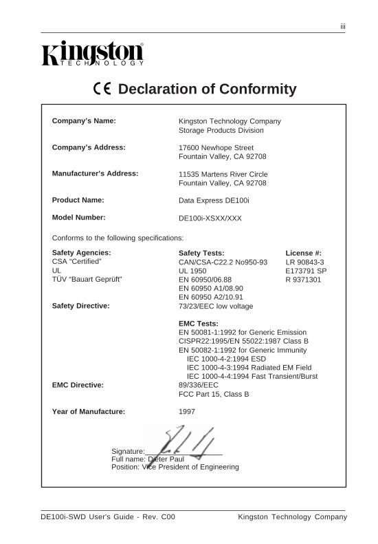
CE Declaration of Conformity
Kingston Technology CompanyStorage Products Division
17600 Newhope StreetFountain Valley, CA 92708
11535 Martens River CircleFountain Valley, CA 92708
Data Express DE100i
DE100i-XSXX/XXX
Safety Tests: License #:CAN/CSA-C22.2 No950-93 LR 90843-3UL 1950 E173791 SPEN 60950/06.88 R 9371301EN 60950 A1/08.90EN 60950 A2/10.9173/23/EEC low voltage
EMC Tests:EN 50081-1:1992 for Generic EmissionCISPR22:1995/EN 55022:1987 Class BEN 50082-1:1992 for Generic Immunity
IEC 1000-4-2:1994 ESDIEC 1000-4-3:1994 Radiated EM FieldIEC 1000-4-4:1994 Fast Transient/Burst
89/336/EECFCC Part 15, Class B
1997
Company’s Name:
Company’s Address:
Manufacturer’s Address:
Product Name:
Model Number:
Safety Agencies:CSA “Certified”ULTÜV “Bauart Geprüft”
Safety Directive:
EMC Directive:
Year of Manufacture:
Signature:___________________Full name: Dieter PaulPosition: Vice President of Engineering
Conforms to the following specifications:
Kingston Technology Company DE100i-SWD User's Guide - Rev. C00
iv
Table of Contents
DATA EXPRESS DE100i-SWD ............................................................................................... 1Packaging Materials ...................................................................................................... 1Package Contents ......................................................................................................... 2Serial Numbers .............................................................................................................. 2General Description ....................................................................................................... 3
The Receiving Frame Front Panel ...................................................................... 4The Receiving Frame Rear Panel ...................................................................... 5
DATA EXPRESS INSTALLATION .......................................................................................... 6Installing the Drive into the Carrier ................................................................................ 6
Preparation .......................................................................................................... 6Installation ............................................................................................................ 7
Installing the Receiving Frame ...................................................................................... 9Selecting the Unit Number ........................................................................................... 11SCSI Interface Connector J2 ...................................................................................... 13
APPENDICES ...................................................................................................................... 15Appendix A - Specifications/Dimensions .................................................................... 16Appendix B - Factory-Installed Options ...................................................................... 18
Hot Swap Feature .............................................................................................. 18Solenoid Drive Lock ........................................................................................... 22Appendix C - Attaching the On/Off Key to Non-Solenoid Units ....................... 23
Appendix D - Optional Accessories ............................................................................ 24Carrying Case ................................................................................................... 24Drive Cover ....................................................................................................... 25Write Protect Switch .......................................................................................... 26Drive Plug ........................................................................................................... 27
Reader's Comments .............................................................................................................. 29
DE100i-SWD User's Guide - Rev. C00 Kingston Technology Company
v
List of Figures
Figure 1: Data Express DE100i-SWD Package Contents ................................................ 1Figure 2: DE100i-SWD Receiving Frame and Carrier ....................................................... 2Figure 3: Receiving Frame Front Panel ............................................................................. 4Figure 4: Unit Number Display Conditions ......................................................................... 5Figure 5: Receiving Frame (Rear View) ............................................................................ 5Figure 6: Drive Installation Assembly ................................................................................. 7Figure 7: Typical SCSI ID Select Connections (2mm Drive Pins) .................................... 8Figure 8: Receiving Frame Connector J4 Pin Configuration ............................................. 9Figure 9: Receiving Frame Mounting Holes ..................................................................... 10Figure 10: Unit Select Switch Location ............................................................................... 12Figure A-1: Data Express Physical Dimensions ................................................................. 17Figure B-1: Attaching the Hot Swap Board .......................................................................... 19Figure B-2: Device Spin Down/Up Timer ............................................................................. 20Figure B-3: Hot Swap Board Jumper Options ..................................................................... 21Figure B-4: Solenoid Mechanism ......................................................................................... 22Figure C-1: Attaching the On/Off Key .................................................................................. 23Figure D-1: Optional Carrying Case (DX100-DE-C) ........................................................... 24Figure D-2: Optional Drive Cover (DX100-COV) ................................................................ 25Figure D-3: Optional Write Protect Switch (DX100-DEWP) ................................................ 26Figure D-4: Optional Drive Plug (DX100-PLUG) ................................................................. 27
List of Tables
Table 1: Shipping Contents .................................................................................................... 2Table 2: Receiving Frame Motherboard Connector J4 Pin Configuration ........................... 9Table 3: 16-Bit Wide Differential Unit ID Display ................................................................. 12Table 4: 68-Pin Wide Differential SCSI Interface Connector J2 Pin Assignments ............ 13
Introduction 1
DE100i-SWD User's Guide - Rev. C00 Kingston Technology Company
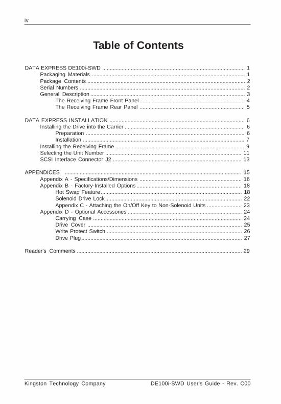
Data Express ® DE100i-SWDPackaging MaterialsThe Kingston Technology Data Express® system is shipped in a container designed toprovide protection and prevent damage during shipment. The Data Express unit wascarefully inspected before and during the packing procedure at the factory. Bent or brokenconnectors, or evidence of other damage to the Data Express should be reported to theshipper immediately. Refer to Figure 1 for the package contents.
If the wrong Data Express model has been received, please call Kingston's StorageProduct Division at (800) 435-0642. A staff member will give you a Return MaterialAuthorization (RMA) number to facilitate processing. Kingston cannot accept returns whichdo not display an RMA number on the outside of the package. Return the unit with all theoriginal packing materials.
Before removing any component from its packaging, discharge any static electricity bytouching a properly grounded metal object.
1. Cable Cover2. Alignment Tool3. Drive Lock Keys4. Receiving Frame5. Drive Carrier6. User's Guide
7. Drive Standoffs8. 6-32 by 1/4" Phillips Machine Hd. Mounting Screws9. 6-32 by 3/16" Phillips F.H. Mounting Screws
10. 1.25mm/2mm ID Select Cable11. Single Row Wire Wrap Connector
Figure 1: Data Express DE100i-SWD Package Contents
1
2
3
4
7
8
9
DATA EXPRESS
5
6
CO
MP
UT
I NG
WI T
HO
UT
LI M
I TS
TE
CH
NO
LO
GY
USER'S GUIDE
10
11
0430B
2 Introduction
Kingston Technology Company DE100i-SWD User's Guide - Rev. C00
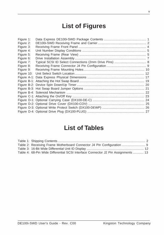
One Kingston Data Express DE100i-SWD DE100i-CSWD DE100i-RSWDSCSI System Part Number (Carrier & RF) (Carrier) (Receiving Frame)
Drive Carrier DE100i-CSWD (1) (1)
Receiving Frame DE100i-RSWD (1) (1)
Alignment Tool D45-0000-0037 (1) (1)
Phillips Mounting Screws (6-32 by 3/16” D45-0000-0001 (6) (6)F.H. to attach disk drive and cable cover)
Phillips Mounting Screws (6-32 by 1/4”) D45-0000-0004 (4) (4)to attach receiving frame to computer)
Single Row Wire Wrap Connector D16-0000-0046 (1) (1)
2mm Low Profile Interface Cable D12-1000-0081 (1) (1)
Cable Cover D10-4040-0151 (1) (1)
Drive Standoffs D45-0000-0069 (4) (4)
Drive Lock Keys D10-4050-0005 (3) (3)
User's Guide D89-0000-0012 (1) (1) (1)
Package Contents
The DE100i-SWD package contents include the following items:
If any item is missing or damaged, contact your Kingston dealer for a replacement.
Table 1: Shipping Contents
Serial Numbers
Both the Data Express receiving frame and carrier are labeled with serial numbers. Thesenumbers must be reported to the Kingston Customer Service Representative in order toreceive a Return Material Authorization (RMA) for warranty claims. Locate the serialnumber labels and record the numbers in the spaces provided below.
Receiving Frame:
Drive Carrier:
Introduction 3
DE100i-SWD User's Guide - Rev. C00 Kingston Technology Company
General Description
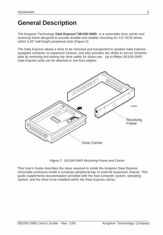
The Kingston Technology Data Express ® DE100i-SWD is a removable drive carrier andreceiving frame designed to provide durable and reliable mounting for 3.5” SCSI driveswithin 5.25" half-height peripheral slots (Figure 2).
The Data Express allows a drive to be removed and transported to another Data Express-equipped computer or expansion chassis, and also provides the ability to secure sensitivedata by removing and storing the drive safely for future use. Up to fifteen DE100i-SWDData Express units can be attached to one host adapter.
Figure 2: DE100i-SWD Receiving Frame and Carrier
This User's Guide describes the steps required to install the Kingston Data Expressremovable enclosure inside a computer peripheral bay or external expansion chassis. Thisguide supplements documentation provided with the host computer system, operatingsystem, and the drive to be installed within the Data Express carrier.
Drive Carrier
0425B
ReceivingFrame
4 Introduction
Kingston Technology Company DE100i-SWD User's Guide - Rev. C00
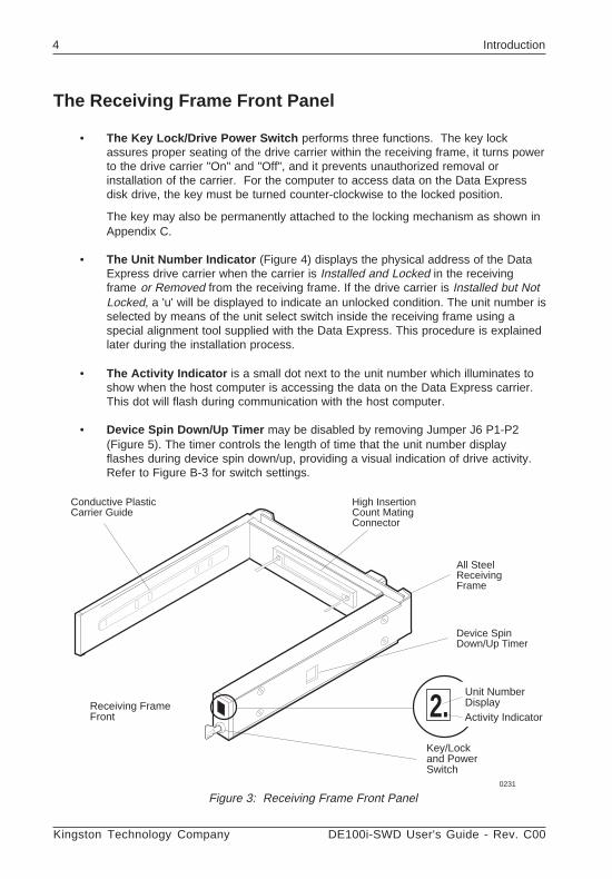
The Receiving Frame Front Panel
• The Key Lock/Drive Power Switch performs three functions. The key lockassures proper seating of the drive carrier within the receiving frame, it turns powerto the drive carrier "On" and "Off", and it prevents unauthorized removal orinstallation of the carrier. For the computer to access data on the Data Expressdisk drive, the key must be turned counter-clockwise to the locked position.
The key may also be permanently attached to the locking mechanism as shown inAppendix C.
• The Unit Number Indicator (Figure 4) displays the physical address of the DataExpress drive carrier when the carrier is Installed and Locked in the receivingframe or Removed from the receiving frame. If the drive carrier is Installed but NotLocked, a 'u' will be displayed to indicate an unlocked condition. The unit number isselected by means of the unit select switch inside the receiving frame using aspecial alignment tool supplied with the Data Express. This procedure is explainedlater during the installation process.
• The Activity Indicator is a small dot next to the unit number which illuminates toshow when the host computer is accessing the data on the Data Express carrier.This dot will flash during communication with the host computer.
• Device Spin Down/Up Timer may be disabled by removing Jumper J6 P1-P2(Figure 5). The timer controls the length of time that the unit number displayflashes during device spin down/up, providing a visual indication of drive activity.Refer to Figure B-3 for switch settings.
Figure 3: Receiving Frame Front Panel
Receiving FrameFront
Key/Lockand PowerSwitch
2.Unit NumberDisplayActivity Indicator
0231
Device SpinDown/Up Timer
Conductive PlasticCarrier Guide
High InsertionCount MatingConnector
All SteelReceivingFrame
Introduction 5
DE100i-SWD User's Guide - Rev. C00 Kingston Technology Company
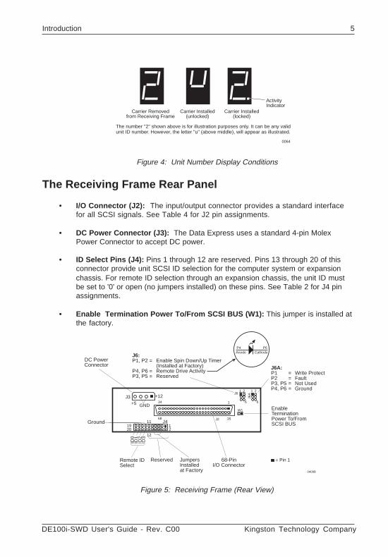
Carrier Installed(unlocked)
Carrier Installed(locked)
Carrier Removedfrom Receiving Frame
The number "2" shown above is for illustration purposes only. It can be any validunit ID number. However, the letter "u" (above middle), will appear as illustrated.
0064
ActivityIndicator
Figure 4: Unit Number Display Conditions
The Receiving Frame Rear Panel
• I/O Connector (J2): The input/output connector provides a standard interfacefor all SCSI signals. See Table 4 for J2 pin assignments.
• DC Power Connector (J3): The Data Express uses a standard 4-pin MolexPower Connector to accept DC power.
• ID Select Pins (J4): Pins 1 through 12 are reserved. Pins 13 through 20 of thisconnector provide unit SCSI ID selection for the computer system or expansionchassis. For remote ID selection through an expansion chassis, the unit ID mustbe set to '0' or open (no jumpers installed) on these pins. See Table 2 for J4 pinassignments.
• Enable Termination Power To/From SCSI BUS (W1): This jumper is installed atthe factory.
Figure 5: Receiving Frame (Rear View)
DC PowerConnector
EnableTerminationPower To/FromSCSI BUS
Remote IDSelect
68-PinI/O Connector
Ground
ID0
ID1
ID2
0408B
1920
J3
J2
J6
J4
+5
+12
GND
12
Reserved
W1
J6A
12
11
1 2
6
1 2
6
J6:P1, P2 = Enable Spin Down/Up Timer
(Installed at Factory)P4, P6 = Remote Drive ActivityP3, P5 = Reserved
J6A:P1 = Write ProtectP2 = FaultP3, P5 = Not UsedP4, P6 = Ground
JumpersInstalledat Factory
Anode CathodeP4 P6
= Pin 1
ID3
134
68 35
Kingston Technology Company DE100i-SWD User's Guide - Rev. C00
6 Installation
DATA EXPRESS INSTALLATION
Installing the Drive into the Carrier
Preparation
While performing the steps in this section, work on a soft surface to prevent excessiveshock to the drive being installed. Also refer to the manufacturer's documentationprovided with the drive.
NOTE: A #2 Phillips screwdriver will be required during this procedure.
1. Remove the drive from its protective packaging.
2. Plastic Drive Bezel: If the drive came equipped with a plastic front bezel, itmust be removed.
3. SCSI Drive Termination: Disable or remove the termination resistorpacks from the drive. Refer to the documentation provided by the drivemanufacturer for the location of these terminators or jumpers. Terminationis performed externally on the expansion chassis and not on the DataExpress unit.
4. SCSI Drive ID Select Jumpers: Locate the SCSI ID Select Jumperpositions on the disk drive, and remove any jumper plugs in this area. TheSCSI ID cable will be installed into this section of the drive.
5. SCSI ID Cable: (Figure 7) The Data Express carrier is supplied with one (1)5-wire cable. This cable is used for remote ID selection by means of theData Express Unit Select Switch inside the receiving frame. The cable isdesigned to connect to drives with 2mm ID Select connectors.
The cables are made up of black, brown, red, orange, and yellow wires.The black wire is plugged into the pin used to select ID0, the brown wireplugs into the pin for ID1, the red wire plugs into the pin for ID2 and theorange wire connects to ID3. Most drive manufacturers mark these pinswith some sort of identification which corresponds to ID0, ID1, ID2 and ID3.The yellow wire should be connected to the drive's activity signal.
Disk drives use a row of pins to provide ground to the ID signals. This rowof pins is not used when installing the ID select cable to the carrierconnector. Refer to the drive manufacturer's documentation for moreinformation.
DE100i-SWD User's Guide - Rev. C00 Kingston Technology Company
Installation 7
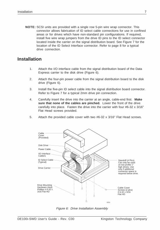
NOTE: SCSI units are provided with a single row 5-pin wire wrap connector. Thisconnector allows fabrication of ID select cable connections for use in confinedareas or for drives which have non-standard pin configurations. If required,install five wire wrap jumpers from the drive ID pins to the ID select connectorlocated inside the carrier on the signal distribution board. See Figure 7 for thelocation of the ID Select Interface connector. Refer to page 8 for a typicaldrive connection.
Installation
1. Attach the I/O interface cable from the signal distribution board of the DataExpress carrier to the disk drive (Figure 6).
2. Attach the four-pin power cable from the signal distribution board to the diskdrive (Figure 6).
3. Install the five-pin ID select cable into the signal distribution board connector.Refer to Figure 7 for a typical 2mm drive pin connection.
4. Carefully insert the drive into the carrier at an angle, cable-end first. Makesure that none of the cables are pinched. Lower the front of the drivecarefully into place. Fasten the drive into the carrier with four #6-32 x 3/16"Flat Head screws provided.
5. Attach the provided cable cover with two #6-32 x 3/16" Flat Head screws.
Drive Carrier
Disk Drive
Power Cable
I/O InterfaceCable/s
Drive MountingHardware (4ea)Phillips # 6-32 x3/16 Flat HD
ID Select Cable(Typical)
0151
CableCover(Provided)
Cable CoverScrews (2 plcs)# 6-32 x 3/16Flat HD
Standoff (4 Plcs).Can only be usedon low profile 1"high drives. Useonly if additionalconnector space isrequired below drive.
Figure 6: Drive Installation Assembly
Kingston Technology Company DE100i-SWD User's Guide - Rev. C00
8 Installation
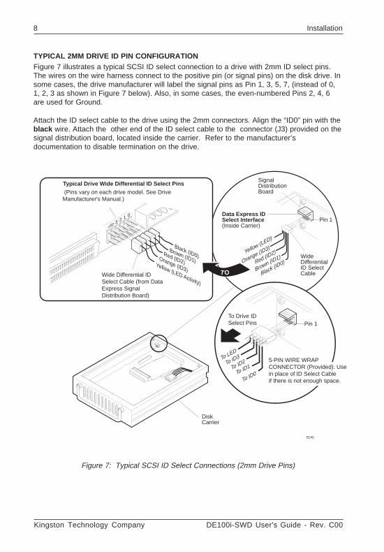
Figure 7: Typical SCSI ID Select Connections (2mm Drive Pins)
TYPICAL 2MM DRIVE ID PIN CONFIGURATIONFigure 7 illustrates a typical SCSI ID select connection to a drive with 2mm ID select pins.The wires on the wire harness connect to the positive pin (or signal pins) on the disk drive. Insome cases, the drive manufacturer will label the signal pins as Pin 1, 3, 5, 7, (instead of 0,1, 2, 3 as shown in Figure 7 below). Also, in some cases, the even-numbered Pins 2, 4, 6are used for Ground.
Attach the ID select cable to the drive using the 2mm connectors. Align the “ID0” pin with theblack wire. Attach the other end of the ID select cable to the connector (J3) provided on thesignal distribution board, located inside the carrier. Refer to the manufacturer’sdocumentation to disable termination on the drive.
Black (ID0)
Brown (ID1)
Red (ID2)
Data Express IDSelect Interface(Inside Carrier)
SignalDistributionBoard
WideDifferentialID SelectCable
Pin 1
(Pins vary on each drive model. See DriveManufacturer's Manual.)
Orange (ID3)
Yellow (LED)
T O
To Drive IDSelect Pins
To ID0To ID1To ID2 5-PIN WIRE WRAPCONNECTOR (Provided). Usein place of ID Select Cableif there is not enough space.
Pin 1
To ID3To LED
Black (ID0)Brown (ID1)
Red (ID2)Orange (ID3)
Yellow (LED Activity)Wide Differential IDSelect Cable (from DataExpress SignalDistribution Board)
Typical Drive Wide Differential ID Select Pins
0123LED
DiskCarrier
0142
DE100i-SWD User's Guide - Rev. C00 Kingston Technology Company
Installation 9
Installing the Receiving FrameThe drive should be installed into the carrier before installing the receiving frame into themounting bay of a computer or expansion chassis.
NOTE: Use a #2 Phillips screwdriver during this procedure.
1. Turn off power to the computer.
2. Open the computer system according to the manufacturer’s instructions. Ifnecessary, temporarily remove any expansion boards that may make installationdifficult.
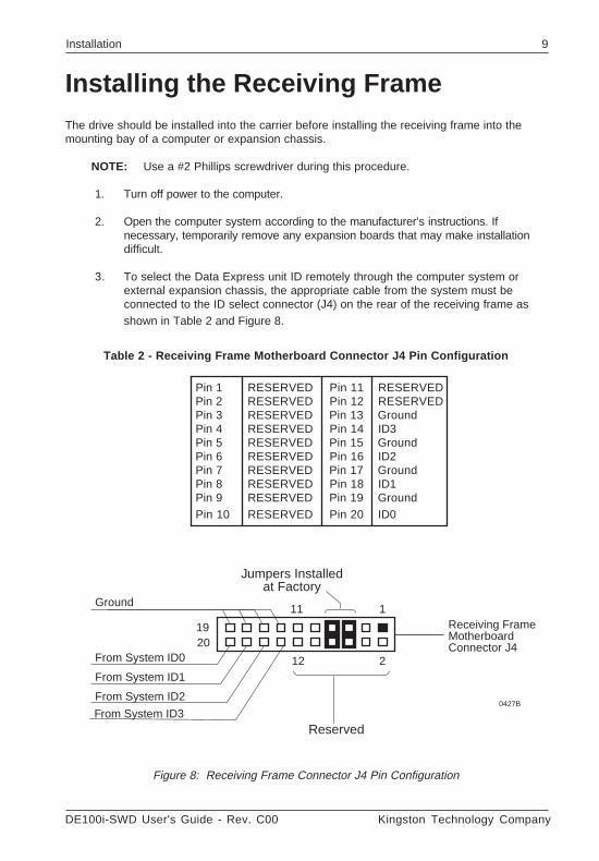
3. To select the Data Express unit ID remotely through the computer system orexternal expansion chassis, the appropriate cable from the system must beconnected to the ID select connector (J4) on the rear of the receiving frame asshown in Table 2 and Figure 8.
Table 2 - Receiving Frame Motherboard Connector J4 Pin Configuration
Pin 1 RESERVED Pin 11 RESERVEDPin 2 RESERVED Pin 12 RESERVEDPin 3 RESERVED Pin 13 GroundPin 4 RESERVED Pin 14 ID3Pin 5 RESERVED Pin 15 GroundPin 6 RESERVED Pin 16 ID2Pin 7 RESERVED Pin 17 GroundPin 8 RESERVED Pin 18 ID1Pin 9 RESERVED Pin 19 GroundPin 10 RESERVED Pin 20 ID0
Figure 8: Receiving Frame Connector J4 Pin Configuration
0427B
Receiving FrameMotherboardConnector J4
Jumpers Installedat Factory
Reserved
1920
111
212From System ID0
From System ID1
From System ID2
Ground
From System ID3
Kingston Technology Company DE100i-SWD User's Guide - Rev. C00
10 Installation
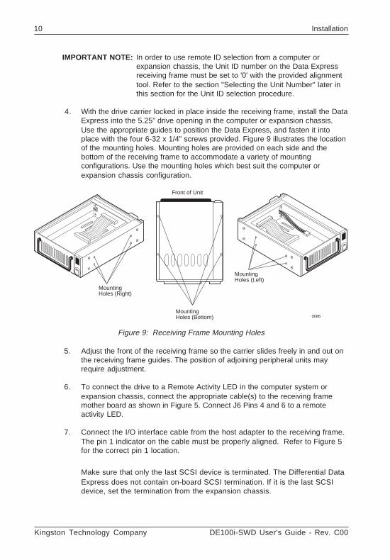
MountingHoles (Right)
MountingHoles (Bottom)
Front of Unit
MountingHoles (Left)
0086
IMPORTANT NOTE: In order to use remote ID selection from a computer orexpansion chassis, the Unit ID number on the Data Expressreceiving frame must be set to '0' with the provided alignmenttool. Refer to the section "Selecting the Unit Number" later inthis section for the Unit ID selection procedure.
4. With the drive carrier locked in place inside the receiving frame, install the DataExpress into the 5.25” drive opening in the computer or expansion chassis.Use the appropriate guides to position the Data Express, and fasten it intoplace with the four 6-32 x 1/4” screws provided. Figure 9 illustrates the locationof the mounting holes. Mounting holes are provided on each side and thebottom of the receiving frame to accommodate a variety of mountingconfigurations. Use the mounting holes which best suit the computer orexpansion chassis configuration.
Figure 9: Receiving Frame Mounting Holes
5. Adjust the front of the receiving frame so the carrier slides freely in and out onthe receiving frame guides. The position of adjoining peripheral units mayrequire adjustment.
6. To connect the drive to a Remote Activity LED in the computer system orexpansion chassis, connect the appropriate cable(s) to the receiving framemother board as shown in Figure 5. Connect J6 Pins 4 and 6 to a remoteactivity LED.
7. Connect the I/O interface cable from the host adapter to the receiving frame.The pin 1 indicator on the cable must be properly aligned. Refer to Figure 5for the correct pin 1 location.
Make sure that only the last SCSI device is terminated. The Differential DataExpress does not contain on-board SCSI termination. If it is the last SCSIdevice, set the termination from the expansion chassis.
DE100i-SWD User's Guide - Rev. C00 Kingston Technology Company
Installation 11
8. Connect the power cable from the DC power supply in the computer orexpansion chassis to the power connector on the Data Express receivingframe. Refer to Figure 5 for the Data Express receiving frame powerconnector location.
9. Replace any expansion boards that may have been removed earlier. Replacethe system cover according to the manufacturer’s instructions.
10. Reconnect any system or peripheral cables removed earlier.
11. Turn on power to the computer. If the installation has been successful, andall cables have been properly attached, the system should boot normally.Although the computer may not recognize the Data Express yet, theappropriate front panel LED indicators on the Data Express should illuminate.
NOTE: The lock on the Data Express receiving frame functions as a lockand a DC power switch for the carrier unit. The lock must beengaged (turned counterclockwise) in order to supply power to thecarrier and installed drive unit.
12. The new drive may need to be formatted or initialized prior to use with theoperating system and applications software. Refer to the drive and/or computermanufacturer's documentation for formatting information.
Selecting the Unit Number1. Verify that power is turned on to the Data Express receiving frame by turning
on the computer or external expansion chassis. A number should appear inthe unit display window if the carrier is locked in place.
2. Unlock the Data Express drive carrier and remove it from the receiving frame.A 'u' will be displayed initially when the unit is unlocked but will return to anumber when the carrier is removed from the receiving frame.
WARNING: Unlocking the carrier unit switches DC power off to the drive.Since disk drives require a short amount of time to spin down, allow about 15seconds before pulling the carrier unit out of the receiving frame to avoidpossible damage to the drive.
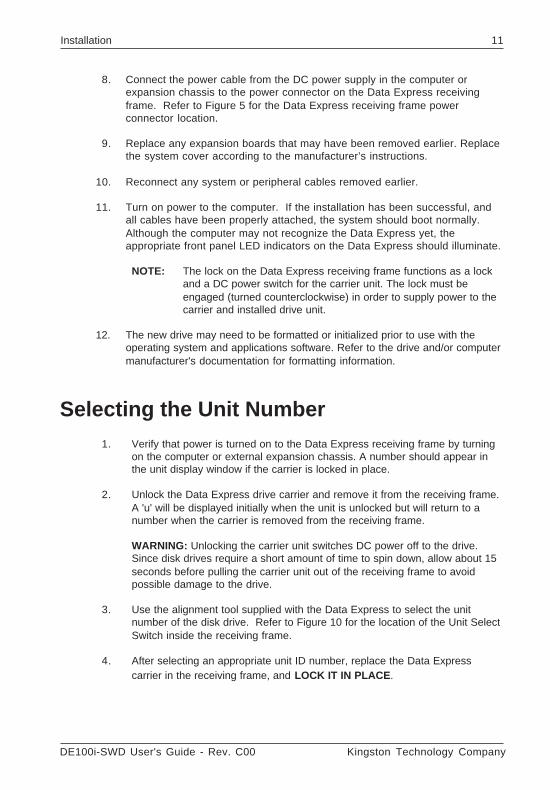
3. Use the alignment tool supplied with the Data Express to select the unitnumber of the disk drive. Refer to Figure 10 for the location of the Unit SelectSwitch inside the receiving frame.
4. After selecting an appropriate unit ID number, replace the Data Expresscarrier in the receiving frame, and LOCK IT IN PLACE .
Kingston Technology Company DE100i-SWD User's Guide - Rev. C00
12 Installation
Drive CarrierGuide
ReceivingFrame
Unit SelectRotating Switch
Drive Carrier(removed)
Unit NumberDisplay
Lockand DCPowerSwitch
Front of Unit
0179A
NOTE: The lock on the Data Express receiving frame serves two functions:1) as a lock to secure the drive; and 2) as a DC power switch forthe carrier unit. The lock must be engaged (turned counter-clockwise) in order to supply power to the drive carrier.
5. The new drive may need to be formatted or initialized prior to use with theoperating system and applications software, Refer to the drive and/orcomputer manufacturer's documentation for formatting information.
Figure 10: Unit Select Switch Location
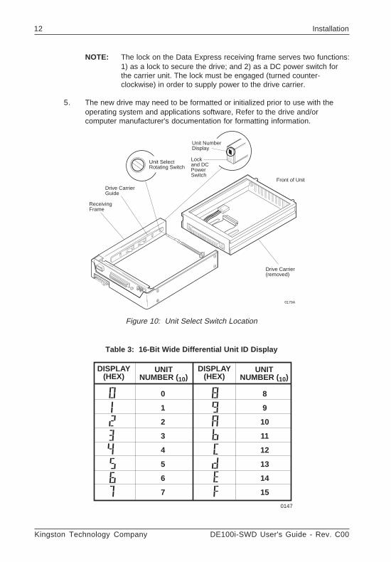
DISPLAY(HEX)
UNITNUMBER (10)
DISPLAY(HEX)
UNITNUMBER (10)
0
1
2
3
4
5
6
7
8
9
10
11
12
13
14
15
0147
Table 3: 16-Bit Wide Differential Unit ID Display
DE100i-SWD User's Guide - Rev. C00 Kingston Technology Company
Installation 13
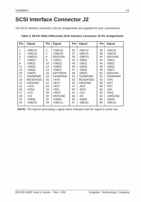
SCSI Interface Connector J2The SCSI interface connector (J2) pin assignments are supplied for your convenience.
Table 4: 68-Pin Wide Differential SCSI Interface Connector J2 Pin Assignments
NOTE: The hyphen preceding a signal name indicates that the signal is active low.
Pin Signal Pin Signal Pin Signal Pin Signal
1 +DB(12) 2 +DB(13) 35 -DB(12) 36 -DB(13)3 +DB(14) 4 +DB(15) 37 -DB(14) 38 -DB(15)5 +DB(P1) 6 GROUND 39 -DB(P1) 40 GROUND7 +DB(0) 8 +DB(1) 41 -DB(0) 42 -DB(1)9 +DB(2) 10 +DB(3) 43 -DB(2) 44 -DB(3)11 +DB(4) 12 +DB(5) 45 -DB(4) 46 -DB(5)13 +DB(6) 14 +DB(7) 47 -DB(6) 48 -DB(7)15 +DB(P) 16 DIFFSENS 49 -DB(P) 50 GROUND17 TERMPWR 18 TERMPWR 51 TERMPWR 52 TERMPWR19 RESERVED 20 +ATN 53 RESERVED 54 -ATN21 GROUND 22 +BSY 55 GROUND 56 -BSY23 +ACK 24 +RST 57 -ACK 58 -RST25 +MSG 26 +SEL 59 -MSG 60 -SEL27 +C/D 28 +REQ 61 -C/D 62 -REQ29 +I/O 30 GROUND 63 -I/O 64 -GROUND31 +DB(8) 32 +DB(9) 65 -DB(8) 66 -DB(9)33 +DB(10) 34 +DB(11) 67 -DB(10) 68 -DB(11)

Kingston Technology Company DE100i-SWD User's Guide - Rev. C00
14 Installation

DE100i-SWD User's Guide - Rev. C00 Kingston Technology Company
Appendix A - Specifications/Dimensions 15
Appendices
Kingston Technology Company DE100i-SWD User's Guide - Rev. C00
16 Appendix A - Specifications/Dimensions
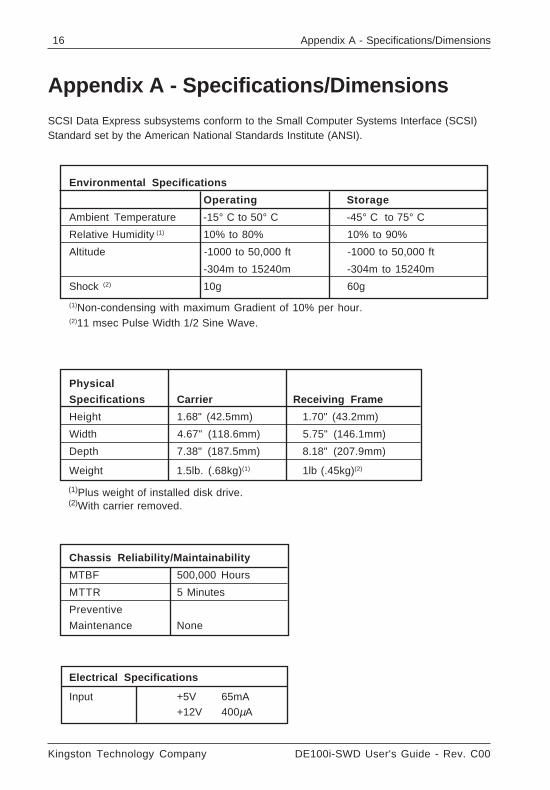
Appendix A - Specifications/Dimensions
Environmental Specifications
Operating Storage
Ambient Temperature -15° C to 50° C -45° C to 75° C
Relative Humidity (1) 10% to 80% 10% to 90%
Altitude -1000 to 50,000 ft -1000 to 50,000 ft
-304m to 15240m -304m to 15240m
Shock (2) 10g 60g
(1)Non-condensing with maximum Gradient of 10% per hour.(2)11 msec Pulse Width 1/2 Sine Wave.
Physical
Specifications Carrier Receiving Frame
Height 1.68" (42.5mm) 1.70" (43.2mm)
Width 4.67" (118.6mm) 5.75" (146.1mm)
Depth 7.38" (187.5mm) 8.18" (207.9mm)
Weight 1.5lb. (.68kg)(1) 1lb (.45kg)(2)
Chassis Reliability/Maintainability
MTBF 500,000 Hours
MTTR 5 Minutes
Preventive
Maintenance None
Electrical Specifications
Input +5V 65mA+12V 400µA
(1)Plus weight of installed disk drive.(2)With carrier removed.
SCSI Data Express subsystems conform to the Small Computer Systems Interface (SCSI)Standard set by the American National Standards Institute (ANSI).
DE100i-SWD User's Guide - Rev. C00 Kingston Technology Company
Appendix A - Specifications/Dimensions 17
1.70 (43.2)
5.875(149.2)
2.060(52.3)
3.125(79.4)
.50(12.7)
.375(9.5)
#6-32 x 8
ReceivingFramewith Carrier
CarrierOnly
7.38 (187.5)
.245(6.2)
1.68(42.7)
4.665(118.5)
0285A
8.19 (208.0)
.250(6.4)
.15(3.8)3.125
(79.4)
5.50(139.7)
#6-32 x 4Bottom
1.75(44.5)
3.75 (95.3)
With HotSwapBoardDE100Board
HotSwapBoard
.64(16.3)
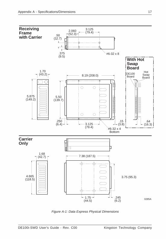
Figure A-1: Data Express Physical Dimensions
Kingston Technology Company DE100i-SWD User's Guide - Rev. C00
18 Appendix B - Factory-Installed Options
Appendix B - Factory-Installed Options
Hot Swap Feature
The DE100 SCSI Hot Swap Board allows the installation, removal or exchange of DataExpress carriers while your computer system is operating by monitoring and protecting thecomputer system and other peripheral devices on the SCSI Bus. The Hot Swap optioneliminates the need to shut down your system when adding or removing a SCSI device byperforming two functions:
1. Delays power up/down of the drive until the time period between SCSI bus cycles.This prevents the interruption of any SCSI bus activity by other devices on the bus.
2. Prevents drive power sequencing from generating noise on the SCSI bus, thuspreventing data transfer corruption on other devices.
Please note that, whereas UNIX and Apple based systems provide mount/dismount drivecommands, most PC systems do not provide such a feature. When using one of theseoperating systems, it may be necessary to reboot the computer after adding or changing adrive. This reboot activity will force the SCSI host adapter to rescan its SCSI bus forphysically attached drives, and will then be able to access the new or changed drive.
Attaching the Hot Swap Board to the DE100i-SWD
The DE100i-SWD may be purchased with the Hot Swap option factory-installed. If the HotSwap Board has not already been attached to the Data Express receiving frame, follow theinstructions below to add the Hot Swap Board:
NOTE: The drive carrier must be installed in the receiving frame when removing orattaching the Hot Swap Board to ensure proper alignment between themotherboard and the disk drive.
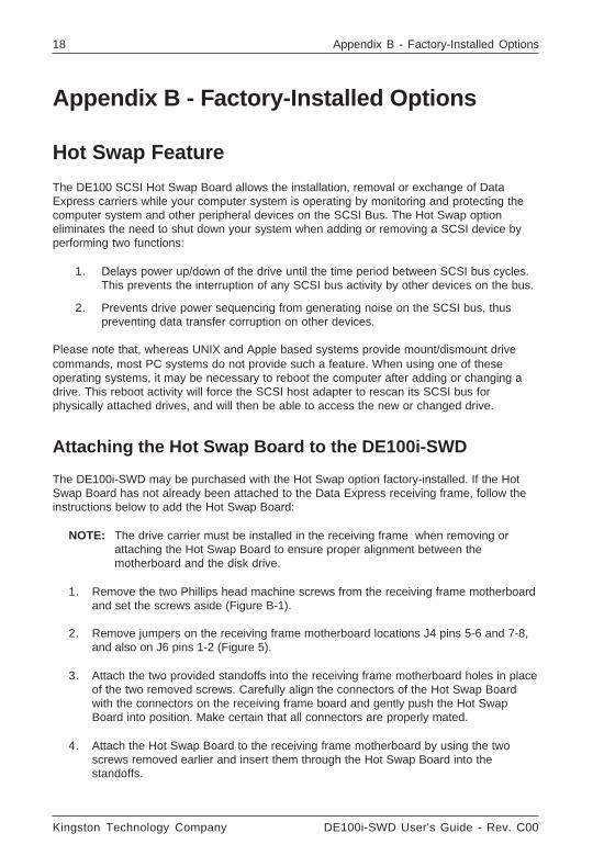
1. Remove the two Phillips head machine screws from the receiving frame motherboardand set the screws aside (Figure B-1).
2. Remove jumpers on the receiving frame motherboard locations J4 pins 5-6 and 7-8,and also on J6 pins 1-2 (Figure 5).
3. Attach the two provided standoffs into the receiving frame motherboard holes in placeof the two removed screws. Carefully align the connectors of the Hot Swap Boardwith the connectors on the receiving frame board and gently push the Hot SwapBoard into position. Make certain that all connectors are properly mated.
4. Attach the Hot Swap Board to the receiving frame motherboard by using the twoscrews removed earlier and insert them through the Hot Swap Board into thestandoffs.
DE100i-SWD User's Guide - Rev. C00 Kingston Technology Company
Appendix B - Factory-Installed Options 19
Figure B-1: Attaching the Hot Swap Board
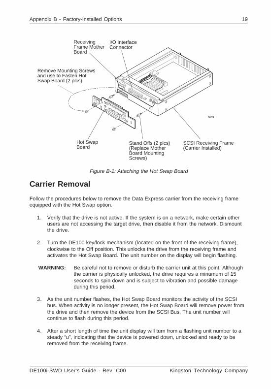
Carrier Removal
Follow the procedures below to remove the Data Express carrier from the receiving frameequipped with the Hot Swap option.
1. Verify that the drive is not active. If the system is on a network, make certain otherusers are not accessing the target drive, then disable it from the network. Dismountthe drive.
2. Turn the DE100 key/lock mechanism (located on the front of the receiving frame),clockwise to the Off position. This unlocks the drive from the receiving frame andactivates the Hot Swap Board. The unit number on the display will begin flashing.
WARNING: Be careful not to remove or disturb the carrier unit at this point. Althoughthe carrier is physically unlocked, the drive requires a minumum of 15seconds to spin down and is subject to vibration and possible damageduring this period.
3. As the unit number flashes, the Hot Swap Board monitors the activity of the SCSIbus. When activity is no longer present, the Hot Swap Board will remove power fromthe drive and then remove the device from the SCSI Bus. The unit number willcontinue to flash during this period.
4. After a short length of time the unit display will turn from a flashing unit number to asteady “u”, indicating that the device is powered down, unlocked and ready to beremoved from the receiving frame.
I/O InterfaceConnector
SCSI Receiving Frame(Carrier Installed)
0639
Hot SwapBoard
ReceivingFrame MotherBoard
Stand Offs (2 plcs)(Replace MotherBoard MountingScrews)
Remove Mounting Screwsand use to Fasten HotSwap Board (2 plcs)
Kingston Technology Company DE100i-SWD User's Guide - Rev. C00
20 Appendix B - Factory-Installed Options
Front ofReceivingFrame
0143B
02
4
68
A
C
E0 = 10 SECONDS 8 = 50 SECONDS1 = 15 SECONDS 9 = 55 SECONDS2 = 20 SECONDS A = 60 SECONDS3 = 25 SECONDS B = 65 SECONDS4 = 30 SECONDS C = 70 SECONDS5 = 35 SECONDS D = 75 SECONDS6 = 40 SECONDS E = 80 SECONDS7 = 45 SECONDS F = 85 SECONDS
Spin Down/Up Time
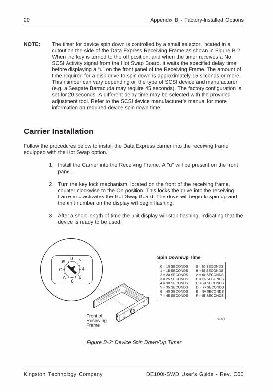
NOTE: The timer for device spin down is controlled by a small selector, located in acutout on the side of the Data Express Receiving Frame as shown in Figure B-2.When the key is turned to the off position, and when the timer receives a NoSCSI Activity signal from the Hot Swap Board, it waits the specified delay timebefore displaying a “u” on the front panel of the Receiving Frame. The amount oftime required for a disk drive to spin down is approximately 15 seconds or more.This number can vary depending on the type of SCSI device and manufacturer(e.g. a Seagate Barracuda may require 45 seconds). The factory configuration isset for 20 seconds. A different delay time may be selected with the providedadjustment tool. Refer to the SCSI device manufacturer’s manual for moreinformation on required device spin down time.
Figure B-2: Device Spin Down/Up Timer
Carrier Installation
Follow the procedures below to install the Data Express carrier into the receiving frameequipped with the Hot Swap option.
1. Install the Carrier into the Receiving Frame. A "u" will be present on the frontpanel.
2. Turn the key lock mechanism, located on the front of the receiving frame,counter clockwise to the On position. This locks the drive into the receivingframe and activates the Hot Swap Board. The drive will begin to spin up andthe unit number on the display will begin flashing.
3. After a short length of time the unit display will stop flashing, indicating that thedevice is ready to be used.
DE100i-SWD User's Guide - Rev. C00 Kingston Technology Company
Appendix B - Factory-Installed Options 21
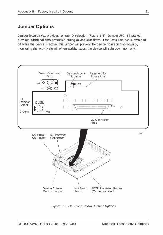
Jumper Options
Jumper location W1 provides remote ID selection (Figure B-3). Jumper JP7, if installed,provides additional data protection during device spin-down. If the Data Express is switchedoff while the device is active, this jumper will prevent the device from spinning-down bymonitoring the activity signal. When activity stops, the device will spin down normally.
Power ConnectorPin 1
IDRemoteSelect
I/O ConnectorPin 1
Ground
ID0
ID1
ID2
J3
+5 +12GND
ID3
P1
W1
JP7
Device ActivityMonitor
Reserved forFuture Use
DC PowerConnector
I/O InterfaceConnector
SCSI Receiving Frame(Carrier Installed)
0637
Hot SwapBoard
Device ActivityMonitor Jumper
Figure B-3: Hot Swap Board Jumper Options
Kingston Technology Company DE100i-SWD User's Guide - Rev. C00
22 Appendix B - Factory-Installed Options
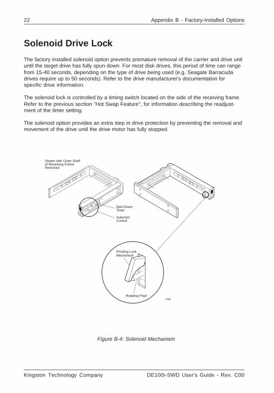
Solenoid Drive Lock
The factory installed solenoid option prevents premature removal of the carrier and drive unituntil the target drive has fully spun down. For most disk drives, this period of time can rangefrom 15-40 seconds, depending on the type of drive being used (e.g. Seagate Barracudadrives require up to 50 seconds). Refer to the drive manufacturer's documentation forspecific drive information.
The solenoid lock is controlled by a timing switch located on the side of the receiving frame.Refer to the previous section "Hot Swap Feature", for information describing the readjust-ment of the timer setting.
The solenoid option provides an extra step in drive protection by preventing the removal andmovement of the drive until the drive motor has fully stopped.
Pivoting LockMechanism
Rotating Pawl0286
SolenoidControl
Spin-DownTimer
Shown with Outer Shellof Receiving FrameRemoved
Figure B-4: Solenoid Mechanism
DE100i-SWD User's Guide - Rev. C00 Kingston Technology Company
Appendix C - Attaching the On/Off Key 23
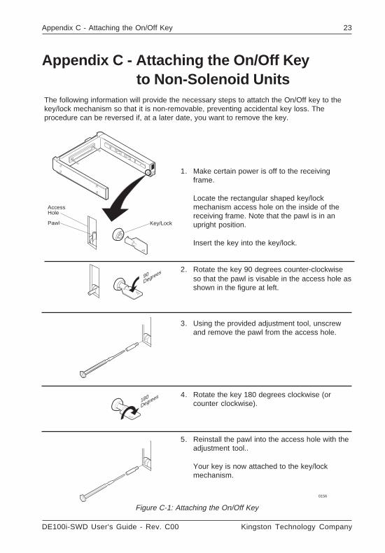
The following information will provide the necessary steps to attatch the On/Off key to thekey/lock mechanism so that it is non-removable, preventing accidental key loss. Theprocedure can be reversed if, at a later date, you want to remove the key.
1. Make certain power is off to the receivingframe.
Locate the rectangular shaped key/lockmechanism access hole on the inside of thereceiving frame. Note that the pawl is in anupright position.
Insert the key into the key/lock.
2. Rotate the key 90 degrees counter-clockwiseso that the pawl is visable in the access hole asshown in the figure at left.
3. Using the provided adjustment tool, unscrewand remove the pawl from the access hole.
4. Rotate the key 180 degrees clockwise (orcounter clockwise).
5. Reinstall the pawl into the access hole with theadjustment tool..
Your key is now attached to the key/lockmechanism.
0156
Pawl
AccessHole
Key/Lock
90Degrees
180
Degrees
Appendix C - Attaching the On/Off Keyto Non-Solenoid Units
Figure C-1: Attaching the On/Off Key
Kingston Technology Company DE100i-SWD User's Guide - Rev. C00
24 Appendix D - Optional Accessories
Appendix D - Optional Accessories
Carrying Case
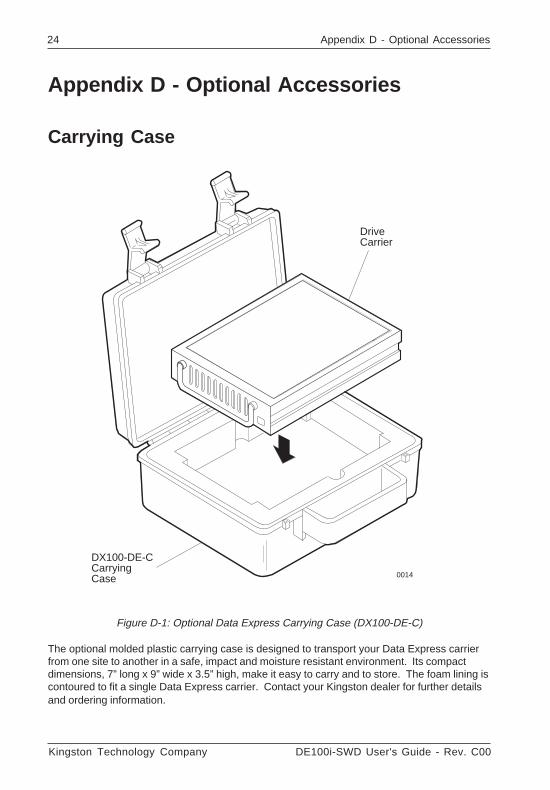
Figure D-1: Optional Data Express Carrying Case (DX100-DE-C)
The optional molded plastic carrying case is designed to transport your Data Express carrierfrom one site to another in a safe, impact and moisture resistant environment. Its compactdimensions, 7” long x 9” wide x 3.5” high, make it easy to carry and to store. The foam lining iscontoured to fit a single Data Express carrier. Contact your Kingston dealer for further detailsand ordering information.
DriveCarrier
DX100-DE-CCarryingCase 0014
DE100i-SWD User's Guide - Rev. C00 Kingston Technology Company
Appendix D - Optional Accessories 25
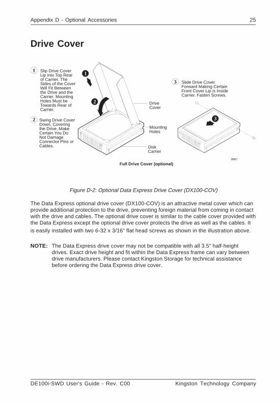
Figure D-2: Optional Data Express Drive Cover (DX100-COV)
The Data Express optional drive cover (DX100-COV) is an attractive metal cover which canprovide additional protection to the drive, preventing foreign material from coming in contactwith the drive and cables. The optional drive cover is similar to the cable cover provided withthe Data Express except the optional drive cover protects the drive as well as the cables. Itis easily installed with two 6-32 x 3/16" flat head screws as shown in the illustration above.
NOTE: The Data Express drive cover may not be compatible with all 3.5" half-heightdrives. Exact drive height and fit within the Data Express frame can vary betweendrive manufacturers. Please contact Kingston Storage for technical assistancebefore ordering the Data Express drive cover.
Slip Drive Cover Lip into Top Rear of Carrier. The Sides of the Cover Will Fit Between the Drive and the Carrier. Mounting Holes Must be Towards Rear of Carrier.
1
Swing Drive Cover Down, Covering the Drive. Make Certain You Do Not Damage Connector Pins or Cables.
2
Slide Drive Cover Forward Making Certain Front Cover Lip is Inside Carrier. Fasten Screws.
3
Full Drive Cover (optional)
Disk Carrier
Drive Cover
Mounting Holes
1
2
3
0067
Drive Cover
Kingston Technology Company DE100i-SWD User's Guide - Rev. C00
26 Appendix D - Optional Accessories
Write Protect Switch
WRITE PROTECT
OFF
ON
WRITE PROTECT
OFF
ON
0357A
Disk Carrier
Disk Drive Write ProtectSwitch Bracket and CableCover
Write ProtectConnector(attach to appropriatedisk drive pins)
(Disk Drive notshown for clarity)
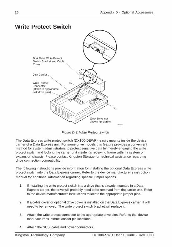
Figure D-3: Write Protect Switch
The Data Express write protect switch (DX100-DEWP), easily mounts inside the devicecarrier of a Data Express unit. For some drive models this feature provides a convenientmethod for system administrators to protect sensitive data by merely engaging the writeprotect switch and locking the carrier unit inside it's receiving frame within a system orexpansion chassis. Please contact Kingston Storage for technical assistance regardingdrive connection compatibility.
The following instructions provide information for installing the optional Data Express writeprotect switch into the Data Express carrier. Refer to the device manufacturer's instructionmanual for additional information regarding specific jumper options.
1. If installing the write protect switch into a drive that is already mounted in a DataExpress carrier, the drive will probably need to be removed from the carrier unit. Referto the device manufacturer's instructions to locate the appropriate jumper pins.
2. If a cable cover or optional drive cover is installed on the Data Express carrier, it willneed to be removed. The write protect switch bracket will replace it.
3. Attach the write protect connector to the appropriate drive pins. Refer to the devicemanufacturer's instructions for pin locations.
4. Attach the SCSI cable and power connectors.
DE100i-SWD User's Guide - Rev. C00 Kingston Technology Company
Appendix D - Optional Accessories 27
Drive Plug
0429
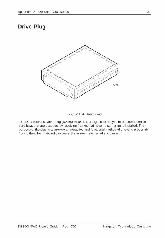
Figure D-4: Drive Plug
The Data Express Drive Plug (DX100-PLUG), is designed to fill system or external enclo-sure bays that are occupied by receiving frames that have no carrier units installed. Thepurpose of the plug is to provide an attractive and functional method of directing proper airflow to the other installed devices in the system or external enclosure.


![Shoku no Miyako - c00 [batoto]](https://img.dokumen.tips/doc/110x75/613ca8ac9cc893456e1e92ac/shoku-no-miyako-c00-batoto.jpg)

