Embed Size (px)
Citation preview


Nutec flat sheets are manufactured from a combination of Portland cement, silica and organic fibres,and do not contain any asbestos fibres. These materials have considerable strength in their own right
and will not deteriorate with age.
EVERITE has over the years established a reputation for producing outstanding quality
flat sheets which have been used in a wide range of external and internal applications.
In the late eighties and after extensive research, EVERITE launched its range of Nutec flat
sheets, the registered name for products manufactured without asbestos as a raw material.
This development has resulted in innovative new products which not only have similar characteristics
to fibre-cement flat sheets, but are superior in many ways.
Nutec flat sheets are available in medium and high density material and in plain
and medium density textured finishes, offering a wider choice for innovative applications.
As a partition board, it offers major advantages over conventional materials in terms of strength and
resistance to biological attack.
In summary Nutec flat sheets are:
• An economical all-purpose building board which is unaffected by moisture and therefore
ideal for internal and external use in almost any application.
• Relatively light in weight and can be supported on light gauge metal frames or light timber
structures. These factors facilitate easy handling and erection and are major benefits on
projects where low mass construction is an important factor.
• Non combustible and provide perfect protection against flying sparks.
• Resistant to corrosion and are unaffected by ultraviolet light.
• Designed to have good thermal properties when compared with other building materials.
• Manufactured to the highest internal quality standards and compliance is ensured by strict
quality assurance programmes in the production process as well as stringent testing in our
laboratory. All Nutec Flat sheets carry a SABS mark for compliance to the specification
SANS 803. Nutec flat sheets are supplied in their natural colour, but are compatible with a
large variety of in-situ applied coatings and paints. This will allow the designer an almost
limitless combination of colours and textures for external and internal applications.
The sheets are best painted with a pure acrylic PVA paint. Where it is intended to use oil or alkyd
paints it is essential to prime the sheet with an alkali-resistant sealer. In this instance both faces
of the product should be sealed.
Use only high density sheets for external flat sheet facades where the surface is to be painted.
Introduction 1
Flat Sheets & Facades 2009

General Design Criteria .............................................................................................................................. 3
Nutec Mechanical and Physical Properties ............................................................................................. 5
Nutec Mechanical and Physical Properties ............................................................................................. 6
Fire Resistance - Floor/ceiling Systems....................................................................................................... 7
Fire Resistance - Nutec Boards in Wall Systems ........................................................................................ 8
Acoustical Insulation ................................................................................................................................... 9
Handling and Storage............................................................................................................................... 10
General Installation Guidelines ................................................................................................................ 11
Product Range .......................................................................................................................................... 12
Application Possibilities
• Recommended Uses of Nutec flat sheets ........................................................................................ 13
Fixing Details
• Special Fascia Boards ......................................................................................................................... 14
• Timber and Steel Framework.............................................................................................................. 15
• Flush Jointing ........................................................................................................................................ 18
• Wall Tiling............................................................................................................................................... 19
• Nutec Sheets in Shuttering Applications ........................................................................................... 21
• Access Floor System ............................................................................................................................ 22
General Information Facades and Cladding ........................................................................................ 23
Accessories................................................................................................................................................. 24
Fixing Details ............................................................................................................................................... 25
Jointing Systems ......................................................................................................................................... 29
General information on Tongue & Groove Board ................................................................................. 35
Bill of Quantities.......................................................................................................................................... 39
Company - Contact Details ..................................................................................................................... 40
Index 2
Flat Sheets & Facades 2009

Catalogue InformationThe information contained in this catalogue serves as a general guide only and should not be
accepted as the standard for all construction. Consult EVERITE for designs of a special nature.
This service is provided free of charge and without obligation, but architects, engineers and
specifiers must finally approve the acceptability in terms of the design and construction criteria,
as well as other implications.
Mechanical and Physical PropertiesFor details on the mechanical and physical properties of Nutec flat sheets, refer to
Table 2, Page 5 and 6.
Recommended UsesThe recommended uses of Nutec flat sheets under normal conditions are tabulated for easy reference
in Table 3, Page 13.
Exposed and Windy ConditionsThe information presented in this catalogue is relevant for normal wind-loading conditions.
EVERITE should be consulted for advice on specific fixing and framing recommendations where structuresare situated in high wind areas.
SubstructureThe design of structural supports requires professional expertise and should, as a general rule,
be executed by structural engineers. Minimum design parameters are that the structure should
be able to withstand 1,2 kPa wind loadings. (Structures not higher than 6 metres.)
TABLE 1 Recommended Supporting Structure for Nutec Flat SheetsExternal and Internal Vertical Cladding
Description and Thickness Maximum spans between Maximum spans betweenof Board - mm vertical supports - mm horizontal supports - mmMedium density
9 600 80012 600 900
High density10 600 80015 800 1 200
NB: • The information presented in the above table is relevant for wind-loading conditions normallyencountered and for structures not higher than 6m.
• For higher structures and for areas where design wind pressure exceeds 1,5 kPa, a structuralengineer should be consulted.
• Consult EVERITE for specific fixing and framing recommendations where the sheets are to beused for applications such as floors, shelving and permanent shuttering.
• If used for flooring, and covered by ceramic tiles or other inflexible material, expansion jointsmust be provided. Refer to EVERITE sales office technical department.
• Using 9mm and 12mm M.D. externally, coating in a smooth acrylic paint is recommended.
General Design Criteria 3
Flat Sheets & Facades 2009
VentilationWhen using Nutec flat sheets to form a double skin wall in a prefabricated steel or timber framed
structure, the cavity between the two skins should be ventilated. In these structures, especially
in humid conditions, foil is often installed as a moisture barrier and as an insulator. Ventilating
the cavity will permit the evaporation of any condensation which may collect on the
insulating material.
Site ServiceSite service personnel are available on request to assist with recommended storage, handling
and erection of the Company’s products before and during installation.
General Design Criteria 4
Flat Sheets & Facades 2009

TABLE 2 Mechanical and Physical Properties
Nutec Mechanicaland Physical Properties 5
SPECIFICATIONS
TYPICAL VALUES
PARAMETER
DIMENSIONSThickness Tolerance:9 mm
10 mm
12mm
15 mm
Length Tolerance:All lengths
Width Tolerance:All widths
SquarenessAll sizes
Edge TruenessAll sizes
PHYSICAL PROPERTIESMinimum MOR : With GrainMinimum MOR : Across GrainTarget DensityMaximum Hygral Linear Expansion
Thermal ConductivityThermal Expansion Coefficient20-70˚C
10-70˚C
Moisture MovementWith Grain
Across Grain
Moisture ContentWater AbsorptionPermeability
Water Vapour TransmissionpHMECHANICAL PROPERTIESMOR : With GrainMOR : Across Grain
UNIT
mm
mm
mm
mm
mm
mm
mm
mm
MPa
MPa
g/cm3
mm/m
W/m.K
˚C-1
˚C-1
%
%
%
%
-
ng/Pa.s.m2
-
MPa
MPa
MPa
MPa
MPa
MPa
HighDensity
-
± 0.8
-
± 1.0
± 2
± 2
Maximum 5
Maximum 1
9.00 (2)
13.00 (2)
1.50
2.47
0.30
Negligible
4.21 x 10⁻⁶
0.30
0.06
6.92
22.05
No droplets
formed
97.154
10 – 12
-
14.40 (3)
-
-
24.05 (3)
-
Semi-HighDensity
+ 0.3 or - 0.3
-
± 0.8
-
+0 or -5
+0 or -2
Maximum 2
Maximum 3
8.44 (1)
12.10 (1)
1.35
2.47
-
-
-
0.053
0.049
2.53
28.10
No droplets
formed
-
10 – 12
6.20 (2)
11.20 (3)
9.40 (3)
8.40 (2)
18.50 (3)
15.60 (3)
MediumDensity
± 0.8
-
-
-
+3 or -5
+3 or -5
Maximum 5
Maximum 5
7.40 (1)
10.60 (1)
1.26
2.47
0.19
Negligible
9.31 x 10⁻⁶
0.06
0.06
6.25
37.72
No droplets
formed
276.79
10 – 12
4.20 (2)
7.50 (3)
11.20 (3)
7.75 (2)
12.10 (3)
16.40 (3)
Textured Nutec
± 0.8
-
-
+3 or -5
+3 or -5
Maximum 5
Maximum 5
7.40 (1)
10.60 (1)
1.26
2.47
0.19
Negligible
9.31 x 10⁻⁶
0.06
0.06
6.25
37.72
No droplets
formed
276.79
10 – 12
4.20 (2)
7.50 (3)
11.20 (3)
7.75 (2)
12.10 (3)
16.40 (3)
TEST METHOD
SANS 803
SANS 803
SANS 803
SANS 803
SANS 803
SANS 803
SANS 803
SANS 803 – 1995
SANS 803 – 1995
ISO 8336-1993
SANS 803 – 1995
ASTM C518
SANS Doc. 722/W 1009
ASTM C518
ASTM C1185
ASTM C1185
ASTM C1185
ASTM C1185
SANS 685 – 1985
ASTM C1185
BS 4624
ASTM E96
-
ASTM C1185
ASTM C1185
BS 4624
ASTM C1185
ASTM C1185
BS 4624
Flat Sheets & Facades 2009

TABLE 2
Nutec Mechanicaland Physical Properties 6
PARAMETER
Classification in accordanceto ASTM C1186Compressive Strength Parallel toSurface of BoardWith Grain
Across Grain
Tensile Strength Parallel toSurface of BoardWith Grain
Across Grain
Tensile Strength Parallel toSurface of BoardYoung’s Modulus (E.Mod)With Grain
Across Grain
Block Shear Strength
FIRE PROPERTIESSurface Spread of Flame
Spread of Flame Index
Heat Contribution Index
Smoke Emission Index
Surface Fire Index
Surface Burning CharacteristicsFSI (Flame spread index)
SD (Smoke developed index)
Non-CombustibilityContinuous TemperatureOTHER PROPERTIESFrost ResistanceCycles Completed
Strength Ratio
Biological ResistanceRodent Resistance
Termite Resistance
Resistance to Bacteria
UNIT
-
MPa
MPa
MPa
MPa
MPa
MPa
MPa
MPa
MPa
MPa
MPa
MPa
MPa
MPa
MPa
MPa
Class
-
-
-
-
-
-
-
-
%
Class
HighDensity
l l
15.21
24.62
20.61
37.22 3(3)
3.47 (2)
5.12 (3)
4.34 (2)
5.95 (3)
1.42 (2)
2.18 (3)
9898 (3)
7747 (2)
11645 (3)
7903 (2)
3.30 (3)
3.17 (2)
1
Nil
Nil
Nil
Nil
0
5
Non-combus.
150˚C
50
97.5
B1
No Damage
-
Semi-HighDensity
l
-
-
-
-
-
-
-
-
-
-
-
-
-
-
-
-
1
Nil
Nil
Nil
Nil
-
-
Non-combus.
150˚C
-
-
-
-
-
MediumDensity
I
10.86 (2)
15.57 (3)
11.54 (2)
19.58 (3)
2.11 (2)
3.26 (3)
2.24 (2)
2.88 (3)
0.83 (2)
1.02 (3)
5337 (3)
3974 (2)
6474 (3)
4681 (2)
1.60 (2)
1.32 (3)
1
Nil
Nil
Nil
Nil
0
3
Non-combus.
150˚C
50
78.5
B1
No Damage
No Growth
Textured Nutec
l
-
-
-
-
-
-
-
-
-
-
-
-
-
-
-
-
1
Nil
Nil
Nil
Nil
0
3
Non-combus.
150˚C
-
-
-
-
-
TEST METHOD
ASTM C1186
ASTM D1037
ASTM D1037
ASTM D1037
ASTM D1037
ASTM D1037
ASTM D1037
ASTM D1037
ASTM D1037
ASTM D1037
ASTM D1037
ASTM C120
ASTM C120
ASTM C120
ASTM C120
ASTM D143
ASTM D143
SANS 10177: Part 111, BS 476:
Part 7
SANS 10177 Part III
SANS 10177 Part III
SANS 10177 Part III
SANS 10177 Part III
ASTM E84
ASTM E 84
BS 476 Part 4, SANS 10177: Part V
-
ASTM C1185
ASTM C1185
SANS 5417
SANS 5471
BS 5980: 1980
(1) Dried till constant weight(2) Saturated with water(3) Equilibrium conditions
Flat Sheets & Facades 2009

FIG. General Plan of Arrangement of Floor/Ceiling 60 Minute Fire Rated System - Loading 1500 kN/m2
1. Softwood timber joists - 230mm x 50mm at 600mm centre.
2. Floor Boards HD Nutec, 3600mm x 1200mm x 15mm.
3. Softwood timber noggings at 600mm centres by means of 100mm nails.
4. 50mm timber screws at 300mm centres.
5. Mineral Fibre seal.
6. 6mm Nutec Ceiling Board, 3600mm x 1200mm. Fixed with 50mm timber screws at 300mm centres
to underside.
Insulation: 50mm Insulmate, 80 kg/m3.
Joints sealed with Intumex MA.
Screws and nail heads sealed with sodium silicate liquid.
Fire Resistance- Floor/Ceiling Systems 7
575 600 600 600 600 575
1
5
6
3
4
2
Flat Sheets & Facades 2009

Fire Rating Timber Frame Systems Galvanised Steel Stud Systems
20 minutes
20 minutes
27 minutes
30 minutes
33 minutes
41 minutes
60 minutes
120 minutes
Fire Resistance- Nutec Boards in Wall Systems 8
600mm 30mm
4mm MD NutecSisalation 400
70mm
600mm 30mm
70mm
Sisalation 4006mm MD Nutec
600mm
64mm
65mm Drywall studs9mm MD Nutec
600mm 30mm
70mm
Sisalation 4009mm MD Nutec
600mm
9mm MD Nutec 65mm Drywall studs
64mm
600mm 50mm
63mm
9mm MD Nutec50mm Mineral wool, density: 24 kg/m3
65mm Drywall studs
64mm
12mm MD Nutec
600mm
600mm
64mm
65mm Drywall studsLight weight concrete fill
9mm Mediumdensity Flat Sheets
Face layer joints to be taped and plastered.Drywall screws spaced at +/- 250mm centres.All fixings according to Everite Building Products’ recommendations Flat Sheets & Facades 2009

Rw - value (dB) Nutec
26.0 dB
35.7 dB
38.0 dB
40.0 dB
44.8 dB
45.7dB
47.2dB 51mm
51mm Drywall studs40mm Aerolite6mm MD Nutec
600mm
51mm
600mm
51mm Drywall studs40mm Aerolite6mm MD Nutec
1200mm
51mm
51mm Drywall studs6mm MD Nutec
40mm Aerolite
400mm
52mm
9mm MD Nutec52mm Drywall studs
400mm
52mm
52mm Drywall studs7.5mm MD Nutec
1200mm
51mm
51mm Drywall studs6mm MD Nutec
4mm MD Nutec
Acoustical Insulation 9
52mm Drywall studs
Flat Sheets & Facades 2009

Nutec flat sheets are manufactured from a composite material containing mainly cement and
may be damaged under excessively high shock loads. Reasonable care should therefore be
taken to ensure that the products are not dropped or subjected to rough handling.
While stacked, Nutec flat sheets should not be exposed to the elements for lengthy periods and
under cover storage is recommended.
A smooth level under cover area should therefore be made available where the sheets can be
stacked safely. The stacks should be supported on suitable timber bearers at maximum 400mm
centres and the edges and corners protected against possible damage.
Where under cover storage is not available, the stacked product should be covered to avoid it
becoming soaked with water. Soaked sheets will be difficult to handle and should be allowed to
dry out before use.
It is recommended that sheets should not be stored for a period exceeding one monthif not under cover.
Handling and Storage 10
Flat Sheets & Facades 2009

• Nutec flat sheets as manufactured are made without asbestos fibres, it is nevertheless recommended
that when working with the product, tools that create excessive dust should not be used.
Ordinary carpenters’ tools can be used effectively.
For further information refer to the brochure ‘Finishing and Maintenance’.
• To ensure a high standard of finish, it is essential that the supporting structure is accurately constructed.Warped, twisted or poor quality timber, or badly erected steelwork will reflect in the finished surfaceand can cause damage to the product.
The structure must be checked and adjusted as necessary to ensure that there is no bowing
or distortion which could affect the true plane of the final application.
• For maximum spacings between supports for Nutec flat sheets, refer Table 1 page 3 andFig. 8 page 26 and Fig. 9 page 27.
Sheets should not be fixed directly onto a masonry wall, but on timber or steel battens
forming a framework to which the fascia boards or sheets can be fixed.
• Holes for fixing must be set out evenly and must be drilled and not punched.
An ordinary hand drill and steel drill bits specially sharpened to a 20° angle are recommended.
The drill bit must be 2mm larger than the diameter of the fixing bolt or screw.
• When the sheets are fixed into a framed structure allowance must be made for thermal
movements in the sheet and the supporting structure.
The allowance for movement will depend on the size of the sheet, but an average can be acceptedas ± 2mm per metre in both directions. For facade jointing, use recommended jointing details.
General Installation Guidelines 11
Flat Sheets & Facades 2009

NUTEC FLAT SHEETSMD = Medium DensityHD = High Density
Product No. Nominal Thickness Size Average Massmm mm kg
010-910 9 MD 2 400 x 1 200 38
010-911 9 MD 3 000 x 1 200 47
010 -912 9 MD 3 600 x 1 200 52
011-210 12 MD 2 400 x 1 200 49
011-211 12 MD 3 000 x 1 200 61
011-212 12 MD 3 600 x 1 200 73
011-005 10 HD 3 000 x 1 200 61
011-006 10 HD 3 600 x 1 200 73
011-505 15 HD 3 000 x 1 200 87
011-506 15 HD 3 600 x 1 200 104
Textured Tongue & Groove Boards used for internal cladding only
650-567 6 MD 1 200 x 2 400 24
650-568 6 MD 1 200 x 3 000 30
650-569 6 MD 1 200 x 3 600 37
060-643 9 MD 1 200 x 2 400 35
060-644 9 MD 1 200 x 3 000 44
060-645 9 MD 1 200 x 3 600 52
Plain Tongue & Groove Boards used for internal cladding only
650-566 6 MD 1 200 x 3 000 30
Floor Boards
011-504 15HD Floor Board 1 800 x 1 200 52
Product Range 12
Flat Sheets & Facades 2009

TABLE 3 Recommended Uses of Nutec Flat Sheets
Medium Density High Density
ProductDescription
Internal panelling
Gable cladding
Prefabricated housing
Steel & Timber frame houses & steel frame interior walls
Steel & Timber frame houses & steel frame exterior walls
Partitioning
Sandwich panels
Special size fascias
Louvres
Balustrading
Steel beam and column lining
Cable trench covers
Permanent shuttering
Toilet and shower partitioning
Floors
Special size windowsills
External facades (stone chip finish)
External facades (paint application)
Suspended floors
Application 13Re
comm
ende
d Use
s
Plain
9mm
Plain
12mm
Textur
ed 6m
m
Textur
ed 9m
m
Plain
10mm
Plain
15mm
Flat Sheets & Facades 2009

Special Fascia BoardsFIG. 1 Using Nutec Flat Sheets as a Special Fascia
NB: • In the above application 9mm medium density sheets are used. In instances where ceramictiles are fixed to a fascia, minimum thickness of sheets should be 10mm high density or 12 mmmedium density sheets.
• The flashing should be sloped away from the face of the fascia to avoid discolouration due todust being washed down by rain over the finished surface.
• For spanning capabilities of FLAT SHEETS, refer Table 1, Page 3.
• Fascias should not be fixed directly to a wall, use timber battens to provide a framework for thefascia.
Fixing Details 14
1 Nutec Flat sheet
2 Timber support structure
3 Intermediate timber support
4 Battens between timber frames
5 Overhang to form drip
6 Nutec sheets as under eaves lining/soffit
7 Quadrant
8 Wall
9 Galvanized metal flashing
10 Gutter
11 Roofing sheet
12 Purlin
13 Timber truss
14 WallplateAll dimensions in mm
Flat Sheets & Facades 2009

Typical Layout of Sheet on Timber and Steel Framework
NB: • Timber or steel framing may be used and should be constructed in accordance with localbuilding regulations and acceptable building practice.
• Timber should be selected structural grade timber.• Timber supports must be firmly secured to top and bottom plates and frames must not rely on
the Nutec sheets for stability.• Support spacings for external or internal walls should not exceed 600mm centres.• Framing members, should be arranged to support all sheet edges.• Where the support faces behind sheet joints are less than 38mm wide, pack out to provide
additional landing for sheet fixing. Refer fig 4, Page 20.• For further information on timber framed structures, refer to SANS 10082.
Fixing Details 15
Flat Sheets & Facades 2009

2
3
5
6
1
2
3
4
1
2
3
1
2
3
4
Fixing of Sheets to Support
Fixing of Sheet to Narrow Support
JointingThere are various methods that can be used for jointing.
Showing the Use of an H-profile Strip
Fixing Details (cont.) 16
1 Timber stud
2 Galvanised nail or wood screw
3 Nutec sheet
1 Nutec sheet
2 Galvanised nail or wood screw
3 Packing as required for narrow stud
4 Narrow stud
1 Galvanised nailor wood screw
2 H profile jointingstrip
3 Nutec-cementflat sheet
4 Timber stud
5 Fixing screw
6 Metal frame
Flat Sheets & Facades 2009

1
2
3
4
1
2
5
6
21
5
6
2
6
5
12
5
6
Jointing (cont.)Showing Mouldings Used as Cover Strips
Illustrating the Use of Epoxy Fillers for Jointing
JOINTING ON A STRAIGHT WALL
EXTERNAL CORNER JOINT
INTERNAL CORNER JOINT
Fixing Details (cont.) 17
1 Timber moulding
2 Nutec-cement flatsheet
3 Timber stud
4 Galvanised nail orwood screw
5 Fixing screw
6 Metal frame
1 Epoxy filler
2 Nutec sheet
3 Screw fixing
4 Metal frame
5 Galvanised nail orwood screw
6 Timber stud
12
5
6
1
2
3
4
Flat Sheets & Facades 2009

Typical Flush Jointing ApplicationEverite should be consulted for advice on specific application and recommended compounds to
be used.
For flush jointing of Nutec sheets, whether erected on steel studs or timber studs, the procedure
is as follows:
• Prepare jointing compound as per manufacturer’s instructions.
• A suitable plaster is recommended.
• Apply the mixture firmly into the joints between the edges of the board.
• To avoid premature drying out of the mixture do not fill joints longer than 5m at a time.
• Embed ‘Fibatape’ into the mixture using a spatula or plastering trowel and allow to dry
thoroughly. Refer Fig. 2.• Appy a coat of the mixture to nail or screw heads and allow to dry.
• After the base coat has thoroughly dried out apply further coats, allowing each coat to
dry before the next coat is applied.
• Care should be taken to feather out each application so that a smooth joint results.
The final coat is finished off by using a fine grit sand paper.
• For internal corners use ‘Fibatape’ and for external corners use a metal ‘Corner Bead’.
Refer Fig. 2 and apply jointing compound as described above.
FIG. 2 Flushing Jointing Application
Fixing Details (cont.) 18
1 Nutec sheet
2 Edge of board
3 Fixings
4 Fibatape
5 Joint between boards base coat
6 Second coat
7 Final coat
Flat Sheets & Facades 2009

Wall TilingWhere a partition wall is finished with ceramic wall tiles, the following procedures should
be followed:
• Reduce the stud spacing to a maximum of 400 mm.• Provide horizontal noggings between studs at 900 mm centres.
• External and internal corner studs must be joined together using a corner bead.
• Sealed both sides of the Nutec sheet with a concrete sealer.
• Before fixing tiles ensure that the boards are completely free of dust or grease.
• Using a notched trowel apply suitable tile adhesive to the partition board covering an
area of 1m2 at a time.
• Press tile firmly into the adhesive to ensure that no voids occur under the tiles.
• Allow a minimum gap of 2mm between tiles for grouting.
• Directions for mixing of adhesive and grout should be obtained from the manufacturers.
• For bath, shower/wall junction detail refer to Figs. 3, 4 and 5, Pages 19 and 20.
FIG. 3 Bath/Wall Junction Detail Using Steel Frame
Fixing Details (cont.) 19
1 Ceramic wall tiles
2 Nutec sheet
3 Sealant
4 Support angle pop-riveted to stud
5 Galvanised stud
6 Profile of bath
Flat Sheets & Facades 2009

9
1
3
2
5
4
6
78
FIG. 4 Shower Base/Wall Junction Detail Showing Steel Frame
FIG. 5 Base/Wall Junction detail using timber framing
Fixing Details (cont.) 20
1 Nutec sheet
2 Ceramic tiles
3 Steel nogging
4 Galvanised stud
5 Sealant
6 Profile of shower base
7 Track
8 Screen bedding
9 Nutec sheet
1 Timber stud
2 Nutec sheet
3 Ceramic sheet
4 Backing nogging
5 Sealant
6 Fixing point
7 Timber rail to secure rim of bath
8 Timber spacer
9 Base plate
10 Concrete floor slab
11 Nutec sheet
12 Bath
1
2
3
4
5
6
7
8
12
11
9
10
Flat Sheets & Facades 2009

Nutec Sheets in Shuttering Applications
Fixing Details (cont.) 21
1. In 1200 widths
2. Shuttering to have 25mm Minimum bearing at each end
3. Concrete must be spread evenly to avoid excessive heaping
200190018017016015014013012011010090080070600500400300200100
50mm Concrete
400mm Concrete
350mm Concrete
300mm Concrete
250mm Concrete
200mm Concrete
150mm Concrete
100mm Concrete
1,0
2,0
3,0
4,0
5,0
6,0
7,0
8,0
9,0
10,
Un
ifo
rmly
dis
trib
ute
d lo
ad
(kN
/S.S
M.)
Clear span between supports (mm)
15mm High Density
Flat Sheet
10mm High Density
Flat Sheet
10mm Medium Density
Flat Sheet
20mm HD Flat Sheet
Flat Sheets & Facades 2009

Typical Structure for Suspended Floor on steel supports
Typical Loads and Deflection Measured per Floor Board
Temp. RH Deflection Maximum Load GeneralSample No. oC % at 3kN Loading Achieved Remarks
(mm) (kN)1 21,9 45 2,23 4,99
2 21,9 45 2,34 5,39 Ambient
3 21,9 45 2,57 5,13
4 20 65 3,40 5,2948 hour
5 20 65 3,18 5,27 conditioned
6 20 65 3,42 5,72samples
Access Floor System 22
600 x 600 x 15mmHD Nutec Board
Unsupported Area(570 x 570)
Steel Grid
Flat Sheets & Facades 2009

ApplicationEVERITE Nutec sheets and moulded panels are particularly suitable where a light weight and durable
cladding is required. They protect the structure, yet provide access to the many services which are
required in modern buildings. An existing building can be given an entirely new facade without
major alteration to its structural framework.
The availability of in situ coated surfaces presents the designer with an almost limitless
combination of colour and texture.
Quality StandardsEVERITE sheets and moulded panels are manufactured to the requirements of ISO 9001:2000. Flat
sheets carry an SABS mark under specification SANS 803.
FireNutec sheets are non-combustible and do not contribute to the spread of flame.
Thermal InsulationThe thermal properties of Nutec sheets and moulded panels compare very well with other building
materials available on the market. For thermal conductivity values (K value), refer to the table 2:Mechanical and Physical Properties, page 5.
Corrosion ResistanceNutec sheets and moulded panels are resistant to most corrosive conditions encountered in
the environment and is unaffected by ultraviolet light. For further information, consult any
EVERITE Sales Office.
Fixing AccessoriesSuitable fixing accessories are obtainable from EVERITE.
General Information Facadesand Cladding 23
Flat Sheets & Facades 2009

External Facade and Moulded Panel Fixing Accessories*All products not supplied by EVERITE
Fixings FacadeMoulded Panels
Fastener Steel Structure Timber StructureFlat Sheet Flat Sheet Flat Sheet Flat Sheet Fixed to Fixed to
Exposed Concealed Exposed Concealed Steel Timber
Fixing Fixing Fixing Fixing
* Countersunk Head
Brass Wood Screw
40mm x 12mm
* Self Tapping Screw
Countersunk Head
35mm x 5,5mm
* Drill Screw
Countersunk Head
30mm x 5,5mm
* Spade Point Screw
Hexagon Washer Head
50mm x 5,5mm
Steel
Stainless Steel
* Drill Screw
Hexagon Washer Head
50mm x 5,5mm
Steel
Self Tapping Stainless Steel
EPDM GasketsSketch Product No Description Size
602-001 EPDM sealing gasket for use with flat 50mm wide
sheets having open joints
602-002 EPDM sealing gasket for use with flat 80mm wide
sheets having open joints
630-100 Elibond FR964 Epoxy Kit 400 g
630-110 Elibond FR964 Epoxy Kit 1 kg
Silicone Sealer
Galvanised Hoop Iron 50mm x 0,5mm
Foam Backing Strip
All dimensions in mm Fixings
Accessories 24
Flat Sheets & Facades 2009

Setting Out and Fixing Procedures for Nutec Sheet FacadeFor vertical runners or counter battens, cold rolled steel sections could also be used instead of
timber as illustrated in Fig. 7.
• Girts should be provided with elongated holes for fixing to supporting cleats - refer to Fig. 7. This provides for adjustment of the girts to obtain a true fixing line for the panels.
• A basic framing layout is shown in Fig. 8 page 26 and Fig. 9 page 27 for flat sheets.
FIG. 6 FIG. 7
Fixing Details 25
- Holes can be elongated to allow
for adjustment
- Dimension of supporting structure
to be confirmed by engineer
- Dimension of supporting structure
to be confirmed by engineer
All dimensions in mm All dimensions in mm
Flat Sheets & Facades 2009

Setting Out and Fixing Procedures Nutec Sheet Facade (Continued)
• It is recommended that joints in each line of girts occur at the same column or
supporting member.
• A minimum of 75 mm wide bearing surface required behind a horizontal joint to provide
sufficient landing for screws to be placed at least 20 mm from the edge of the panels,
Fig. 8 and 9, page 26 and page 27 for flat sheets.
FIG. 8 Horizontal Girts (See Fig. 9 page 27 for Vertical Runners)
Fixing Details (cont.) 26
All dimensions in mm
Flat Sheets & Facades 2009

20 minimum
600 maximum 600 maximum
20 m
inim
um
Setting Out and Fixing Procedures Nutec Sheet Facade (Continued)• The runners supporting the facades should not exceed 600 mm centres vertically and
800 mm centres horizontally. Framing members should be arranged to support all panel edges,Refer Fig. 8 page 26 and Fig. 9 page 27.
FIG. 9 Vertical runners
NB: • For further design information or copy of the report on wind resistance tests performed by theCSIR, contact EVERITE Sales Office.
• The above is relevant for wind loading conditions for structures not higher than 15m.
Fixing Details (cont.) 27
All dimensions in mm
Flat Sheets & Facades 2009

Setting Out and Fixing Proceduresof Nutec Sheets
FIG. 10 Framing Behind Horizontal Joints / Vertical Joints
FIG. 11 Counter Screw Detail
Fixing Details (cont.) 28
All dimensions in mm
1 In situ coating as required
2 Moulded panel
3 Steel support rail
4 Countersunk self tapping screw
5 Epoxy filler sanded flush with panel
6 2mm oversize hole
Flat Sheets & Facades 2009

NUTEC SHEET FACADEOpen JointsFor open vertical, horizontal and corner joints, EPDM gaskets are recommended. As an extra
precaution against water penetration, silicone is used in conjunction with the EPDM gasket -
Fig. 12(A) and Fig. 12(B) page 29, Fig.13(A) and Fig. 13(B) page 30, Fig. 14(A) and Fig. 14(B) Page 31.
For alternative horizontal joints, silicone is used. Fig.10 page 28 and alternative Fig.15, page 32.
FIG. 12(A) Perspective of an Open Vertical Joint
FIG. 12(B) Plan of an Open Vertical Joint
Jointing Systems 29
All dimensions in mm
1 Timber/steel framefixed to main structure
2 50/80mm EPDM gasketfixed
3 Silicone bead
4 10mm open joint
5 Nutec sheet
6 Outer line of mainstructure
4 10mm open joint
5 Nutec sheet
6 Outer line of main structure
All dimensions in mm
1 Timber/steel frame fixed to main structure
2 50/80mm EPDM gasket fixed to frame
3 Silicone bead
Flat Sheets & Facades 2009
NUTEC SHEET FACADE (continued)
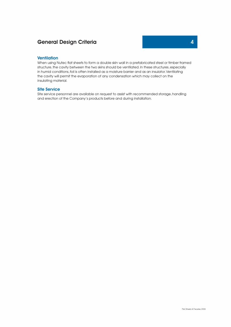
FIG. 13(A) Perspective of an External Open Corner Joint
FIG. 13(B) Plan of an External Open Corner Joint
Jointing Systems (cont.) 30
1 Outer line of main
structure
2 Timber/steel frame fixed
to
main structure
3 Silicone bead
4 50/80mm EPDM gasket
fixed
5 Nutec sheet
1 Outer line of main structure
2 Timber/steel frame fixed to
main structure
3 Silicone bead
4 50/80mm EPDM gasket fixed to
frame
5 Nutec sheet
6 Fixing pointAll dimensions in mm
Flat Sheets & Facades 2009

NUTEC SHEET FACADE (continued)
FIG. 14(A) Perspective of an Internal Open Corner Joint
FIG. 14(B) Plan of an Internal Open Corner Joint
Jointing Systems (cont.) 31
1 Outer line of main structure
2 Timber/steel frame fixed to main structure
3 50/80mm EPDM gasket fixed to frame
4 Silicone bead
5 Nutec sheet
1 Outer line of main structure
2 Timber/steel frame fixed tomain structure
3 50/80mm EPDM gasket fixed toframe
4 Silicone bead
5 Nutec sheet
All dimensions in mm
Flat Sheets & Facades 2009

NUTEC SHEETSealed Joints• For sealed joints, only silicones which are compatible with cement should be used.
• Painting over sealants is not recommended.
• The minimum joint opening should not be less than 6mm and not more than 10mm.
• The depth of the sealant should be half the sheet thickness.
• The edges of the material next to the joint should be parallel and relatively smooth.
FIG. 15 Sealed Joint Detail FIG. 16 Plan of Window Detail Showing Closed joint at Window Reveal
Jointing Systems (cont.) 32
All dimensions in mm
5 Nutec sheet
6 Timber/steel frame
7 Foam backing strip
1 Nutec sheet
2 Self tapping or rivet (optional)
3 Foam backing strip
4 Silicone sealant
5 50mm Galvanised hoop iron
1 Plaster
2 Main structure
3 Steel window
4 Silicone sealant
Flat Sheets & Facades 2009

FLAT FACADEMetal Flashing Corner Details• Metal products not supplied by EVERITE.
• External and internal finishings are optional.
FIG. 17(A) Perpective of Metal Corner FIG. 17(B) Plan of Metal Corner
FIG. 17(C) Perpective of Internal Metal Corner
Jointing Systems (cont.) 33
1 Chromaprep preformed metal
2 Maximum tolerance 3mm
3 Silicone sealant
4 Timber fixed to main structure
5 Nutec sheet
6 Outer line of main structure
1 Chromaprep preformed
metal corner piece
2 Maximum tolerance 3mm
3 Silicone sealant
4 Timber fixed to main structure
5 Nutec sheet
6 Outer line of main structure
All dimensions in mm
All dimensions in mm
Flat Sheets & Facades 2009
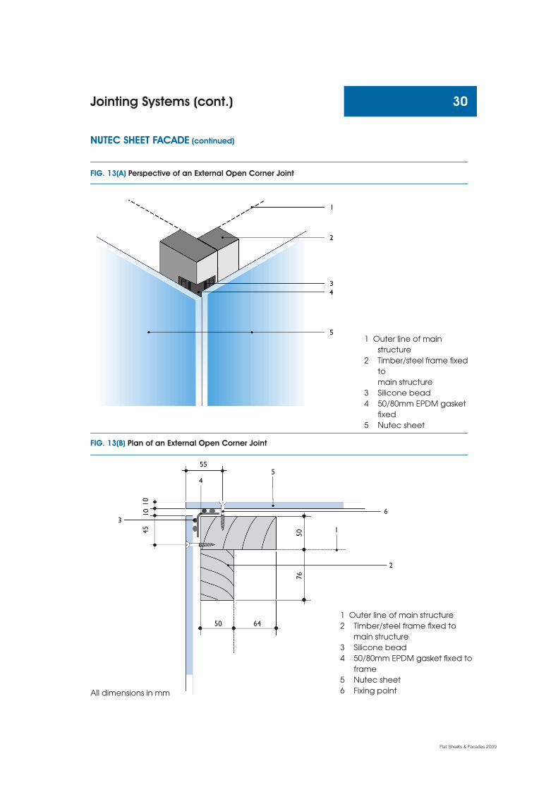
General DetailsWhere flashing is to be used on a parapet wall, it should wherever possible be sloped away
from the face of the Nutec sheet in order to avoid any discolouration of the finished surface due
to rain washing down dust onto the face of the sheet.
FIG. 18 Typical Section Through Window and Parapet Wall
FIG. 19 Section Through Windowsill
Jointing Systems (cont.) 34
1 Pressed metal capping
2 Nutec sheet
3 Box gutter
4 Structural members
5 Open or sealed joints forming
10mm drip groove
6 Nutec under eaves/soffit
7 Window
8 Window trim
1 Nutec window sill
2 Angled galvanised flashing fixed to frame
3 Silicone bead
4 Nutec sheet
5 Frame fixed to main structure
6 Outer line of main structure
Flat Sheets & Facades 2009

VentilationWhen using Nutec flat sheets to form a double skin wall in a prefabricated steel or timber framed
structure, the cavity between the two skins should be ventilated. In these structures, especially in
humid conditions, foil is often installed as a moisture barrier and as an insulator. Ventilating the cavity
will permit the evaporation of any condensation which may collect on the insulating material.
The sheets are best painted with a pure acrylic PVA paint. Where it is intended to use oil or alkyd
paints it is essential to prime the sheet with an alkali-resistant sealer. In this instance both faces of
the product should be sealed.
The Tongue and Groove Textured Board is medium density. These sheets are supplied in the natural greyand can be varnished with wood stain to simulate timber. Sheets can also be painted in varioustechniques to achieve a pleasant aesthetic finish. These boards are ideal for ceilings, internal & externalwall panelling, door panelling and garden sheds.
Tongue and Groove 35
Handling & StorageEVERITE boards are manufactured from composite materials and may be damaged under excessively
high shock loads. Reasonable care should therefore be taken to ensure that the products are not
dropped or subjected to rough handling.
A smooth level area should be made available where these products can be stacked safely.
The stacks should be supported at maximum 400mm centres and stacked clear of the ground.
They should be protected against possible damage. Stacking height should not exceed 500mm with
canterlever not exceeding 100mm.
It is recommended that products be stored covered to keep them dirt-free before installation to
prevent build-up of dust that will affect paint adhesion.
Product Range
Flat Sheets & Facades 2009
Product No. Nominal Thickness Size Average Massmm mm kg
Textured Tongue & Groove Boards
650-567 6 MD 1 200 x 2 400 24
650-568 6 MD 1 200 x 3 000 30
650-569 6 MD 1 200 x 3 600 37
060-643 9 MD 1 200 x 2 400 35
060-644 9 MD 1 200 x 3 000 44
060-645 9 MD 1 200 x 3 600 52
Plain Tongue & Groove Boards
650-566 6 MD 1 200 x 3 000 30
Tongue and Groove (cont.) 36
2
6
41
5
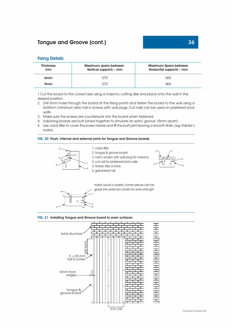
1. crack filler
2. tongue & groove board
3. nail in screen with wall plug for masonry
4. cut nail for plastered brick walls
5. timber, tiles or brick
6. galvanised nail
metal, wood or plastic corner pieces can be
glued into external corners for extra strength
1
32
6
5
Thickness Maximum spans between Maximum Spans betweenmm Vertical supports – mm Horizontal supports – mm
6mm 570 500
9mm 570 800
1.Cut the board to the correct size using a masonry cutting disk and place onto the wall in the
desired position.
2. Drill 5mm holes through the board at the fixing points and fasten the board to the wall using a
5x30mm (minimum size) nail in screws with wall plugs. Cut nails can be used on plastered brick
walls.
3. Make sure the screws are countersunk into the board when fastened.
4. Adjoining boards are butt joined together to simulate an extra ‘groove’ (5mm apart).
5. Use crack filler to cover the screw heads and fill the butt joint leaving a smooth finish, (eg. Painter’s
mate).
FIG. 20 Flush, internal and external joints for Tongue and Groove boards.
Fixing Details
FIG. 21 Installing Tongue and Groove board to even surfaces
570 CRS
tongue &groove board
10mm fromedges
5 x 25 mmnail in screw
500 M
AX
brick structure
1
5
4
3
2
Flat Sheets & Facades 2009

Tongue and Groove (cont.) 37
Things to remember when installing Tongue and Groove boards.• Tongue and Groove boards may be applied to timber frames, plastered and unplastered walls
and tiled surfaces as shown in figure 21, page 36.
• Standard dado rails can be easily attached onto the wall above or below Tongue and Groove
boards except when fixing strips are used. In such cases a shelf should be used instead.
• Fixing to uneven walls may required the use of fixing strips (figure 22) to ensure that the board
remains flat and does not follow an uneven contour.
• Fixing strips must be fastened to the wall with nail in screws at 300mm intervals. The irregularity
of the wall will determine the thickness of timber used but a minimum of 15mm should be adhered
to.
• Spacer must be used at relevant fixing points behind the strips to compensate for the irregularities
in the wall. A builders line must be used to draw a level across the strips.
• Tongue and Groove boards are attached to the fixing strips at the same intervals as they would
normally be attached using.
• For ceiling applications these boards should be fixed at 600m centers as shown in figure 23,page 38.
• When used in wet areas, the board must be sealed continuously around the perimeter of the
reverse side of the board 5mm from the edge.
Fixing DetailsFIG. 22 Installation of Tongue and Groove board to uneven surfaces
existingwall tiles
rawl plugø5 x 25
fixing strips@ 300 crs
300
tongue& grooveboards
brickstructure
Flat Sheets & Facades 2009

Fixing Details
NB: • Timber or steel framing may be used and should be constructed in accordance with local buildingregulations and acceptable building practice.
• Timber should be selected structural grade timber.• Timber supports must be firmly secured to top and bottom plates and frames must not rely on
the Nutec sheets for stability.• Support spacings for external or internal walls should not exceed 600mm centres.• Framing members, should be arranged to support all sheet edges.• Where the support faces behind sheet joints are less than 38mm wide, pack out to provide
additional landing for sheet fixing.• For further information on timber framed structures refer to SABS 082-1975.
FIG. 23 Installing the Tongue & Groove as a Ceiling
1. tie beam2. brandering3. wallplate4. nutec ceiling board5. h-profile jointing strip6. wall
1
2
3
4
5
6
Tongue and Groove (cont.) 38
Flat Sheets & Facades 2009

Description Quantity Rate AmountEVERITE high density Nutec sheets (uncoated),
medium density plain Nutec sheets (uncoated),
moulded panels (uncoated), fitting & fixing
accessories fixed to (specify type and material of
battens or sheeting rails). Battens, sheeting rails
and supporting substructure elsewhere
measured,including all cutting and waste
(measured net).
1. Flat Sheetsa) EVERITE high density Nutec sheet
(quote relevant dimensions of sheet)
(measured net) m2
or
b) EVERITE Nutec medium density
Nutec sheet (quote relevant
dimension of sheet) m2
2. Accessoriesa) Metal flashing with silicone for horizontal
open joints (specify size and type of metal
flashing) m
or
b) EPDM gasket for vertical joints
(specify size and relevant product number) m
or
c) EPDM gasket for vertical corner joints
(specify size and relevant product number) m
or
d) Galvanised hoop iron cover strip used
behind panel (specify type and size of joint)
by others m
or
e) Silicones for joint fillers (specify type and
size of joint) by others m
or
f) Foam backing strip for jointing
(specify type and size) by others m
or
g) Extra over for filling in
Sample Bill of Quantities 39
Flat Sheets & Facades 2009

40
Call Centre - 0861 333 835www.everite.co.za
Flat Sheets & Facades 2009
Everite National Offices
Sales Support OfficeP O Box 8644 Johannesburg 2000
Heidelberg Road Kliprivier Gauteng
Telephone (011) 439 4400
Telefax (011) 903 7097
Cape TownP O Box 26 Brackenfell 7561
Ground Floor Corporate Place
Mispel Street Belville
Telephone (021) 941 8640
Telefax (021) 941 8641
DurbanP O Box 1532 Wandsbeck 3631
1st Floor Kent House
1 Neptune Road Essex Terrace
Westville 3629
Telephone (031) 267 1903
Telefax (031) 267 1907
BloemfonteinP O Box 981 Bloemfontein 9300
76/80 President Reitz Street
Reitz Park Westdene
Telephone (051) 448 7433
Telefax (051) 448 7435
East LondonP O Box 679 East London 5200
3 Suffolk Road Berea
Mobile (079) 516 6510
Telefax (043) 726 0343
GeorgeP O Box 444 George 6530
Building Exhibit Centre
Corner Market & Hope St George
Telephone (044) 873 2408
Mobile (083) 286 3435
Telefax (044) 873 2409
Middelburg (Mpumalanga)P O Box 7017 Kanonkop
Middelburg 1050
Mobile (083) 778 2787
Telefax (013) 244 2629
PolokwaneP O Box 552
Polokwane 0700
26, 20th Avenue Industria
Telephone (015) 297 3559/62
Telefax (015) 297 3424
Port ElizabethP O Box 34323
Newton Park 6055
Propnet Park Ries Street
Deal Party
Telephone (041) 401 8900
Mobile (083) 780 6162
Telefax (041) 486 1884
WorcesterP O Box 492
Worcester 6851
1 Nassau Street Worcester
Mobile (083) 286 3431
Telefax (023) 342 6966
Botswana (Gaborone)Private Bag 003 Suite 466
Mogoditshane
Botswana
Mobile (00267) 7 263 9887
Telefax (00267) 316 7753
NamibiaP O Box 894
Swakopmund
Mobile (00264) 81 124 2655
Telefax (00264) 64 40 3733