Embed Size (px)
Citation preview
The upgrade offers a specially modified rotary segment ball valve, actuator, pressure instrumentation and digital controller packaged in a single assembly.
The assembly consists of the following components:
(1) Segment ball valve: gives increased turndown and greatly increased profile repeatability. The stainless steel valve is rated at ASME class 300 and is approved to NACE standards.
(2) Flexible coupling (keyed): a single element anti-backlash flexible coupling to allow for angular misalignment between the coupling and actuator.
Siemens Industrial Turbomachinery Ltd has recently introduced an upgrade to the gas fuel system incorporating an Integrated Fuel Valve (IFV) assembly and, where applicable, pneumatically actuated fast acting double block and vent valves.
Answers for Energy
www.siemens.com/energy
Integrated Fuel Valve (IFV)Gas Fuel System UpgradeFor Industrial Gas Turbines up to 15 MW
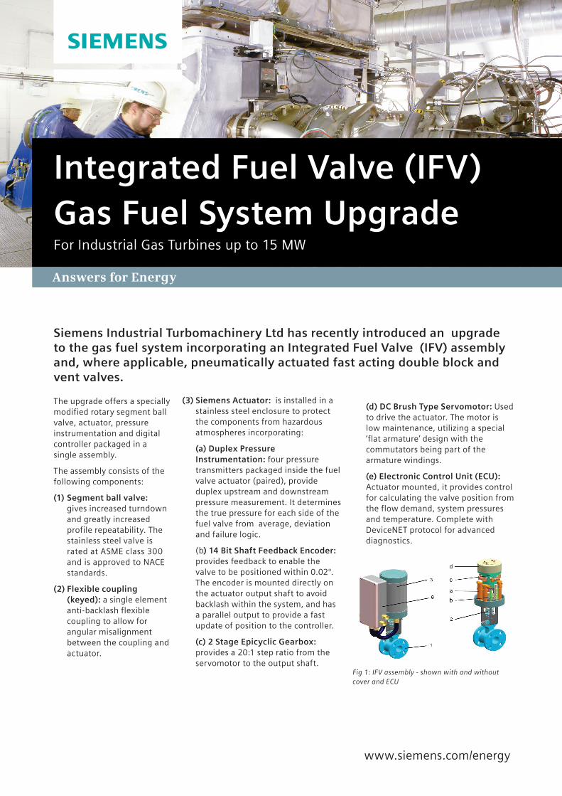
(3) Siemens Actuator: is installed in a stainless steel enclosure to protect the components from hazardous atmospheres incorporating:
(a) Duplex Pressure Instrumentation: four pressure transmitters packaged inside the fuel valve actuator (paired), provide duplex upstream and downstream pressure measurement. It determines the true pressure for each side of the fuel valve from average, deviation and failure logic.
(b) 14 Bit Shaft Feedback Encoder: provides feedback to enable the valve to be positioned within 0.02°. The encoder is mounted directly on the actuator output shaft to avoid backlash within the system, and has a parallel output to provide a fast update of position to the controller.
(c) 2 Stage Epicyclic Gearbox: provides a 20:1 step ratio from the servomotor to the output shaft.
Fig 1: IFV assembly - shown with and without cover and ECU
(d) DC Brush Type Servomotor: Used to drive the actuator. The motor is low maintenance, utilizing a special ‘flat armature’ design with the commutators being part of the armature windings.
(e) Electronic Control Unit (ECU): Actuator mounted, it provides control for calculating the valve position from the flow demand, system pressures and temperature. Complete with DeviceNET protocol for advanced diagnostics.
www.siemens.com/energy
Published by and copyright © 2013:Siemens AGEnergy SectorFreyeslebenstrasse 191058 Erlangen, Germany
Siemens Energy, Inc.4400 Alafaya TrailOrlando, FL 32826-2399, USA
For more information, please contact our Customer Support Center.Phone: +49 180 524 70 00 Fax: +49 180 524 24 71 (Charges depending on provider)E-mail: [email protected]
Energy Service DivisionLCN 2013 - F33.22 LN
Printed on elementary chlorine-free bleached paper.
All rights reserved. Trademarks mentioned in this document are the property of Siemens AG, its affiliates, or their respective owners.
Subject to change without prior notice. The information in this document contains general descriptions of the technical options available, which may not apply in all cases. The required technical options should therefore be specified in the contract.
Fast Acting Double Block & Vent Valves
In conjunction with the Integrated Fuel Valve, the system includes a further package of safety equipment: -
An on-skid fast-acting double block and vent valve assembly to enable removal of the existing pressure proving system (if fitted).
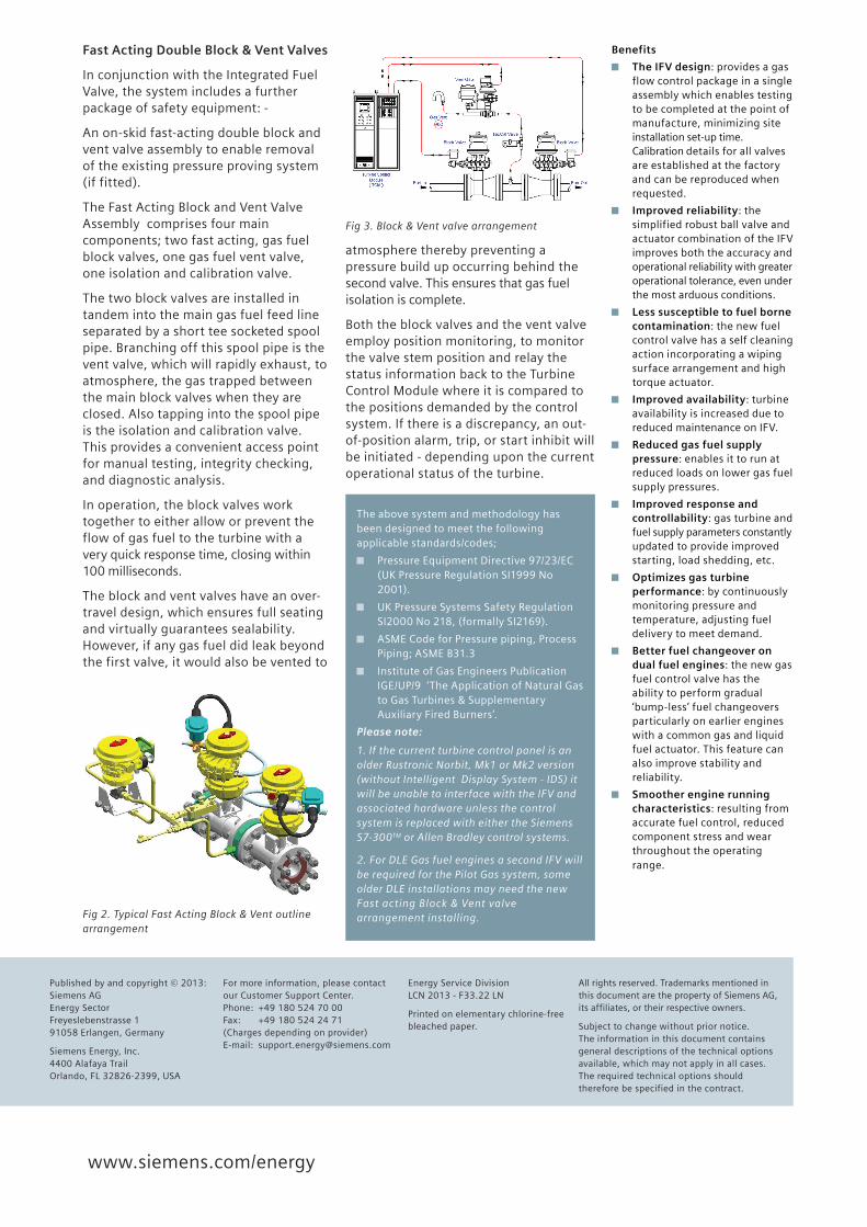
The Fast Acting Block and Vent Valve Assembly comprises four main components; two fast acting, gas fuel block valves, one gas fuel vent valve, one isolation and calibration valve.
The two block valves are installed in tandem into the main gas fuel feed line separated by a short tee socketed spool pipe. Branching off this spool pipe is the vent valve, which will rapidly exhaust, to atmosphere, the gas trapped between the main block valves when they are closed. Also tapping into the spool pipe is the isolation and calibration valve. This provides a convenient access point for manual testing, integrity checking, and diagnostic analysis.
In operation, the block valves work together to either allow or prevent the flow of gas fuel to the turbine with a very quick response time, closing within 100 milliseconds.
The block and vent valves have an over-travel design, which ensures full seating and virtually guarantees sealability. However, if any gas fuel did leak beyond the first valve, it would also be vented to
Fig 2. Typical Fast Acting Block & Vent outline arrangement
atmosphere thereby preventing a pressure build up occurring behind the second valve. This ensures that gas fuel isolation is complete.
Both the block valves and the vent valve employ position monitoring, to monitor the valve stem position and relay the status information back to the Turbine Control Module where it is compared to the positions demanded by the control system. If there is a discrepancy, an out-of-position alarm, trip, or start inhibit will be initiated - depending upon the current operational status of the turbine.
Fig 3. Block & Vent valve arrangement
Benefits
The IFV design: provides a gas flow control package in a single assembly which enables testing to be completed at the point of manufacture, minimizing site installation set-up time. Calibration details for all valves are established at the factory and can be reproduced when requested.
Improved reliability: the simplified robust ball valve and actuator combination of the IFV improves both the accuracy and operational reliability with greater operational tolerance, even under the most arduous conditions.
Less susceptible to fuel borne contamination: the new fuel control valve has a self cleaning action incorporating a wiping surface arrangement and high torque actuator.
Improved availability: turbine availability is increased due to reduced maintenance on IFV.
Reduced gas fuel supply pressure: enables it to run at reduced loads on lower gas fuel supply pressures.
Improved response and controllability: gas turbine and fuel supply parameters constantly updated to provide improved starting, load shedding, etc.
Optimizes gas turbine performance: by continuously monitoring pressure and temperature, adjusting fuel delivery to meet demand.
Better fuel changeover on dual fuel engines: the new gas fuel control valve has the ability to perform gradual ‘bump-less’ fuel changeovers particularly on earlier engines with a common gas and liquid fuel actuator. This feature can also improve stability and reliability.
Smoother engine running characteristics: resulting from accurate fuel control, reduced component stress and wear throughout the operating range.
Please note:
1. If the current turbine control panel is an older Rustronic Norbit, Mk1 or Mk2 version (without Intelligent Display System - IDS) it will be unable to interface with the IFV and associated hardware unless the control system is replaced with either the Siemens S7-300TM or Allen Bradley control systems.
2. For DLE Gas fuel engines a second IFV will be required for the Pilot Gas system, some older DLE installations may need the new Fast acting Block & Vent valve arrangement installing.
The above system and methodology has been designed to meet the following applicable standards/codes;
Pressure Equipment Directive 97/23/EC (UK Pressure Regulation SI1999 No 2001).
UK Pressure Systems Safety Regulation SI2000 No 218, (formally SI2169).
ASME Code for Pressure piping, Process Piping; ASME B31.3
Institute of Gas Engineers Publication IGE/UP/9 ‘The Application of Natural Gas to Gas Turbines & Supplementary Auxiliary Fired Burners’.