Embed Size (px)
Citation preview

ORNL-TM-3725
MASTER* VALVE FAILURE IN THE ORNL FUEL FAILURE
MOCKUP LIQUID METAL FACILITY
J. W . Koger
>"•' • t.-.'i i' j i ' • -11 "•'i.V.V'
OAK RIDGE NATIONAL LABORATORY OPERATED BY UNION' CARBIDE CORPORATION • "-FOR. THE (J S. ATOMIC ENERGY COMMISSION

ORNL-TM-3725
Contract No. W-7405-eiig-26
METALS AND CERAMICS DIVISION
VALVE FAILURE IN THE ORNL FUEL FAILURE MOCKBP "QUID ™ ^ ^
j. w. Koger -NOTICE-This report was prepared as an account of work sponsored by the United States Government. Neither the United States nor the United States Atomic Energy Commission, nor any of their employees, nor any of their contractors, subcontractors, or their employees, makes any warranty, express or implied, or assumes any legal liability or responsibility for the accuracy, com-pleteness or usefulness of any information, apparatus, product or process disclosed, o; represents that its use would not infringe privately owned rights.
AUGUST 1972
hot.CE This
not represent a f inal report.
OAK RIDGE NATIONAL LABORATORY Oak Ridge, Tennessee 37830
operated by UNION CARBIDE CORPORATION
for the U.S. ATOMIC ENERGY COMMISSION
piSTRJBUTKTO OF THIS DOCUMENT 1SUNUM1TED

iii
CONTENTS
Page
Abstract 1 Introduction . . . . . 1 Results 3
Two and One-Half Inch Valve 3 One-Half Inch Valve 15
Discussion 15 Two and One-Half Inch Valve 15 One-Half Inch Valve 22
Conclusions 23 Acknowledgments . 23

VALVE FAILURE IN THE ORNL FUEL FAILURE MOCKUP LIQUID METAL FACILITY
J. W. Roger
ABSTRACT
Examination of two valves, a 2 1/2-in. throccling valve and a 1/2-in. drain valve, that failed and caused a sodium leak in the Fuel Failure Mockup system disclosed that both failures occurred in the bellows core. Detailed metallurgi-cal examinations of both bellows cores were conducted. Several convolutions of the 2 1/2-in. valve bellows core were deformed, and two sodium leak sources were found in highly stressed areas near edge welds. The examination indicates the initial sodium leak was through a crack caused by the deformation. Sodium then reacted with air causing gross corrosion on the air side of the bellows until the leak increased to a detect-able level. The failure in the 1/2-in. valve was attributable to either improper formation of the first convolution or mis-handling of the lower part of the bellows assembly during welding to the valve.
INTRODUCTION
The Fuel Failure Mockup (FFM) is a large high-temperature sodium facility in which simulated LMFBR core segments (19-pin bundles of internally heated electrical heaters) are subjected to thermal and hydraulic testing at typical operation conditions. The system was filled with sodium on December 6, 1971, in preparation for a run with Bundle 2A heater pins which had just been installed. The accumulated operating time to that date was 1300 hr and the system sodium tempera-ture had been varied between 600 and 1100°F. On December 8, a leak was detected in a valve (2 1/2-in. Sched 40) located at the test section inlet. The loop was operating at 600°F and 21 gpm sodium flow with 5 psig argon pressure on the pump bowl at the time of the failure. Approximately 1 pt to 1 qt of sodium was lost from the system inventory before the automatic drain controls caused the sodium to drain into the sump tank. There was no evidence of fire and no other significant damage.
2
The failed valve was a 2 1/2-in. bellows-sealed throttling valve manufactured by the Mason-Neilan Company. This type valve was origi-nally designed to operate at 1540°F and 25 psig in the Intermediate Potassium System (IPS), a boiling potassium Rankine cycle facility.1
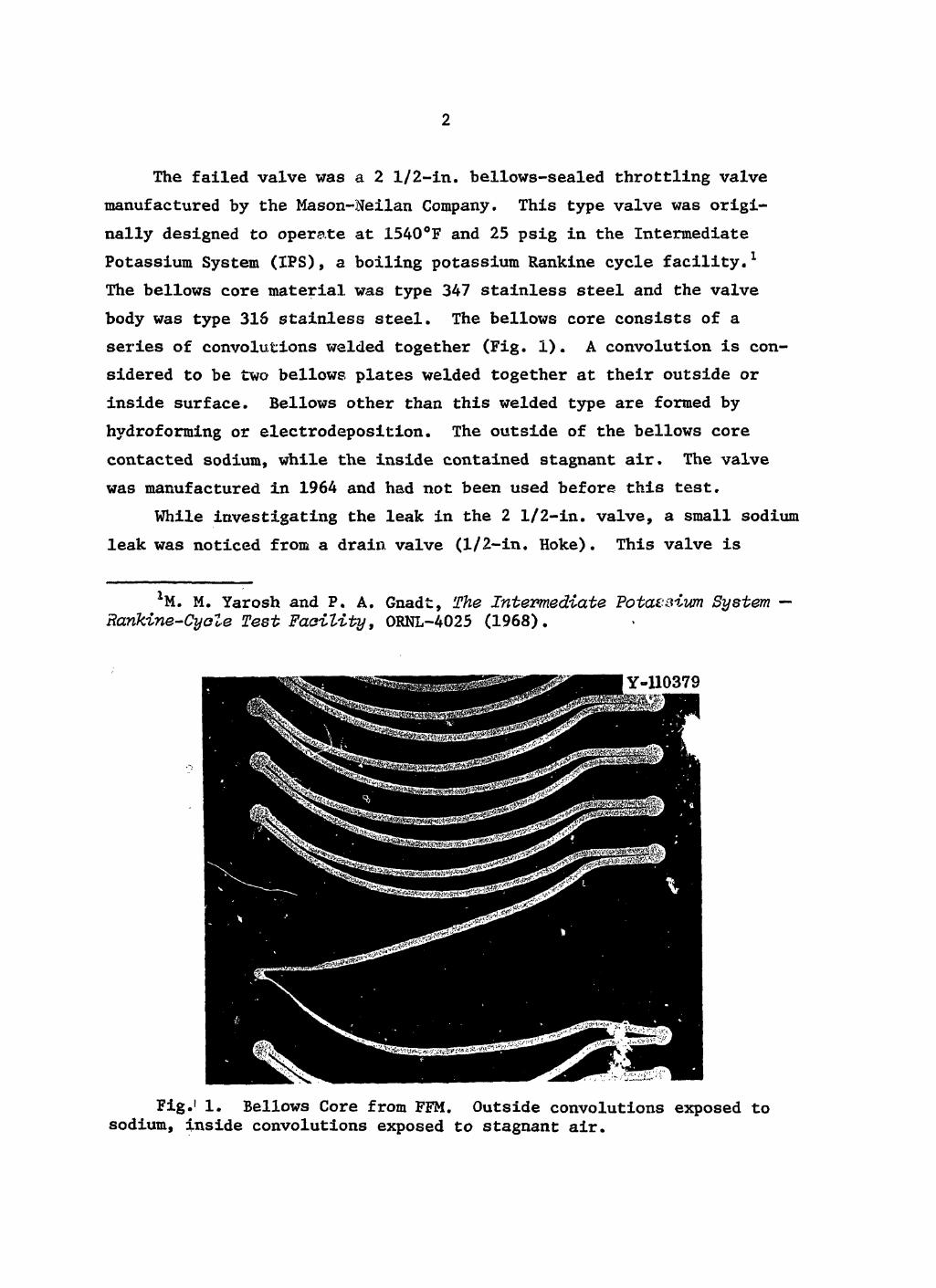
The bellows core material was type 347 stainless steel and the valve body was type 315 stainless steel. The bellows core consists of a series of convolutions welded together (Fig. 1). A convolution is con-sidered to be two bellows plates welded together at their outside or inside surface. Bellows other than this welded type are formed by hydroforming or electrodeposition. The outside of the bellows core contacted sodium, while the inside contained stagnant air. The valve was manufactured in 1964 and had not been used before this test.
While investigating the leak in the 2 1/2-in. valve, a small sodium leak was noticed from a drain valve (1/2-in. Hoke). This valve is
M. M. Yarosh and P. A. Gnadt, The Intermediate PotdCS turn System — Rankine-CyoZe T e s t F a e i . l i . t y , ORNL-4025 (1968).
Fig.1 1. Bellows Core from FFM. Outside convolutions exposed to sodium, inside convolutions exposed to stagnant air.

3
remotely operated to drain the system by a pneumatic actuator that is opened automatically by an abnormal condition during unattended opera-tion. This valve had been actuated through about 50 open-close cycles at room temperature prior to installation to check the reliability of the operation and was automatically operated several times during the life of this facility. The bellows material in this valve was type 347 stainless steel, and the valve body was type 316 stainless steel, The 1/2-in. valve was designed for 50 psig at 1500°F and was manufactured in 1969. This valve was also unused when installed into the FFM.
Both valves were removed from the facility for examination, and this report emphasizes the metallurgical examination made in an effort to determine the causes of the failure.
RESULTS
Two and One-Half Inch Valve
The valve, after removal from the FFM system, was soaked in butyl alcohol until gas evolution ceased which signified the removal of all sodium. Water and ethyl alcohol were then used for subsequent rinses, A circumferential cut was made to separate the upper valve assembly (i.e., stem, plug, and bellows) from the valve body as shown in Fig. 2. Figure 2 (right to left) shows a valve before disassembly, a valve stem, plug, and bellows assembly separated from the valve body, and a valve stem, plug, and bellows assembly separated from the valve body of the failed valve. The upper valve assembly was then soaked in butyl alcohol and rinsed with ethyl alcohol and distilled water. The bellows assembly was then cut from the valve subassembly for detailed metallurgical exam-ination. The cut was made through adapters which were welded to the valve plug on one end and the valve body on the other.
Cursory examination of the bellows core from the failed valve dis-closed widely separated convolutions at three different locations in the assembly (Fig. 3). A leak test of the bellows core disclosed a hole jiear the root of one of the separated convolutions. The sodium-side bellows

Fig. 2. Two and One-Half Inch Valves Used in FFM. From left to right, dismantled failed valve dismantled replacement valve, complete replacement valve. V V e >

5
Fig. 3. Stem, Bellows Assembly, and Plug from 2 1/2-in. Valve. Fuel Failure Mockup sodium leak was from bellows on left side. Right side components are replacements.

6
core surface was clean, as would be expected of stainless steel which has been exposed to sodium.
Figure 4 shows the hole detected by the leak check, the excessive separation of the convolutions, and a badly damaged area just above the failure. A vertical cut of the bellows core was made through the hole and is seen in Fig. 5. The convolutions on .the left (horizontal welded ends) are located on the sodium side (outside), while the convolutions
Y-110112
Fig. 4. Welded Bellows Core from the 2 1/2-in. FFM Valve Showing Hole that Caused Sodium Leak and the Deformed Convolutions,

Fig. 5. Cross Section Sliced Through the Source of the Sodium Leak of the Bellows Core from the 2 1/2-in, FFM Valve.
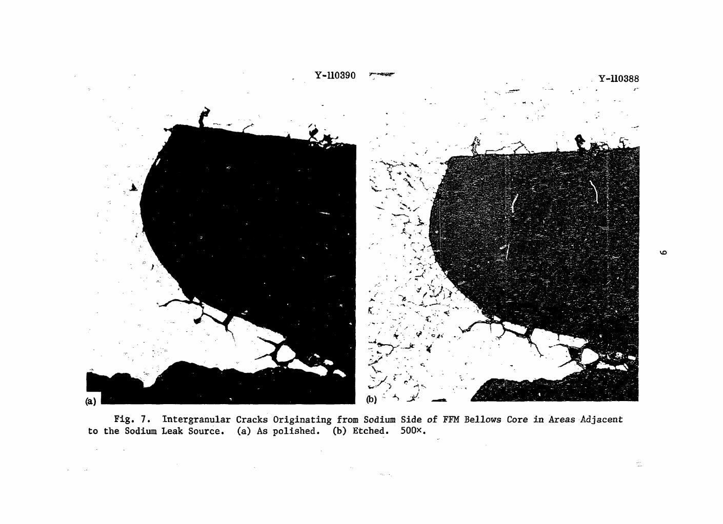
on the right (curved welded ends) are located on the stagnant air side. Figure 6 is a higher magnification of the failure, an* iiuce we note that more material was removed from the air side than the sodium side at the failure, we conclude that the direction of the gross attack was from the air side. Figure 7 is a micrograph of the area adjacent to the failure. Note the intergranular attack on the sodium side.
Figure 8 shows an attacked area located on the air side of tl. i. bellows core several convolutions away from the hole. A cut through this area gives the result shown in Fig. 9. Severe attack is noted on the air side of the convolutions. Closer examination reveals that one set of convolutions is distorted. This distortion, unlike the separated convolutions of Fig. 3, could not be seen unmagnified. Figure 10 shows a higher magnification of the deformed convolution. The extent of the air side attack should also be noted along with the severe intergranular penetration. Figure 11 shows a magnification of the intergranular attack and discloses a crack completely through the

8 i i
Fig. 6. Source of the Sodium Leak in the Bellows Core of the 2 1/2-in. FFM V&lve. 100x.
Y-110390 r***®" Y-110388
vo
Fig. 7. Intergranular Cracks Originating from Sodium Side of FFM Bellows Core in Areas Adjacent to the Sodium Leak Source, (a) As polished, (b) Etched. 500x.

xo
• • ( • l ^ ^ ^ ^ r B e U o v s Core
^ * Core £*om _ B e l l o v s 9 * .
^ c r o s s S e c t ^ of m -
Valve Sliced T K

1 1
Fig. 10. Heavily Attacked and Slightly Deformed FFM Bellows Core Convolution, (a) As polished, (b) Etched. 100x.

12
Y-11039
Fig. 11. Localized Intergranular Cracks Primarily Originating from Sodium Side of FFM Bellows Core. Note the path completely through the metal. 500*.
material. Also seen are several other intergranular cracks completely surrounding some grains. From these observations it is obvious that there was at least one other sodium leak in the bellows, and that this leak was not detected by the original leak test. It follows that the material found on the bellows core, shown in Fig. 8, was corrosion pro-ducts resulting from the sodium leak at that location.
Figure 12 shows another set of deformed convolutions from the failed valve. No cracks were detected here. Again we see corrosive attack from the air side. Figure 13 shows mild attack of the air side of a relatively undeformed convolution just above the convolution sepa ration of Fig. 12.
Figure 14 shows three sodium-side convolutions under various condi-tions of corrosive attack resulting from the original failure. In

13
Fig. 12. Cross Section of the FFM Bellows Core Sliced Through a Deformed Convolution. 9x.
Fig. 13. Undeformed Convolution of the FFM Bellows Core Attacked on the Air Side. 100x.

14
Fig. 14. Sodium-Side Convolutions of the FFM Bellows, (a) As fabricated, (b) Disks separated by deformation of the bellows core, (c) Disks separated by deformation of the bellows core with corrosion products migrating toward the end weld. Etched. 100x.

15
Fig. 14(a) the convolution is shown as fabricated with no separation or attack. In Fig. 14(b) the convolutions have been separated by deforma-tion of the bellows as in Fig. 5. In Fig, 14(c) the convolutions have again been separated, and corrosion products have migrated between the disks to the weld area as seen in Fig. 9.
Radiography of the other 2 1/2-in. valve in the FFM system disclosed that convolution separations were present, and it was subsequently removed from service. After thit> second valve was disassembled two convolution separations were noted (Fig. 15). No detailed examination of this valve was conducted.
One-Half Inch Valve
Figure 16 shows a complete valve and the failed valve with the bellows assembly exposed. On removal from the system, this valve was also soaked in butyl alcohol to remove traces of sodium. Water and ethyl alcohol were used as final rinses. This bellows core was formed as opposed to welded. Sodium contacted the inside of the bellows core with air on the outside. Figure 17 shows a magnification of the inside of the bellows core and one-half of the horizontal crack that ran along the top of the convolution. The crack extended 180° along the circum-ference. The longitudinal tear was a result of removing the bellows assembly from the valve and cutting the bellows core for examination.
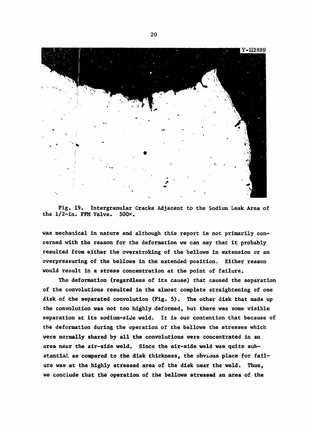
Figure 18 shows a cross section of the failed area. The etched photomicrograph shows deformed grains similar to those seen near a ten-sile failure. Figure 19 shows an area adjacent to the failure with several cracks originating from the sodium side.
DISCUSSION
Two and One-Half Inch Valve
The examination indicates that the sodium leaks in the 2 1/2-in. valve were directly attributable to the deformation that caused the separation of the convolutions. The separation of the convolutions

16
Fig. 15. Deformed Bellows Assembly and Plug from 2 1/2-in. Valve Exposed to Sodium 1300 hr at 600 to 1100°F in FFM Facility.

Fig. 16. Left - Replacement 1/2-in. Val^s. Right - Failed 1/2-in. FFM Valve with Formed Bellows Core Exposed.

18
[Y-110114
i
... V™*
lv
ir
-• „ X'M
Note t h l ' c i ^ J ^ i a T ^ r ^ T t o T o V ™ ™ coP o t t h e bottom convolution.

Fig. 18. Cross Section of the Bellows Core from the 1/2-in. FFM Valve. 100*. (c) Etched, 100*. Reduced 33.5%.
(a) 33x. (b) As polished,
20
Fig. 19. Intergranular Cracks Adjacent to the Sodium Leak Area of the 1/2-in. FFM Valve. 500x.
was mechanical in nature and although this report is not primarily con-cerned with the reason for the deformation we can say that it probably resulted from either the overstroking of the bellows in extension or an overpressuring of the bellows in the extended position„ Either reason would result in a stress concentration at the point of failure.
The deformation (regardless of its cause) that caused the separation of the convolutions resulted in the almost complete straightening of one disk of ithe separated convolution (Fig. 5). The other disk that made up the convolution was not too highly deformed, but there was some visible separation at its sodium-side weld. It is our contention that because of the deformation during the operation of the bellows the stresses which were normally shared by all the convolutions were concentrated in an area ne*tr the air-side weld. Since the air-side weld was quite sub-stantial as compared to the disk thickness, the obvious place for fail-ure was at the highly stressed area of the disk near the weld. Thus, we conclude that the operation of the bellows stressed an area of the

21
disk adjacent to the air-side weld eventually leading to a crack. Imme-diately after formation of the crack some sodium leaked to the air side of the bellows core (Figs. 5, 6, 9, 10, and 11). The corrosive compound which resulted from the mixture of sodium and stagnant air with its attendant moisture then attacked the stainless steel from the air side for some period of time. This long-time corrosion was evidenced by the large amount of material removed from the air side of the bellows core, as seen in Figs. 5, 6, 8, 9, 10, 12, and 13. Other investigators2^4
have also shown that, after the development of an initial sodium leak, the buildup of leaking sodium and reaction products produces gross external attack on the surrounding metal.
Some intergranular corrosion (Figs. 7 and 11) was seen on the sodium side of the convolutions that had cracked. Generally, stainless steel is not penetrated by sodium significantly during exposures at tempera-tures up to and including 650°C.If Intergranular penetration by sodium has been found in stainless steel (1) that had interconnected stringers that were dissolved by the sodium,5'6 (2) when the sodium has an appre-ciable oxygen content,7 and (3) when traces of trapped sodium oxide8
or sodium hydroxide9 remain on the metal, and the specimen is reheated
2R. K. Wagner and J. D. Stearns, "Evaluation of Non Fuel Materials Behavior in HNPE," Proceedings of the Sodium Components Development Program Information Meeting, June 16—17, 1965, CONF-650620.
3W. T. Lee, "Sodium Hot Trap Failure Analysis," LMEC-Memo-69-27, September 25, 1969.
'"'Sodium Piping and Component Failures at the Large Components Test Loop (LCTL)," LMEC-Memo-71-5, July 15, 1971, pp. 46-53.
5W. E. Ruther, E. L. Kimont, T. D. Claar, and J.Y.N. Wang, ANL-7849 (October 1971).
6W. E. Ruther, T. D. Claar, S. Greenberg, and R. V. Strain, ANL-7771 (April 1971).
7E. G. Brush, Corrosion II, p. 299t (1955). 8P. P a t r i a r c a , Fuels and Materials Development Program Quart. Progr.
Rept. March 31s 1971, ORNL-TM-3416, pp. 161-165. 9W. E. Ruther, T. D. Claar, and R. V. Strain, "Evaluation of Mate-
rials Compatibility Problems in the EBR-II Reactor," pp. 92-94 in Proceedings of the Sessions on Corrosion by Liquid Metals of the 1969 Fall Meeting of the Metallurgical Society of AIME, October 13—16, 1969, Philadelphia, Pennsylvania.

22
to high temperature in sodium resulting in caustic-stress corrosion.** In our case the intergranular penetration was probably due to locally contaminated sodium at the location of the cracks and occurred after the leak between the sodium and the air had become large enough to mix the two compounds. Finally, in one of the craclced areas, after some time a large enough hole was formed at the site of the deformation crack to allow sodium to escape in a quantity to be detected (Figs. 5 and 6). In the other cracked area (Figs. 10 and 11) the leak was still quite small. Fortunately cracks had not formed at all the highly stressed areas (separated convolutions) as evidenced by the unattacked deformed convolution of Fig. 12 and by the lack of corrosion on the sodium side of the bellows core.
Recent bellows core failures in sodium systems have resulted from (1) leaks of bellows material that contained stringers of nonmetallic inclusions that were dissolved by sodium,6 and (2) intergranular cor-rosion resulting from sodium hydroxide left in microlaps on the bellows when the bellows were previously used in a contaminated system9 and transgranular and intergranular attack resulting from a contaminant, probably chloride salts, which were left during fabrication. ** In order to* be complete in our analysis, we considered all the above possibilities with respect to our system. There was no evidence of contaminants and no stringers. All the evidence obtained from our analysis of the FFM failure indicated that gross permanent deformation of the 2 1/2-in. valve resulted in the overstressing of certain convolutions and led to the eventual failure.
One-Half Inch Valve
The 1/2-in. valve failure can be attributed to problems encountered during the forming of the bellows or during the joining of the bellows to the end plug. The tearing of the convolution could have occurred during operation of the valve if that convolution were highly overstressed. The microstructure of the failure showed large amounts of deformation as if overstressing had occurred. It should again be mentioned that

23
this valve had been operated many times, and we postulate a small crack that developed over a period of time to a large opening.
CONCLUSIONS
It was concluded that: 1. The sodium leak that occurred in the 2 1/2-in. valve was
caused by a mechanical deformation of the bellows. 2. The initial sodium leak in the 2 1/2-in. valve occurred at a
highly stressed region near an air-side convolution weld. 3. Subsequent to the time that the initial leak became detectable,
extensive corrosion occurred on the air side of the 2 1/2-in. valve bellows.
4. The sodium leak that occurred in the 1/2-in. valve was due to strain-induced cracking of a bellows convolution caused by improper for-mation of the first convolution or by mishandling of the lower part of the bellows during welding to the valve.
ACKNOWLEDGMENTS
It is my pleasure to acknowledge the assistance of various members of the Reactor Division, in particular P. A. Gnadt, G. E. Mills, R. E. MacPherson, and Bettye Seivers. Special thanks are extended to the following members of the Metals and Ceramics Division: C. E. Zachery of the Metallography Group, J. H. DeVan and T. S. Lundy of the Corrosion Group, and Sharon Woods of the Reports Office.