Embed Size (px)
Citation preview
THE POWER�OF FLIGHT
104/02/2006RXCF
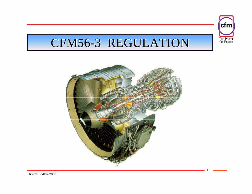
CFM56CFM56--3 REGULATION3 REGULATION
THE POWER�OF FLIGHT
204/02/2006RXCF
CFM56CFM56 -- 33

THE POWER�OF FLIGHT
304/02/2006RXCF
ENGINE OPERATIONAL CONTROLENGINE OPERATIONAL CONTROL
MECMEC PMCPMC
Main Tasks Additional Tasks
Speed Governing System
Idling System
Fuel Limiting System
VBV
VSV
HPTCCV N1 Vs Z
N1 Vs P
N1 Vs T
Corrections
CFMCFM 56 56 -- 33

THE POWER�OF FLIGHT
404/02/2006RXCF
ENGINE OPERATIONAL ENGINE OPERATIONAL CONTROLCONTROL
• The CFM56CFM56--33 engine control system consists of both:
HYDRO MECHANICAL UNIT
ELECTRONIC UNIT
THE POWER�OF FLIGHT
504/02/2006RXCF
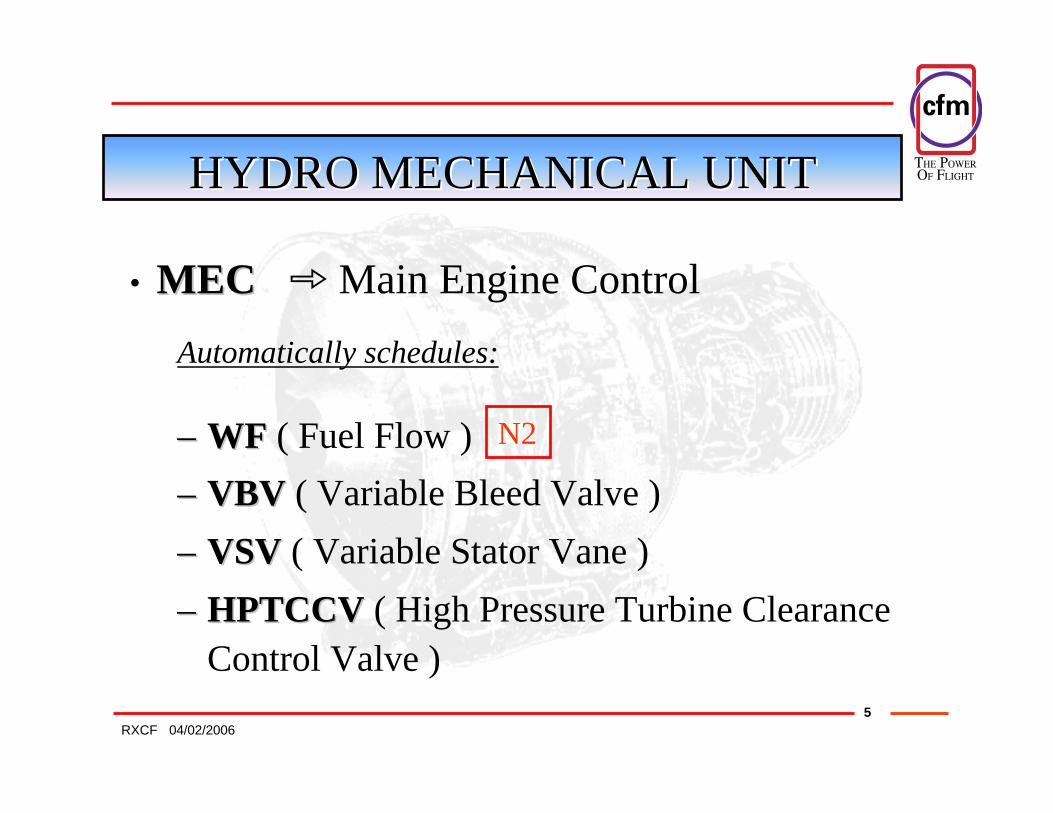
HYDRO MECHANICAL UNITHYDRO MECHANICAL UNIT
–– WFWF ( Fuel Flow )–– VBVVBV ( Variable Bleed Valve )–– VSVVSV ( Variable Stator Vane )–– HPTCCVHPTCCV ( High Pressure Turbine Clearance
Control Valve )
• MECMECAutomatically schedules:
N2
Main Engine Control
THE POWER�OF FLIGHT
604/02/2006RXCF
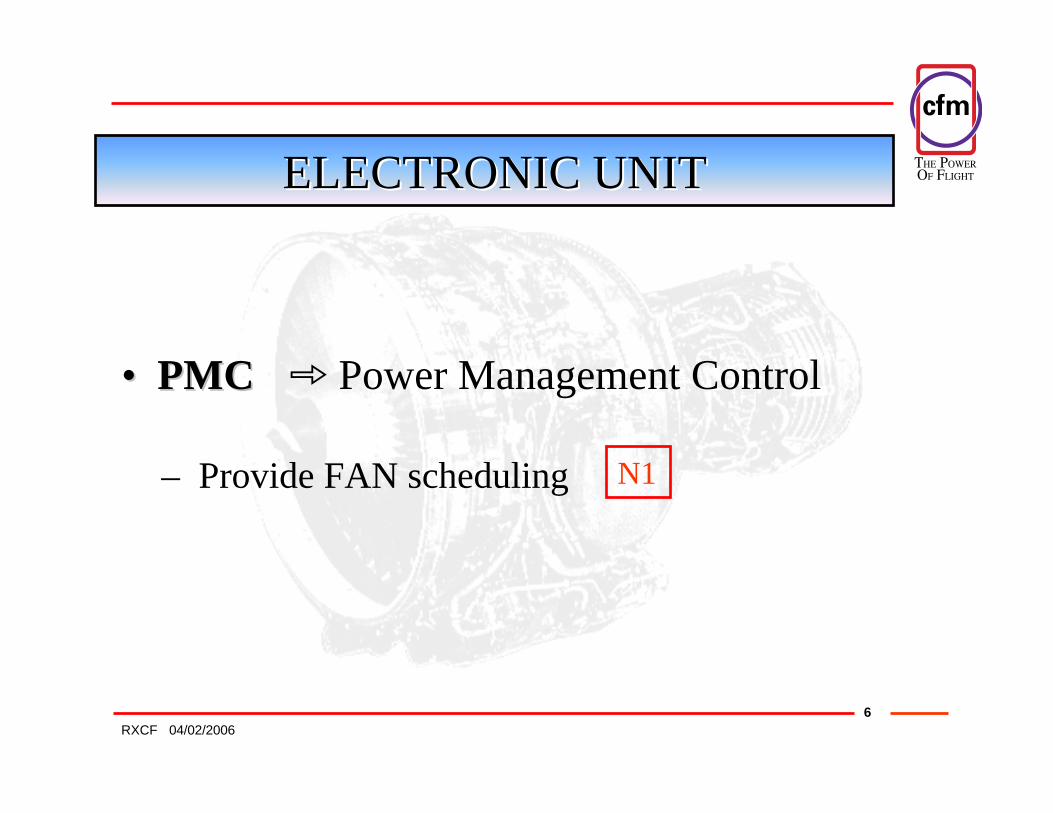
ELECTRONIC UNITELECTRONIC UNIT
•• PMCPMC Power Management Control
– Provide FAN scheduling N1

THE POWER�OF FLIGHT
704/02/2006RXCF
CONTROL SYSTEM SCHEMATIC CONTROL SYSTEM SCHEMATIC
THE POWER�OF FLIGHT
804/02/2006RXCF
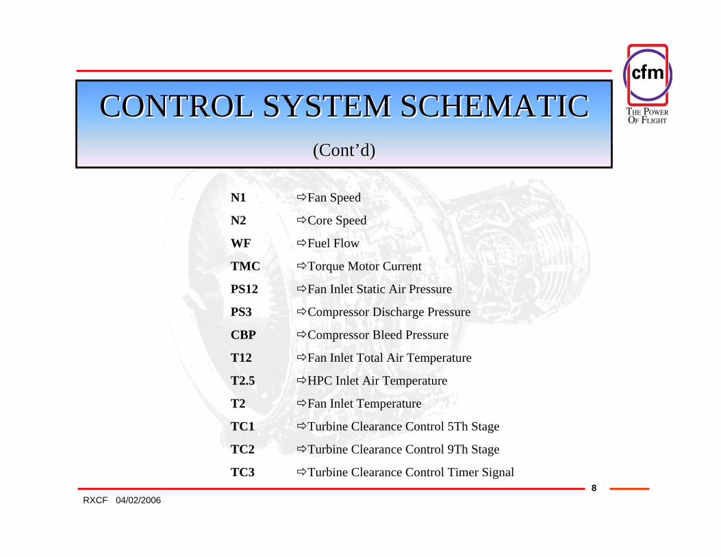
CONTROL SYSTEM SCHEMATIC CONTROL SYSTEM SCHEMATIC (Cont(Cont’’d)d)
N1 Fan Speed
N2 Core Speed
WF Fuel Flow
TMC Torque Motor Current
PS12 Fan Inlet Static Air Pressure
PS3 Compressor Discharge Pressure
CBP Compressor Bleed Pressure
T12 Fan Inlet Total Air Temperature
T2.5 HPC Inlet Air Temperature
T2 Fan Inlet Temperature
TC1 Turbine Clearance Control 5Th Stage
TC2 Turbine Clearance Control 9Th Stage
TC3 Turbine Clearance Control Timer Signal
THE POWER�OF FLIGHT
904/02/2006RXCF
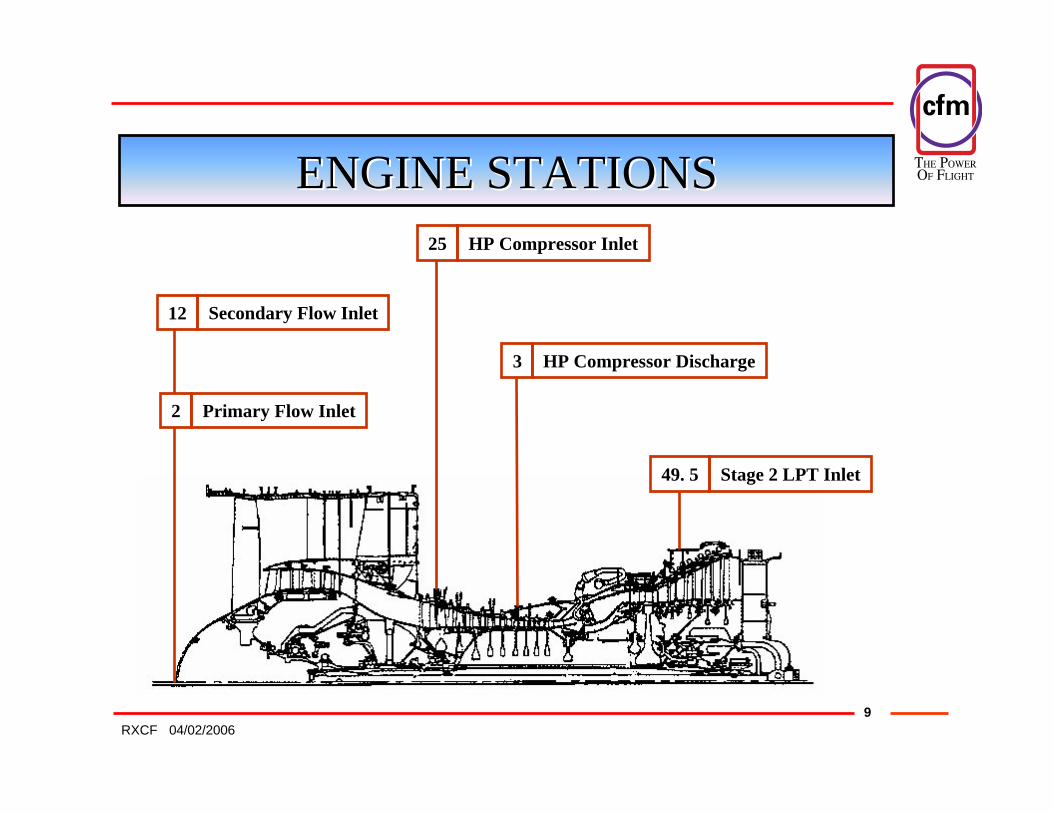
ENGINE STATIONSENGINE STATIONS
2 Primary Flow Inlet
12 Secondary Flow Inlet
25 HP Compressor Inlet
3 HP Compressor Discharge
49. 5 Stage 2 LPT Inlet
THE POWER�OF FLIGHT
1004/02/2006RXCF
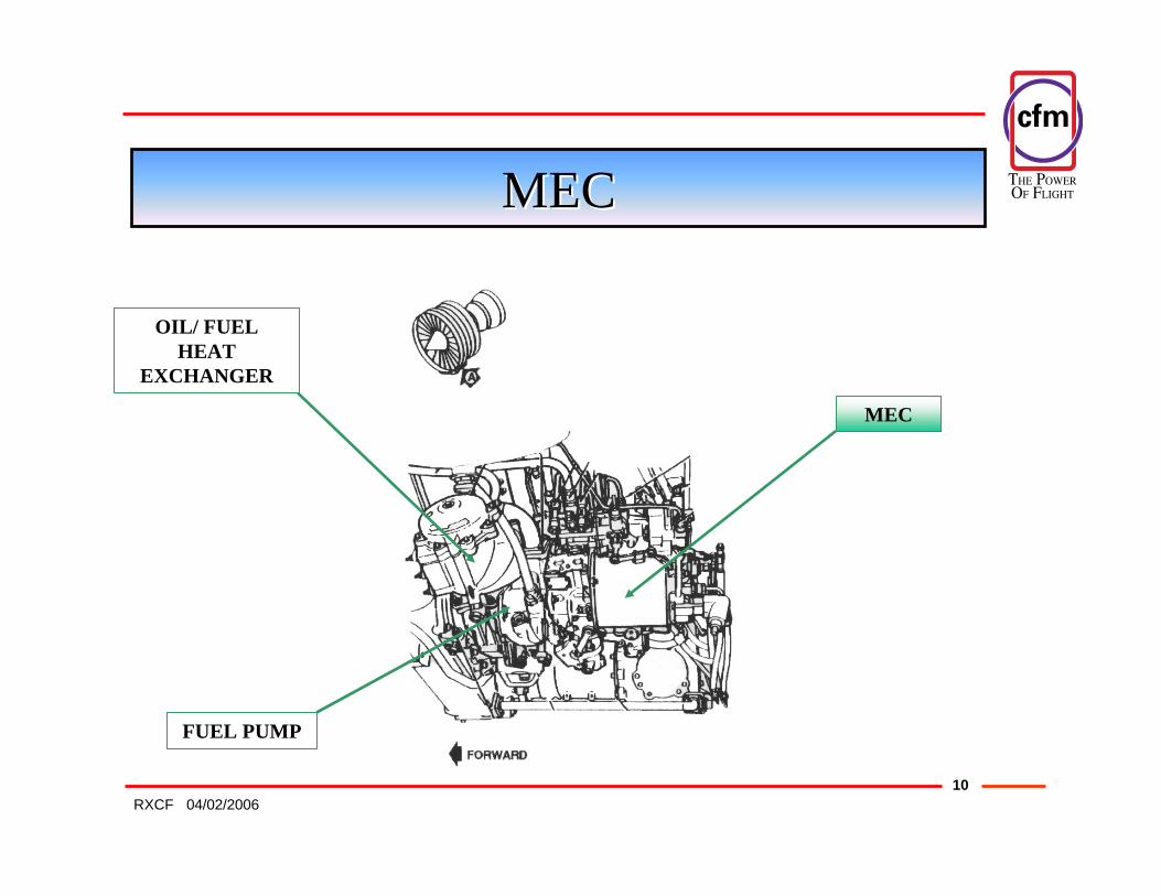
MECMEC
MEC
FUEL PUMP
OIL/ FUEL HEAT
EXCHANGER
THE POWER�OF FLIGHT
1104/02/2006RXCF
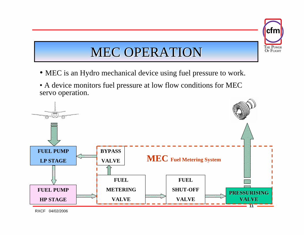
MECMEC OPERATIONOPERATION• MEC is an Hydro mechanical device using fuel pressure to work.• A device monitors fuel pressure at low flow conditions for MECservo operation.
FUEL
METERING
VALVEPRESSURISING PRESSURISING
VALVEVALVE
FUEL
SHUT-OFF
VALVE
BYPASS
VALVE
FUEL PUMP
HP STAGE
FUEL PUMP
LP STAGE MEC Fuel Metering System

THE POWER�OF FLIGHT
1204/02/2006RXCF
MECMEC PURPOSEPURPOSE• The MECMEC’’ss job is divided in 2 tasks:
MAIN TASKS:
ADDITIONAL TASKS:
–– Speed governing systemSpeed governing system–– Fuel limiting systemFuel limiting system–– Idling systemIdling system
–– VBVVBV
– VSVVSV
– HPTCCVHPTCCV
Control functions to optimise engine performance
THE POWER�OF FLIGHT
1304/02/2006RXCF
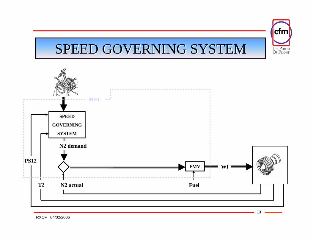
SPEED GOVERNING SYSTEMSPEED GOVERNING SYSTEM
SPEED
GOVERNING
SYSTEM
FMV Wf
N2 demand
N2 actualT2 Fuel
PS12
MEC

THE POWER�OF FLIGHT
1404/02/2006RXCF
FUEL LIMITING SYSTEMFUEL LIMITING SYSTEM
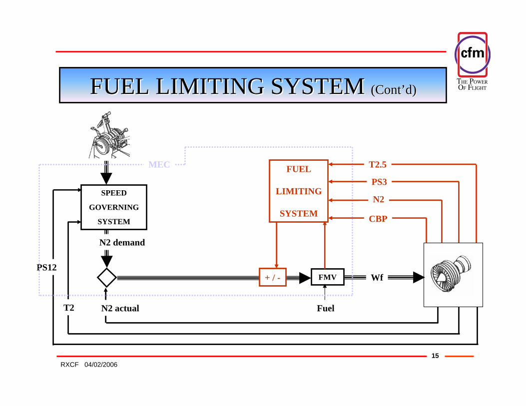
• During transient operation, the speed governing system could change the fuel flow beyond the safe limits.• The purpose of the fuel limiting system is to define and impose correct engine fuel flow limits during rapid transients:
ACCELERATIONS
DECELERATIONS
STARTS
THE POWER�OF FLIGHT
1504/02/2006RXCF
SPEED
GOVERNING
SYSTEM
FMV
Fuel
Wf
T2
N2 demand
N2 actual
FUEL
LIMITING
SYSTEM
PS12
MEC
FUEL LIMITING SYSTEM FUEL LIMITING SYSTEM (Cont(Cont’’d)d)
+ / -
N2
PS3
T2.5
CBP
THE POWER�OF FLIGHT
1604/02/2006RXCF
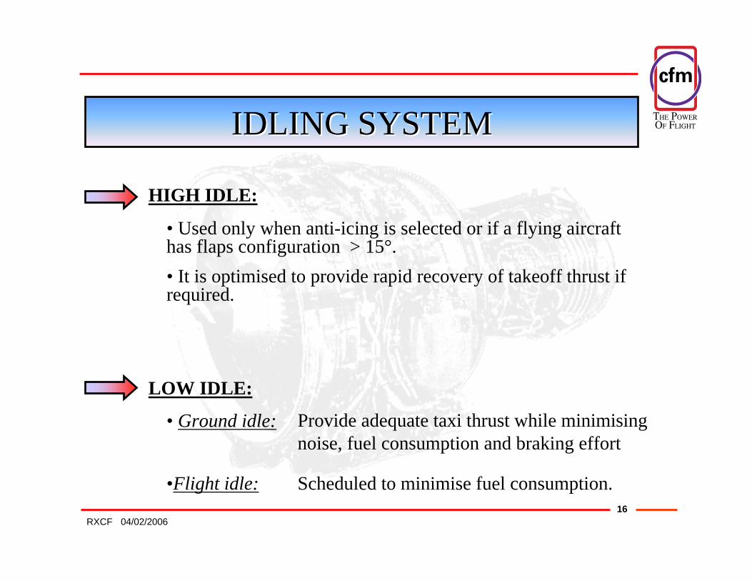
IDLING SYSTEMIDLING SYSTEM
HIGH IDLE:
LOW IDLE:
• Used only when anti-icing is selected or if a flying aircraft has flaps configuration > 15°.• It is optimised to provide rapid recovery of takeoff thrust if required.
• Ground idle:
•Flight idle:
Provide adequate taxi thrust while minimising noise, fuel consumption and braking effort
Scheduled to minimise fuel consumption.
THE POWER�OF FLIGHT
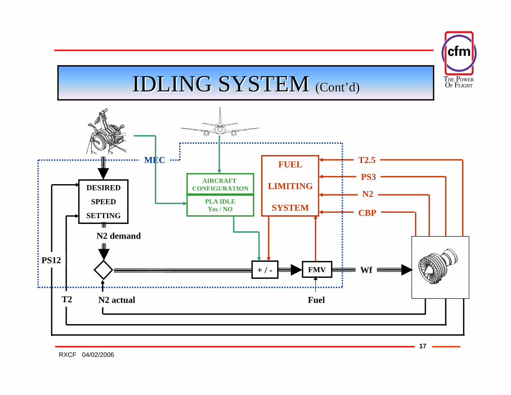
1704/02/2006RXCF
DESIRED
SPEED
SETTING
FMV
Fuel
Wf
T2
N2 demand
N2 actual
+ / -
FUEL
LIMITING
SYSTEM
PS3
N2
T2.5
CBP
PS12
MEC
PLA IDLEYes / NO
AIRCRAFT CONFIGURATION
IDLING SYSTEM IDLING SYSTEM (Cont(Cont’’d)d)
THE POWER�OF FLIGHT
1804/02/2006RXCF
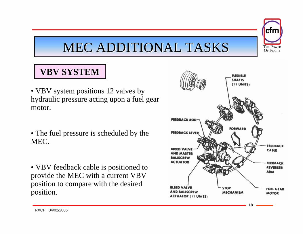
MECMEC ADDITIONAL TASKSADDITIONAL TASKS
VBVVBV SYSTEMSYSTEM
• VBV system positions 12 valves by hydraulic pressure acting upon a fuel gear motor.
• The fuel pressure is scheduled by the MEC.
• VBV feedback cable is positioned to provide the MEC with a current VBVposition to compare with the desired position.
THE POWER�OF FLIGHT
1904/02/2006RXCF
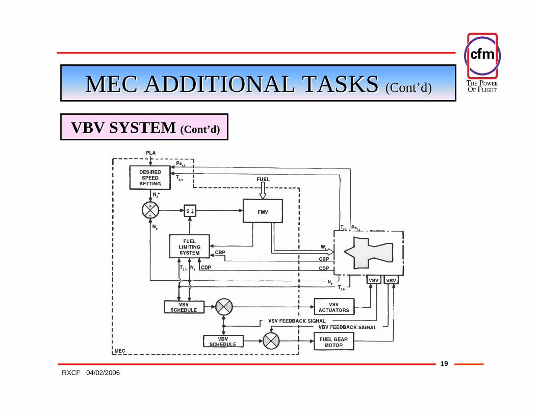
MECMEC ADDITIONAL TASKS ADDITIONAL TASKS (Cont(Cont’’d)d)
VBVVBV SYSTEM SYSTEM (Cont(Cont’’d)d)

THE POWER�OF FLIGHT
2004/02/2006RXCF
MECMEC ADDITIONAL TASKS ADDITIONAL TASKS (Cont(Cont’’d)d)
VBVVBV PURPOSEPURPOSE
As the Compressor is optimised for ratings close to maximum power engine operation has to be protected during deceleration or at low speed:
To re-establish a suitable mass flow VBV are installed on the contour of the primary airflow stream between booster and HPC to download booster exit.
Without VBV installed:At Deceleration or Low speed⇒ Booster Outlet Airflow ↓↓ much more than Booster Pressure Ratio⇒ LPC stall margin reduced
With VBV installed:At Deceleration or Low speed⇒ VBV fully open⇒ Booster Pressure Ratio ↓↓ but same Booster Outlet Airflow⇒ Plenty of LPC stall margin
THE POWER�OF FLIGHT
2104/02/2006RXCF
MECMEC ADDITIONAL TASKS ADDITIONAL TASKS (Cont(Cont’’d)d)
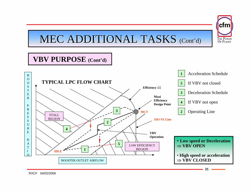
VBVVBV PURPOSE PURPOSE (Cont(Cont’’d)d)
Maxi EfficiencyDesign Point
ISO N1 Line
Efficiency ↓↓
BOOSTER OUTLET AIRFLOW
BOOSTER
PRESSURE
RATIO
LOW EFFICIENCYREGION1
2
3
4VBVOperation
Acceleration Schedule 1
2
3
4
• Low speed or Deceleration⇒ VBV OPEN
• High speed or acceleration⇒ VBV CLOSED
TYPICAL LPC FLOW CHART
5
5
Operating Line
Deceleration Schedule
If VBV not open
If VBV not closed
STALLREGION
IDLE
MCT

THE POWER�OF FLIGHT
2204/02/2006RXCF
MECMEC ADDITIONAL TASKS ADDITIONAL TASKS (Cont(Cont’’d)d)
VSVVSV SYSTEMSYSTEM
VSV system changes the angle of the HP Compressor IGV and N° 1,2 and 3 stator stages according to the MEC computation.MEC directs a resulting high pressure fuel flow to the dual VSVactuators.The actuators mechanically position the VSV.
A feedback cable provides the VSV position to the MEC.
A comparison is performed between schedule requirements and actual VSV position to determine the need to continue actuator control or not.

THE POWER�OF FLIGHT
2304/02/2006RXCF
MECMEC ADDITIONAL TASKS ADDITIONAL TASKS (Cont(Cont’’d)d)
VSVVSV SYSTEMSYSTEM (Cont(Cont’’d)d)

THE POWER�OF FLIGHT
2404/02/2006RXCF
MECMEC ADDITIONAL TASKS ADDITIONAL TASKS (Cont(Cont’’d)d)
VSVVSV SYSTEMSYSTEM (Cont(Cont’’d)d)

THE POWER�OF FLIGHT
2504/02/2006RXCF
IGV
ROTOR
VSV 1
Etc …
MECMEC ADDITIONAL TASKS ADDITIONAL TASKS (Cont(Cont’’d)d)
VSVVSV PURPOSEPURPOSE
IGV (Inlet Guide Vane)
ROTOR STAGE
VSV (3)
- VSV optimise HPC efficiency.- VSV improve stall margin for transient engine operations.
• The Compressor is optimised for ratings close to maximum power.• Engine operation has to be protected during deceleration or at low speed.• VSV system position HPC Stator Vanes to the appropriate angle of incidence.

THE POWER�OF FLIGHT
2604/02/2006RXCF
MECMEC ADDITIONAL TASKS ADDITIONAL TASKS (Cont(Cont’’d)d)
VSVVSV PURPOSE PURPOSE (Cont(Cont’’d)d)
COMPRESSOR OUTLET AIRFLOW
COMPRESSOR
PRESSURE
RATIO
LOW EFFICIENCYREGION
STALLREGION
Efficiency ↓↓
Maxi EfficiencyDesign Point
ISO N1 Line
VSVOperation
1
4
2
TYPICAL HPC FLOW CHARTAcceleration Schedule 1
2
3
4 Operating Line
Deceleration Schedule
If VSV not open
• Low speed or Deceleration⇒ VSV CLOSED
• High speed or acceleration⇒ VSV OPEN
3IDLE
MCT
MECMEC ADDITIONAL TASKS ADDITIONAL TASKS (Cont(Cont’’d)d)

THE POWER�OF FLIGHT
2704/02/2006RXCF
CLEARANCE CONTROLCLEARANCE CONTROL
• Operating tip clearance in the core engine are of primary importance. They determine:
Steady state efficiencies:⇒ Fuel consumption
Transient engine performance:⇒ Peak gas temperature⇒ Compressor stall margin
THE POWER�OF FLIGHT
2804/02/2006RXCF
CLEARANCE CONTROL CLEARANCE CONTROL (Cont(Cont’’d)d)
• Clearance Control in the CFM56 engine is accomplished by a combination of 3 mechanical designs:
Passive control:⇒ Using materials in the compressor aft case with low coefficient of thermal expansion.
Forced cooling:⇒ Using Low Pressure Booster discharge cooling air for compressor and turbine.
Automatic control:⇒ HPTCC VALVE and HPTCC TIMER are used to control the tip clearance between HPT blades and stationary tip shrouds.

THE POWER�OF FLIGHT
2904/02/2006RXCF
HPTCCVHPTCCV ACTUATIONACTUATION
• Automatic Control is using Bleed Air from 5Th and 9Th stages of HPC to either cool or heat the HPT shroud.
MEC HPTCC TIMER HPT SHROUD
AIR FROM
5Th
STAGE
AIR FROM
9Th
STAGE
AIRCRAFT ON THE
GROUNDYES / NO
N2 > 95 %YES / NO
HPTCCVALVE
THE POWER�OF FLIGHT
3004/02/2006RXCF
HPTCCVHPTCCV ACTUATION ACTUATION (Cont(Cont’’d)d)
• During flight:
- Air selection is determined by fuel pressure signals sent from the MEC to the TIMER.
- The TIMER sends fuel pressure signals without change to actuate the HPTCC VALVE.
- The selected bleed air is ducted to a manifold surrounding the HPT SHROUD.

THE POWER�OF FLIGHT
3104/02/2006RXCF
HPTCCVHPTCCV ACTUATION ACTUATION (Cont(Cont’’d)d)
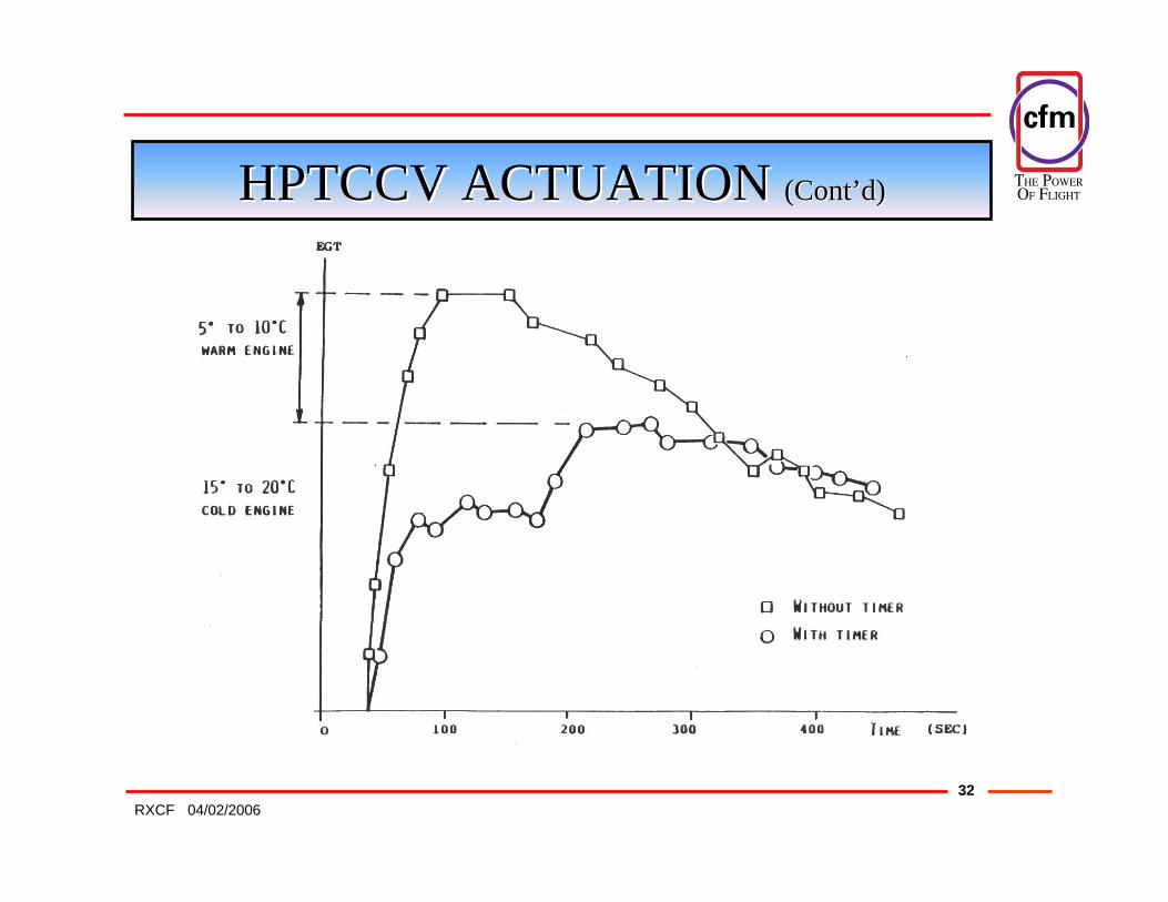
• During takeoff:
- The TIMER overrides the normal MEC operation of the valve.
- It is sequencing a transient air schedule over a specified time period to maintain a more nearly constant HPT blade tip clearance during the period of HPT Rotor/Stator thermal stabilisation.
- This maintain Turbine efficiency and decreases transient EGTovershoot.
- A lockout valve permits the TIMER to actuate only once per engine cycle. ( i.e. from start to shut down)
THE POWER�OF FLIGHT
3204/02/2006RXCF
HPTCCVHPTCCV ACTUATION ACTUATION (Cont(Cont’’d)d)
THE POWER�OF FLIGHT
3304/02/2006RXCF
HPTCCVHPTCCV ACTUATION ACTUATION (Cont(Cont’’d)d)
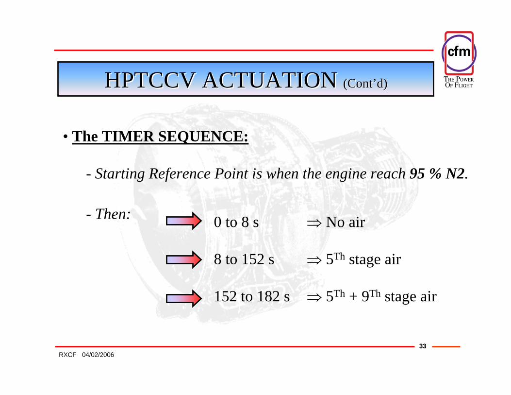
• The TIMER SEQUENCE:
- Starting Reference Point is when the engine reach 95 % N2.
0 to 8 s ⇒ No air
8 to 152 s ⇒ 5Th stage air
152 to 182 s ⇒ 5Th + 9Th stage air
- Then:

THE POWER�OF FLIGHT
3404/02/2006RXCF
HPTCCVHPTCCV ACTUATION ACTUATION (Cont(Cont’’d)d)
0 s 8 s 152 s 182 s
No Air 5+9Th stage Air5Th stage Air
NO TIMER TIMER
STATOR Ø
ROTOR Ø
CLEARANCE with TIMER
CLEARANCE without TIMER

THE POWER�OF FLIGHT
3504/02/2006RXCF
PMCPMC
INPUT POWER
INPUT SIGNALS:
N1, T12, PLA
OUTPUT SIGNALS:
FOR MEC TORQUE MOTOR
MONITOR CONNECTION
COCKPIT SW:
PMC On / Off
PS12

THE POWER�OF FLIGHT
3604/02/2006RXCF
PMCPMC PURPOSEPURPOSE
• In a high bypass engine, total thrust is more accurately controlled by controlling N1 speed.
FAN is 80% of the POWER !FAN is 80% of the POWER !
This is accomplished byvarying N2 speed
to reach theaccurate N1 speed.
THE POWER�OF FLIGHT
3704/02/2006RXCF
PMCPMC OPERATIONOPERATION
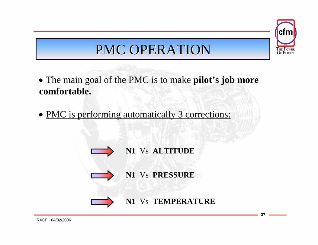
• The main goal of the PMC is to make pilot’s job morecomfortable.
• PMC is performing automatically 3 corrections:
N1 Vs ALTITUDE
N1 Vs PRESSURE
N1 Vs TEMPERATURE
THE POWER�OF FLIGHT
3804/02/2006RXCF
N1N1 Vs Vs ALTITUDEALTITUDE
PMCPMC OPERATION OPERATION (Cont(Cont’’d)d)
N1
Z
STEADYTHRUST %
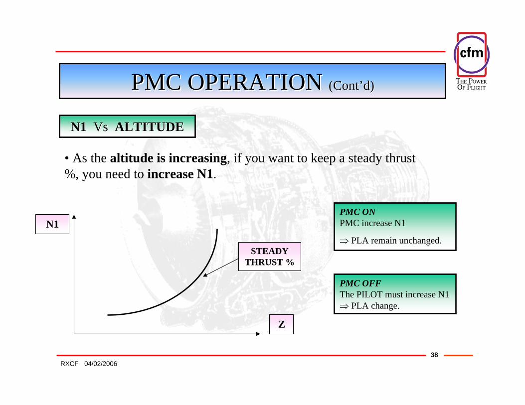
• As the altitude is increasing, if you want to keep a steady thrust %, you need to increase N1.
PMC OFFThe PILOT must increase N1⇒ PLA change.
PMC ONPMC increase N1
⇒ PLA remain unchanged.
THE POWER�OF FLIGHT
3904/02/2006RXCF
PMCPMC OPERATION OPERATION (Cont(Cont’’d)d)
N1N1 Vs Vs PRESSUREPRESSURE
N1
P
STEADYTHRUST %
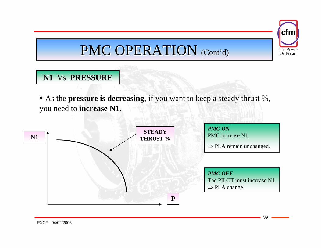
• As the pressure is decreasing, if you want to keep a steady thrust %, you need to increase N1.
PMC ONPMC increase N1
⇒ PLA remain unchanged.
PMC OFFThe PILOT must increase N1⇒ PLA change.
THE POWER�OF FLIGHT
4004/02/2006RXCF
PMCPMC OPERATION OPERATION (Cont(Cont’’d)d)
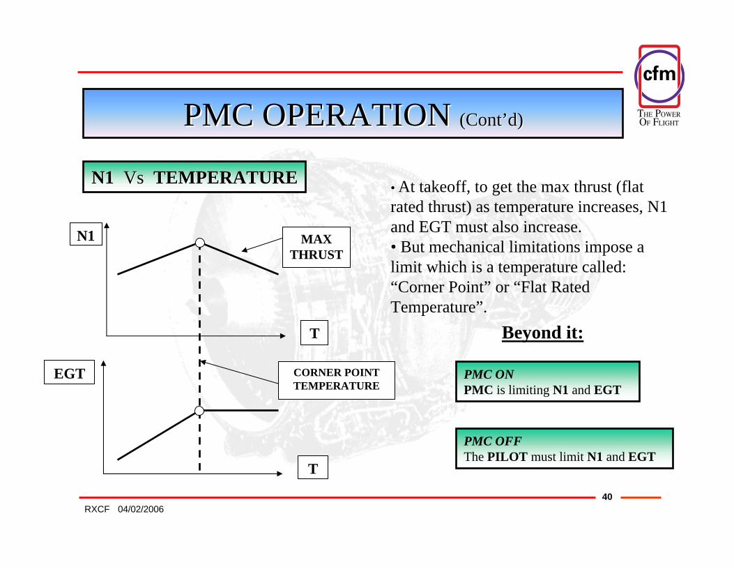
N1N1 Vs Vs TEMPERATURETEMPERATURE
N1 MAX THRUST
EGT
T
CORNER POINTTEMPERATURE
T
• At takeoff, to get the max thrust (flat rated thrust) as temperature increases, N1 and EGT must also increase.• But mechanical limitations impose a limit which is a temperature called: “Corner Point” or “Flat Rated Temperature”.
Beyond it:
PMC ONPMC is limiting N1 and EGT
PMC OFFThe PILOT must limit N1 and EGT
THE POWER�OF FLIGHT
4104/02/2006RXCF
PMCPMC OPERATION OPERATION (Cont(Cont’’d)d)
• PMC efficiency start at 50% N1 and is fully efficient at or above 70% N1.
• PMC trims MEC to maintain the commanded thrust
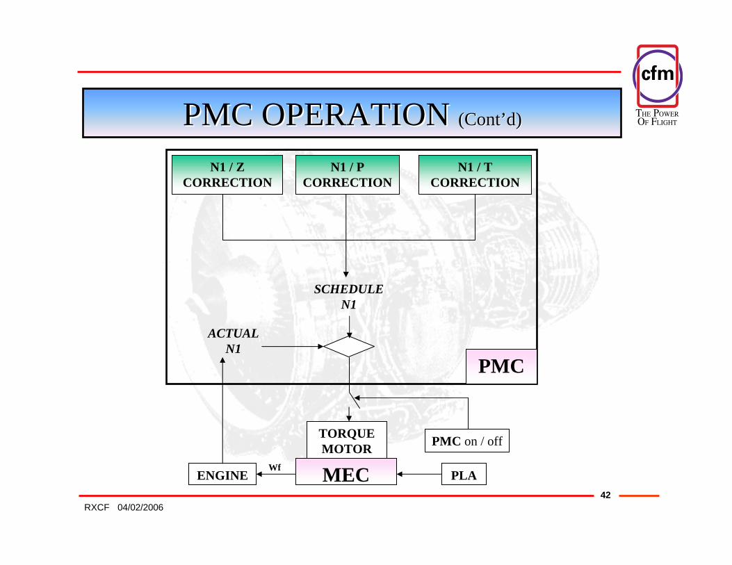
• Schedule N1 is compared to actual N1.The error signalgenerates from the PMC an Output Current (TMC) to a torque motor mounted on the MEC.The torque motor changes Fuel Flow (Wf).
N2 and N1 change.
THE POWER�OF FLIGHT
4204/02/2006RXCF
PMCPMC OPERATION OPERATION (Cont(Cont’’d)d)
N1 / ZCORRECTION
N1 / PCORRECTION
N1 / TCORRECTION
SCHEDULE N1
ENGINE MEC
TORQUE MOTOR
ACTUAL N1
PMC
PLA
PMC on / off
Wf

THE POWER�OF FLIGHT
4304/02/2006RXCF
THE ENDTHE END
THANKS FOR YOURTHANKS FOR YOURATTENTION !ATTENTION !