Embed Size (px)
DESCRIPTION
Project on Fuel Valve
Citation preview

AUTO TURNING FUEL VALVE
Department of Mechanical Engineering
PROJECT WORK 2010-2011
CONTENTS
CONTENTS
1. SYNOPSIS.
2. INTRODUCTION.
3. MAIN PARTS.
4. DESCRIPTION OF PARTS.
5. PRINCIPLE OF OPERATION.
6. ADVANTAGES & APPLICATIONS.
7. PROJECT SCHDULE
8. COST ESTIMATION
9. BIBLIONGRAPHY.
10.CONCLUSION.
11.PHOTOS.
INTRODUCTION:
A motorcycle (also called a motorbike, bike, or cycle) is a single-track,
engine-powered, two-wheeled motor vehicle. Motorcycles vary considerably
depending on the task for which they are designed, such as long distance travel,
navigating congested, cruising, sport and racing, or off-road conditions.
Motorcycles are one of the most affordable forms of motorized transport in
many parts of the world and, for most of the world's population; they are also the
most common type of motor vehicle. There are around 200 million motorcycles
(including mopeds, motor scooters and other powered two and three-wheelers) in
use worldwide, or about 33 motorcycles per 1000 people. This compares to around
590 million cars, or about 91 per 1000 people. Most of the motorcycles, 58%, are
in the developing countries of Asia—Southern and Eastern Asia, and the Asia
Pacific countries, excluding Japan—while 33% of the cars (195 million) are
concentrated in the United States and Japan. As of 2002, India with an estimated
37 million motorcycles/mopeds was home to the largest number of motorized two
wheelers in the world. China came a close second with 34 million
motorcycles/mopeds.

HISTORY:
The first internal combustion, petroleum fueled motorcycle was
the Petroleum Reitwagen. It was designed and built by the German inventors
Gottlieb Daimler and Wilhelm Maybach in Bad Cannstatt, Germany in 1885. This
vehicle was unlike either the safety bicycles or the boneshaker bicycles of the era
in that it had zero degrees of steering axis angle and no fork offset, and thus did not
use the principles of bicycle developed nearly 70 years earlier. Instead, it relied on
two outrigger wheels to remain upright while turning. The inventors called their
invention the Reitwagen ("riding car"). It was designed as an expedient tested for
their new engine, rather than a true prototype vehicle. Many authorities who
exclude steam powered, electric or diesel two-wheelers from the definition of a
motorcycle, credit the Daimler Reitwagen as the world's first motorcycle.
If a two-wheeled vehicle with steam propulsion is considered a motorcycle,
then the first was the French velocipede of 1868. This was followed by the
American Roper steam velocipede of 1869, built by Sylvester H. Roper Roxbury,
Massachusetts. Roper demonstrated his machine at fairs and circuses in the eastern
U.S. in 1867, and built a total of 10 examples.
In 1894, Hildebrand & Wolfmüller became the first series production motorcycle
and the first to be called a motorcycle (German: Motorrad). In the early period of

motorcycle history, many producers of bicycles adapted their designs to
accommodate the new internal combustion engine. As the engines became more
powerful and designs outgrew the bicycle origins, the number of motorcycle
producers increased.
Until World War I, the largest motorcycle manufacturer in the world
was Indian, producing over 20,000 bikes per year. By 1920, this honor went
to Harley-Davidson, with their motorcycles being sold by dealers in 67 countries.
By the late 1920s or early 1930s, DKW took over as the largest manufacturer.
After World War II, the BSA Group became the largest producer of
motorcycles in the world, producing up to 75,000 bikes per year in the 1950s. The
German company NSU held the position of largest manufacturer from 1955 until
the 1970s.
In the 1950s, streamlining began to play an increasing part in the
development of racing motorcycles and the "dustbin fairing" held out the
possibility of radical changes to motorcycle design. NSU and Moto Guzzi were in
the vanguard of this development, both producing very radical designs well ahead
of their time.[25] NSU produced the most advanced design, but after the deaths of
four NSU riders in the 1954–1956 seasons, they abandoned further development
and quit Grand Prix motorcycle racing. Moto Guzzi produced competitive race
machines, and by 1957 nearly all the Grand Prix races were being won by

streamlined machines. The following year, 1958, full enclosure fairings were
banned from racing by the FIM in the light of the safety concerns.
From the 1960s through the 1990s, small two-stroke motorcycles were popular
worldwide, partly as a result of East German Walter Kaaden's engine work in the
1950s.
Today, the motorcycle industry is mainly dominated by Japanese companies
such as Honda, Kawasaki, Suzuki, and Yamaha, although Harley-
Davidson and BMW continue to be popular and supply considerable markets.
Other major manufacturers include Piaggio group of Italy,
TM, Triumph and Ducati.
In addition to the large capacity motorcycles, there is a large market in
smaller capacity (less than 300 cc) motorcycles, mostly concentrated in Asian and
African countries. An example is the 1958 Honda Super Cub, which went on to
become the biggest selling vehicle of all time, with its 60 millionth unit produced
in April 2008. Today, this area is dominated by mostly Indian
companies with Hero Honda emerging as the world's largest manufacturer of two
wheelers. Other major producers are Bajaj and TVS Motors. For example,
its Splendor model has sold more than 8.5 million to date.

MAIN PARTS
MAIN PARTS
Solenoid Valve
Ignition Switch
Battery
Connecting houses.

SOLENOID VALVE:
A solenoid valve is an electromechanical valve for use with liquid or gas.
The valve is controlled by an electric current through a solenoid: in the case of a
two-port valve the flow is switched on or off; in the case of a three-port valve, the
outflow is switched between the two outlet ports. Multiple solenoid valves can be
placed together on a manifold.
Solenoid valves are the most frequently used control elements in fluidics.
Their tasks are to shut off, release, dose, distribute or mix fluids. They are found in
many application areas. Solenoids offer fast and safe switching, high reliability,
long service life, good medium compatibility of the materials used, low control
power and compact design.
Besides the plunger-type actuator which is used most frequently, pivoted-armature
actuators and rocker actuators are also used.
ELECTROMECHANICAL SOLENOIDS:
Electromechanical solenoids consist of an electromagnetically inductive
coil, wound around a movable steel or iron slug (termed the armature). The coil is
shaped such that the armature can be moved in and out of the center, altering the

coil's inductance and thereby becoming an electromagnet. The armature is used to
provide a mechanical force to some mechanism (such as controlling a pneumatic
valve). Although typically weak over anything but very short distances, solenoids
may be controlled directly by a controller circuit, and thus have very low reaction
times.
The force applied to the armature is proportional to the change in inductance
of the coil with respect to the change in position of the armature, and the current
flowing through the coil (see Faraday's law of induction). The force applied to the
armature will always move the armature in a direction that increases the coil's
inductance.
Electromechanical solenoids are commonly seen in electronic paintball
markers, pinball machines, dot matrix printers and fuel injectors.
ROTARY SOLENOID:
The rotary solenoid is an electromechanical device used to rotate a
ratcheting mechanism when power is applied. These were used in the 1950s for
rotary snap-switch automation in electromechanical controls. Repeated actuation of
the rotary solenoid advances the snap-switch forward one position. Two rotary
actuators on opposite ends of the rotary snap-switch shaft, can advance or reverse
the switch position.

The rotary solenoid has a similar appearance to a linear solenoid, except that
the core is mounted in the center of a large flat disk, with two or three inclined
grooves cut into the underside of the disk. These grooves align with slots on the
solenoid body, with ball bearings in the grooves.
When the solenoid is activated, the core is drawn into the coil, and the disk rotates
on the ball bearings in the grooves as it moves towards the coil body. When power
is removed, a spring on the disk rotates it back to its starting position, also pulling
the core out of the coil.
The rotary solenoid was invented in 1944 by George H. Leland, of Dayton,
Ohio, to provide a more reliable and shock/vibration tolerant release mechanism
for air-dropped bombs. Previously used linear (axial) solenoids were prone to
inadvertent releases. U.S. Patent number 2,496,880 describes the electromagnet
and inclined raceways that are the basis of the invention. Leland's engineer, Earl
W. Kerman, was instrumental in developing a compatible bomb release shackle
that incorporated the rotary solenoid.
HYDRAULIC SOLENOID VALVES:
Hydraulic solenoid valves are in general similar to pneumatic solenoid
valves except that they control the flow of hydraulic fluid (oil), often at around
3000 psi (210 bar, 21 MPa, 21 MN/m²). Hydraulic machinery uses solenoids to

control the flow of oil to rams or actuators to (for instance) bend sheets of titanium
in aerospace manufacturing. Solenoid-controlled valves are often used in irrigation
systems, where a relatively weak solenoid opens and closes a small pilot valve,
which in turn activates the main valve by applying fluid pressure to a piston or
diaphragm that is mechanically coupled to the main valve. Solenoids are also in
everyday household items such as washing machines to control the flow and
amount of water into the drum.
PNEUMATIC SOLENOID VALVE:
A pneumatic solenoid valve is a switch for routing air to any pneumatic
device, usually an actuator, allowing a relatively small signal to control a large
device. It is also the interface between electronic controllers and pneumatic
systems.
ROTARY VOICE COIL:
This is a rotational version of a solenoid. Typically the fixed magnet is on
the outside, and the coil part moves in an arc controlled by the current flow
through the coils. Rotary voice coils are widely employed in devices such as disk
drives


TYPES OF SOLENOID VALVE:
Many variations are possible on the basic, one way, one solenoid valve
described above:
one or two solenoid valves;
direct current or alternating current powered;
different number of ways and positions
COMMON USES:
Solenoid valves are used in fluid power pneumatic and hydraulic systems, to
control cylinders, fluid power motors or larger industrial valves.
Automatic irrigation sprinkler systems also use solenoid valves with an
automatic controller. Domestic washing machines and dishwashers use solenoid
valves to control water entry to the machine. In the paintball industry, solenoid
valves are usually referred to simply as "solenoids." They are commonly used to
control a larger valve used to control the propellant (usually compressed air or
CO2). In the industry, "solenoid" may also refer to an
electromechanical solenoid commonly used to actuate a sear.
Besides controlling the flow of air and fluids solenoids are used in
pharmacology experiments, especially for patch-clamp, which can control the
application of agonist or antagonist.

BATTERY:
It is a lead- battery. The bayberry is consider as the most important
component of the MINIATURE MODEL OF SOLAR CAR . The battery has a
12V capacity. The battery is rested on the frame.
In isolated systems away from the grid, batteries are used for storage of
excess solar energy converted into electrical energy. The only exceptions are
isolated sunshine load such as irrigation pumps or drinking water supplies for
storage. In fact for small units with output less than one kilowatt. Batteries seem
to be the only technically and economically available storage means. Since both
the photo-voltaic system and batteries are high in capital costs.
It is necessary that the overall system be optimized with respect to available
energy and local demand pattern. To be economically attractive the storage of
solar electricity requires a battery with a particular combination of properties:
(1) Low cost
(2) Long life
(3) High reliability
(4) High overall efficiency
(5) Low discharge

(6) Minimum maintenance
(A) Ampere hour efficiency
(B) Watt hour efficiency
We use lead acid battery for storing the electrical energy from the solar
panel for lighting the street and so about the lead acid cells are explained below.
LEAD-ACID WET CELL:
Where high values of load current are necessary, the lead-acid cell is the
type most commonly used.
The electrolyte is a dilute solution of sulfuric acid (H₂SO₄). In the
application of battery power to start the engine in an auto mobile, for example, the
load current to the starter motor is typically 200 to 400A. One cell has a nominal
output of 2.1V, but lead-acid cells are often used in a series combination of three
for a 6-V battery and six for a 12-V battery.
The lead acid cell type is a secondary cell or storage cell, which can be
recharged. The charge and discharge cycle can be repeated many times to restore
the output voltage, as long as the cell is in good physical condition. However, heat
with excessive charge and discharge currents short ends the useful life to about 3 to
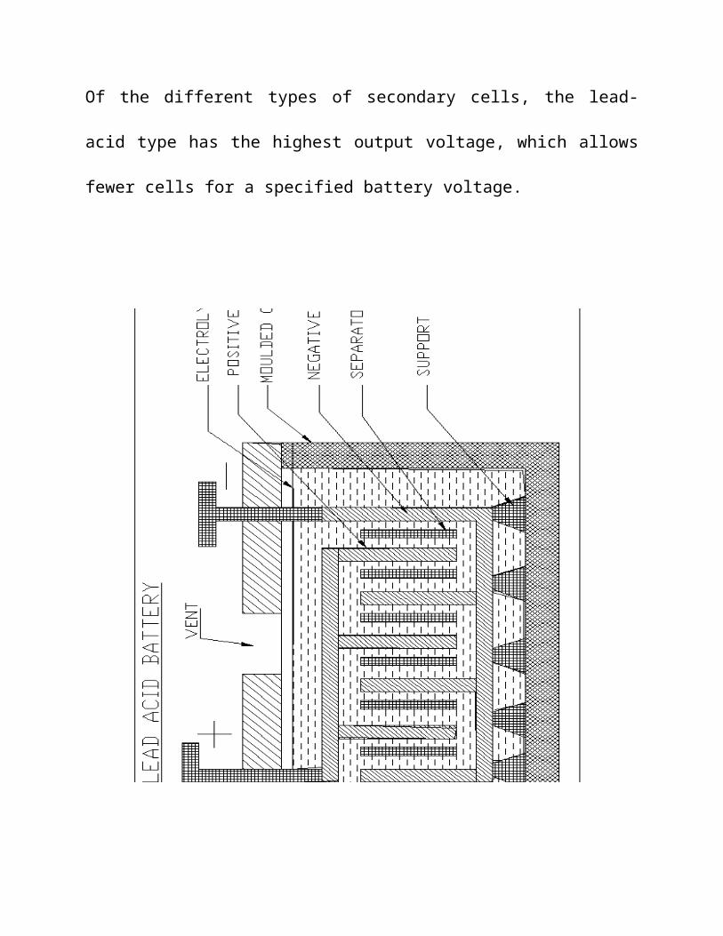
5 years for an automobile battery. Of the different types of secondary cells, the

lead-acid type has the highest output voltage, which allows fewer cells for a
specified battery voltage.

CONSTRUCTION:
Inside a lead-acid battery, the positive and negative electrodes consist of a
group of plates welded to a connecting strap. The plates are immersed in the
electrolyte, consisting of 8 parts of water to 3 parts of concentrated sulfuric acid.
Each plate is a grid or framework, made of a lead-antimony alloy. This
construction enables the active material, which is lead oxide, to be pasted into the
grid. In manufacture of the cell, a forming charge produces the positive and
negative electrodes. In the forming process, the active material in the positive
plate is changed to lead peroxide (pbo₂). The negative electrode is spongy lead
(pb).
Automobile batteries are usually shipped dry from the manufacturer. The
electrolyte is put in at the time of installation, and then the battery is charged to
from the plates. With maintenance-free batteries, little or no water need be added
in normal service. Some types are sealed, except for a pressure vent, without
provision for adding water.
The construction parts of battery are shown in figure.

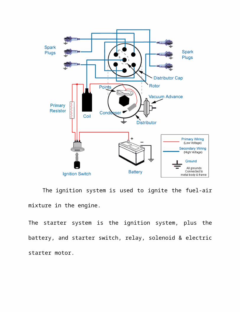
IGNITION SWITCH:
An Ignition (or starter) switch is an switch in the control system of an
internal combustion engine vehicle that activates the main electrical systems for
the vehicle. Besides providing power to the ignition system components (the starter
solenoid and ignition related components such as the engine control unit, spark coil
and distributor) it also usually switches on power to many "accessories" (radio,
power windows, etc).

The ignition system is used to ignite the fuel-air mixture in the engine.
The starter system is the ignition system, plus the battery, and starter switch, relay,
solenoid & electric starter motor.
The ignition switch usually requires a key be inserted that works a lock built
into the switch mechanism. It is frequently combined with the starter switch which
activates the starter motor.

FUEL TANK

PRINCIPLE OF OPERATION:
A solenoid valve has two main parts: the solenoid and the valve. The
solenoid converts electrical energy into mechanical energy which, in turn, opens or
closes the valve mechanically. A direct acting valve has only a small flow circuit,
shown within section E of this diagram (this section is mentioned below as a pilot
valve). This diaphragm piloted valve multiplies this small flow by using it to
control the flow through a much larger orifice.
Solenoid valves may use metal seals or rubber seals, and may also have
electrical interfaces to allow for easy control. A spring may be used to hold the
valve opened or closed while the valve is not activated.
The diagram to the right shows the design of a basic valve. At the top figure
is the valve in its closed state. The water under pressure enters at A. B is an elastic
diaphragm and above it is a weak spring pushing it down. The function of this
spring is irrelevant for now as the valve would stay closed even without it. The
diaphragm has a pinhole through its center which allows a very small amount of
water to flow through it. This water fills the cavity C on the other side of the
diaphragm so that pressure is equal on both sides of the diaphragm. While the
pressure is the same on both sides of the diaphragm, the force is greater on the
upper side which forces the valve shut against the incoming pressure. In the figure,
the surface being acted upon is greater on the upper side which results in greater

force. On the upper side the pressure is acting on the entire surface of the
diaphragm while on the lower side it is only acting on the incoming pipe. These
results in the valve being securely shut to any flow and, the greater the input
pressure, the greater the shutting force will be.
In the previous configuration the small conduit D was blocked by a pin
which is the armature of the solenoid E and which is pushed down by a spring. If
the solenoid is activated by drawing the pin upwards via magnetic force from the
solenoid current, the water in chamber C will flow through this conduit D to the
output side of the valve. The pressure in chamber C will drop and the incoming
pressure will lift the diaphragm thus opening the main valve. Water now flows
directly from A to F.
When the solenoid is again deactivated and the conduit D is closed again, the
spring needs very little force to push the diaphragm down again and the main valve
closes. In practice there is often no separate spring, the elastomeric diaphragm is
molded so that it functions as its own spring, preferring to be in the closed shape.
From this explanation it can be seen that this type of valve relies on a differential
of pressure between input and output as the pressure at the input must always be
greater than the pressure at the output for it to work. Should the pressure at the
output, for any reason, rise above that of the input then the valve would open
regardless of the state of the solenoid and pilot valve.

In some solenoid valves the solenoid acts directly on the main valve. Others use a
small, complete solenoid valve, known as a pilot, to actuate a larger valve. While
the second type is actually a solenoid valve combined with a pneumatically
actuated valve, they are sold and packaged as a single unit referred to as a solenoid
valve. Piloted valves require much less power to control, but they are noticeably
slower. Piloted solenoids usually need full power at all times to open and stay
open, where a direct acting solenoid may only need full power for a short period of
time to open it, and only low power to hold it. Thus the fuel flow is also controlled
by the same method.
ADVANTAGES:
Compact in size
Less maintenance cost
Gives good reliability
Less economic cost
APPLICATION:
Applied in all automobile vehicles.

PROJECT SCHEDULE
S1.No Description Periods
1 Deciding of title 3Weeks
2 Library Study 2Weeks
3 Material collection 3Weeks
4 Fabrication 3Weeks
5 Assembly 1Weeks

COST ESTIMATION
The cost estimation of out project is
SL. NO. NAME OF THE PARTS MATERIAL QUANTITY COST
1 Fuel tank - 1 2500
2 Direction Control Valve - 1 2000
3 Battery(12v) - 1 1500
4 Connecting Tube Polyurethane 1 meter 25
Total cost 6,025/-Rs

CONCLUSION
The aim of this project work under taken in our polytechnic college is
apart from improving the student’s practical knowledge in mechanical field and
also to manufacturing suitable units for doing a job in a scientific way.
In fabricating this project we gained invaluable technical
knowledge regarding, material solution, planning the project, group efforts in
achieving targets, cost estimation and also gained confidence in doing works.
However in completing the project we felt the aims of the
implementation of project work in our college.
BIBLIOGRAPHY
Automobile Technology - Kirpaul Singh
Automobile Engineering - Joseph Aeitner
Automobile Maintenance - R.B.Gupta
www.wikipedia.com
www.howstuffworks.com
www.gizmag.com

PHOTOGRAPHY