Embed Size (px)
Citation preview
GISFI TR SP.1xx V1.0.0 (20xx-xx)Technical Report
Global ICT Standardisation Forum for India;Technical Working Group Security and Privacy;
GSM Base Station Subsystem Security Requirements; (Draft)
The present document has been developed within GISFI and may be further elaborated for the purposes of GISFI.

GISFI
GISFI
GISFI office addressSuite 303, 3rd Floor, Tirupati Plaza, Plot No. 4, Sector 11, Dwarka, New Delhi-110075, India
Tel.: +91-11-47581800 Fax: +91-11-47581801
Internethttp://www.gisfi.org
E-mail: [email protected]
Copyright Notification
No part may be reproduced except as authorized by written permission.The copyright and the foregoing restriction extend to reproduction in all media.
© 2011, GISFI All rights reserved.
GISFI TR SP.1xx V1.0.0 (20xx-xx)2Draft
Contents
Foreword.....................................................................................................................................................5
Introduction.................................................................................................................................................6
1 Scope.................................................................................................................................................7
2 References.........................................................................................................................................8
3 Definitions, symbols and abbreviations............................................................................................93.1 Definitions...................................................................................................................................................93.2 Abbreviations............................................................................................................................................12
4 General............................................................................................................................................144.1. Functionality of the BSS...........................................................................................................................144.2. Standards based GSM network architecture showing the interfaces of BSS............................................154.2.1 The Access Network (AN) entities.....................................................................................................164.2.1.1 The Base Station System (BSS).....................................................................................................164.2.1.2 Base Station Controller (BSC).......................................................................................................164.2.1.3 Base Transceiver Station (BTS)....................................................................................................164.2.1.4 The Mobile Station (MS)...............................................................................................................164.2.2 The Core Network (CN) Entities........................................................................................................164.2.2.1 The Home Location Register (HLR).............................................................................................164.2.2.2 The Authentication Centre (AuC)..................................................................................................174.2.2.3 The Visitor Location Register (VLR)............................................................................................174.2.2.4 The Equipment Identity Register (EIR).........................................................................................174.2.3 PLMN basic interfaces.......................................................................................................................174.2.3.1 Interfaces between Mobile Station and the Fixed Infrastructure...................................................184.2.3.1.1 Interface between Mobile Station and Base Station System (Um-interface)..........................184.2.3.2 Interface between the Core Network and the Access Network.....................................................184.2.3.2.1 Interface between the MSC and Base Station System (A-interface)......................................184.2.3.3 Interfaces internal to the Access Network.....................................................................................184.2.3.3.1 Interface between BSC and BTS (Abis-interface)..................................................................184.2.3.4 Interfaces internal to the Core Network.........................................................................................184.2.3.4.1 Interface between the MSC server and its associated VLR (B-interface)...............................184.2.3.4.2 Interface between the HLR and the MSC server (C-interface)................................................184.2.3.4.3 Interface between the HLR and the VLR (D-interface)...........................................................194.2.3.4.4 Interface between MSC servers or MSC server and IP-SM-GW (E-interface).....................194.2.3.4.5 Interface between MSC server and EIR (F-interface)............................................................194.2.3.4.6 Interface between VLRs (G-interface)...................................................................................194.2.3.4.7 Interface between HLR/HSS and AuC (H-Interface)............................................................194.3. Various practical configurations of BSS deployment...............................................................................204.4. Protocols in BSS.......................................................................................................................................214.4.1 Interface between BSS and MSC (A – interface)................................................................................214.4.2 Interface between BSC and BTS (Abis-interface)..............................................................................22
5 Security Threats and Requirements................................................................................................235.1 General security requirements...................................................................................................................235.2 Requirements from certification bodies etc. if available, e.g. GCF..........................................................235.3 Security requirements from specifications [11, 12]..................................................................................245.3.1 Subscriber identity confidentiality (IMSI related)..............................................................................245.3.1.1 Functional requirements................................................................................................................245.3.2 Subscriber identity authentication.......................................................................................................245.3.2.1 Functional requirements................................................................................................................245.3.2.1.1 Authentication procedure.........................................................................................................245.3.2.1.2 Key management......................................................................................................................255.3.3 User data confidentiality on physical connections (Voice and Non voice).........................................275.3.3.1 Functional Requirement.................................................................................................................275.3.4 Connectionless user data confidentiality.............................................................................................275.3.5 Signalling information element confidentiality...................................................................................27
GISFI
GISFI TR SP.1xx V1.0.0 (20xx-xx)3Draft
5.3.5.1 Functional requirement..................................................................................................................275.3.5.1.1 The ciphering method..............................................................................................................285.3.5.1.2 The key setting.........................................................................................................................285.3.5.1.3 The starting of the enciphering and deciphering processes.....................................................285.3.5.1.4 The synchronization.................................................................................................................295.3.6 Algorithm A5: Ciphering/deciphering algorithm................................................................................305.3.6.1 Negotiation of A5 algorithm..........................................................................................................305.3.6.2 Support of A5 Algorithms in MS..................................................................................................305.3.6.3 Support of A5 Algorithms in BSS.................................................................................................305.3.6.4 Overview of A5 Algorithm............................................................................................................315.3.6 Algorithm A3: Key Generation...........................................................................................................315.3.6.1 Purpose...........................................................................................................................................315.3.6.2 Implementation and operational requirements..............................................................................325.3.7 Algorithm A8: Key Generation...........................................................................................................325.3.7.1 Purpose...........................................................................................................................................325.3.7.2 Implementation and operational requirements..............................................................................325.4 Threats and requirements from threats................................................................................................335.4.1 Unauthorised access to data.................................................................................................................345.4.2 Threats to integrity..............................................................................................................................355.4.3 Denial of service attacks......................................................................................................................355.4.4 Unauthorised access to services..........................................................................................................355.4.5 Protocol layers and threats...................................................................................................................365.4.6 Threats based on deployment / location..............................................................................................365.4.7 Threats found in open literature..........................................................................................................375.4.8 Requirements on security of GSM services addressed by standard....................................................38
A.1 Heading levels in an annex.............................................................................................................40
Annex B: Change history:.........................................................................................................................41
GISFI
GISFI TR SP.1xx V1.0.0 (20xx-xx)4Draft

ForewordThis Technical Report has been produced by GISFI.
The contents of the present document are subject to continuing work within the Technical Working Group (TWG) and may change following formal TWG approval. Should the TWG modify the contents of the present document, it will be re-released by the TWG with an identifying change of release date and an increase in version number as follows:
Version x.y.z
where:
x the first digit shows the release to which the document belongs
y the second digit is incremented for all changes of substance, i.e. technical enhancements, corrections, updates, etc.
z the third digit is incremented when editorial only changes have been incorporated in the document.
GISFI
GISFI TR SP.1xx V1.0.0 (20xx-xx)5Draft
IntroductionThe GSM standard for mobile communication supports various security features that protect the user equipment as well as the network elements from threats. However, the standard exposes a number of security risks which may be exploited by attackers. Network products based on the GSM standard may also expose risks due to implementation or deployment considerations. Security testing of the network elements can reveal these risks and help vendors and operators to address these issues effectively. This technical report details various aspects of GSM security as per applicable standards and threats faced by the network.
GISFI
GISFI TR SP.1xx V1.0.0 (20xx-xx)6Draft
1 ScopeThis documents addresses security threats and requirements for GSM communication system’s base station subsystem (BSS) that includes network elements such as the base transceiver system (BTS), base station controller (BSC). Security aspects related to the network switching subsystem (NSS), application or information security at the mobile equipment are considered beyond the scope of the current document.
GISFI
GISFI TR SP.1xx V1.0.0 (20xx-xx)7Draft
2 References1. Mohsen Toorani, Ali A. Beheshti, "Solutions to the GSM Security Weaknesses"; (Copyright © 2008 IEEE. Reprinted from the Proceedings of the 2nd International Conference on Next Generation Mobile Applications, Services, and Technologies (NGMAST'08), pp.576-581, University of Glamorgan, Cardiff, UK, Sep. 2008); Pgs. 2, 3;.
2. Impersonation of a user and the network, Description of: Emmanuel Gadaix, "GSM and 3G Security, April 2001, Slide: 7. URL: http://www.blackhat.com/presentations/bh-asia-01/gadiax.ppt
3. Jeremy Quirke, “Security in the GSM System”; 2004 URL: http://citeseerx.ist.psu.edu/viewdoc/download?doi=10.1.1.108.1509&rep=rep1&type=pdf
4. Dr. Jinyuan (Stella) Sun, “Computer and Network Security”; Dept. of Electrical Engineering and Computer Science, University of Tennessee, Fall 2011; URL: http://web.eecs.utk.edu/~jysun/files/Lec15.pptx.
5. 3GPP TS 23.002 V12.2.0 (2013-06). 3rd Generation Partnership Project; Technical Specification Group Services and System Aspects; Network architecture (Release 12)
6. 3GPP TS 23.003 V11.5.0 (2013-03), 3rd Generation Partnership Project; Technical Specification Group Core Network and Terminals; Numbering, addressing and identification (Release 11)
7. 3GPP TS 22.016 V11.0.0 (2012-09), 3rd Generation Partnership Project; Technical Specification Group Services and System Aspects; International Mobile station Equipment Identities (IMEI) (Release 11)
8. 3GPP TS 29.002 V12.1.0 (2013-06), 3rd Generation Partnership Project; Technical Specification Group Core Network and Terminals; Mobile Application Part (MAP) specification (Release 12)
9. 3GPP TS 48.002 V11.0.0 (2012-09), 3rd Generation Partnership Project; Technical Specification Group GSM/EDGE Radio Access Network; Base Station System - Mobile-services Switching Centre (BSS - MSC) interface; Interface principles (Release 11)
10. 3GPP TS 24.002 V11.0.0 (2012-09), 3rd Generation Partnership Project; Technical Specification Group Core Network and Terminals; GSM - UMTS Public Land Mobile Network (PLMN) Access Reference Configuration (Release 11)
11. 3GPP TS 42.009 V4.1.0 (2006-06), 3rd Generation Partnership Project; Technical Specification Group Services and System Aspects; Security aspects (Release 4).
12. 3GPP TS 43.020 V12.0.0 (2013-03), 3rd Generation Partnership Project; Technical Specification Group Services and system Aspects; Security related network functions (Release 12).
13. 3GPP TS 23.278 V11.0.1 (2012-10), 3rd Generation Partnership Project; Technical Specification Group Core Network and Terminals; Customised Applications for Mobile network Enhanced Logic (CAMEL) Phase 4; Stage 2; IM CN Interworking (Release 11).
14. 3GPP TR 21.905 V12.0.0 (2013-06), 3rd Generation Partnership Project; Technical Specification Group Services and System Aspects; Vocabulary for 3GPP Specifications (Release 12).
15. 3GPP TS 21.133 V4.1.0 (2001-12); 3rd Generation Partnership Project; Technical Specification Group Services and System Aspects; 3G Security; Security Threats and Requirements (Release 4).
16. Magnus Glendrange, Kristian Hove and Espen Hvideberg, “Decoding GSM,” Master’s Thesis, Norwegian University of Science and Technology, June 2010.
GISFI
GISFI TR SP.1xx V1.0.0 (20xx-xx)8Draft
3 Definitions, symbols and abbreviations
3.1 DefinitionsA/Gb mode: mode of operation of the MS when connected to the Core Network via GERAN and the A and/or Gb interfaces.
Authentication: A property by which the correct identity of an entity or party is established with a required assurance. The party being authenticated could be a user, subscriber, home environment or serving network.
Base Station: A base station is a network element in radio access network responsible for radio transmission and reception in one or more cells to or from the user equipment. A base station can have an integrated antenna or be connected to an antenna by feeder cables. In GERAN it terminates the Abis interface towards the BSC.
Base Station Controller: This equipment in the BSS is in charge of controlling the use and the integrity of the radio resources.
Base Station Subsystem: Either a full network or only the access part of a GERAN offering the allocation, release and management of specific radio resources to establish means of connection between an MS and the GERAN.A Base Station Subsystem is responsible for the resources and transmission/reception in a set of cells.
Call: a logical association between several users (this could be connection oriented or connection less).
Cell: Radio network object that can be uniquely identified by a User Equipment from a (cell) identification that is broadcasted over a geographical area from one UTRAN Access Point. A Cell is either FDD or TDD mode.
Cipher key: A code used in conjunction with a security algorithm to encode and decode user and/or signalling data.
Confidentiality: The avoidance of disclosure of information without the permission of its owner.
Connection: A communication channel between two or more end-points (e.g. terminal, server etc.).
Connectionless service: A service which allows the transfer of information among service users without the need for end-to-end call establishment procedures (source: ITU-T I.113).
Control channel: A logical channel that carries system control information.
Conversational service: An interactive service which provides for bi-directional communication by means of real-time (no store-and-forward) end-to-end information transfer from user to user (source: ITU-T I.113).
Coverage area: Area over which a 3GPP System service is provided with the service probability above a certain threshold.
Current serving cell: This is the cell on which the MS is camped.
End-User: An End-User is an entity (typically a user), associated with one or multiple subscriptions through identities (e.g. IMSIs, MSISDNs, IMPIs, IMPUs and application-specific identities). In the 3GPP system an End-User is characterised by an End-User Identity.
End-User Identity (EUI): An End-User Identity is an identity that uniquely characterises an End-User in the 3GPP system. An End-User Identity is mainly intended for administration purposes of the operator.
GSM/EDGE Radio Access Network: GERAN is a conceptual term identifying that part of the network which consists of BSCs and BTSs between A/Gb or Iu and Um interfaces.
GSM BSS: refers in this specification to the GSM/GPRS access network.
GSM core network: refers in this specification to the GSM NSS and GPRS backbone infrastructure.
GSM coverage: an area where mobile cellular services are provided in accordance with GSM standards
GISFI
GISFI TR SP.1xx V1.0.0 (20xx-xx)9Draft
Interface: The common boundary between two associated systems (source: ITU-T I.112).
International Mobile Station Equipment Identity (IMEI): An "International Mobile Station Equipment Identity" is a unique number which shall be allocated to each individual mobile station equipment in the PLMN and shall be unconditionally implemented by the MS manufacturer.
Iu mode: mode of operation of the MS when connected to the Core Network via GERAN or UTRAN and the Iu interface.
Logical Channel: A logical channel is an information stream dedicated to the transfer of a specific type of information over the radio interface. Logical Channels are provided on top of the MAC layer.
Network Element: A discrete telecommunications entity which can be managed over a specific interface e.g. the RNC.
Network operator: See PLMN operator.
Physical channel data stream: In the uplink, a data stream that is transmitted on one physical channel. In the downlink, a data stream that is transmitted on one physical channel in each cell of the active set.
Physical Channel: In FDD mode, a physical channel is defined by code, frequency and, in the uplink, relative phase (I/Q). In TDD mode, a physical channel is defined by code, frequency, and time-slot.
PLMN Area: The PLMN area is the geographical area in which a PLMN provides communication services according to the specifications to mobile users. In the PLMN area, the mobile user can set up calls to a user of a terminating network. The terminating network may be a fixed network, the same PLMN, another PLMN or other types of PLMN. Terminating network users can also set up calls to the PLMN. The PLMN area is allocated to a PLMN. It is determined by the service and network provider in accordance with any provisions laid down under national law. In general the PLMN area is restricted to one country. It can also be determined differently, depending on the different telecommunication services, or type of MS. If there are several PLMNs in one country, their PLMN areas may overlap. In border areas, the PLMN areas of different countries may overlap. Administrations will have to take precautions to ensure that cross border coverage is minimised in adjacent countries unless otherwise agreed.
PLMN Operator: Public Land Mobile Network operator. The entity which offers telecommunications services over an air interface..
Protocol: A formal set of procedures that are adopted to ensure communication between two or more functions within the within the same layer of a hierarchy of functions (source: ITU-T I.112).
Protocol data unit: In the reference model for OSI, a unit of data specified in an (N)-protocol layer and consisting of (N)-protocol control information and possibly (N)-user data (source: ITU-T X.200 / ISO-IEC 7498-1).
Public land mobile network: A telecommunications network providing mobile cellular services.
Radio Access Mode: Mode of the cell, FDD or TDD.
Security: The ability to prevent fraud as well as the protection of information availability, integrity and confidentiality.
Service Area: The Service Area is defined in the same way as the Service Area according to ITU-T Recommendation Q.1001 [4]. In contrast to the PLMN area it is not based on the coverage of a PLMN. Instead it is based on the area in which a fixed network user can call a mobile user without knowing his location. The Service Area can therefore change when the signalling system is being extended, for example.
Serving BSS: A role a BSS can take with respect to a specific connection between an MS and GERAN. There is one Serving BSS for each MS that has a connection to GERAN. The Serving BSS is in charge of the RRC connection between an MS and the GERAN. The Serving BSS terminates the Iu for this connection.
Serving Network: The serving network provides the user with access to the services of home environment.
Signalling: The exchange of information specifically concerned with the establishment and control of connections, and with management, in a telecommunications network (source: ITU-T I.112).
Signalling connection: An acknowledged-mode link between the user equipment and the core network to transfer higher layer information between the entities in the non-access stratum.
Subscriber: A Subscriber is an entity (associated with one or more users) that is engaged in a Subscription with a service provider. The subscriber is allowed to subscribe and unsubscribe services, to register a user or a list of users
GISFI
GISFI TR SP.1xx V1.0.0 (20xx-xx)10Draft
authorised to enjoy these services, and also to set the limits relative to the use that associated users make of these services.
System Area: The System Area is defined as the group of PLMN areas accessible by MSs. Interworking of several PLMNs and interworking between PLMNs and fixed network(s) permit public land mobile communication services at international level.
Telecommunication service: What is offered by a PLMN operator or service provider to its customers in order to satisfy a specific telecommunication requirement. (source: ITU-T I.112). Telecommunication services are divided into two broad families: bearer services and teleservices (source: ITU-T I.210).
Traffic channel: A "traffic channel" is a logical channel which carries user information.
User Equipment (UE): Allows a user access to network services. For the purpose of 3GPP specifications the interface between the UE and the network is the radio interface. A User Equipment can be subdivided into a number of domains, the domains being separated by reference points. Currently the User Equipment is subdivided into the UICC domain and the ME Domain. The ME Domain can further be subdivided into one or more Mobile Termination (MT) and Terminal Equipment (TE) components showing the connectivity between multiple functional groups.
Visited PLMN: This is a PLMN different from the HPLMN (if the EHPLMN list is not present or is empty) or different from an EHPLMN (if the EHPLMN list is present).
GISFI
GISFI TR SP.1xx V1.0.0 (20xx-xx)11Draft
3.2 AbbreviationsAN Access Network
AuC Authentication Center
BCF Base Station Control Function
BSC Base Station Controller
BSS Base Station Subsystem
BSSAP Base Station System Management Application Part
BSSOMAP Base Station System Operation and Maintenance Application Part
BTS Base Transceiver System
CAMEL Customised Applications for Mobile networks Enhanced Logic
CCM Common Channel Management
CN Core network
CS Circuit Switch
DCM Dedicated Channel Management
DoS Denial of Service
DTAP Direct Transfer Application Part
EDGE Enhanced Data Rates for GSM Evolution
EIR Equipment ID Register
FEC Forward Error Correction
GERAN GSM EDGE Radio Access Network
GMSC Gateway-MSC
GSM Global System for Mobile Communication
HLR Home Location Register
HMI Human Machine Interface
HPLMN Home -PLMN
HSS Home Subscriber Server
IMEI International Mobile Equipment Identity
IMSI International Mobile Subscriber Identity
IP Internet Protocol
ISDN Integrated Services Digital Network
ITU-T International Telecommunication Union Telecommunication Standardization Sector
LAPD Link Access Procedures, D Channel
LFSR Linear Feedback Shift Register
GISFI
GISFI TR SP.1xx V1.0.0 (20xx-xx)12Draft
LMSI Local Mobile Station Identity
MAP Mobile Application Part
ME Mobile Equipment
MGW Media Gateway
MMI Machine Machine Interface
MS Mobile Station
MSC Mobile Switching Center
MSISDN Mobile Station International ISDN number
MSRN Mobile Station Roaming Number
MTP Message Transfer Part
NMS Network Management System
NSS Network Switching Subsystem
PLMN Public Land Mobile Network
PSTN Public Switched Telephone Network
RLM Radio Link Management
SCCP Signalling Connection Control Part
SDA Smartcard Developer Association
SIM Subscriber Identity Module
SS7 Signalling System No. 7
TCAP Transaction Capabilities Application Part
TMSI Temporary Mobile Subscriber Identity
TRX Transceiver
TRXM TRX Management
UE User Equipment
UMTS Universal Mobile Telecommunications System
USIM UMTS Subscriber Identity Module
VLR Visitor Location Register
GISFI
GISFI TR SP.1xx V1.0.0 (20xx-xx)13Draft
4 GeneralThis section describes the functionality of BSS from standards as well as practical perspective.
4.1. Functionality of the BSSThe base station subsystem (BSS) is responsible for handling voice traffic and control signalling between a mobile phone and the network switching subsystem (NSS) in a GSM network. The BSS carries out transcoding of speech channels, allocation of radio channels, paging, transmission and reception over the air interface and other tasks related to the radio network. It consists of a base transceiver system (BTS) that is controlled by a base station controller (BSC) via the base station control function (BCF). The BCF may be implemented as a discrete unit or in a transceiver (TRX) in compact base stations. The BCF provides an operations, administration and maintenance (OAM) connection to the network management system (NMS), and manages operational states of each TRX, as well as software handling and alarm collection. The BSC handles allocation of radio channels, receives measurements from the mobile phones, and controls handovers in intra-BSC scenario. BSC acts as a concentrator where low capacity connections to BTSs become reduced to a smaller number of connections towards the mobile switching center (MSC).
GISFI
GISFI TR SP.1xx V1.0.0 (20xx-xx)14Draft
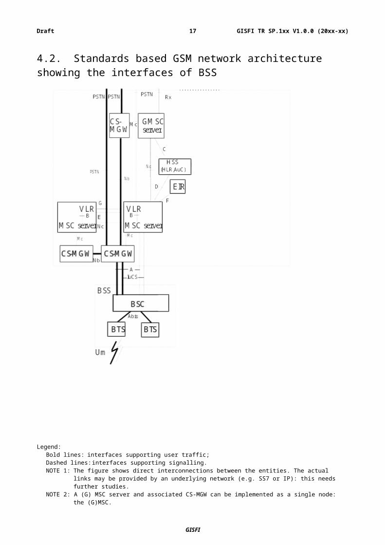
4.2. Standards based GSM network architecture showing the interfaces of BSS
Legend:Bold lines: interfaces supporting user traffic;Dashed lines: interfaces supporting signalling.NOTE 1: The figure shows direct interconnections between the entities. The actual links may be provided by an
underlying network (e.g. SS7 or IP): this needs further studies.NOTE 2: A (G) MSC server and associated CS-MGW can be implemented as a single node: the (G)MSC.
Figure 1: Basic Configuration of a PLMN supporting CS and interfaces Ref: 3GPP [5]
GISFI
GISFI TR SP.1xx V1.0.0 (20xx-xx)15Draft
4.2.1 The Access Network (AN) entities
4.2.1.1 The Base Station System (BSS)
The Base Station System (BSS) is the system of base station equipments (transceivers, controllers, etc.) which is viewed by the MSC through a single A interface as being the entity responsible for communicating with Mobile Stations (MSs) in a certain area. The functionality for the A interface is described in TS 48.002 [9].
The radio equipment of a BSS may support one or more cells. A BSS may consist of one or more base stations. Where an Abis-interface is implemented, the BSS consists of one Base Station Controller (BSC) and one or more Base Transceiver Station (BTS). The split of functions between BSS and CN for an A / Gb interface is described in the 48-series of GSM Technical Specifications. The mobile station shall operate using only the following modes:
a A / Gb mode, e.g. for pre-Release 4 terminals, or for Release 4 terminals when connected to a BSS with no Iu interface towards the Core Network.
b Iu mode, e.g. for Release 4 terminals when connected to a BSS with Iu interfaces towards the Core Network.
4.2.1.2 Base Station Controller (BSC)
A Base Station Controller (BSC) is a network component in the PLMN with the functions for control of one or more BTS.
4.2.1.3 Base Transceiver Station (BTS)
A Base Transceiver Station (BTS) is a network component which serves one cell.
4.2.1.4 The Mobile Station (MS)
The mobile station consists of the physical equipment used by a PLMN subscriber; it comprises the Mobile Equipment (ME) and the Subscriber Identity Module (SIM), called UMTS Subscriber Identity Module (USIM) for Release 99 and following. The ME comprises the Mobile Termination (MT) which, depending on the application and services, may support various combinations of Terminal Adapter (TA) and Terminal Equipment (TE) functional groups. These functional groups are described in TS 24.002 [10].
4.2.2 The Core Network (CN) Entities
4.2.2.1 The Home Location Register (HLR)
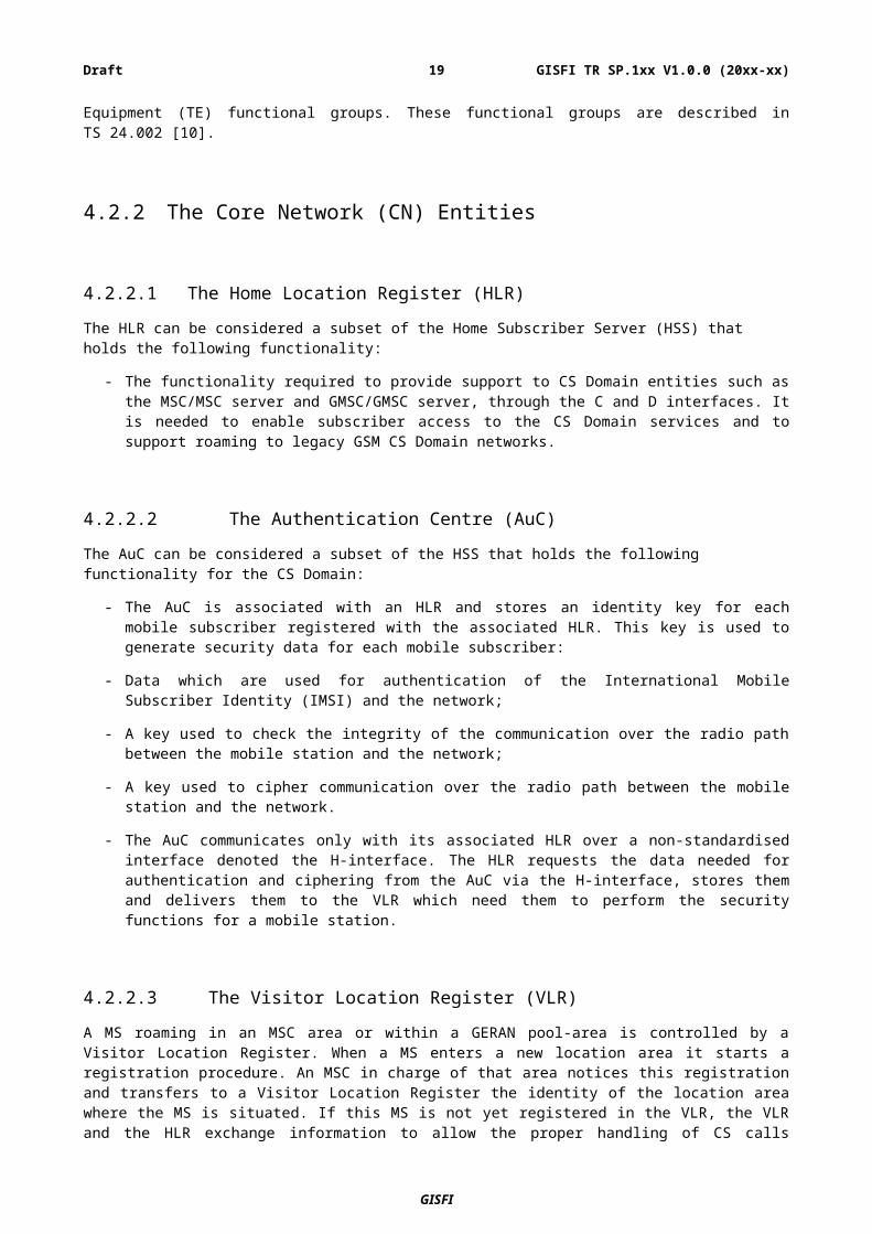
The HLR can be considered a subset of the Home Subscriber Server (HSS) that holds the following functionality:
- The functionality required to provide support to CS Domain entities such as the MSC/MSC server and GMSC/GMSC server, through the C and D interfaces. It is needed to enable subscriber access to the CS Domain services and to support roaming to legacy GSM CS Domain networks.
GISFI
GISFI TR SP.1xx V1.0.0 (20xx-xx)16Draft
4.2.2.2 The Authentication Centre (AuC)
The AuC can be considered a subset of the HSS that holds the following functionality for the CS Domain:
- The AuC is associated with an HLR and stores an identity key for each mobile subscriber registered with the associated HLR. This key is used to generate security data for each mobile subscriber:
- Data which are used for authentication of the International Mobile Subscriber Identity (IMSI) and the network;
- A key used to check the integrity of the communication over the radio path between the mobile station and the network;
- A key used to cipher communication over the radio path between the mobile station and the network.
- The AuC communicates only with its associated HLR over a non-standardised interface denoted the H-interface. The HLR requests the data needed for authentication and ciphering from the AuC via the H-interface, stores them and delivers them to the VLR which need them to perform the security functions for a mobile station.
4.2.2.3 The Visitor Location Register (VLR)
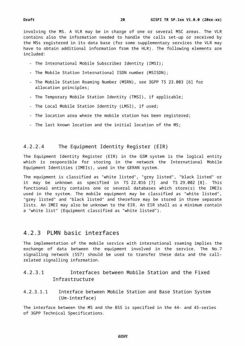
A MS roaming in an MSC area or within a GERAN pool-area is controlled by a Visitor Location Register. When a MS enters a new location area it starts a registration procedure. An MSC in charge of that area notices this registration and transfers to a Visitor Location Register the identity of the location area where the MS is situated. If this MS is not yet registered in the VLR, the VLR and the HLR exchange information to allow the proper handling of CS calls involving the MS. A VLR may be in charge of one or several MSC areas. The VLR contains also the information needed to handle the calls set-up or received by the MSs registered in its data base (for some supplementary services the VLR may have to obtain additional information from the HLR). The following elements are included:
- The International Mobile Subscriber Identity (IMSI);
- The Mobile Station International ISDN number (MSISDN);
- The Mobile Station Roaming Number (MSRN), see 3GPP TS 23.003 [6] for allocation principles;
- The Temporary Mobile Station Identity (TMSI), if applicable;
- The Local Mobile Station Identity (LMSI), if used;
- The location area where the mobile station has been registered;
- The last known location and the initial location of the MS;
4.2.2.4 The Equipment Identity Register (EIR)
The Equipment Identity Register (EIR) in the GSM system is the logical entity which is responsible for storing in the network the International Mobile Equipment Identities (IMEIs), used in the GERAN system.
The equipment is classified as "white listed", "grey listed", "black listed" or it may be unknown as specified in TS 22.016 [7] and TS 29.002 [8]. This functional entity contains one or several databases which store(s) the IMEIs used in the system. The mobile equipment may be classified as "white listed", "grey listed" and "black listed" and therefore may be stored in three separate lists. An IMEI may also be unknown to the EIR. An EIR shall as a minimum contain a "white list" (Equipment classified as "white listed").
4.2.3 PLMN basic interfacesThe implementation of the mobile service with international roaming implies the exchange of data between the equipment involved in the service. The No.7 signalling network (SS7) should be used to transfer these data and the call-related signalling information.
GISFI
GISFI TR SP.1xx V1.0.0 (20xx-xx)17Draft
4.2.3.1 Interfaces between Mobile Station and the Fixed Infrastructure
4.2.3.1.1 Interface between Mobile Station and Base Station System (Um-interface)
The interface between the MS and the BSS is specified in the 44- and 45-series of 3GPP Technical Specifications.
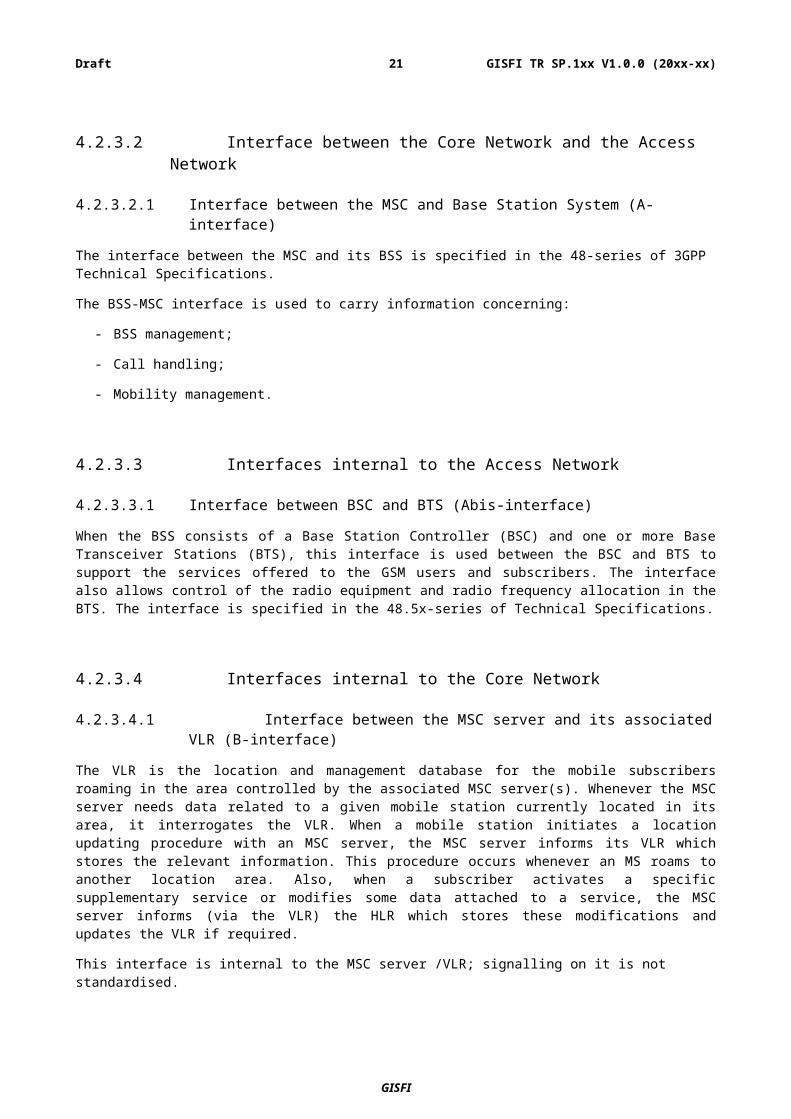
4.2.3.2 Interface between the Core Network and the Access Network
4.2.3.2.1 Interface between the MSC and Base Station System (A-interface)
The interface between the MSC and its BSS is specified in the 48-series of 3GPP Technical Specifications.
The BSS-MSC interface is used to carry information concerning:
- BSS management;
- Call handling;
- Mobility management.
4.2.3.3 Interfaces internal to the Access Network
4.2.3.3.1 Interface between BSC and BTS (Abis-interface)
When the BSS consists of a Base Station Controller (BSC) and one or more Base Transceiver Stations (BTS), this interface is used between the BSC and BTS to support the services offered to the GSM users and subscribers. The interface also allows control of the radio equipment and radio frequency allocation in the BTS. The interface is specified in the 48.5x-series of Technical Specifications.
4.2.3.4 Interfaces internal to the Core Network
4.2.3.4.1 Interface between the MSC server and its associated VLR (B-interface)
The VLR is the location and management database for the mobile subscribers roaming in the area controlled by the associated MSC server(s). Whenever the MSC server needs data related to a given mobile station currently located in its area, it interrogates the VLR. When a mobile station initiates a location updating procedure with an MSC server, the MSC server informs its VLR which stores the relevant information. This procedure occurs whenever an MS roams to another location area. Also, when a subscriber activates a specific supplementary service or modifies some data attached to a service, the MSC server informs (via the VLR) the HLR which stores these modifications and updates the VLR if required.
This interface is internal to the MSC server /VLR; signalling on it is not standardised.
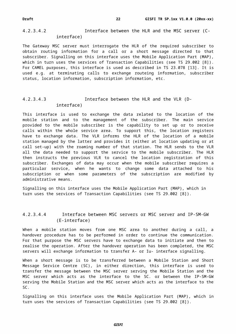
4.2.3.4.2 Interface between the HLR and the MSC server (C-interface)
The Gateway MSC server must interrogate the HLR of the required subscriber to obtain routing information for a call or a short message directed to that subscriber. Signalling on this interface uses the Mobile Application Part (MAP), which in turn uses the services of Transaction Capabilities (see TS 29.002 [8]). For CAMEL purposes, this interface is used as described in TS 23.078 [13]. It is used e.g. at terminating calls to exchange routeing information, subscriber status, location information, subscription information, etc.
GISFI
GISFI TR SP.1xx V1.0.0 (20xx-xx)18Draft
4.2.3.4.3 Interface between the HLR and the VLR (D-interface)
This interface is used to exchange the data related to the location of the mobile station and to the management of the subscriber. The main service provided to the mobile subscriber is the capability to set up or to receive calls within the whole service area. To support this, the location registers have to exchange data. The VLR informs the HLR of the location of a mobile station managed by the latter and provides it (either at location updating or at call set-up) with the roaming number of that station. The HLR sends to the VLR all the data needed to support the service to the mobile subscriber. The HLR then instructs the previous VLR to cancel the location registration of this subscriber. Exchanges of data may occur when the mobile subscriber requires a particular service, when he wants to change some data attached to his subscription or when some parameters of the subscription are modified by administrative means.
Signalling on this interface uses the Mobile Application Part (MAP), which in turn uses the services of Transaction Capabilities (see TS 29.002 [8]).
4.2.3.4.4 Interface between MSC servers or MSC server and IP-SM-GW (E-interface)
When a mobile station moves from one MSC area to another during a call, a handover procedure has to be performed in order to continue the communication. For that purpose the MSC servers have to exchange data to initiate and then to realise the operation. After the handover operation has been completed, the MSC servers will exchange information to transfer A- or Iu- interface signalling.
When a short message is to be transferred between a Mobile Station and Short Message Service Centre (SC), in either direction, this interface is used to transfer the message between the MSC server serving the Mobile Station and the MSC server which acts as the interface to the SC. or between the IP-SM-GW serving the Mobile Station and the MSC server which acts as the interface to the SC.
Signalling on this interface uses the Mobile Application Part (MAP), which in turn uses the services of Transaction Capabilities (see TS 29.002 [8]).
4.2.3.4.5 Interface between MSC server and EIR (F-interface)
This interface is used between MSC server and EIR to exchange data, in order that the EIR can verify the status of the IMEI retrieved from the Mobile Station.
Signalling on this interface uses the Mobile Application Part (MAP), which in turn uses the services of Transaction Capabilities (see TS 29.002 [8]).
4.2.3.4.6 Interface between VLRs (G-interface)
When a mobile subscriber moves from a VLR area to another Location Registration procedure will happen. This procedure may include the retrieval of the IMSI and authentication parameters from the old VLR.
Signalling on this interface uses the Mobile Application Part (MAP), which in turn uses the services of Transaction Capabilities (see TS 29.002 [8]).
4.2.3.4.7 Interface between HLR/HSS and AuC (H-Interface)
When an HLR/HSS receives a request for authentication and ciphering data for a Mobile Subscriber and it does not hold the requested data, the HLR/HSS requests the data from the AuC. The protocol used to transfer the data over this interface is not standardised
GISFI
GISFI TR SP.1xx V1.0.0 (20xx-xx)19Draft
4.3. Various practical configurations of BSS deployment The following configurations of BSS deployment are feasible:
– Collocated BTS Configuration: BTS is situated along with BSC or the MSC and no additional E1 link is required
– Remote Configuration: BTS is situated in a standalone position and additional E1 links are required to connect to BSC
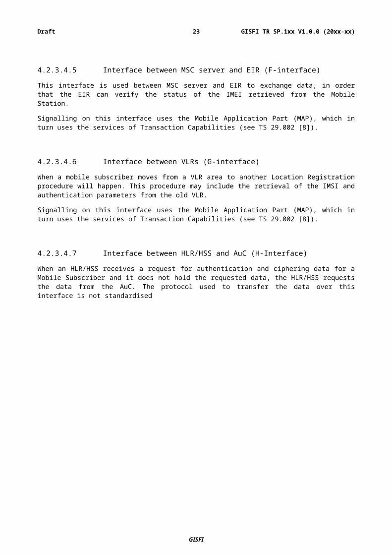
– Star Configuration
Figure 2: Star Configuration
Easy to implement but poor utilization of links, Each BTS require one E1 to connect to BSC. But if the link goes down only individual B TS will be affected.
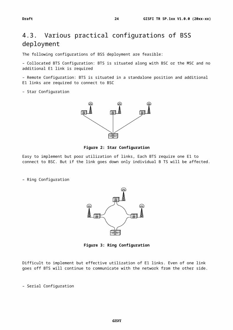
– Ring Configuration
Figure 3: Ring Configuration
Difficult to implement but effective utilization of E1 links. Even of one link goes off BTS will continue to communicate with the network from the other side.
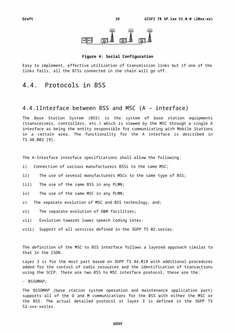
– Serial Configuration
Figure 4: Serial Configuration
Easy to implement, effective utilization of transmission links but if one of the links fails, all the BTSs connected in the chain will go off.
GISFI
GISFI TR SP.1xx V1.0.0 (20xx-xx)20Draft
4.4. Protocols in BSS
4.4.1 Interface between BSS and MSC (A – interface) The Base Station System (BSS) is the system of base station equipments (transceivers, controllers, etc.) which is viewed by the MSC through a single A interface as being the entity responsible for communicating with Mobile Stations in a certain area. The functionality for the A interface is described in TS 48.002 [9].
The A-Interface interface specifications shall allow the following:
i) Connection of various manufacturers BSSs to the same MSC;
ii) The use of several manufacturers MSCs to the same type of BSS;
iii) The use of the same BSS in any PLMN;
iv) The use of the same MSC in any PLMN;
v) The separate evolution of MSC and BSS technology, and;
vi) The separate evolution of O&M facilities;
vii) Evolution towards lower speech coding rates;
viii) Support of all services defined in the 3GPP TS 02.series.
The definition of the MSC to BSS interface follows a layered approach similar to that in the ISDN.
Layer 3 is for the most part based on 3GPP TS 44.018 with additional procedures added for the control of radio resources and the identification of transactions using the SCCP. There are two BSS to MSC interface protocol, these are the:
- BSSOMAP;
The BSSOMAP (base station system operation and maintenance application part) supports all of the O and M communications for the BSS with either the MSC or the BSS. The actual detailed protocol at layer 3 is defined in the 3GPP TS 52.xxx-series.
- BSSAP.
The BSSAP is further subdivided into two sub-protocols, the BSSMAP and the Direct Transfer Application Part (DTAP).
The base station system management application part (BSSMAP) is that part of the protocol responsible for all aspects of the radio resource handling at the BSS. The text is structured as a set of procedures which are defined separately and can be employed as felt appropriate by the operator/manufacturer to meet the requirements of the application in which it is being used. The procedures themselves can be driven in different modes depending upon the input parameters received from the MSC or sent from the OMC.
The DTAP text is split between 3GPP TS 48.006 and 3GPP TS 48.008 but the text in 3GPP TS 48.008 defines which layer 3 air interface messages are passed transparently through the BSS and which are analysed at the BSS.
Layer 2 is based on the Signalling System No.7 (SS7) Message Transfer Part (MTP), or in the case of IP-based signalling transport - M3UA and SCTP. This is documented in 3GPP TS 48.006. For IP-based signalling transport, the involved nodes may take the role of a client or a server with respect to establishing the end-to-end communication. The particular role of the nodes is either determined by configuration or is depending on which peer acting first in establishing the communication, by that is acting as the client. The identification of the transaction involved implies some form of logical connection. This is achieved by using the Signalling Connection Control Part (SCCP) of SS7.
GISFI
GISFI TR SP.1xx V1.0.0 (20xx-xx)21Draft
In case of SS7 MTP, layer 1 is either digital (at 2048 kbit/s, based on ITU-T Recommendation G.703 clause 6) or analogue with the data being passed by the use of modems (this latter case is a national option). The specifications are provided in 3GPP TS 48.004. The speech coding is either according to ITU-T G.711 or according to Codecs listed in 3GPP TS 26.103.
4.4.2 Interface between BSC and BTS (Abis-interface)When the BSS consists of a Base Station Controller (BSC) and one or more Base Transceiver Stations (BTS), this interface is used between the BSC and BTS to support the services offered to the GSM users and subscribers. The interface also allows control of the radio equipment and radio frequency allocation in the BTS. The interface is specified in the 48.5x-series of Technical Specifications.
The Abis interface specifications should allow the following:
(i) Connection of various manufacturers BTS/TRX to the same BSC, according to the location of the transcoder.
(ii) The use of several manufacturers BSC to the same type of BTS/TRX, according to the location of the transcoder.
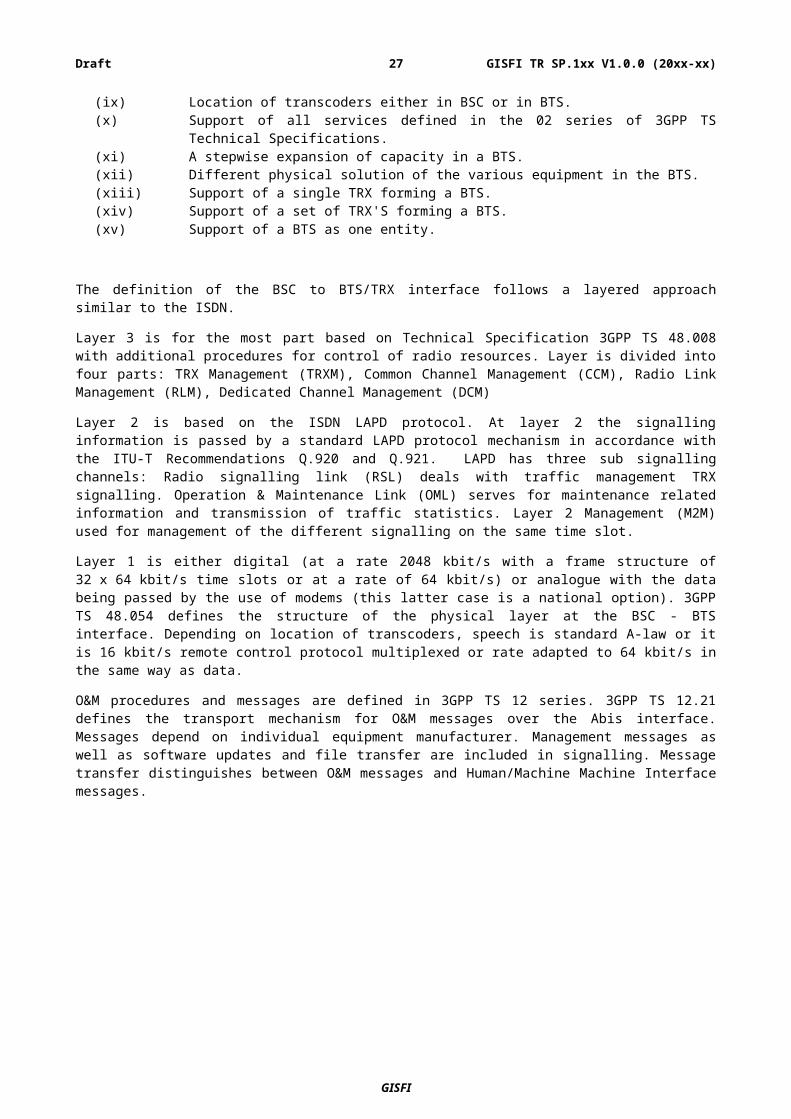
(iii) The use of the same BTS/TRX in any PLMN, according to the location of the transcoder.(iv) The use of the same BSC in any PLMN.(v) Separate evolution of BSC and BTS/TRX technology.(vi) Separate evolution of O & M facilities.(vii) Sub-multiplexing of speech channels on a 64 kbit circuit.(viii) Evolution towards lower speech coding rates.(ix) Location of transcoders either in BSC or in BTS.(x) Support of all services defined in the 02 series of 3GPP TS Technical Specifications.(xi) A stepwise expansion of capacity in a BTS. (xii) Different physical solution of the various equipment in the BTS.(xiii) Support of a single TRX forming a BTS. (xiv) Support of a set of TRX'S forming a BTS. (xv) Support of a BTS as one entity.
The definition of the BSC to BTS/TRX interface follows a layered approach similar to the ISDN.
Layer 3 is for the most part based on Technical Specification 3GPP TS 48.008 with additional procedures for control of radio resources. Layer is divided into four parts: TRX Management (TRXM), Common Channel Management (CCM), Radio Link Management (RLM), Dedicated Channel Management (DCM)
Layer 2 is based on the ISDN LAPD protocol. At layer 2 the signalling information is passed by a standard LAPD protocol mechanism in accordance with the ITU-T Recommendations Q.920 and Q.921. LAPD has three sub signalling channels: Radio signalling link (RSL) deals with traffic management TRX signalling. Operation & Maintenance Link (OML) serves for maintenance related information and transmission of traffic statistics. Layer 2 Management (M2M) used for management of the different signalling on the same time slot.
Layer 1 is either digital (at a rate 2048 kbit/s with a frame structure of 32 x 64 kbit/s time slots or at a rate of 64 kbit/s) or analogue with the data being passed by the use of modems (this latter case is a national option). 3GPP TS 48.054 defines the structure of the physical layer at the BSC - BTS interface. Depending on location of transcoders, speech is standard A-law or it is 16 kbit/s remote control protocol multiplexed or rate adapted to 64 kbit/s in the same way as data.
O&M procedures and messages are defined in 3GPP TS 12 series. 3GPP TS 12.21 defines the transport mechanism for O&M messages over the Abis interface. Messages depend on individual equipment manufacturer. Management messages as well as software updates and file transfer are included in signalling. Message transfer distinguishes between O&M messages and Human/Machine Machine Interface messages.
GISFI
GISFI TR SP.1xx V1.0.0 (20xx-xx)22Draft
5 Security Threats and RequirementsThis section will discuss security threats and requirements of BSS as per applicable 3GPP standards [10, 11, and 12]:
5.1 General security requirements
The use of radio communications for transmission to the mobile subscribers makes PLMNs particularly sensitive to [11]:
- Misuse of their resources by unauthorized persons using manipulated Mobile Stations, who try to impersonate authorized subscribers; and
- Eavesdropping of the various information which are exchanged on the radio path.
This leads to the requirement to implement security features in a GSM PLMN in order to protect:
i) The access to the mobile services;
ii) Any relevant item from being disclosed at the radio path, mainly in order to ensure the privacy of user related information.
The following security features are considered for GSM networks:
- Subscriber identity (IMSI) confidentiality;
- Subscriber identity (IMSI) authentication;
- User data confidentiality on physical connections;
- Connectionless user data confidentiality;
- Signalling information element confidentiality.
The implementation of these five security features is mandatory on both the fixed infrastructure side and the MS side. This means that all GSM PLMNs and all MSs shall be able to support every security feature. Use of these five security features is at the discretion of the operator for its own subscribers while on the HPLMN. For roaming subscribers, use of these five security features is mandatory unless otherwise agreed by all the affected PLMN operators.
5.2 Requirements from certification bodies etc. if available, e.g. GCF
-Details Not Available-
GISFI
GISFI TR SP.1xx V1.0.0 (20xx-xx)23Draft
5.3 Security requirements from specifications [11, 12]
5.3.1 Subscriber identity confidentiality (IMSI related)The subscriber identity confidentiality feature is the property that the IMSI is not made available or disclosed to unauthorized individuals, entities or processes.
5.3.1.1 Functional requirements
Confidentiality of the subscriber identity (IMSI) when it is transferred in signalling messages is a mandatory requirement. Along with this, specific measures to preclude the possibility to derive it indirectly from listening to specific information, such as addresses, at the radio path are important.
The means used to identify a mobile subscriber on the radio path consists of a local number called Temporary Mobile Subscriber Identity (TMSI). When used, the subscriber identity confidentiality feature shall apply for all signalling sequences on the radio path. However, in the case of location register failure, or in case the MS has no TMSI available, open identification is allowed on the radio path.
5.3.2 Subscriber identity authenticationThe purpose of this authentication security feature is to protect the network against unauthorized use. It enables also the protection of the GSM PLMN subscribers by denying the possibility for intruders to impersonate authorized users.
5.3.2.1 Functional requirements
The authentication of the GSM PLMN subscriber identity may be triggered by the network when the subscriber applies for:
a. A change of subscriber related information element in the VLR or HLR (including some or all of: location updating involving change of VLR, registration or erasure of a supplementary service); or
b. An access to a service (including some or all of: set up of mobile originating or terminated calls, activation or deactivation of a supplementary service); or
c. First network access after restart of MSC/VLR; or
d. In the event of cipher key sequence number mismatch.
Two network functions are necessary: the authentication procedure itself, and the key management inside the fixed subsystem.
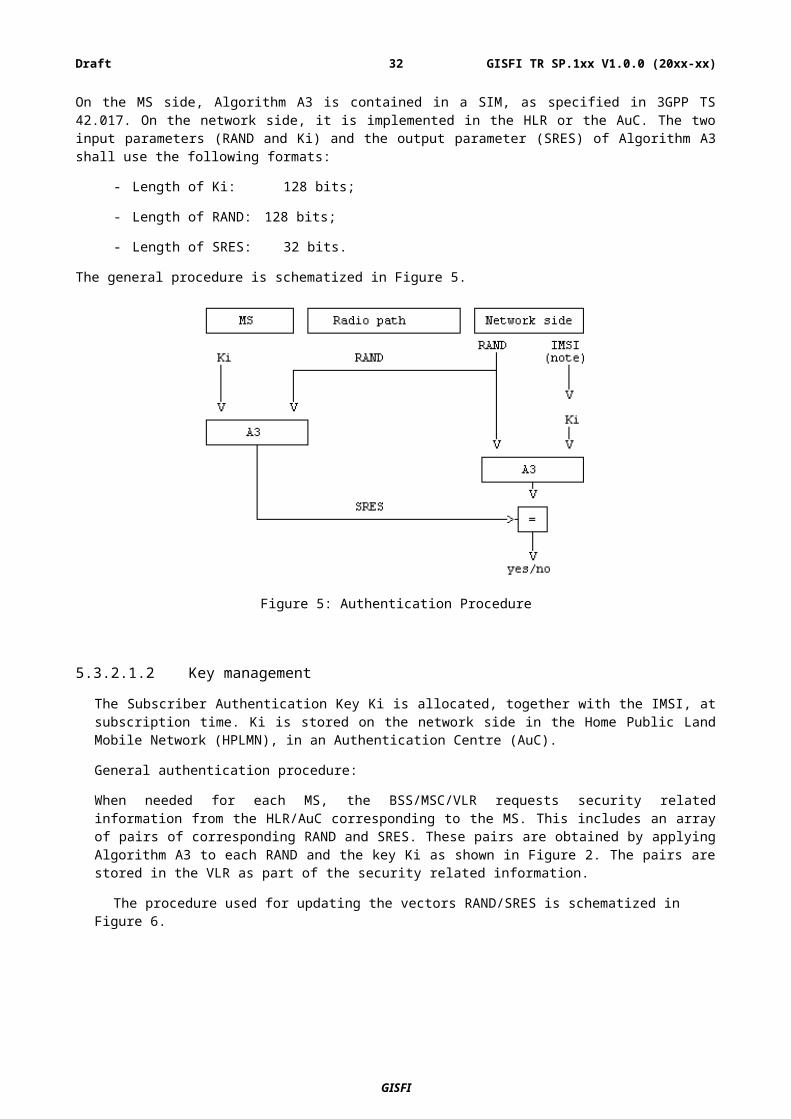
5.3.2.1.1 Authentication procedure
The authentication procedure consists of the following exchange between the fixed subsystem and the MS.
- The fixed subsystem transmits a non-predictable number RAND to the MS.
- The MS computes the signature of RAND, say SRES, using algorithm A3 and some secret information: the Individual Subscriber Authentication Key, denoted by Ki.
- The MS transmits the signature SRES to the fixed subsystem.
- The fixed subsystem tests SRES for validity.
GISFI
GISFI TR SP.1xx V1.0.0 (20xx-xx)24Draft
On the MS side, Algorithm A3 is contained in a SIM, as specified in 3GPP TS 42.017. On the network side, it is implemented in the HLR or the AuC. The two input parameters (RAND and Ki) and the output parameter (SRES) of Algorithm A3 shall use the following formats:
- Length of Ki: 128 bits;
- Length of RAND: 128 bits;
- Length of SRES: 32 bits.
The general procedure is schematized in Figure 5.
Figure 5: Authentication Procedure
5.3.2.1.2 Key management
The Subscriber Authentication Key Ki is allocated, together with the IMSI, at subscription time. Ki is stored on the network side in the Home Public Land Mobile Network (HPLMN), in an Authentication Centre (AuC).
General authentication procedure:
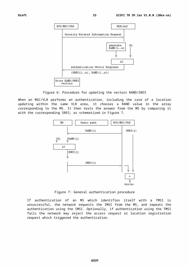
When needed for each MS, the BSS/MSC/VLR requests security related information from the HLR/AuC corresponding to the MS. This includes an array of pairs of corresponding RAND and SRES. These pairs are obtained by applying Algorithm A3 to each RAND and the key Ki as shown in Figure 2. The pairs are stored in the VLR as part of the security related information.
The procedure used for updating the vectors RAND/SRES is schematized in Figure 6.
GISFI
GISFI TR SP.1xx V1.0.0 (20xx-xx)25Draft
Figure 6: Procedure for updating the vectors RAND/SRES
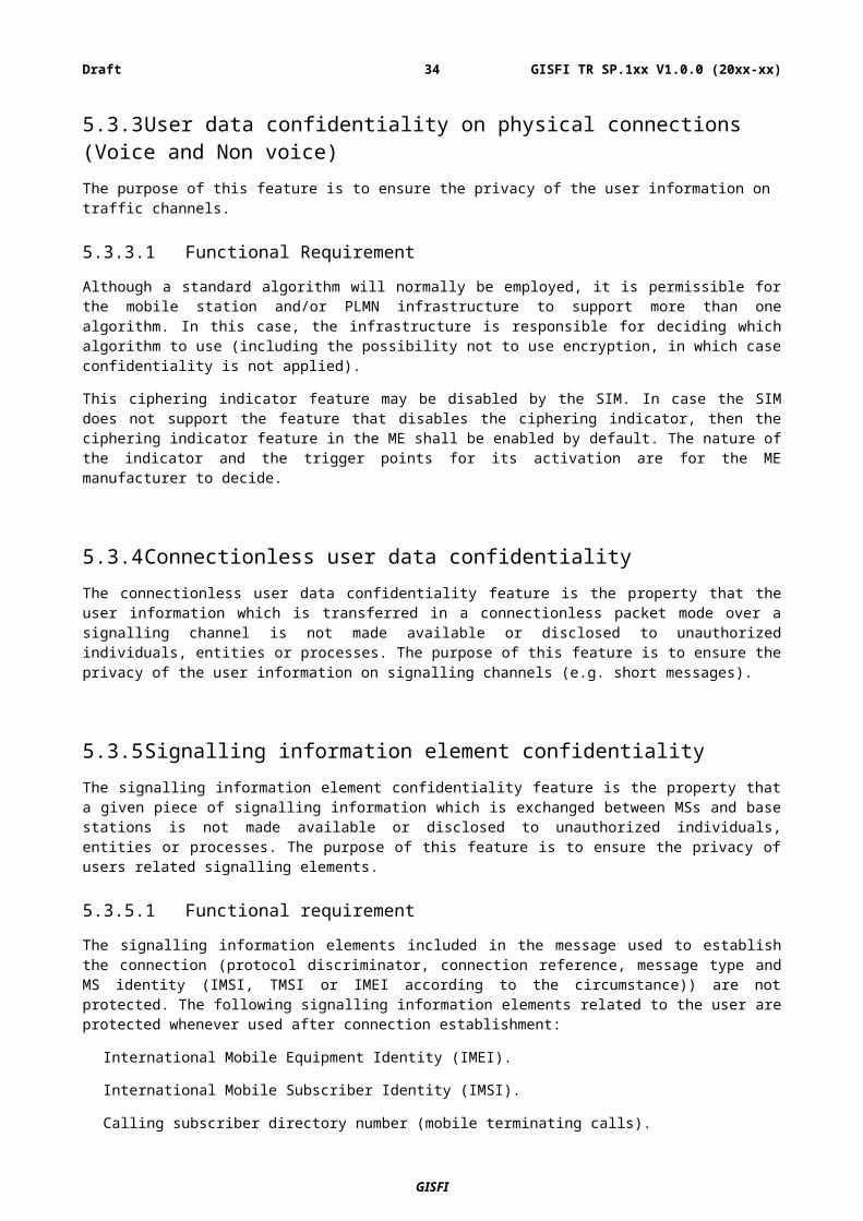
When an MSC/VLR performs an authentication, including the case of a location updating within the same VLR area, it chooses a RAND value in the array corresponding to the MS. It then tests the answer from the MS by comparing it with the corresponding SRES, as schematized in Figure 7.
Figure 7: General authentication procedure
If authentication of an MS which identifies itself with a TMSI is unsuccessful, the network requests the IMSI from the MS, and repeats the authentication using the IMSI. Optionally, if authentication using the TMSI fails the network may reject the access request or location registration request which triggered the authentication.
GISFI
GISFI TR SP.1xx V1.0.0 (20xx-xx)26Draft
5.3.3 User data confidentiality on physical connections (Voice and Non voice)The purpose of this feature is to ensure the privacy of the user information on traffic channels.
5.3.3.1 Functional Requirement
Although a standard algorithm will normally be employed, it is permissible for the mobile station and/or PLMN infrastructure to support more than one algorithm. In this case, the infrastructure is responsible for deciding which algorithm to use (including the possibility not to use encryption, in which case confidentiality is not applied).
This ciphering indicator feature may be disabled by the SIM. In case the SIM does not support the feature that disables the ciphering indicator, then the ciphering indicator feature in the ME shall be enabled by default. The nature of the indicator and the trigger points for its activation are for the ME manufacturer to decide.
5.3.4 Connectionless user data confidentialityThe connectionless user data confidentiality feature is the property that the user information which is transferred in a connectionless packet mode over a signalling channel is not made available or disclosed to unauthorized individuals, entities or processes. The purpose of this feature is to ensure the privacy of the user information on signalling channels (e.g. short messages).
5.3.5 Signalling information element confidentialityThe signalling information element confidentiality feature is the property that a given piece of signalling information which is exchanged between MSs and base stations is not made available or disclosed to unauthorized individuals, entities or processes. The purpose of this feature is to ensure the privacy of users related signalling elements.
5.3.5.1 Functional requirement
The signalling information elements included in the message used to establish the connection (protocol discriminator, connection reference, message type and MS identity (IMSI, TMSI or IMEI according to the circumstance)) are not protected. The following signalling information elements related to the user are protected whenever used after connection establishment:
International Mobile Equipment Identity (IMEI).
International Mobile Subscriber Identity (IMSI).
Calling subscriber directory number (mobile terminating calls).
Called subscriber directory number (mobile originated calls).
The IMSI is stored securely within the SIM. The IMEI shall not be changed after the ME’s final production process. It shall resist tampering, i.e. manipulation and change, by any means (e.g. physical, electrical and software).
GISFI
GISFI TR SP.1xx V1.0.0 (20xx-xx)27Draft
Four points have to be specified:
5.3.5.1.1 The ciphering method
The layer 1 data flow (transmitted on DCCH or TCH) is ciphered by a bit per bit or stream cipher, i.e. the data flow on the radio path is obtained by the bit per bit binary addition of the user data flow and a ciphering bit stream, generated by algorithm A5 using a key. The key is denoted below by Kc if it is the 64-bit key and is called "Ciphering Key".
5.3.5.1.2 The key setting
Mutual key setting is the procedure that allows the mobile station and the network to agree on the key Kc to use in the ciphering and deciphering algorithms A5. A key setting is triggered by the authentication procedure. Key setting must occur on a DCCH not yet encrypted and as soon as the identity of the mobile subscriber (i.e. TMSI or IMSI) is known by the network. The transmission of Kc to the MS is indirect and uses the authentication RAND value; Kc is derived from RAND by using algorithm A8 and the Subscriber Authentication key Ki.
Figure 8: Key setting
Support for algorithm A8 is at each PLMN operator discretion. On the MS side, Algorithm A8 is contained in the SIM, as specified in 3GPP TS 42.017. On the network side, Algorithm A8 is co-located with Algorithm A3. The two input parameters (RAND and Ki) and the output parameter (Kc) of Algorithm A8 shall follow the following formats:
- Length of Ki: 128 bits;
- Length of RAND: 128 bits;
- Length of Kc: 64 bits.
Since the maximum length of the actual ciphering key is fixed by GSM/MoU, Algorithm A8 shall produce this actual ciphering key and extend it (if necessary) into a 64 bit word where the non-significant bits are forced to zero. It is assumed that any non-significant bits are the least significant bits and that; the actual ciphering key is contained in the most significant bits. For signalling and testing purposes the ciphering key Kc has to be considered as 64 unstructured bits.
5.3.5.1.3 The starting of the enciphering and deciphering processes
The MS and the BSS must co-ordinate the instants at which the enciphering and deciphering processes start on DCCH and TCH. On DCCH, this procedure takes place under the control of the network sometime after the completion of the authentication procedure (if any), or after the key Kc has been made available at the BSS. No information elements for which protection is needed must be sent before the ciphering and deciphering processes are operating.
GISFI
GISFI TR SP.1xx V1.0.0 (20xx-xx)28Draft

The transition from clear text mode to ciphered mode proceeds as follows: deciphering starts in the BSS, which sends in clear text to the MS a specific message, here called "Start cipher". Both the enciphering and deciphering start on the MS side after the message "Start cipher" has been correctly received by the MS. Finally, enciphering on the BSS side starts as soon as a frame or a message from the MS has been correctly deciphered at the BSS.
The starting of enciphering and deciphering processes is schematized in Figure 9.
Figure 9: Starting of the enciphering and deciphering processes
5.3.5.1.4 The synchronization
The enciphering stream at one end and the deciphering stream at the other end must be synchronized, for the enciphering bit stream and the deciphering bit streams to coincide.
Synchronization is guaranteed by driving Algorithm A5 by an explicit time variable, COUNT, derived from the TDMA frame number. Therefore each Number of Payload Bits per Burst NPBB-bit block produced by A5 depends only on the TDMA frame numbering and the ciphering key Kc.
COUNT is expressed in 22 bits as the concatenation of the binary representation of T1, T3 and T2. It is an input parameter of Algorithm A5. The coding of COUNT is shown in Figure 10.
Figure 10: The coding of COUNT
Bit 22 is the most significant bit (msb) and bit 1 the least significant bit (lsb) of COUNT. T1, T3 and T2 are represented in binary. The synchronization channel carries information for frame synchronization of the mobile station and identification of a base transceiver station. Specifically the synchronization channel (SCH) shall contain two encoded parameters:
a) Base transceiver station identity code (BSIC): 6 bits (before channel coding) consists of 3 bits of PLMN colour code with range 0 to 7 and 3 bits of BS colour code with range 0 to 7 as defined in 3GPP TS 23.003.
b) Reduced TDMA frame number (RFN): 19 bits (before channel coding) =
T1 (11 bits) range 0 to 2047 = FN div (26 x 51)
T2 (5 bits) range 0 to 25 = FN mod 26
T3 ' (3 bits) range 0 to 4 = (T3 - 1) div 10
where
GISFI
GISFI TR SP.1xx V1.0.0 (20xx-xx)29Draft
T3 (6 bits) range 0 to 50 = FN mod 51
and
FN = TDMA frame number.
3GPP TS 44.006 and 3GPP TS 44.018 specify the precise bit ordering, 3GPP TS 45.003 the channel coding of the above parameters and 3GPP TS 45.010 defines how the TDMA frame number can be calculated from T1, T2, and T3'.
5.3.6 Algorithm A5: Ciphering/deciphering algorithm
5.3.6.1 Negotiation of A5 algorithm
When an MS wishes to establish a connection with the network, the MS shall indicate to the network which of the seven versions of the A5 algorithm it supports. The network shall not provide service to an MS which indicates that it does not support the ciphering algorithm A5/1. The network shall compare its ciphering capabilities and preferences, and any special requirements of the subscription of the MS, with those indicated by the MS and act according to the following rules:
1) If the MS and the network have no versions of the A5 algorithm in common and the network is not prepared to use an unciphered connection, then the connection shall be released.
2) If the MS and the network have at least one version of the A5 algorithm in common, then the network shall select one of the mutually acceptable versions of the A5 algorithm for use on that connection.
3) If the MS and the network have no versions of the A5 algorithm in common and the network is willing to use an unciphered connection, then an unciphered connection shall be used.
5.3.6.2 Support of A5 Algorithms in MS
It is mandatory for A5/1, A5/3, A5/4 and non encrypted mode to be implemented in mobile stations. It is prohibited to implement A5/2 in mobile stations. Only A5 algorithms that are included in 3GPP specifications shall be implemented in mobile stations.
5.3.6.3 Support of A5 Algorithms in BSS
It is mandatory for A5/3 and A5/4 to be implemented in the BSS.
GISFI
GISFI TR SP.1xx V1.0.0 (20xx-xx)30Draft
5.3.6.4 Overview of A5 Algorithm
Algorithm A5 must be common to all GSM PLMNs and all mobile stations (in particular, to allow roaming). The external specifications of Algorithm A5 are defined by 3GPP. The internal specifications of Algorithm A5 are managed under the responsibility of GSMA.
Figure 10: Enciphering and deciphering processes
The useful data (plain text) are organized into blocks of NPBB (Number of Payload Bits per Burst) bits. In the GMSK case NPBB is equal to 114. Then, each block is incorporated into a normal burst (see 3GPP TS 45.002) and transmitted during a time slot. According to 3GPP TS 45.003, in the GMSK case,, the useful information bits into a block are numbered e0 to e56 and e59 to e115 (the flag bits e57 and e58 are ignored). Successive slots for a given physical channel are separated at least by frame duration; approximately 4.615 ms (see 3GPP TS 45.001). For ciphering, Algorithm A5 produces, each 4.615 ms, a sequence of NPBB encipher/decipher bits (here called BLOCK) which is combined by a bit-wise modulo 2 addition with the NPBB-bit plain text block.
The two input parameters (COUNT and Kc) and the output parameters (BLOCK1 and BLOCK2) of Algorithm A5 shall use the following formats:
- length of Kc: 64 bits;
- length of COUNT: 22 bits;
- length of BLOCK1: NPBB bits;
- length of BLOCK2: NPBB bits.
5.3.6 Algorithm A3: Key GenerationAlgorithm A3 is considered as a matter for GSM PLMN operators. Therefore, only external specifications are given by 3GPP.
5.3.6.1 Purpose
As defined in 3GPP TS 43.020, the purpose of Algorithm A3 is to allow authentication of a mobile subscriber's identity.
To this end, Algorithm A3 must compute an expected response SRES from a random challenge RAND sent by the network. For this computation, Algorithm A3 makes use of the secret authentication key Ki.
GISFI
GISFI TR SP.1xx V1.0.0 (20xx-xx)31Draft
5.3.6.2 Implementation and operational requirements
On the MS side, Algorithm A3 is contained in a Subscriber Identity Module, as specified in 3GPP TS 42.017.
On the network side, it is implemented in the HLR or the AuC. The two input parameters (RAND and Ki) and the output parameter (SRES) of Algorithm A3 shall use the following formats:
- length of Ki: 128 bits;
- length of RAND: 128 bits;
- length of SRES: 32 bits.
The run-time of Algorithm A3 shall be less than 500 ms.
5.3.7 Algorithm A8: Key GenerationAlgorithm A8 is considered as a matter for GSM PLMN operators as is Algorithm A3.
5.3.7.1 Purpose
As defined in 3GPP TS 43.020, Algorithm A8 must compute the ciphering key Kc from the random challenge RAND sent during the authentication procedure, using the authentication key Ki.
5.3.7.2 Implementation and operational requirements
On the MS side, Algorithm A8 is contained in the SIM, as specified in 3GPP TS 42.017.
On the network side, Algorithm A8 is co-located with Algorithm A3.
The two input parameters (RAND and Ki) and the output parameter (Kc) of Algorithm A8 shall follow the following formats:
- length of Ki: 128 bits;
- length of RAND: 128 bits;
- length of Kc: 64 bits.
Since the maximum length of the actual ciphering key is fixed by GSM/MoU, Algorithm A8 shall produce this actual ciphering key and extend it (if necessary) into a 64 bit word where the non-significant bits are forced to zero. It is assumed that any non-significant bits are the least significant bits and that, the actual ciphering key is contained in the most significant bits. For signalling and testing purposes the ciphering key Kc has to considered to be 64 unstructured bits.
GISFI
GISFI TR SP.1xx V1.0.0 (20xx-xx)32Draft
5.4 Threats and requirements from threatsThe purpose of this section is to list possible security threats to the GSM BSS, detailing what the threats achieve, how they are carried out and where in the system they could occur. The following are the general categories of threats encountered by the GSM system. These are derived based on the 3GPP analysis of security threats and requirements for the 3G network [15].
i. Unauthorised access to sensitive data -Violation of confidentiality
- Eavesdropping: An intruder intercepts calls or messages without detection.
- Masquerading: An intruder hoaxes an authorised user into believing that they are the legitimate system to obtain confidential information from the user; or an intruder hoaxes a legitimate system into believing that they are an authorised user to obtain system service or confidential information.
- Traffic analysis: An intruder observes the time, rate, length, source, and destination of messages to determine a user’s location or to learn whether an important business transaction is taking place.
ii. Unauthorised manipulation of sensitive data - Violation of integrity
- Manipulation of messages: Messages may be deliberately modified, inserted, replayed, or deleted by an intruder
iii. Disturbing or misusing network services - Leading to denial of service or reduced availability
- Intervention: An intruder may prevent an authorised user from using a service by jamming the user’s traffic, signalling, or control data.
- Resource exhaustion: An intruder may prevent an authorised user from using a service by overloading the service.
- Misuse of privileges: A user or a serving network may exploit their privileges to obtain unauthorised services or information.
- Abuse of services: An intruder may abuse some special service or facility to gain an advantage or to cause disruption to the network.
iv. Repudiation: A user or a network denies actions that have taken place.
v. Unauthorised access to services
- Intruders can access services by masquerading as users or network entities.
- Users or network entities can get unauthorised access to services by misusing their access rights.
GISFI
GISFI TR SP.1xx V1.0.0 (20xx-xx)33Draft
The threats associated with attacks on the radio interface are described in the following sub-sections:
5.4.1 Unauthorised access to dataT1a Eavesdropping user traffic: Intruders may eavesdrop user traffic on the radio interface. (Major threat in
GSM)
T1b Eavesdropping signalling or control data: Intruders may eavesdrop signalling data or control data on the radio interface. This may be used to access security management data or other information which may be useful in conducting active attacks on the system.
T1c Masquerading as a communications participant: Intruders may masquerade as a network element to intercept user traffic, signalling data or control data on the radio interface. (Major threat in GSM)
T1d Passive traffic analysis: Intruders may observe the time, rate, length, sources or destinations of messages on the radio interface to obtain access to information. (Major threat in GSM)
T1e Active traffic analysis: Intruders may actively initiate communications sessions and then obtain access to information through observation of the time, rate, length, sources or destinations of associated messages on the radio interface.
Apart from the above described threats, the following attacks are possible on the GSM system on radio interface.
T1f Active identity catching: An intruder may spoof a serving network and send a request for the permanent user identity to a targeted user to capture his permanent identity in clear text.
T1g Suppression of encryption between target and intruder: An intruder may succeed in disabling encryption on the radio interface by several means.
Description: There are multiple possibilities for this attack:
a. The intruder can either use a man-in-the-middle attack by establishing two connections, one to the user and one to a valid serving network (relaying data with or without modifications between a user and a valid serving network) or
b. Masquerade as a serving network without establishing a link to a real network. In any case, the intruder may be able to suppress encryption between the user and himself by sending the appropriate signalling messages.
c. Alternatively, the intruder may just manipulate the signalling messages by which the user and serving network agree on their ciphering capabilities to create an incompatibility that will prevent ciphering from being established.
The threats following these actions are described below:
T1h Eavesdropping of a genuine call: Once encryption is disabled, the intruder can capture signalling and user traffic.
T1i Answering a mobile originated call: When the target attempts to make a call, the intruder relays the messages between the target and the true network until after authentication is completed. The intruder cuts the connection with the true network suppresses encryption and proceeds to set up the call as a new call (to any suitable network) and under the intruder’s own full control.
Authentication data can get compromised, either during its transport between the home environment and the serving network, or by unauthorised access to databases.
T1k Forcing use of a compromised cipher key: The intruder obtains a sample of authentication data and uses it to convince the user that he is connected to a proper serving network, and forces the use of a compromised cipher key. The intruder may force the repeated use of the same authentication data to ensure the same encryption key will be used for many calls. Leads to continuous eavesdropping.
T1l Impersonating the user: The intruder obtains a sample of authentication data and uses it to impersonate a user towards the serving network. Masquerading as a base station towards the serving network (or eavesdropping on such a connection) could be used to obtain valid authentication data for this attack.
GISFI
GISFI TR SP.1xx V1.0.0 (20xx-xx)34Draft
T1m Reusing authentication data: The intruder forces the repeated use of the same authentication data. Weaknesses in the efficiency of the encryption protection may be exploited either for cipher cryptanalysis or protocol attacks.
5.4.2 Threats to integrityT2a Manipulation of user traffic: Intruders may modify, insert, replay or delete user traffic on the radio
interface. This includes both accidental and deliberate manipulation.
T2b Manipulation of signalling or control data: Intruders may modify, insert, replay or delete signalling data or control data on the radio interface. This includes both accidental and deliberate manipulation.
5.4.3 Denial of service attacksT3a Physical intervention: Intruders may prevent user traffic, signalling data and control data from being
transmitted on the radio interface by physical means. An example of physical intervention is jamming.
T3b Protocol intervention: Intruders may prevent user traffic, signalling data or control data from being transmitted on the radio interface by inducing specific protocol failures. These protocol failures may themselves be induced by physical means.
T3c Denial of service by masquerading as a communications participant: Intruders may deny service to a legitimate user by preventing user traffic, signalling data or control data from being transmitted on the radio interface by masquerading as a network element.
5.4.4 Unauthorised access to servicesT4a Masquerading as another user: An intruder may masquerade as another user towards the network. The
intruder first masquerades as a base station towards the user, then hijacks his connection after authentication has been performed.
T4b Hijacking services for outgoing calls: While the target camps on the false base station, the intruder pages the target for an incoming call. The user then initiates the call set-up procedure, which the intruder allows to occur between the serving network and the target, modifying the signalling elements such that to the serving network it appears as if the target wants to set-up a mobile originated call. After authentication the intruder releases the target, and subsequently uses the connection to make fraudulent calls on the target’s subscription. This could be possible if the network does not enable encryption, or if the intruder can disable encryption (as in T1g) or if the intruder has access to the cipher key (as in T1k).
T4c Hijacking incoming calls: While the target camps on the false base station, an associate of the intruder makes a call to the target’s number. The intruder allows call set-up between target and serving network. After authentication the intruder releases the target, and subsequently uses the connection to answer the call made by his associate. The target will have to pay for the roaming leg. This could be possible if the network does not enable encryption, or if the intruder can disable encryption (as in T1g) or if the intruder has access to the cipher key (as in T1k).
GISFI
GISFI TR SP.1xx V1.0.0 (20xx-xx)35Draft
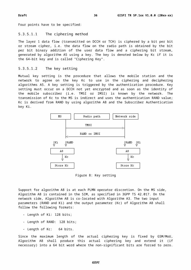
5.4.5 Protocol layers and threatsi. Unilateral authentication and vulnerability to the man-in-the-middle attack:
Unilateral authentication means that only the GSM network authenticates the mobile station (MS). The MS does not authenticate network so the attacker can use a false Base Station Transceiver (BTS) with the same mobile network code as the subscriber's legitimate network to impersonate, both the network and a user, and perform a man-in-the-middle attack. [T4b, T4c]
The attacker can then perform several scenarios to modify or fabricate the exchanged data. Impersonation of a user is the capability whereby the intruder sends signalling and/or user data to the network, in an attempt to make the network believe they originate from the target user. [T1l, T4a]
Impersonation of the network (false BTS) is the capability whereby the intruder sends signalling and/or user data to the target user, in an attempt to make the target user believe they originate from a genuine network. [T1c, T1g, T4b]
ii. Over-the-air cracking:
It is feasible to misuse the vulnerability of COMP128 for extracting the Ki of the target user without any physical access to the SIM. This can be accomplished by sending several challenges over the air to the SIM and analyzing the responses. However, this approach may take several hours. The attacker can also extract International Mobile Subscriber Identity (IMSI). After finding Ki and IMSI of the target subscriber, the attacker can clone the SIM and make and receive calls and other services such as SMS in the name of the victim subscriber. [T1f]
iii. Leaking the user anonymity:
Whenever a subscriber enters a location area for the first time or when the mapping table between the subscriber's Temporary Mobile Subscriber Identity (TMSI) and IMSI is lost, the network requests the subscriber to clearly declare the IMSI. This can be misused to fail the user's anonymity and can be accomplished by sending an IDENTITY REQUEST command from a false BTS to the MS of the target user to find the corresponding IMSI. [T1f]
iv. Absence of integrity protection [1]:
Although the GSM security architecture considers authentication and confidentiality, there is no provision for any integrity protection of information. Therefore, the recipient cannot verify that a certain message was not tampered with. Tools such as Scapy have been used to achieve this. [T2a, T2b]
5.4.6 Threats based on deployment / locationShort range of protection [1]:
The encryption is only accomplished over the airway path between MS and BTS. There is not any protection over other parts of network and the information is clearly sent over the fixed parts. This is a major exposure for the GSM, especially when the communication between BTS and Base Station Controller (BSC) is performed over the microwave wireless links that have potential vulnerabilities for interception. In some countries, the encryption facility of the air interface is not activated at all. [T1g]
Lack of user visibility [1]:
The ciphering is controlled by the BTS. The user is not alerted when the ciphering mode is deactivated. A false BTS can also deactivate the ciphering mode and force MS to send data in an unencrypted manner. [T1h]
GISFI
GISFI TR SP.1xx V1.0.0 (20xx-xx)36Draft
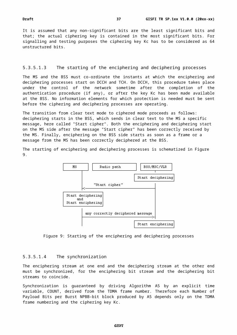
5.4.7 Threats found in open literaturea) Flaws in implementation of A3/A8 algorithms: Although the GSM architecture allows operator to
choose any algorithm for A3 and A8, many operators used COMP128 (or COMP128-1) that was secretly developed by the GSM association, to achieve ‘Security through Obscurity’ [3]. The structure of COMP128 was finally discovered by reverse engineering and some revealed documentations, and many security flaws were subsequently discovered. In addition to the fact that COMP128 makes revealing Ki possible especially when specific challenges are introduced, it deliberately sets ten rightmost bits of Kc equal to zero that makes the deployed cryptographic algorithms 1024 times weaker and more vulnerable, due to the decreased keyspace. Some GSM network operators tried another new algorithm for the A3/A8, called COMP128-2. COMP128-2 was also secretly designed and inherited the problem of decreased keyspace.
b) Subscriber Identity Module (SIM) card cloning: Another important challenge is to derive the root key Ki from the subscriber's SIM. In April 1998, the Smartcard Developer Association (SDA) and the ISAAC research group could find an important vulnerability in the COMP128 algorithm that helped them to extract Ki in eight hours by sending many challenges to the SIM. Ultimately, a side-channel attack, called partitioning attack, was proposed by the IBM researchers that makes attacker capable of extracting Ki if he could access the subscriber's SIM just for one minute. The attacker can then clone the SIM and use it for his fraudulent purposes.
c) Vulnerability to the Denial of Service (DoS) attack [1]: A single attacker is capable of disabling an entire GSM cell via a DoS attack. The attacker can send the CHANNEL REQUEST message to the BSC for several times but he/she does not complete the protocol and requests another signaling channel. Since the number of signaling channels is limited, this leads to a DoS attack. It is feasible since the call setup protocol performs the resource allocations without adequate authentication. [T3b]
d) Vulnerability to replay attacks [1]: The attacker can misuse the previously exchanged messages between the subscriber and network in order to perform the replay attacks. Protocol state machines have been exploited to achieve these attacks. [T1m]
e) Flaws in cryptographic algorithms: Both A5/1 and A5/2 algorithms were developed in secret. The output of A5/1 is the XOR of three Linear Feedback Shift Registers (LFSRs). An efficient attack to A5/1 can be used for a real-time cryptanalysis on a PC. A5/2 is a weakened version of A5/1 initially intended for countries with export control restrictions. It was cryptanalyzed in 2003 and 3GPP forbids the use of A5/2 in handsets since Rel 6. Karsten Nohl demonstrated the breaking of A5/1 after a distributed community project for building rainbow tables for A5/1 completed the construction of a rainbow table. Rainbow tables are large (2TB) sets of data that allow recovery of the encryption key in several seconds. This led to the demonstration of the decryption of a recorded A5/1 protected call in June 2010 [16].
GISFI
GISFI TR SP.1xx V1.0.0 (20xx-xx)37Draft
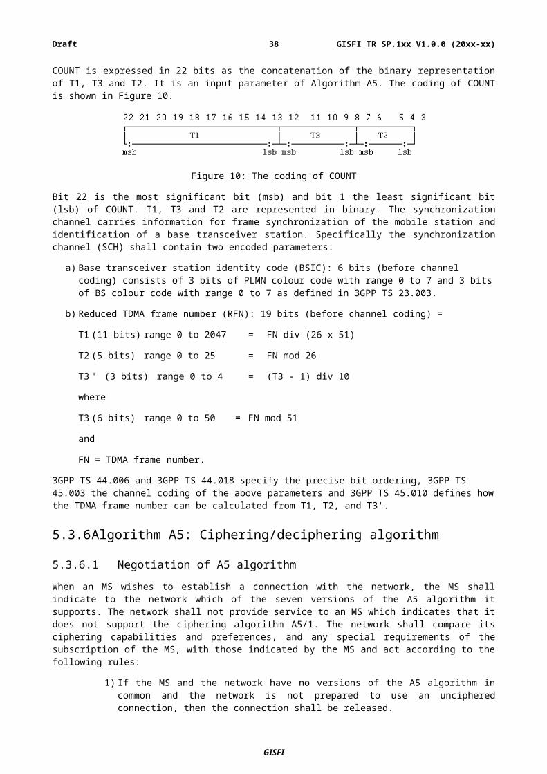
5.4.8 Requirements on security of GSM services addressed by standard
Requirements on protection of personal data:
R1 It shall be possible to protect the confidentiality of certain signalling data and control data, particularly on radio interfaces.
This requirement implies that signalling and control data over the radio interface in GSM needs to be protected through appropriate enciphering procedure. This requirement aims to protect the GSM radio network from two specific threats
T1b Eavesdropping signalling or control data: Intruders may eavesdrop signalling data or control data on the radio interface. This may be used to access security management data or other information which may be useful in conducting active attacks on the system.
T1d Passive traffic analysis: Intruders may observe the time, rate, length, sources or destinations of messages on the radio interface to obtain access to information.
R2 It shall be possible to protect the confidentiality of user traffic, particularly on radio interfaces.
This requirement implies that user traffic such as voice and text messages be protected from eavesdropping through appropriate enciphering scheme on the data channels. This requirement aims to protect the GSM radio network from the following threats:
T1a Eavesdropping user traffic: Intruders may eavesdrop user traffic on the radio interface.
T1c Masquerading as a communications participant: Intruders may masquerade as a network element to intercept user traffic, signalling data or control data on the radio interface.
R3 It shall be possible to protect the confidentiality of user identity data, particularly on radio interfaces.
This requirement implies that the security architecture of the GSM network provides for protection on the user identity data. Especially, in normal conditions the IMSI is not shared on the radio interface.
Requirements on secure service provision:
R4 It shall be possible for service providers to authenticate users at the start of, and during, service delivery to prevent intruders from obtaining unauthorised access to GSM services by masquerade or misuse of priorities.
This requirement implies that GSM provides robust authentication mechanism based on IMSI. Though there are numerous threats possible related to the authorization scheme in GSM, masquerading as another user is one of the major threat over the radio network.
GISFI
GISFI TR SP.1xx V1.0.0 (20xx-xx)38Draft
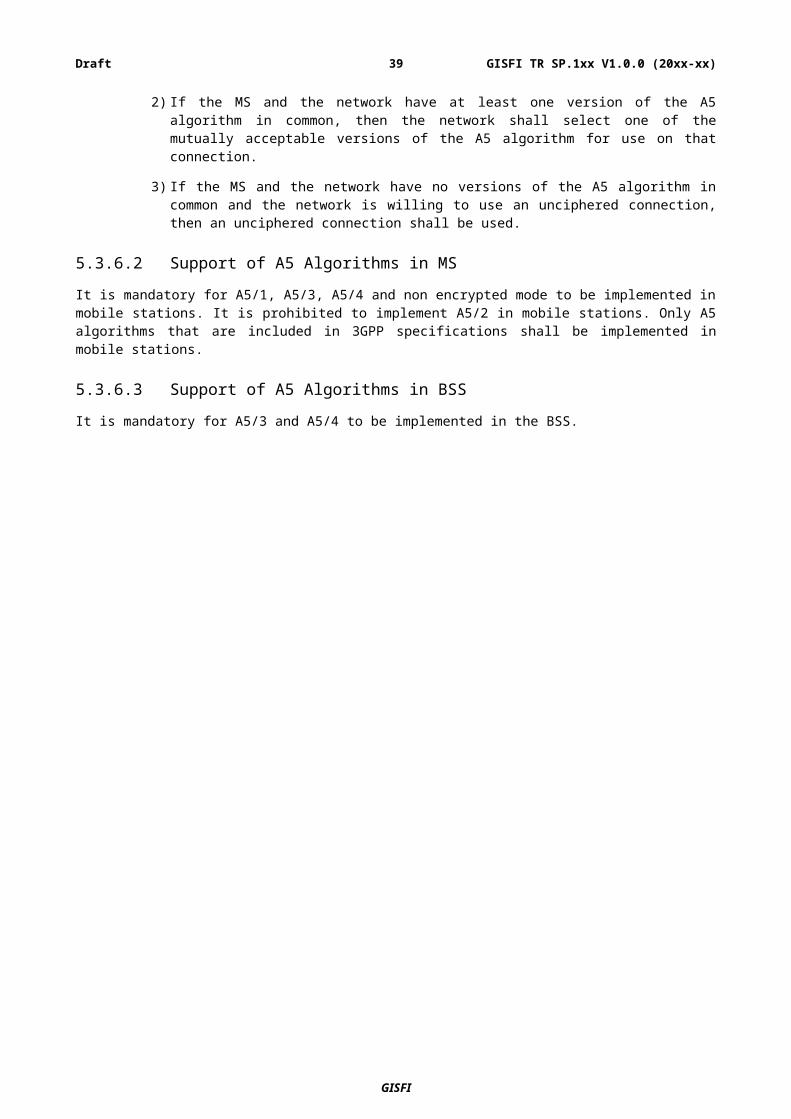
GISFI
GISFI TR SP.1xx V1.0.0 (20xx-xx)39Draft
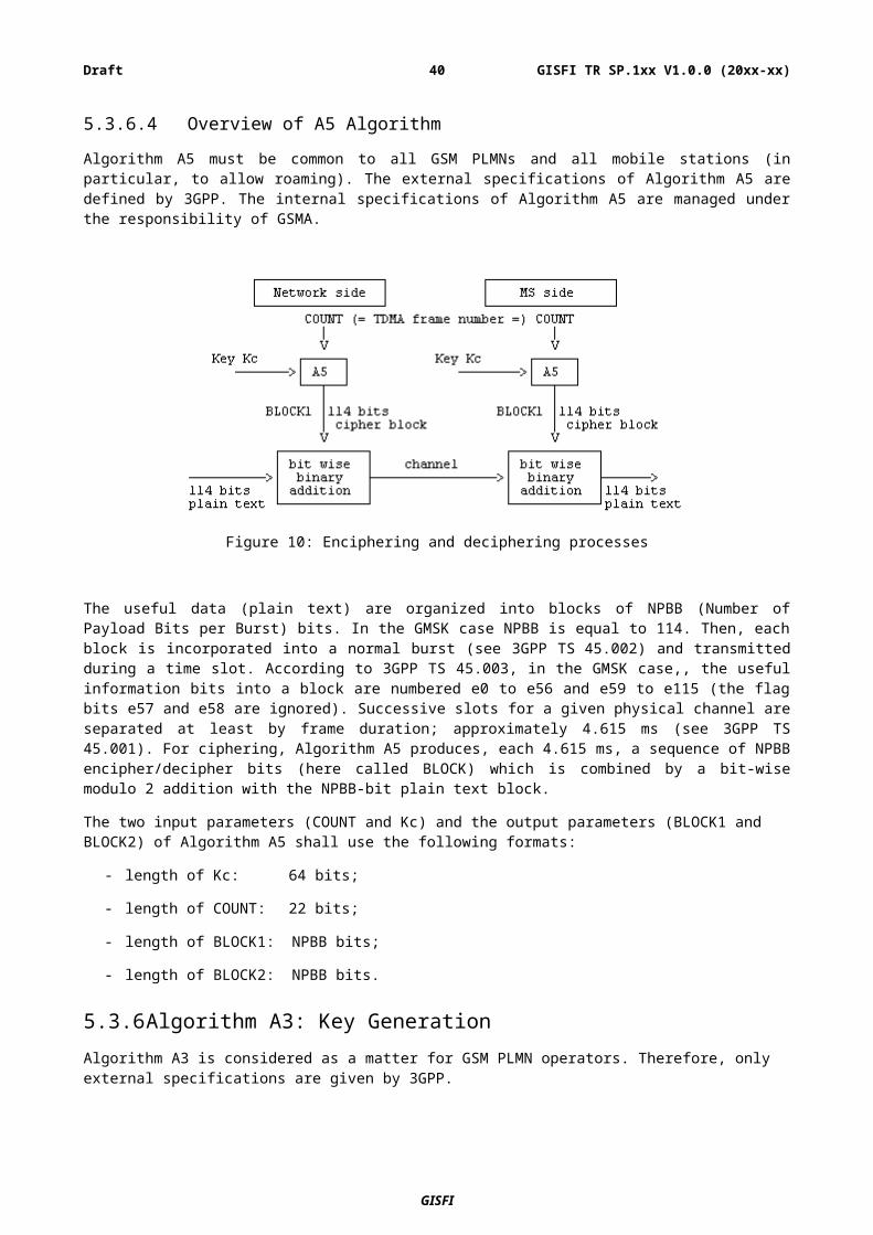
A.1 Heading levels in an annex
GISFI
GISFI TR SP.1xx V1.0.0 (20xx-xx)40Draft
Annex B:Change history:
Change historyDate TSG # TSG Doc. CR Rev Subject/Comment Old New2013-01-10
Initial Draft -
GISFI
GISFI TR SP.1xx V1.0.0 (20xx-xx)41Draft


![GISFI GICT.103 - Global ICT Standardisation Forum · Web view[10] [11] - Reducing Greenhouse Gas Emissions in India Financial mechanisms and opportunities for EU-India < >](https://img.dokumen.tips/doc/110x75/5acb36467f8b9a63398b7820/gisfi-gict103-global-ict-standardisation-view10-11-reducing-greenhouse.jpg)
![GISFI & 5G DEFINITION PROGRAM - Directory Listing dialogue on ICT...1 Future Radio Network & 5G [i2TB] 2 Green ICT ... GISFI 5G DEFINITION PROGRAM 1/2 7 ... CDAC, TEC, DOT, DIETY,](https://img.dokumen.tips/doc/110x75/5abe7d267f8b9a8e3f8d0b1a/gisfi-5g-definition-program-directory-listing-dialogue-on-ict1-future-radio.jpg)