Embed Size (px)
Citation preview

operato
r’s
man
ual
warn
ing:
This
man
ual c
onta
ins
impo
rtant
saf
ety
info
rmat
ion.
Read
man
ual c
aref
ully.
Kee
p m
anua
l with
trai
ler a
t all t
imes
.
drive away with more
operator’s manualfor van and platform trailers
table of contents
Operator’s Instructions ..........................................1
Controlled-Temperature Trailers ............................2
Coupling and Uncoupling ..................................3-7
Proper Use of Steps and Handholds ................8-9
Normal Use ..........................................................10
Weight Distribution for Van Trailers................11-14
Weight Distribution for Platform Trailers........15-16
Procedure for Extending and Closing Extendable Trailers .......................17-18
Pre-Trip Inspection .........................................19-24
Electrical System .................................................25
Wiring Diagram ....................................................26
Fifth Wheel and Kingpin Engagement ................27
Suspension Slider ..........................................27-30
Qwik Release®......................................................29
Brakes and Air Systems.................................31-32
Tires......................................................................32
Tire Loads ............................................................33
Spare Tire.............................................................34
Rims and Wheels ...........................................35-40
Hubs.....................................................................41
Axle Alignment.....................................................42
Leaf-Spring Suspension......................................42
Air-Spring Suspension.........................................42
Exhaust (Dump) Valve Operation ........................43
Supports (Landing Gear) .....................................44
Parking Brakes.....................................................45
Antilock Brake System ........................................46
Rear, Side and Vent Doors.............................47-48
Warranty...............................................................49
Reporting Claims and Safety Defects.................50
Service Record...............................................51-52
Notes....................................................................53
2
This manual has been prepared to assist you in retaining the safety, dependability, and performance that arebuilt into Great Dane trailers. It is essential that this trailer receives periodic inspections, maintenance, andservice parts replacement.
This manual includes safety checks that the operator should perform periodically.
You can get help in setting up your trailer preventative maintenance program from the American TruckingAssociations in Arlington, VA, by contacting ATA through ATA Customer Service at (866) 821-3468, or atwww.atabusinesssolutions.com or www.trucking.org/technolog/council.aspx.
IMPORTANT NOTICEHazard signal words (such as Warning or Caution) appear in various locations
throughout this manual. Additional notes are used to emphasize areas of importance. The following definitions indicate the nature of the consequences of these actions:
operator’s instructions importantRead this manual carefully. Should you have any questions, contact the Great Dane
Customer Service Department immediately for the answers. This manual should be kept with the trailer at all times and should remain with the trailer when it is sold. Replacement manuals Part No. 42101203 can be purchased from Great Dane authorized service parts facilities.
It is important that owners and drivers of controlled-temperature trailers be well informed about the trailers limitations and to operate such trailers within their limitations to ensure safety and profitability of the equipment. Following are some year-around guidelines, which are applicable to controlled- temperature trailers:
1. Do not haul frozen foods in trailer designed only to haul chilled products.
2. Do not install a larger capacity mechanical refrigeration unit in a trailer with inadequate insulation and hope to get the job done.
3. Match trailer insulation performance with refrigeration unit output for highest efficiency.
4. Do not expect the trailer to act as a freezer. Products to be hauled should be loaded at a temperatureas cold as or colder than the required temperature of the products at the time of delivery.
controlled-temperature trailers
caution:Controlled-temperature trailers are designed to transport food and food products.
The vehicle must be clean before loading. DO NOT transport products or use cleaningagents in these trailers that could cause contamination of any food product.
1
warning: Indicates hazards of unsafe practices which could result in serious injury or death.
caution: Indicates hazards of unsafe practices which could result inminor/moderate personal injury and/or damage to property.
4
Step 5: Secure Tractor• Put on the parking brake.• Put transmission in neutral.
Step 6: Check Trailer Coupler Height• The trailer should be low enough that it israised slightly by the tractor when the tractor is backed under it. Raise or lower the trailer asneeded. (If trailer is too low or too high, tractormay strike and damage nose of the trailer, or it may not couple correctly.)
• Check that the kingpin and fifth wheel arealigned.
Step 7: Connect Air Lines to Trailer• Check coupler seals and connect tractor supply (emergency) air line to trailer supply(emergency) coupler.
• Check coupler seals and connect tractor control (service) air line to trailer control (service) coupler.
• Make sure air lines are safely supported wherethey will not be crushed or caught while tractoris backing under the trailer.
Step 8: Supply Air to Trailer• From cab, push in “Air Supply” knob or movetractor protection control valve from the“Emergency” to the “Normal” position to supply air to the trailer brake system.
• Wait until the air pressure is normal.• Check brake system for crossed air lines.– Shut engine off so you can hear leaks in the brake system.
– Apply and release trailer brakes. Listen forsound of trailer brakes being applied andreleased. You should hear the brakes movewhen applied and air escape when thebrakes are released.
– Check air brake system pressure gauge for signs of major air loss.
• When you are sure trailer brakes are working,start engine.
• Make sure air pressure is up to normal
Step 9: Lock Trailer Brakes• Pull out the “Air Supply” knob, or move the tractor protection control valve from “Normal” to “Emergency.”
3
coupling and uncouplingKnowing how to couple and uncouple correctly is basic to the safe operation of combination vehicles.General coupling and uncoupling steps are listed below. There are differences between various combinationsof tractors and trailers. Learn the specific details of coupling and uncoupling the vehicles you will operate.
warning: Incorrect coupling and uncoupling can result in serious injury or death.
Step 1: Inspect Fifth Wheel• Check for damaged/missing parts• Check to see that mounting to tractor is secure,no cracks in frame, etc.
• Be sure that the fifth wheel plate is lubricated as required. Failure to keep the fifth wheel platelubricated could cause steering problemsbecause of friction between the tractor and the trailer.
• Check if fifth wheel is in proper position for coupling:– Wheel tilted down towards rear of tractor.– Jaws open.– Safety unlocking handle in the automatic lock position.
• If you have a sliding fifth wheel, make sure it is locked in place.
• Make sure the trailer kingpin is not damaged.
Step 2: Inspect Area• Make sure area around the vehicle is clear.• Be sure trailer parking brakes are applied.• Check that cargo is secured against movementcaused by the tractor being coupled to the trailer.
Step 3: Position Tractor• Back the tractor directly in front of the trailer.(Never back under the trailer at an angle,because you might push the trailer sidewaysand damage the support legs).
• Check position, using outside mirrors, by looking down both sides of the trailer.
Step 4: Back Slowly• Back until fifth wheel just touches the trailer.• Do not hit the trailer.
COUPLING Tractor-Semi Trailers
6
• With the front of the trailer supported by the tractor, – Check for enough clearance between rear oftractor frame and support legs. (When trac-tor turns sharply it must not hit the supportlegs or their bracing.)
– Check that there is adequate clearancebetween the top of the tractor tires and theunderside of the trailer.
Step 1: Position Rig• Make sure surface of parking area can supportweight of trailer.
• Have tractor in a straight line with the trailer.(Pulling out at an angle can damage the support legs and upper coupler.)
Step 2: Ease Pressure on Locking Jaws• Shut off trailer air supply to lock trailer brakes.• Ease pressure on fifth wheel locking jaws bybacking up gently (this will help you release the fifth wheel locking lever).
• Apply parking brakes while tractor is pushingagainst the kingpin. This will hold the tractorwith pressure off of the locking jaws.
Step 3: Lower the Support Legs• Use high gear range, hold handle carefullyusing two hands and lower the support legsuntil they make firm contact with the ground.Turn crank in low gear a few extra turns. Thiswill lift some weight off the tractor. (Do not lifttrailer off the fifth wheel). This will make it easierto unlatch fifth wheel and couple next time.
5
Step 10: Back Under Trailer• Use lowest reverse gear.• Back tractor slowly under trailer to avoid hittingthe kingpin too hard.
• Stop when the kingpin is locked into the fifth wheel.
Step 11: Check Connection for Security• Raise trailer support legs slightly off ground.• Pull tractor gently forward while the trailerbrakes are still applied.
Step 12: Secure Tractor-Trailer• Put transmission in neutral.• Put parking brakes on.• Shut off engine and take key with you so someone else will not move the tractor-trailer while you are under it.
Step 13: Inspect Coupling• Use a flashlight if necessary.• Make sure there is no space between uppercoupler and fifth wheel. If there is space, something is wrong (kingpin may be on top of closedfifth wheel jaws; trailer can come loose very easily).
• Go under trailer and look into the back of thefifth wheel. Make sure the fifth wheel jaws haveclosed around the shank of the kingpin.
• Check that the locking lever is in the “lock” position.
• Check that the safety catch is in position overlocking lever. (On some fifth wheels the catchmust be put in place by hand.)
• If the coupling is not right, do not drive the coupled unit; get it fixed.
Step 14: Connect the Electrical Cord and Check Air Lines
• Plug the electrical cord into the trailer and fastenthe safety catch.
• Check both air lines and electrical line for signsof damage. Repair or replace if necessary.
• Make sure air and electrical lines will not hit anymoving parts of vehicle.
Step 15: Raise Trailer Support Legs (Landing Gear)
• With two hands on the crank handle, carefullyuse low-gear range (if so equipped) to beginraising the support legs. Once free of weight,switc h to the high-gear range.
• Raise the support legs all the way up. (Neverdrive with support legs only part way up as theymay catch on railroad tracks or other things.)
• After raising the support legs, properly securethe crank handle.
COUPLING Continued
UNCOUPLING Tractor-Semi TrailersThe following steps will help you to uncouple safely.
warning: Incorrect coupling and uncoupling can result in serious injury or death.
Use all steps and handholds with extreme caution. Such components are subject to wear, damage andenvironmental conditions. Make sure these components are firmly attached and properly maintained. If you suspect that they are not, do not use them. If steps are wet, iced or for some reason seem to beslippery, they must not be used.
Steps and handholds are provided on the front wall corners as part of optional vent door packages.They should only be used for access to the vent door. They must not be used to start, inspect or maintain any heating or cooling unit installed on the front wall of the vehicle.
On all models, no attempt should be made to secure a vent in an open position unless the vent holdback is securely installed and functioning.
CLIMBING PRACTICES1. Store clipboards, phones and all other objects prior to climbing. Hands must be free.
2. Face inward (toward the trailer) at all times while ascending and descending.
3. Maintain a three-point contact at all times.
4. Wear slip-resistant footwear.
ACCESS FROM THE GROUNDUse the front wall steps only when the trailer is properly supported by extended support legs. You mustuse a step ladder, or other structure specifically designed for the purpose of ascent and descent, of anadequate height to safely reach the bottommost step.
proper use of steps and handholds
87
An informative video, “Hooking Up Doubles”, showing the TMC recommended method of safely coupling and uncoupling multiple trailers, is available ATA Customer Service 866-821-3468 or www.atabusinesssolutions.com
Step 4: Disconnect Air Lines and Electrical Cable
• Disconnect air lines from trailer. Connect air linecouplers to dummy couplers at back of cab.
• Hang electrical cable with plug down to preventmoisture from entering it.
• Make sure lines are supported so they will notbe damaged while driving the tractor.
Step 5: Unlock Fifth Wheel• Raise release handle lock.• Pull the release handle to “open” position.• Keep legs and feet clear of the rear tractorwheels to avoid serious injury in case the vehicle moves.
Step 6: Pull Tractor Partially Clear of Trailer• Pull tractor forward until fifth wheel comes outfrom under the trailer.
• Stop with tractor frame under trailer (preventstrailer from falling to ground if support legsshould collapse or sink).
Step 7: Secure Tractor• Apply parking brake.• Place transmission in neutral.
Step 8: Inspect Trailer Support• Make sure ground is supporting trailer.• Make sure support legs are not damaged.
Step 9: Pull Tractor Clear of Trailer• Release parking brakes.• Check and drive tractor clear.
UNCOUPLING Continued
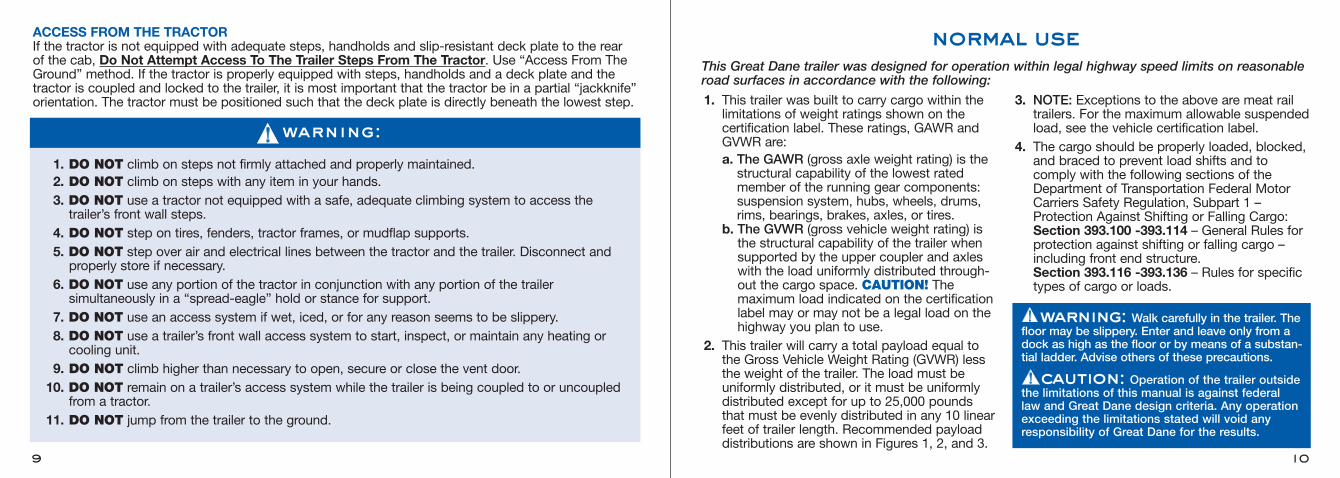
1. This trailer was built to carry cargo within thelimitations of weight ratings shown on the certification label. These ratings, GAWR andGVWR are:a. The GAWR (gross axle weight rating) is thestructural capability of the lowest ratedmember of the running gear components:suspension system, hubs, wheels, drums,rims, bearings, brakes, axles, or tires.
b. The GVWR (gross vehicle weight rating) isthe structural capability of the trailer whensupported by the upper coupler and axleswith the load uniformly distributed through-out the cargo space. CAUTION! Themaximum load indicated on the certificationlabel may or may not be a legal load on thehighway you plan to use.
2. This trailer will carry a total payload equal tothe Gross Vehicle Weight Rating (GVWR) lessthe weight of the trailer. The load must be uniformly distributed, or it must be uniformlydistributed except for up to 25,000 poundsthat must be evenly distributed in any 10 linearfeet of trailer length. Recommended payloaddistributions are shown in Figures 1, 2, and 3.
3. NOTE: Exceptions to the above are meat railtrailers. For the maximum allowable suspendedload, see the vehicle certification label.
4. The cargo should be properly loaded, blocked,and braced to prevent load shifts and to comply with the following sections of theDepartment of Transportation Federal MotorCarriers Safety Regulation, Subpart 1 –Protection Against Shifting or Falling Cargo: Section 393.100 -393.114 – General Rules for protection against shifting or falling cargo – including front end structure.Section 393.116 -393.136 – Rules for specific types of cargo or loads.
normal use
10
ACCESS FROM THE TRACTORIf the tractor is not equipped with adequate steps, handholds and slip-resistant deck plate to the rear of the cab, Do Not Attempt Access To The Trailer Steps From The Tractor. Use “Access From TheGround” method. If the tractor is properly equipped with steps, handholds and a deck plate and thetractor is coupled and locked to the trailer, it is most important that the tractor be in a partial “jackknife”orientation. The tractor must be positioned such that the deck plate is directly beneath the lowest step.
9
warning: Walk carefully in the trailer. Thefloor may be slippery. Enter and leave only from adock as high as the floor or by means of a substan-tial ladder. Advise others of these precautions.
caution: Operation of the trailer outsidethe limitations of this manual is against federal law and Great Dane design criteria. Any operationexceeding the limitations stated will void anyresponsibility of Great Dane for the results.
1. DO NOT climb on steps not firmly attached and properly maintained.2. DO NOT climb on steps with any item in your hands.3. DO NOT use a tractor not equipped with a safe, adequate climbing system to access the trailer’s front wall steps.
4. DO NOT step on tires, fenders, tractor frames, or mudflap supports.5. DO NOT step over air and electrical lines between the tractor and the trailer. Disconnect and properly store if necessary.
6. DO NOT use any portion of the tractor in conjunction with any portion of the trailer simultaneously in a “spread-eagle” hold or stance for support.
7. DO NOT use an access system if wet, iced, or for any reason seems to be slippery.8. DO NOT use a trailer’s front wall access system to start, inspect, or maintain any heating or cooling unit.
9. DO NOT climb higher than necessary to open, secure or close the vent door.10. DO NOT remain on a trailer’s access system while the trailer is being coupled to or uncoupled
from a tractor.11. DO NOT jump from the trailer to the ground.
warning:
This Great Dane trailer was designed for operation within legal highway speed limits on reasonableroad surfaces in accordance with the following:
1211
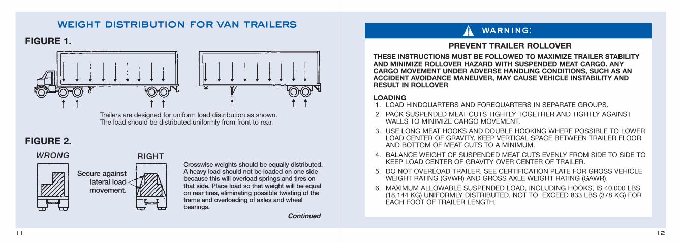
warning:
PREVENT TRAILER ROLLOVERTHESE INSTRUCTIONS MUST BE FOLLOWED TO MAXIMIZE TRAILER STABILITYAND MINIMIZE ROLLOVER HAZARD WITH SUSPENDED MEAT CARGO. ANYCARGO MOVEMENT UNDER ADVERSE HANDLING CONDITIONS, SUCH AS ANACCIDENT AVOIDANCE MANEUVER, MAY CAUSE VEHICLE INSTABILITY ANDRESULT IN ROLLOVER
LOADING1. LOAD HINDQUARTERS AND FOREQUARTERS IN SEPARATE GROUPS.2. PACK SUSPENDED MEAT CUTS TIGHTLY TOGETHER AND TIGHTLY AGAINST
WALLS TO MINIMIZE CARGO MOVEMENT.3. USE LONG MEAT HOOKS AND DOUBLE HOOKING WHERE POSSIBLE TO LOWER
LOAD CENTER OF GRAVITY. KEEP VERTICAL SPACE BETWEEN TRAILER FLOORAND BOTTOM OF MEAT CUTS TO A MINIMUM.
4. BALANCE WEIGHT OF SUSPENDED MEAT CUTS EVENLY FROM SIDE TO SIDE TOKEEP LOAD CENTER OF GRAVITY OVER CENTER OF TRAILER.
5. DO NOT OVERLOAD TRAILER. SEE CERTIFICATION PLATE FOR GROSS VEHICLEWEIGHT RATING (GVWR) AND GROSS AXLE WEIGHT RATING (GAWR).
6. MAXIMUM ALLOWABLE SUSPENDED LOAD, INCLUDING HOOKS, IS 40,000 LBS(18,144 KG) UNIFORMLY DISTRIBUTED, NOT TO EXCEED 833 LBS (378 KG) FOREACH FOOT OF TRAILER LENGTH.
weight distribution for van trailersFIGURE 1.
FIGURE 2.
Trailers are designed for uniform load distribution as shown.The load should be distributed uniformly from front to rear.
Secure againstlateral loadmovement.
Crosswise weights should be equally distributed.A heavy load should not be loaded on one sidebecause this will overload springs and tires onthat side. Place load so that weight will be equalon rear tires, eliminating possible twisting of theframe and overloading of axles and wheel bearings.
WRONG RIGHT
Continued
1413
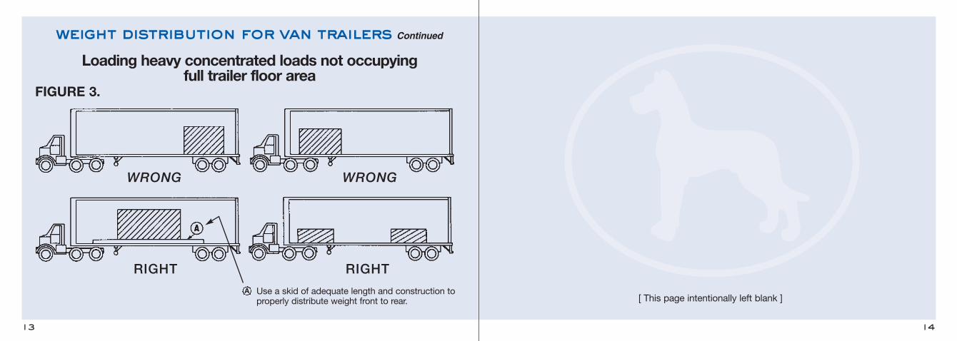
weight distribution for van trailers Continued
FIGURE 3.
WRONG WRONG
RIGHT
Use a skid of adequate length and construction to properly distribute weight front to rear.
RIGHT
A
Loading heavy concentrated loads not occupying full trailer floor area
[ This page intentionally left blank ]
16
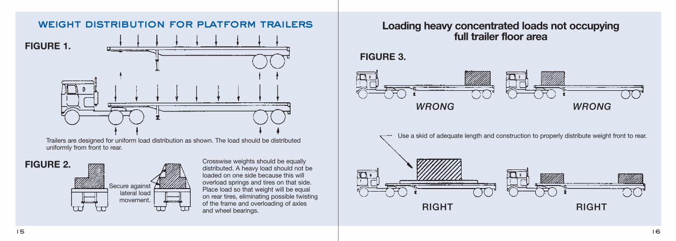
Loading heavy concentrated loads not occupying full trailer floor area
WRONG WRONG
15
weight distribution for platform trailers
FIGURE 1.FIGURE 3.
Trailers are designed for uniform load distribution as shown. The load should be distributeduniformly from front to rear.
Crosswise weights should be equally distributed. A heavy load should not beloaded on one side because this will overload springs and tires on that side.Place load so that weight will be equal on rear tires, eliminating possible twistingof the frame and overloading of axles and wheel bearings.
Secure againstlateral loadmovement.
FIGURE 2.
Use a skid of adequate length and construction to properly distribute weight front to rear.
RIGHT RIGHT
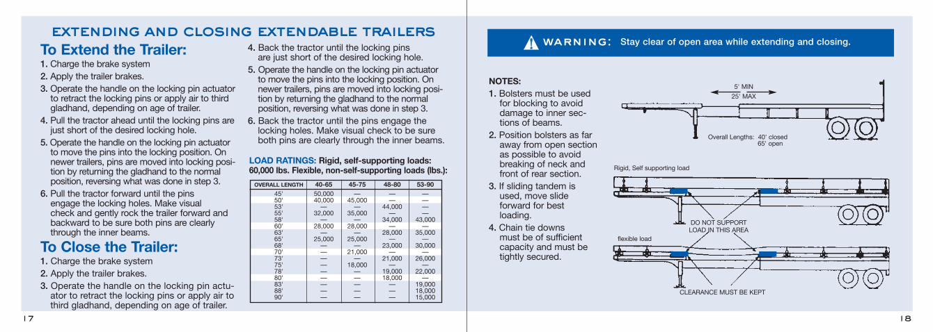
DO NOT SUPPORTLOAD IN THIS AREA
CLEARANCE MUST BE KEPT
NOTES:1. Bolsters must be usedfor blocking to avoiddamage to inner sec-tions of beams.
2. Position bolsters as faraway from open sectionas possible to avoidbreaking of neck andfront of rear section.
3. If sliding tandem isused, move slide forward for best loading.
4. Chain tie downs must be of sufficientcapacity and must betightly secured.
Overall Lengths: 40' closed 65' open
Rigid, Self supporting load
flexible load
5' MIN
25' MAX
18
extending and closing extendable trailers
17
To Extend the Trailer:1. Charge the brake system2. Apply the trailer brakes.3. Operate the handle on the locking pin actuatorto retract the locking pins or apply air to thirdgladhand, depending on age of trailer.
4. Pull the tractor ahead until the locking pins arejust short of the desired locking hole.
5. Operate the handle on the locking pin actuatorto move the pins into the locking position. Onnewer trailers, pins are moved into locking posi-tion by returning the gladhand to the normalposition, reversing what was done in step 3.
6. Pull the tractor forward until the pins engage the locking holes. Make visual check and gently rock the trailer forward andbackward to be sure both pins are clearly through the inner beams.
To Close the Trailer:1. Charge the brake system2. Apply the trailer brakes.3. Operate the handle on the locking pin actu-ator to retract the locking pins or apply air tothird gladhand, depending on age of trailer.
4. Back the tractor until the locking pins are just short of the desired locking hole.
5. Operate the handle on the locking pin actuatorto move the pins into the locking position. Onnewer trailers, pins are moved into locking posi-tion by returning the gladhand to the normalposition, reversing what was done in step 3.
6. Back the tractor until the pins engage thelocking holes. Make visual check to be sureboth pins are clearly through the inner beams.
LOAD RATINGS: Rigid, self-supporting loads: 60,000 lbs. Flexible, non-self-supporting loads (lbs.):
warning: Stay clear of open area while extending and closing.
OVERALL LENGTH 40-65 45-75 48-80 53-9045' 50,000 — — —50' 40,000 45,000 — —53' — — 44,000 —55' 32,000 35,000 — —58' — — 34,000 43,00060' 28,000 28,000 — —63' — — 28,000 35,00065' 25,000 25,000 — —68' — — 23,000 30,00070' — 21,000 — —73' — — 21,000 26,00075' — 18,000 — —78' — — 19,000 22,00080' — — 18,000 —83' — — — 19,00088' — — — 18,00090' — — — 15,000
20
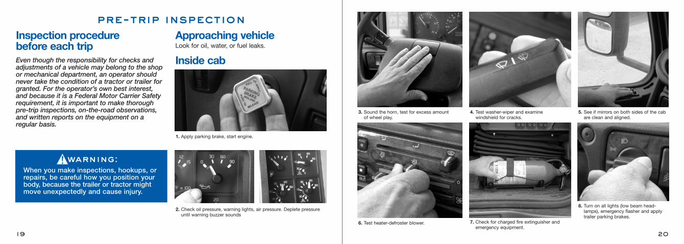
3. Sound the horn, test for excess amountof wheel play.
4. Test washer-wiper and examinewindshield for cracks.
5. See if mirrors on both sides of the cabare clean and aligned.
6. Test heater-defroster blower.
8. Turn on all lights (low beam head-lamps), emergency flasher and applytrailer parking brakes.
7. Check for charged fire extinguisher andemergency equipment.
Inspection procedure before each tripEven though the responsibility for checks andadjustments of a vehicle may belong to the shopor mechanical department, an operator shouldnever take the condition of a tractor or trailer forgranted. For the operator’s own best interest, and because it is a Federal Motor Carrier Safetyrequirement, it is important to make thorough pre-trip inspections, on-the-road observations,and written reports on the equipment on a regular basis.
pre-trip inspection
19
Approaching vehicleLook for oil, water, or fuel leaks.
Inside cab
1. Apply parking brake, start engine.
2. Check oil pressure, warning lights, air pressure. Deplete pressureuntil warning buzzer sounds
warning:When you make inspections, hookups, orrepairs, be careful how you position yourbody, because the trailer or tractor mightmove unexpectedly and cause injury.
22
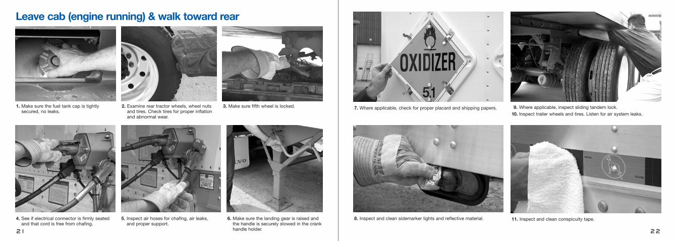
8. Inspect and clean sidemarker lights and reflective material. 11. Inspect and clean conspicuity tape.
7. Where applicable, check for proper placard and shipping papers. 9. Where applicable, inspect sliding tandem lock.10. Inspect trailer wheels and tires. Listen for air system leaks.
21
3. Make sure fifth wheel is locked.
4. See if electrical connector is firmly seatedand that cord is free from chafing.
6. Make sure the landing gear is raised andthe handle is securely stowed in the crankhandle holder.
5. Inspect air hoses for chafing, air leaks,and proper support.
1. Make sure the fuel tank cap is tightlysecured, no leaks.
2. Examine rear tractor wheels, wheel nutsand tires. Check tires for proper inflationand abnormal wear.
Leave cab (engine running) & walk toward rear

24
2. Inspect headlamps, clearance lights, identification lights,flashers, and turn signals.
Front of tractor
1. Inspect front tires, wheels and wheel nuts.
23
1. See if all lights are working properly, and clean as required. 2. Make sure all doors are secured.
Rear of trailer
warning:Most pre-trip inspections are visual.Check electrical wiring, brake hoses and other brake components, distorted orbroken structural components and welds.Report all defects to the proper personsbefore deciding to start your trip.
Back in cab1. Depress dimmer switch, observe high-beam light.
2. With trailer brakes still on, release tractorbrakes and (in first gear) gently engage clutch to test tractor-trailer coupling.
3. Apply foot brake for one minute. Air lossshould not exceed 4 psi per minute for combination rig.
Right side of vehicleInspect lights, conspicuity tape, reflectors, tires,and wheels as was done for the left side.
26
The electrical system on every Great Dane trailermeets or exceeds all federal and state requirementsin effect at the time of manufacture. Whereverrequired by law, lamps and reflective materials aremarked by the manufacturer to indicate the appro-priate specification with which each complies.
For optimum performance and long life from thetrailer’s lamps and wiring, follow this inspectionprocedure.
Clean reflective materials and lamps. See that alllamps burn properly. Replace all burned out lampsand damaged reflective material. Factory approvedreplacement parts should be used, and replace-ment bulbs of equal candlepower should be usedfor safety.
Use only a 12-volt DC battery for checking lampsor antilock brake systems. Never use batterychargers or transformers.
Inspect all wiring to see that it is not frayed, andthat it is properly supported and protected, with allconnections tight. See that the electrical cable isclean and long enough to permit “jackknife”maneuvers. Be certain that the cable is supportedso that it cannot be pinched or entangled by thelower and upper couplers. Keep the plug on theelectrical cable and the receptacle on the trailerfree of corrosion.
electrical system
25
TRAILER IS EQUIPPED WITH ANTILOCK BRAKE SYSTEM (ABS). NO. 7 (BLUE)CIRCUIT IS RESERVED FOR CONTINUOUS POWER SUPPLY TO ABS FOR MOSTEFFECTIVE ABS OPERATION, TOWING VEHICLE MUST SUPPLY MINIMUM OF 10AMPS AT 12.5 VOLTS ON NO. 4 (RED) & NO. 7 (BLUE) CIRCUITS.
PIN COLOR CIRCUIT1 WHITE GROUND RETURN TO TOWING VEHICLE2 BLACK CLEARANCE, SIDE MARKER & ID LAMPS3 YELLOW LEFT TURN SIGNAL & HAZARD LAMPS4 RED STOP LAMPS & ABS POWER5 GREEN RIGHT TURN SIGNAL & HAZARD LAMPS6 BROWN TAIL, LICENSE, CLEARANCE &
SIDE MARKER LAMPS7 BLUE ABS CONTINUOUS SHARED POWER
FAILURE TO HEED THIS WARNING CAN RESULT IN PROPERTY DAMAGE, SERIOUS INJURY OR DEATH.
warning:
J560SOCKET
caution: See Connector Wiring Change caution inside front cover.
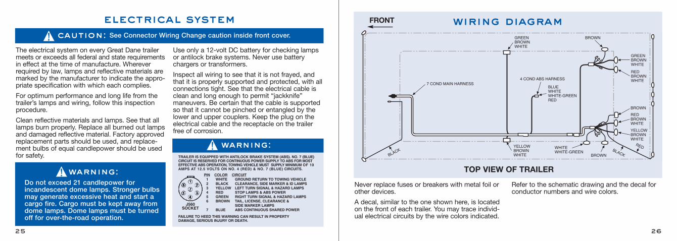
Never replace fuses or breakers with metal foil orother devices.
A decal, similar to the one shown here, is locatedon the front of each trailer. You may trace individ-ual electrical circuits by the wire colors indicated.
Refer to the schematic drawing and the decal forconductor numbers and wire colors.
warning:Do not exceed 21 candlepower for incandescent dome lamps. Stronger bulbsmay generate excessive heat and start acargo fire. Cargo must be kept away fromdome lamps. Dome lamps must be turnedoff for over-the-road operation.
GREENBROWNWHITE
YELLOWBROWNWHITE
WHITEWHITE-GREEN
BROWN
BROWN
GREENBROWNWHITE
REDBROWNWHITE
BROWN
RED
RED
BROWNWHITE
YELLOWBROWNWHITE
7 COND MAIN HARNESS4 COND ABS HARNESS
BLUEWHITEWHITE-GREENRED
FRONT
TOP VIEW OF TRAILER
wiring diagram
28
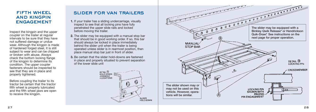
The slider shown may ormay not be used on thisvehicle. However, opera-tions will be similar.
The slider may be equipped with aBinkley Qwik Release® or HendricksonQuik-Draw®. See instructions on the next page for proper operation.
Inspect the kingpin and the upper coupler on the trailer at regularintervals to be sure that they havenot suffered damage or unduewear. Although the kingpin is madeof hardened forged steel, it is stillsubject to wear and can be chippedor broken with abuse. Alwayscheck the bottom locking flange of the kingpin to determine its condition. The upper coupler fasteners should be inspected tosee that they are in place andproperly tightened.
Before coupling the trailer to itstractor be certain that the tractorfifth wheel is properly lubricatedand the fifth wheel jaws are opento receive the kingpin.
fifth wheel and kingpin engagement
27
slider for van trailers1. If your trailer has a sliding undercarriage, visuallyinspect to see that all locking pins have fully penetrated the upper slide rails and locked before moving the trailer.
2. The slider may be equipped with a manual stop barthat should be in good working order. If so, this barshould always be locked in place immediatelybehind the slider unit when the trailer is being operated unless slider is in rearmost position, thenplace manual stop bar just in front of slider.
3. Be certain that the slider hold-downs are fastened in place and properly situated to prevent separationof the lower slide unit
29 30
LOCKING PIN
LOCKING PIN
Qwik Release®
Many sliding running gear assembliesare equipped with Spring-loadedQwik Release device to retract thepins locking the slider frame to theupper rails.
To Position Slider:1. Remove stop bar and move todesired location.
2. Lift pull arm and pull until lockedin the “out” position. If lock pinsdo not retract after pull arm is low-ered in the “out” position, gentlyrock trailer with brakes appliedand pins will automatically retract.
3. Apply trailer brakes and carefullymove trailer until contacting stop bar.
4. Release pull arm to the “in” position and visually check all lock pins for proper engagement.
5. Locate manual stop bar immediately behind slider.
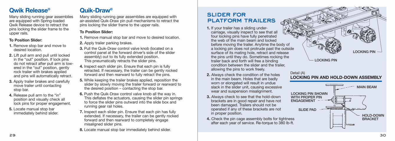
slider for platform trailers1. If your trailer has a sliding under-carriage, visually inspect to see that allfour locking pins have fully penetratedthe web of the main beam and lockedbefore moving the trailer. Anytime the body of a locking pin does not protrude past the outsidesurface of its mating hole, retract and releasethe pins until they do. Sometimes rocking thetrailer back and forth will free a binding condition between the slider and the trailer,allowing the pins to work freely.
2. Always check the condition of the holesin the main beam. Holes that are badlyworn or elongated will result in undueslack in the slider unit, causing excessivewear and suspension misalignment.
3. Always check to see that the hold-down brackets are in good repair and have notbeen damaged. Trailers should not beoperated if any of these brackets are notin proper position.
4. Check the pin cage assembly bolts for tightnessafter each year of service. Re-torque to 380 lb-ft.
LOCKING PIN SHOWNWITH PROPER PIN ENGAGEMENT
SLIDE PAD
HOLD-DOWNBRACKET
MAIN BEAM
Detail (A)LOCKING PIN AND HOLD-DOWN ASSEMBLY
Quik-Draw®
Many sliding running gear assemblies are equipped with air-assisted Quik-Draw pin pull mechanisms to retract the pins locking the slider frame to the upper rails.
To Position Slider:1. Remove manual stop bar and move to desired location.2. Apply trailer parking brakes.3. Pull the Quik-Draw control valve knob (located on a control panel at the forward driver’s side of the sliderassembly) out to its fully extended position. This pneumatically retracts the slider pins.
4. Inspect each slider pin. Ensure that each pin is fully retracted. If necessary, the trailer can be gently rocked forward and then rearward to fully retract the pins.
5. While keeping the trailer brakes applied, reposition theslider by slowly moving the trailer forward or rearward tothe desired position – contacting the stop bar.
6. Push the Quik-Draw control valve knob all the way in. This deflates the actuators, causing the slider pin springsto force the slider pins outward into the slide box and running gear rail holes.
7. Inspect each slider pin. Ensure that each pin has fullyextended. If necessary, the trailer can be gently rockedforward and then rearward to completely engage misaligned slider pins.
8. Locate manual stop bar immediately behind slider.
The trailer brake systems will perform safely andefficiently only as long as you maintain them properlyand do not abuse them. Trailer brakes should beinspected and adjusted frequently in connection
with a Trailer Preventive Maintenance Program. Out-of-adjustment brakes can cause increasedstopping distance, shorter brake component life,and a greater tendency for the trailer to jackknife.
Care and Adjustmentof Brakes
31
Proper operation of the brake systems requires a firm seal between the air brake couplers. Inspect the couplers for seal damage and cracked housings.Inspect the air hoses for cracking and for frayed con-nections. Replace or repair damaged components.
Keep the air system clean. Air tanks should bedrained daily to remove moisture and other contami-nants, especially during cold weather operations.
Use of additives as antifreeze in the air brake systemis not recommended. They may result in deteriorationof valve seals and performance of the brake system.
Keep the air system tight. The air system cannot becharged properly if there are leaks in reservoirs, lines,hoses, or valves. Always check the tractor pressuregauge for unusual drops or extended buildup times.
If you use Teflon tape or other thread sealers to sealthreaded connections in your air lines, be careful notto allow pieces of the sealer to enter the air system.
They can clog passages into the valves.
Run the tractor engine until the air brake systempressure gauge shows at least 105 psi.
With the engine still off, apply the brakes fully for twominutes. The gauge reading drop should not exceedfour psi in one minute.
With the engine still off, slowly open the draincocksin the trailer’s air tanks and allow the pressure todrop gradually. The parking brakes should apply.
Remember that serious air losses are extremely hazardous conditions that are likely to cause accidents or breakdowns.
air system and brake operation
Before entering traffic, check the operation of thetrailer brakes to be sure they are in good workingorder. Operate the foot pedal, dash control valves,
and hand valve to assure brake application andrelease in each instance. Listen for air leaks undereach condition.
check brake operation
32
Do not over inflate. Check for proper inflation with an accurate gauge when the tires are cold. Check the spare too. Inspect tires for nails and other objectsembedded in the rubber, and for stones and otherobjects lodged between duals. Examine tires to seethat they are free of breaks and other defects. Watchnew and retread tires for signs of failure during break-in period. Dual tires on any axle end shouldhave the same diameter. Replace any tire that has fabric exposed through
the tread or sidewall, or that has less than 2/32" tread depth.
tires
NHTSAVehicle Safety Hotline1200 New Jersey Ave. SEWest BuildingWashington, DC 20590Toll Free: 1-866-327-4236
US Department of LaborOSHA Publications Office200 Constitution Ave. NW Washington, DC 202101-800-321-OSHA (6742)
warning:Do not operate this vehicle with any brakedefects or with brakes out of adjustment.
warning:Tire and wheel/rim servicing can beextremely dangerous and must be doneonly by trained personnel using proper toolsand procedures. Information about tire andwheel servicing can be obtained from:
caution:Do not inflate tires above the maximuminflation pressure molded on the tire bythe tire manufacturer. Tires must bematched with proper compatible rims forsafe operation.
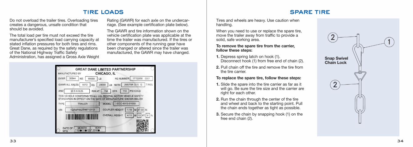
Do not overload the trailer tires. Overloading tirescreates a dangerous, unsafe condition thatshould be avoided.
The total load per tire must not exceed the tiremanufacturer’s specified load carrying capacity atstated inflation pressures for both tires and rims.Great Dane, as required by the safety regulationsof the National Highway Traffic SafetyAdministration, has assigned a Gross Axle Weight
Rating (GAWR) for each axle on the undercar-riage. (See example certification plate below).
The GAWR and tire information shown on thevehicle certification plate was applicable at thetime the trailer was manufactured. If the tires orother components of the running gear have been changed or altered since the trailer wasmanufactured, the GAWR may have changed.
tire loads
33
Tires and wheels are heavy. Use caution when handling.
When you need to use or replace the spare tire,move the trailer away from traffic to provide a solid, safe working area.
To remove the spare tire from the carrier, follow these steps:
1. Depress spring latch on hook (1). Disconnect hook (1) from free end of chain (2).
2. Pull chain off the tire and remove the tire fromthe tire carrier.
To replace the spare tire, follow these steps:
1. Slide the spare into the tire carrier as far as it will go. Be sure the tire size and the carrier areright for each other.
2. Run the chain through the center of the tire and wheel and back to the starting point. Pull the chain ends together as tight as possible.
3. Secure the chain by snapping hook (1) on thefree end chain (2).
spare tire
34
Snap SwivelChain Lock
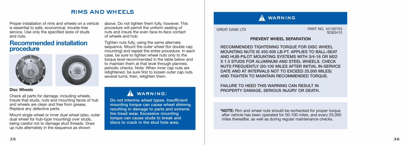
Proper installation of rims and wheels on a vehicleis essential to safe, economical, trouble-free service. Use only the specified sizes of studs and nuts.
Recommended installationprocedure
Disc Wheels
Check all parts for damage, including wheels.Insure that studs, nuts and mounting faces of huband wheels are clean and free from grease.Replace any defective parts.
Mount single wheel or inner dual wheel (also, outerdual wheel for hub-type mounting) over studs,being careful not to damage stud threads. Drawup nuts alternately in the sequence as shown
above. Do not tighten them fully, however. Thisprocedure will permit the uniform seating of nuts and insure the even face-to-face contact of wheels and hub.
Tighten nuts fully, using the same alternatesequence. Mount the outer wheel (for double capmounting) and repeat the entire procedure. In eachcase, be sure to tighten wheel nuts only to thetorque level recommended in the table below andto maintain them at that level through planned,periodic checks. Note: When inner cap nuts areretightened, be sure first to loosen outer cap nutsseveral turns; then, retighten them.
rims and wheels
35 36
*NOTE: Rim and wheel nuts should be rechecked for proper torqueafter vehicle has been operated for 50-100 miles, and every 25,000miles thereafter, as well as during regular maintenance checks.
PREVENT WHEEL SEPARATION
RECOMMENDED TIGHTENING TORQUE FOR DISC WHEELMOUNTING NUTS IS 450-500 LB-FT. APPLIES TO BALL-SEATAND HUB-PILOT MOUNTING SYSTEMS WITH 3/4-16 OR M22X 1.5 STUDS FOR ALUMINUM AND STEEL WHEELS. CHECKNUTS FREQUENTLY (50-100 MILES AFTER INITIAL IN-SERVICEDATE AND AT INTERVALS NOT TO EXCEED 25,000 MILES)AND TIGHTEN TO MAINTAIN RECOMMENDED TORQUE.
FAILURE TO HEED THIS WARNING CAN RESULT IN PROPERTY DAMAGE, SERIOUS INJURY OR DEATH.
GREAT DANE LTD PART NO. 42100753SD83410
warning
110
3
5
72
8
6
4
9
warning:Do not intermix wheel types. Insufficientmounting torque can cause wheel shimmy,resulting in damage to parts and extremetire tread wear. Excessive mountingtorque can cause studs to break anddiscs to crack in the stud hole area.

To maintain the desired torque/tension relationship, it is necessary to renew the lubricant on thethreads and between the nut body and flange. Relubrications should be done any time wheels areremoved for tire repair or replacement, brake service, etc.
An excess of lubricant is notdesirable. It will not improvenut performance, it makes theparts hard to handle, it willattract dirt, and it will causean unsightly appearance ofthe wheel.
Use any lubricant commonlyavailable to the shop–engineoil, WD-40™, anti-seize com-pound such as Permatex™#133A, or spray lube such asLubriplate™ Spray Lube ‘A’.Never-Seez™, although not alubricant, is also satisfactory.
lubrication of flange nuts & studs
37
A key to successful performance of the hub-piloted wheel, hub and drum mounting system is proper installation of the flange nuts. IT IS IMPORTANT to follow the recommendedinstallation instructions, paying particular attention to the sequence of nut tightening.
A. Before installing wheels, generously coat pilot padswith a non-water-based lubricant, and be surethat the drum is positioned on the raised step ofthe pilot pad. One of the hub’s pilot pads shouldbe at the top location. Adjustment of the brakesprior to installation of the wheels helps keepthe drum in proper position.
B. Lubricate the flange nuts and stud threads.Apply two drops of any common lubricant onthe threads, and also in the crevice betweenthe flange nuts body and its attached flange.
C. After positioning wheels on pilot pads, hand startflange nuts. ALL nuts and studs have RIGHTHAND metric threads.
D. Snug top nuts to about 50-100 lb-ft torque. Snugremaining nuts using pattern shown. STARTING AT THETOP will help insure that the drum and wheels seal properlyon their pilots.
E. Check to be certain that the mating surfaces of the wheel(s) and drum are flush.
F. Again, starting with the top nuts, tighten to 450-500 lb-ft using the pattern shown.
nut tightening procedure
PILOT PADS
TOP
38
Be sure to keep nut flange face and wheel and drum surfaces (denoted by "X") free from lubricant, dirt or other foreign material.WARNING!
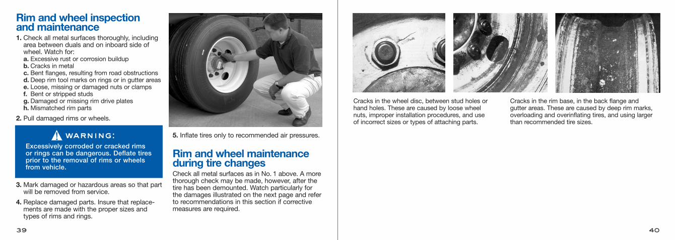
Rim and wheel inspection and maintenance 1. Check all metal surfaces thoroughly, includingarea between duals and on inboard side ofwheel. Watch for:a. Excessive rust or corrosion buildupb. Cracks in metalc. Bent flanges, resulting from road obstructionsd. Deep rim tool marks on rings or in gutter arease. Loose, missing or damaged nuts or clampsf. Bent or stripped studsg. Damaged or missing rim drive platesh.Mismatched rim parts
2. Pull damaged rims or wheels.
3. Mark damaged or hazardous areas so that partwill be removed from service.
4. Replace damaged parts. Insure that replace-ments are made with the proper sizes and types of rims and rings.
5. Inflate tires only to recommended air pressures.
Rim and wheel maintenanceduring tire changesCheck all metal surfaces as in No. 1 above. A morethorough check may be made, however, after thetire has been demounted. Watch particularly forthe damages illustrated on the next page and referto recommendations in this section if correctivemeasures are required.
39
Cracks in the wheel disc, between stud holes orhand holes. These are caused by loose wheel nuts, improper installation procedures, and use of incorrect sizes or types of attaching parts.
Cracks in the rim base, in the back flange and gutter areas. These are caused by deep rim marks,overloading and overinflating tires, and using largerthan recommended tire sizes.
40
warning:Excessively corroded or cracked rimsor rings can be dangerous. Deflate tiresprior to the removal of rims or wheelsfrom vehicle.
Check the equalizer to see that there are no obstruc-tions to movement during operation. If equalizermovement is restricted by an obstruction, the axle“walk” will not be sufficient and damage will result.
Check wear pads in hangers. If they are wearing thin, install new wear pads or the spring will causepermanent damage to the hanger. Do not operatewith broken spring leaves.
leaf-spring suspension
The air suspension height is controlled by heightcontrol valves that maintain a constant trailerheight by pressurizing or exhausting air in the air springs as needed to support the load beingcarried.You must build up and maintain your trailer’s air pressure higher that 70 psi before operating thetrailer. The air protection valve won’t operate untilyou have 70 psi in the system. This valve automati-cally maintains a safe air brake pressure higherthan 70 psi in the event of an air loss due to a failure in the suspension system.
If an air-spring failure occurs on one side, it is recommended to completely deflate the suspensionand temporarily operate on the air springs’ internalrubber bumpers to allow your trailer to be movedto a shop for repairs.To deflate or cut off the air pressure to the damagedair spring, disconnect the height control valveactuating levers from their link assemblies androtate to the vertical down position.
air-spring suspension
Axle alignment must be checked at regular intervals. If the trailer is not tracking properly, this should bereported to the Maintenance Department.
axle alignment
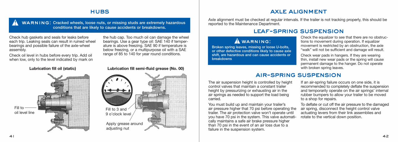
Check hub gaskets and seals for leaks beforeeach trip. Leaking seals can result in ruined wheelbearings and possible failure of the axle-wheelassembly.Check oil level in hubs before every trip. Add oilwhen low, only to the level indicated by mark on
the hub cap. Too much oil can damage the wheelbearings. Use a gear type oil: SAE 140 if temper-ature is above freezing. SAE 90 if temperature isbelow freezing, or a multipurpose oil with a SAErange of 85 to 140 for year round conditions.
hubs
41
Fill to oil level line
Apply grease around adjusting nut
Lubrication fill oil (static) Lubrication fill semi-fluid grease (No. 00)
Fill to 3 and 9 o’clock level
warning: Cracked wheels, loose nuts, or missing studs are extremely hazardousconditions that are likely to cause accidents or breakdowns.
warning:Broken spring leaves, missing or loose U-bolts,or other defective conditions likely to cause axleshift, are hazardous and can cause accidents orbreakdowns
42
43
In many cases trailers that are equipped with airsuspensions also incorporate valving that allowsthe suspensions’ air pressure to be manuallyexhausted (dumped) for loading, unloading, orwhen the trailer is parked for a prolonged periodof time. The following steps describe a typicalsequence of operations involving the use of apneumatically or electrically controlled exhaust(dump) valve:To Exhaust1. Pull the trailer forward past the loading dock.2. Activate the exhaust valve using either thepneumatic or electric switch provided by theinstaller.
3. Back the trailer to the dock area, allowing thesuspensions to exhaust as you move rear-ward.
4. Apply the trailer’s parking brakes after the airpressure has completely exhausted, chock thetrailer wheels and load/unload as you normallywould.
(NOTE:) Lower the trailer support legs (landinggear) after applying the parking brakes if the tractor is to be uncoupled.
To Inflate1. Couple the tractor and trailer.2. Raise the support legs prior to inflating the suspension’s air springs.
3. Un-chock the wheels, release the parkingbrakes and pull away from the dock.
4. Activate the exhaust (dump) valve using thepneumatic or electric switch.
The steps listed above will prevent the trailer from“walking” away from the dock during loading orunloading. To accomplish this, and to avoid damaging the trailer and suspension components,the following conditions must be met:• The suspensions’ air pressure must be exhausted BEFORE the brakes are applied.
• ALL of the trailer air suspensions must beexhausted.
• The suspensions must be properly inflatedBEFORE the trailer is driven away.
Following the steps listed above will satisfy theseconditions and ensure the safe operation of thetrailer air suspensions.
exhaust (dump) valve operation
44
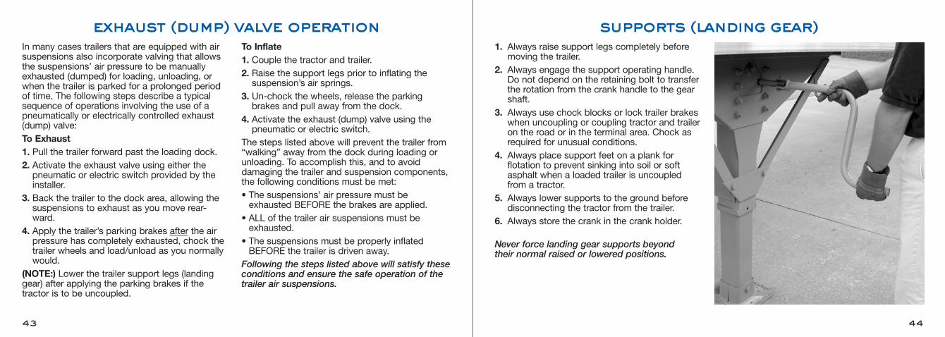
1. Always raise support legs completely before moving the trailer.
2. Always engage the support operating handle. Do not depend on the retaining bolt to transferthe rotation from the crank handle to the gearshaft.
3. Always use chock blocks or lock trailer brakeswhen uncoupling or coupling tractor and traileron the road or in the terminal area. Chock asrequired for unusual conditions.
4. Always place support feet on a plank for flotation to prevent sinking into soil or softasphalt when a loaded trailer is uncoupled from a tractor.
5. Always lower supports to the ground before disconnecting the tractor from the trailer.
6. Always store the crank in the crank holder.
Never force landing gear supports beyond their normal raised or lowered positions.
supports (landing gear)
46
antilock brake system
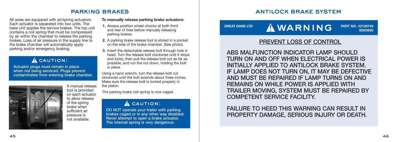
PREVENT LOSS OF CONTROL
ABS MALFUNCTION INDICATOR LAMP SHOULDTURN ON AND OFF WHEN ELECTRICAL POWER ISINITIALLY APPLIED TO ANTILOCK BRAKE SYSTEM. IF LAMP DOES NOT TURN ON, IT MAY BE DEFECTIVEAND MUST BE REPAIRED IF LAMP TURNS ON ANDREMAINS ON WHILE POWER IS APPLIED WITHTRAILER MOVING, SYSTEM MUST BE REPAIRED BYCOMPETENT SERVICE FACILITY.
FAILURE TO HEED THIS WARNING CAN RESULT INPROPERTY DAMAGE, SERIOUS INJURY OR DEATH.
GREAT DANE LTD PART NO. 42100749SD83830warning
parking brakesAll axles are equipped with air/spring actuators.Each actuator is separated into two units. Thebase unit applies the service brakes. The top unitcontains a coil spring that must be compressedby air within the chamber to release the parkingbrakes. Loss of air pressure in the supply line tothe brake chamber will automatically apply parking and/or emergency braking.
A manual releasetool is providedon each actuatorto allow releaseof the springbrake when sufficient airpressure is not available.
To manually release parking brake actuators:
1. Always position wheel chocks at both front and rear of tires before manually releasing parking brakes.
2. A parking brake release tool is stored in a pocketon the side of the brake chamber. (See photo).
3. Insert the detachable release bolt through hole inhead. Turn the release bolt clockwise until it stopsand locks, then pull the release bolt out as far aspossible, and run the nut down, holding the bolt in place.
Using a hand wrench, turn the release bolt nut clockwise until the bolt extends about three inches.Make sure the release bolt is locked properly in the piston.
The parking brake coil spring is now caged.
45
caution:Actuator plugs must remain in place when not being serviced. Plugs prevent contaminates from entering brake chamber.
caution:DO NOT operate your trailer with parkingbrakes caged or in any other way disabled.Never attempt to open a brake actuator.The internal spring is very dangerous.
48
rear, side and vent doors
47
1. Check rear, side, vent, and any accessory doors.Secure them open or closed as required.
2. Never have side or rear doors unlocked or openwhen the trailer is moving.
Swing Doors
Overhead Doors
To assure safe, reliable, and continuous operation, the following precautions and maintenance instructions must be observed.1. Operate the door only when it is properly adjustedand free from obstruction.
2. Do not use any part of the door, such as the strapor lift handle, as an aid when entering or leavingthe trailer.
3. Use caution when passing under a roll-up doorwith a lift truck.
4. Leave the door alone if it becomes difficult orimpossible to operate. Have it repaired or adjusted by a qualified door repair person.
5. The door spring is constantly under extreme tension. Repairs and adjustments, especially to the door counterbalance assembly, are potentiallydangerous and must be performed by qualifiedservice personnel only.
6. Clear any obstruction from the door tracks and thebase of the mounting angle where the door comesdown to the floor.
7. Perform regular inspection and maintenance on the listed items:a. Be certain that all nuts and bolts are tight and secure.
b. Check cables at attachment points and replaceall frayed or otherwise damaged cable.
c. Check cable drums for tightness against bearings.
d. Check all rollers for smoothness of operation,and have all sliding or otherwise damagedrollers replaced.
e. Replace frayed, damaged, or severely worn pull straps.
f. Check the door lock to be sure that it is free,and fully operational.
g. Replace broken or damaged hinges.h. Periodically use a light lubricant (not grease) on rollers, counterbalance hinges, and lock, as necessary, to maintain a smooth door operation.
Bulkheads
caution:When you open side or rear doors, at alltimes apply an inward pressure on the doorhandle when releasing the handle from thegravity keeper. This may prevent a toppledload from snapping open the door handle,perhaps causing serious injury.
caution:When in operation, an overhead door is alarge, heavy moving object. When the dooris moving up or down, avoid standing in theopening or walking through the doorway.
caution:Close and lock overhead door before moving the trailer.
caution:Do not operate the trailer with a bulkheadlocked in the horizontal position. Do notuse the bulkhead as a load shifting barrieror brace.
First purchaser warranty claims andother consumer complaints shouldbe reported in writing to:
Customer Service Department Great Dane Limited Partnership P.O. Box 67Savannah, GA 31402-0067
or call 877-369-3493
49 50
This vehicle was designed and quality inspectedto conform with industry standards, and all applicable National Highway Traffic SafetyAdministration (NHTSA) safety standards. Great Dane Limited Partnership warrants this vehicle to be free from defects in materials andworkmanship when manufactured. If you detect a defect that could cause an accident, injury ordeath; or if you wish to report any such accident,injury or death, or any property damage claim orother complaint not addressed to the CustomerService Department, then you should in writingadvise:
Director, Customer ServiceGreat Dane Limited Partnership
P.O. Box 67Savannah, GA 31402-0067
If you believe that your vehicle has a defect which could cause a crash or could cause injuryor death, you should immediately inform NHTSA in addition to notifying Great Dane Limited Partnership.
If NHTSA receives similar complaints, it may openan investigation, and if it finds that a safety defectexists in a group of vehicles, it may order a recalland remedy campaign. However, NHTSA cannotbecome involved in individual problems betweenyou, your dealer, or Great Dane Limited Partnership.
To contact NHTSA, you may call the VehicleSafety Hotline toll-free at 1-888-327-4236 (TTY:1-800-424-9153); go to http://www.safercar.gov;or write to:
Administrator, NHTSA, 1200 New Jersey Ave. SEWest BuildingWashington, DC 20590
You can also obtain information about motorvehicle safety from http://www.safercar.gov.
reporting claims and safety defects
warranty claims Customer Service Phone Number: 877-369-3493

51 52
DATE MILEAGE DESCRIPTION
service recordDATE MILEAGE DESCRIPTION
service record

53
notes
54
notes
55
notes
refer to the great dane maintenance manual
before performing any repair, service or
procedure.
56

683 DM
D 0117
Great Dane and the oval are registered trademarks of Great Dane Lim
ited Partnership.
www.greatdanetrai lers .com
drive away with morePart No. 42101203