Embed Size (px)
Citation preview
FutabaDIGITAL PROPORTIONALRADIO CONTROL
PCMPULSE CODE MODULATION SYSTEM
INSTRUCTION MANUALFP-8SGAPPCM 8 CHANNELS,FOR F3A AIRCRAFT
D60354

Thank you for purchasing a Futabadigital proportional radio control set.
Please read this manual carefully before using your set.
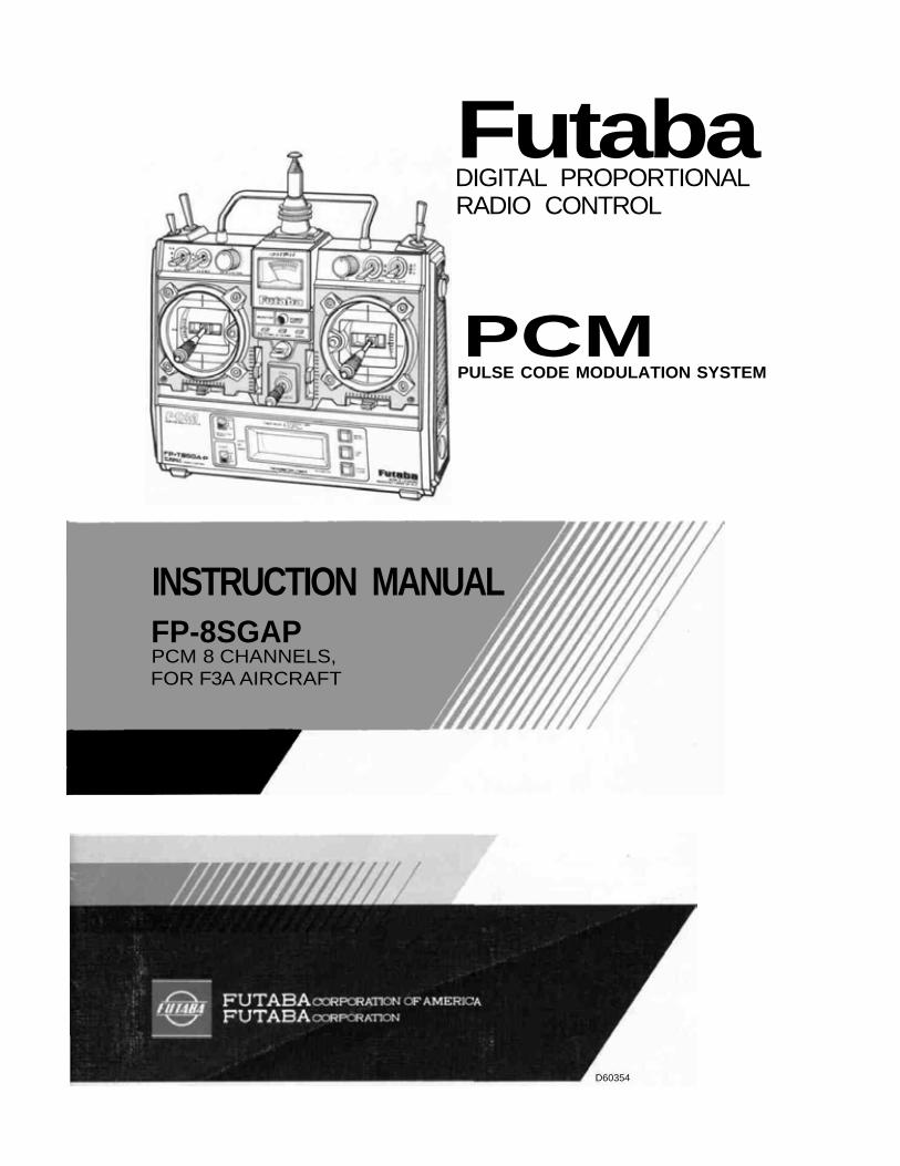
TABLE OF CONTENTS INDEX FOR TRIMMER PANEL FUNCTIONS
GENERAL INFORMATIONFeatures . . . . . . . . . . . . . . . . . . . . . . . . . . . .Contents and Ratings . . . . . . . . . . . . . . . . . . . .Glossary of Terms . . . . . . . . . . . . . . . . . . . . . .Basic Transmitter Controls . . . . . . . . . . . . . . . . .
Batteries and Charging Instructions . . . . . . . . . . . .Tachometer/Timer Operation . . . . . . . . . . . . . . . . .
Receiver and Servos . . . . . . . . . . . . . . . . . . . . . .
FP S130 and FP-S130G Exploded Views . . . . . . . . . .
Splined Horns. . . . . . . . . . . . . . . . . . . . . . . . . .
ADJUSTMENTS AND F L I G H T TECHNIQUESBasic Linkages and Installation . . . . . . . . . . . . . . .
Using ATV (Adjustable Travel Volume) . . . . . . . . . . .2ND ATV (Conventional) . . . . . . . . . . . . . . . . . . .
Servo Reversing Switches . . . . . . . . . . . . . . . . . . .Using Dual Rate (Aileron, Elevator, and Rudder) . . . . .Rudder Auto Dual Rate . . . . . . . . . . . . . . . . . . . .Using VTR (Variable Trace Ratio) . . . . . . . . . . . . . .Suggestions on ATV, D/R. and VTR . . . . . . . . . . . . .Using ATL (Adjustable Throttle Limit) . . . . . . . . . . .FS (Fail Safe) and HOLD Functions . . . . . . . . . . . . .BFS (Battery Fail Safe) and BFS Memory . . . . . . . . .Servo Test Functions . . . . . . . . . . . . . . . . . . . . . .Aircraft with Variable Pitch Prop . . . . . . . . . . . . . .Throttle Position Trimmer . . . . . . . . . . . . . . . . . .
Aircraft with Flaps . . . . . . . . . . . . . . . . . . . . . . .Elevator/Flap Mixing . . . . . . . . . . . . . . . . . . . . .
Flap/Elevator Mixing (Pre-Set Flaps and Elev. T r i m ) . . . .Aircraft with Flaps and Spoilers (Airbrake) . . . . . . . . .Flap Trim Function . . . . . . . . . . . . . . . . . . . . . .Snap Roll Switch . . . . . . . . . . . . . . . . . . . . . . . .Programmable Mixing and Examples. . . . . . . . . . . . .Mutual (Bi-directional) Mixing (FLPRON,ELEVN, V TAIL, DIFF) . . . . . . . . . . . . . . . . . . .
1 Aileron Dual Rate 1 Trimmer . . . . . . . . . . . . . .2 Aileron Dual Rate 2 Trimmer . . . . . . . . . . . . . .3 Aileron Linear/VTR Safety Switch . . . . . . . . . .4 Throttle Delay Trimmer . . . . . . . . . . . . . . . . .5 Pitch Delay Trimmer . . . . . . . . . . . . . . . . . . .6 Throttle/Pitch Mixing Trimmer . . . . . . . . . . . . .7 Throttle/Pitch Mixing Safety Switch . . . . . . . . . .8 Throttle Position Trimmer . . . . . . . . . . . . . . .9 Elevator Flap Mixing Trimmer . . . . . . . . . . . . .
10 Elevator Flap Mixing Safety Switch . . . . . . . . . .11 & 12 Programmable Mixing Rate Trimmers . . . . .13 Slave Channel Mixing Board . . . . . . . . . . . . . .14 Master Channel Mixing Board . . . . . . . . . . . . . .15 Aileron Differential Trimmer . . . . . . . . . . . . . .16 ELEVN/V. Tail Mixing Switch . . . . . . . . . . . . .
17 FLPRON/DIFF Mixing Switch . . . . . . . . . . . . .18 Flap Switch . . . . . . . . . . . . . . . . . . . . . . . .19 Airbrake Elevator Trimmer . . . . . . . . . . . . . . .
20 Airbrake Flap Trimmer . . . . . . . . . . . . . . . . .21 Rudder Dual Rate Trimmer . . . . . . . . . . . . . . .
22 Rudder Linear/VTR Safety Switch . . . . . . . . . .23 Elevator Dual Rate Trimmer . . . . . . . . . . . . . .24 Elevator Linear/VTR Safety Switch . . . . . . . . . .
25-28 Snap Roll Timer Setting Trimmers (Optional) . .29 Snap Roll Safety Switch . . . . . . . . . . . . . . . . .30 Switch 16 Function Select Switch . . . . . . . . . . .31 Automatic Dual Rate Rudder Safety Switch . . . . . .32 Flap, Spoiler Elevator Mixing Switch . . . . . . . . . .
33 Throttle Flap, Spoiler Elevator Mixing Switch . . . . ,
34-35 Aileron 2ND ATV Trimmers . . . . . . . . . . . . .36-37 Elevator 2ND ATV Trimmer . . . . . . . . . . . . .38-45 Servo Reversing Switches . . . . . . . . . . . . . . .46-47 ATV/FS Buttons . . . . . . . . . . . . . . . . . . . .48 Channel Select Switch . . . . . . . . . . . . . . . . . . .49 Function Select Switch . . . . . . . . . . . . . . . . . .
Switch or Description Ref. PageTrimmerNumber
NOTE:Please read and follow instructions for installation and usage in their entirety andfollow carefully. Failure to follow instructions could result in serious propertydamage and/or personal injury. This system is intended for use by experiencedR/C hobbyists. Beginners should seek expert advice and Assistance before operat-ing this system.
•FEATURESThe FP-8SGAP was specially developed to use PCM (pulse code modulation) for FAIRC aerobatics F3A aircraft. It is an extremely noise and dead-point resistant digitalproportional RC set with a microprocessor in the transmitter and the receiver. Pleaseread this manual before using your set.
TRANSMITTER FP-T8SGAP
• RF module system. The frequency band can bechanged with one touch.
• DSC (Direct Servo Controller) allows operationof the servos without turning on the transmitter.Wire operation is possible by using the specialcord supplied (FSC.1)
•Servo reversing switch for all channels allowsreversing of the servos with the flip of a switch.
• Dual rate or non-linear VTR (variable traceratio) aileron, elevator, and rudder. Two-stagedual rate on aileron.
• Rudder auto dual rate. Rudder dual rate is turn-ed on and off automatically with operation ofthe throttle stick.
• Newly designed slantable open gimbal sticksprovide maximum operation feel. Stick angleand spring strength can be adjusted.
• Non-slip adjustable lever head. The stick lengthcan be adjusted by turning the knob head.
• New throttle -> pitch control mixing is perfectfor variable pitch propeller which maximizesengine power and propeller efficiency.
•Mutual mixing function allows aileron + eleva-tor, aileron + flaps, and aileron + rudder mixingand aileron differential operation.
• Elevator -> flap mixing is especially advantageousin circle aerobatics.
• Flap, spoiler -> elevator mixing allows control ofthe aircraft attitude while using the air brake(flap, spoiler).
• Throttle -> (flap, spoiler) -> elevator mixing al-lows enhancement of the air braking effect bythrottle stick operation when diving and landing.
• Programmable mixing function permits mixingwith the desired channel.
• Four-function snap roll switch (timer is option-al)
• Idle-up lever, the engine idling speed can beindependently adjusted during throttle -> pitchcontrol mixing.
• New single-chip microprocessor allows one-touchfail safe setting and introduction of an automatictransmission system which eliminates the needfor fail safe setting at the beginning of eachflight and improves safety.
•Pitch control lever. HIGH side pitch of variablepitch propeller can be adjusted during throttle ->pitch control mixing.
• New ATV (Adjustable Travel Volume) on allchannels allows independent adjustment of servoleft, right, up, and down throw.
•Second ATV. Besides new pushbutton ATV onaileron and elevator, conventional trimmer ATVis also installed.
• Monitor lamp comes on when throttle -> flap,spoiler -> elevator mixing or throttle -> pitchcontrol mixing and flap, spoiler -> elevator mix-ing and snap roll are set and goes out when theyare in use.
• Fail-safe switch (function OFF switch) is provid-ed for each function so that only the desiredfunctions need be turned on.
•Throttle ATL (Adjustable Throttle Limiter)makes throttle linkage simple and positive.
• Two servo test functions. A slow sweep to checkneutral characteristic, trackability cycle servo totest servo operation.
•Tachometer/timer with built-in tachometer, uptimer, down timer, integrating timers, and bat-tery alarm functions.
• Built-in power error back-up circuit. When theinternal Nicd battery approaches the fully dis-charged state, an LED flashes to indicate thatthe memories presetted (memory, ATV, FS,etc.) are gone. Please charge battery and set allmemory functions again.
• Highest quality extruded aluminum case. So-phisticated transmitter design gives easy fitnessand comfortable feeling to your hands.
• Neck strap supplied as a standard accessory. Thenumerous functions of the transmitter can beeasily performed by supporting the transmitterfrom your neck.
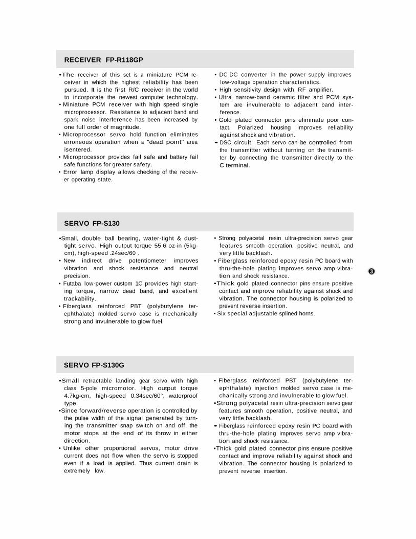
RECEIVER FP-R118GP
•The receiver of this set is a miniature PCM re-ceiver in which the highest reliability has beenpursued. It is the first R/C receiver in the worldto incorporate the newest computer technology.
• Miniature PCM receiver with high speed singlemicroprocessor. Resistance to adjacent band andspark noise interference has been increased byone full order of magnitude.
• Microprocessor servo hold function eliminateserroneous operation when a "dead point" areais entered.
• Microprocessor provides fail safe and battery failsafe functions for greater safety.
• Error lamp display allows checking of the receiv-er operating state.
• DC-DC converter in the power supply improveslow-voltage operation characteristics.
• High sensitivity design with RF amplifier.• Ultra narrow-band ceramic filter and PCM sys-
tem are invulnerable to adjacent band inter-ference.
• Gold plated connector pins eliminate poor con-tact. Polarized housing improves reliabilityagainst shock and vibration.
• DSC circuit. Each servo can be controlled fromthe transmitter without turning on the transmit-ter by connecting the transmitter directly to theC terminal.
SERVO FP-S130
•Small, double ball bearing, water-tight & dust-tight servo. High output torque 55.6 oz-in (5kg-cm), high-speed .24sec/60 .
• New indirect drive potentiometer improvesvibration and shock resistance and neutralprecision.
• Futaba low-power custom 1C provides high start-ing torque, narrow dead band, and excellenttrackability.
• Fiberglass reinforced PBT (polybutylene ter-ephthalate) molded servo case is mechanicallystrong and invulnerable to glow fuel.
• Strong polyacetal resin ultra-precision servo gearfeatures smooth operation, positive neutral, andvery little backlash.
• Fiberglass reinforced epoxy resin PC board withthru-the-hole plating improves servo amp vibra-tion and shock resistance.
•Thick gold plated connector pins ensure positivecontact and improve reliability against shock andvibration. The connector housing is polarized toprevent reverse insertion.
• Six special adjustable splined horns.
SERVO FP-S130G
•Small retractable landing gear servo with highclass 5-pole micromotor. High output torque4.7kg-cm, high-speed 0.34sec/60°, waterprooftype.
•Since forward/reverse operation is controlled bythe pulse width of the signal generated by turn-ing the transmitter snap switch on and off, themotor stops at the end of its throw in eitherdirection.
• Unlike other proportional servos, motor drivecurrent does not flow when the servo is stoppedeven if a load is applied. Thus current drain isextremely low.
• Fiberglass reinforced PBT (polybutylene ter-ephthalate) injection molded servo case is me-chanically strong and invulnerable to glow fuel.
•Strong polyacetal resin ultra-precision servo gearfeatures smooth operation, positive neutral, andvery little backlash.
• Fiberglass reinforced epoxy resin PC board withthru-the-hole plating improves servo amp vibra-tion and shock resistance.
•Thick gold plated connector pins ensure positivecontact and improve reliability against shock andvibration. The connector housing is polarized toprevent reverse insertion.
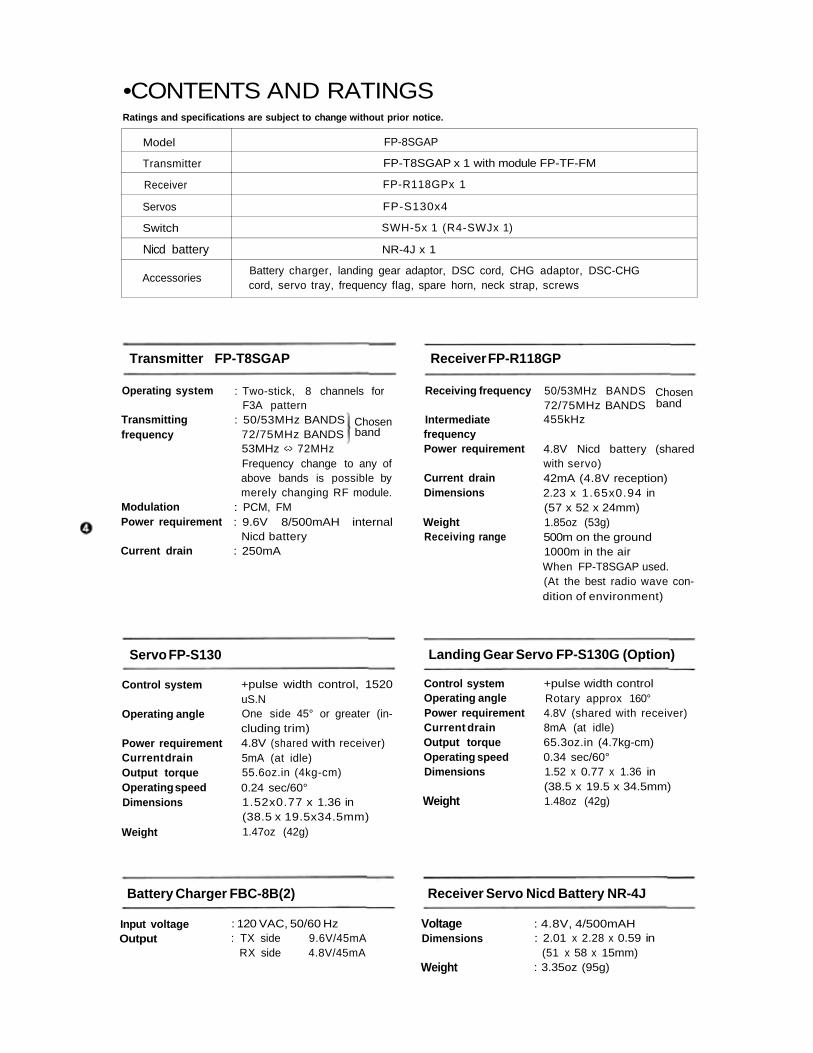
•CONTENTS AND RATINGSRatings and specifications are subject to change without prior notice.
Model
Transmitter
Receiver
Servos
Switch
Nicd battery
Accessories
FP-8SGAP
FP-T8SGAP x 1 with module FP-TF-FM
FP-R118GPx 1
FP-S130x4
SWH-5x 1 (R4-SWJx 1)
NR-4J x 1
Battery charger, landing gear adaptor, DSC cord, CHG adaptor, DSC-CHGcord, servo tray, frequency flag, spare horn, neck strap, screws
Transmitter FP-T8SGAP Receiver FP-R118GP
Operating system
Transmittingfrequency
ModulationPower requirement
Current drain
Chosenband
: Two-stick, 8 channels forF3A pattern
: 50/53MHz BANDS72/75MHz BANDS53MHz <-> 72MHzFrequency change to any ofabove bands is possible bymerely changing RF module.
: PCM, FM: 9.6V 8/500mAH internal
Nicd battery: 250mA
Receiving frequency
IntermediatefrequencyPower requirement
Current drainDimensions
WeightReceiving range
50/53MHz BANDS72/75MHz BANDS455kHz
Chosenband
4.8V Nicd battery (sharedwith servo)42mA (4.8V reception)2.23 x 1.65x0.94 in(57 x 52 x 24mm)1.85oz (53g)500m on the ground1000m in the airWhen FP-T8SGAP used.(At the best radio wave con-dition of environment)
Servo FP-S130 Landing Gear Servo FP-S130G (Option)
Control system
Operating angle
Power requirementCurrent drainOutput torqueOperating speedDimensions
Weight
+pulse width control, 1520uS.NOne side 45° or greater (in-cluding trim)4.8V (shared with receiver)5mA (at idle)55.6oz.in (4kg-cm)0.24 sec/60°1.52x0.77 x 1.36 in(38.5 x 19.5x34.5mm)1.47oz (42g)
Control systemOperating anglePower requirementCurrent drainOutput torqueOperating speedDimensions
Weight
+pulse width controlRotary approx 160°4.8V (shared with receiver)8mA (at idle)65.3oz.in (4.7kg-cm)0.34 sec/60°1.52 x 0.77 x 1.36 in(38.5 x 19.5 x 34.5mm)1.48oz (42g)
Battery Charger FBC-8B(2) Receiver Servo Nicd Battery NR-4J
Input voltageOutput
: 120 VAC, 50/60 Hz: TX side 9.6V/45mA
RX side 4.8V/45mA
VoltageDimensions
Weight
: 4.8V, 4/500mAH: 2.01 x 2.28 x 0.59 in
(51 x 58 x 15mm): 3.35oz (95g)
•GLOSSARY OF TERMSNOTE: Please take the time to familiarize yourself with the terms and abbreviationsbelow. They will be used throughout the instructions and are important in understand-ing the operation and potential of your system.
PCM (Pulse Code Modulation)Pulse Code Modulation utilizes a precise digitalcode to convey information from the transmitterencoder to the receiver. This state of the art meth-od makes many of the sophisticated functions ofthe FP-8SGAP possible, as well as providing farsuperior immunity to noise and interference thanis possible with conventional encoding methods.
ATV (Adjustable Travel Volume)This feature allows independent adjustment ofservo travel in each direction. ATV is sometimesreferred to as "endpoint adjustment". Two dif-ferent types of ATV are standard with this system,(1) Pushbutton or Programmed (Memory) ATVand (2) 2nd ATV (Conventional).
MEMORY ATVThis type is available on all eight channels. Theseadjustments are stored in the transmitter memorycircuit and are retained when the power switch isturned OFF. They are lost however, if the trans-mitter Nicd batteries reach full discharge.
2ND ATVAvailable on Aileron (CH 1) and Elevator (CH 2).This is the conventional type ATV which is set byusing trimmer pots on the transmitter back panel.These settings are NOT affected if the transmitterbatteries are discharged.
DUAL RATERate switches allow the pilot to select differentservo travel limits (for varying control sensitivity)in flight. Servo travel is affected equally in bothdirections from center.
SAFETY (ACT/INHIB) SWITCHESThese switches, located on the transmitter trimmerpanel allow mixing and certain other functions tobe deactivated when not desired. When the SafetySwitches are set to the INHIB position, the func-tion will remain OFF even if the transmitter con-trol switch is set to ON.
VTR (VARIABLE TRACE RATIO)This is a special type of non-linear control re-sponse. When VTR is used, servo travel is normaland linear up to about 80 percent of the transmit-ter control stick movement where the servo travelis abruptly increased to a higher rate (both ratesadjustable). This allows a normal feel for most f ly-ing with extra movement available for emergenciesand certain aerobatic maneuvers. Another way tothink of this function is as "automatic Dual Rate".
SERVO REVERSINGThis function allows the modeler to reverse thedirection of servo movement (in relation to con-trol stick movement) for various installation re-quirements. This can be done by convenientlyflipping a switch on the trimmer panel. Servotravel and neutral position are not affected.
BFS (Battery Fail Safe)This function provides a warning to the flyer whenairborne battery voltage reaches a critically lowlevel by moving the throttle servo to medium slowor slow position.
ATL (Adjustable Throttle Limit)This feature makes adjusting the throttle linkagemuch easier. The throttle trim lever affects onlythe LOW or IDLE position and not the HIGHthrottle servo position. Therefore, the linkage canbe set for proper opening at high throttle and thetrim lever used to set the proper idle speed with-out changing the maximum opening.
MIXINGIn general, mixing functions allow two or moredifferent channels to be operated by moving asingle transmitter control. Many useful and versa-tile functions are made possible in this manner.Three types of mixing functions are provided.(1) Unidirectional mixing — This function allowsone or more channels to be "slaved" to a "master"channel. Movement of the master channel controlcauses movement of both master and slaved servossimultaneously. Operation of the slave channelcontrol however, does not cause movement of themaster channel servo. An example is Aileron/Rud-der mixing (see page 33) where the Rudder isslaved to Ailerons for coordinated turns.(2) Mutual (Bi-Directional) Mixing — With thistype of mixing, two channels are mixed so thatoperation of the control for either channel causesmovement of both servos. This is useful in provid-ing sophisticated functions such as V-tail opera-tion, flaprons, and elevons on tai l less designs.(3) Switch-Activated Mixing — Two or morechannels can be programmed so that the servosinvolved move to a preset position when a trans-mitter control switch is pulled or button pushed.Snap roll switches, roll buttons, and pre-set flapswitches are examples of this type of mixing.
PROGRAMMED MIXING FAIL SAFEUnidirectional mixing of any two channels desiredis possible using the pin board and jumper con-nectors on the transmitter back panel. Either chan-nel may be designated as "master" or "slave"
DSC (Direct Servo Control)Operation of the entire system with the transmit-ter switch in OFF position is possible using theDSC cord. This is useful for checking and adjustingcontrol movements on the ground while someoneelse is flying on your frequency.
The Fail Safe function moves servos to a pre-setposition if the transmitter signal is lost or inter-rupted by strong interferrence. The servos will beheld in the pre-set position until a proper signal isagain received at which time Fail Safe is released.
HOLDThe Hold function holds servos at the same posi-tion as immediately prior to signal interruption.Hold is released when a proper signal is resumed.
•BASIC TRANSMITTER CONTROLSThe servo reversing switches are assumed to be in the normal position in the descrip-tions in this section. When the reversing switches are in the reverse position, servooperation is the opposite of that described here.
Aileron stick Controls the ailerons.
Controls the elevators.
Controls the throttle.
Controls the rudder.
Elevator stick
Throttle stick
Rudder stick
Landing gear switch Controls the landing gear.
Flap and flap trim control (CH6) knob
Spoiler (CH7) control knob
Pitch control (CH8) lever and pitch controlHIGH side trimmer
Idle-up lever
Flap, spoiler -> elevator (6, 7 -> 2) mixing ON-OFF switch
Throttle -> (flap, spoiler) -> elevator (3 -> 6, 7 ->2) mixing / Throttle -> pitch control mixingON-OFF switch
Elevator -> flap (2 -> 6) mixing ON-OFF switch
Snap Roll ON-OFF switch (self off)
Aileron dual rate switch (2-stage)
Elevator dual rate switch
Rudder dual rate/Programmable mixing ON-OFF switch
Aileron trim lever
Elevator trim lever
19 Throttle trim lever with ATL
20 Rudder trim lever
21 Tachometer/timer
The tachometer/timer has the following func-tions:7. TACHOMETER
• Measurement by external sensor.• Two blade propeller specifications:
LOW range 100 to 30,000 rpmError 100 rpm
HIGH range 100 to 60,000 rpmError 200 rpm
2. UP TIMER• 0 to 60 minutes with seconds display.
3. DOWN TIMER• 60 to 0 minutes with seconds display.
4. INTEGRATING TIMER• 0 to 60 hours with minutes display.
5. BATTERY ALARM• Alarm sounds when the transmitter Nicd
batteries approach the usage limit.
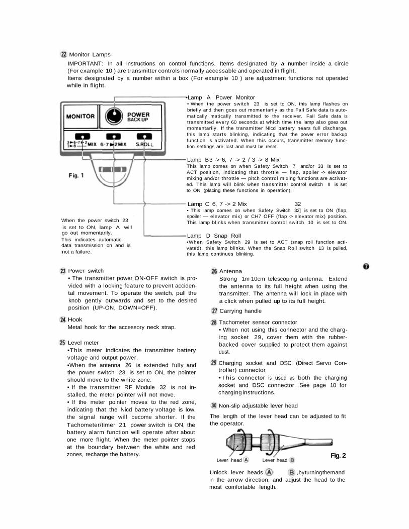
Monitor Lamps
IMPORTANT: In all instructions on control functions. Items designated by a number inside a circle(For example 10 ) are transmitter controls normally accessable and operated in flight.Items designated by a number within a box (For example 10 ) are adjustment functions not operatedwhile in flight.
•Lamp A Power Monitor• When the power switch 23 is set to ON, this lamp flashes onbriefly and then goes out momentarily as the Fail Safe data is auto-matically matically transmitted to the receiver. Fail Safe data istransmitted every 60 seconds at which time the lamp also goes outmomentarily. If the transmitter Nicd battery nears full discharge,this lamp starts blinking, indicating that the power error backupfunction is activated. When this occurs, transmitter memory func-tion settings are lost and must be reset.
Lamp B3 -> 6, 7 -> 2 / 3 -> 8 MixThis lamp comes on when Safety Switch 7 and/or 33 is set toACT position, indicating that throttle — flap, spoiler -> elevatormixing and/or throttle — pitch control mixing functions are activat-ed. This lamp will blink when transmitter control switch II is setto ON (placing these functions in operation).
Lamp C 6, 7 -> 2 Mix 32• This lamp comes on when Safety Switch 32] is set to ON (flap,spoiler — elevator mix) or CH7 OFF (flap -> elevator mix) position.This lamp blinks when transmitter control switch 10 is set to ON.When the power switch 23
is set to ON, lamp A willgo out momentarily.This indicates automaticdata transmission on and isnot a failure.
Lamp D Snap Roll•When Safety Switch 29 is set to ACT (snap roll function acti-vated), this lamp blinks. When the Snap Roll switch 13 is pulled,this lamp continues blinking.
Power switch• The transmitter power ON-OFF switch is pro-vided with a locking feature to prevent acciden-tal movement. To operate the switch, pull theknob gently outwards and set to the desiredposition (UP-ON, DOWN=OFF).
HookMetal hook for the accessory neck strap.
Level meter•This meter indicates the transmitter batteryvoltage and output power.•When the antenna 26 is extended fully andthe power switch 23 is set to ON, the pointershould move to the white zone.• If the transmitter RF Module 32 is not in-stalled, the meter pointer will not move.• If the meter pointer moves to the red zone,indicating that the Nicd battery voltage is low,the signal range will become shorter. If theTachometer/timer 21 power switch is ON, thebattery alarm function will operate after aboutone more flight. When the meter pointer stopsat the boundary between the white and redzones, recharge the battery.
AntennaStrong 1m 10cm telescoping antenna. Extendthe antenna to its full height when using thetransmitter. The antenna will lock in place witha click when pulled up to its full height.
Carrying handle
Tachometer sensor connector• When not using this connector and the charg-ing socket 29, cover them with the rubber-backed cover supplied to protect them againstdust.
Charging socket and DSC (Direct Servo Con-troller) connector•This connector is used as both the chargingsocket and DSC connector. See page 10 forcharging instructions.
Non-slip adjustable lever head
Fig. 2Lever head Lever head
The length of the lever head can be adjusted to fitthe operator.
Unlock lever heads , by turning them andin the arrow direction, and adjust the head to themost comfortable length.
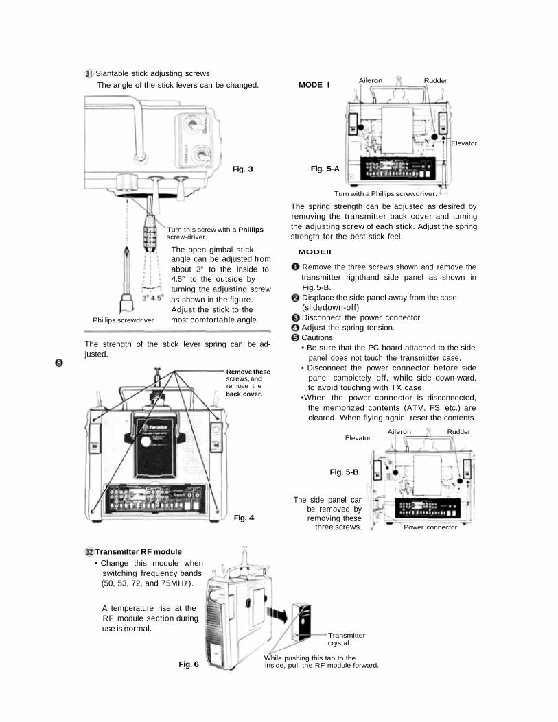
MODE ISlantable stick adjusting screws
The angle of the stick levers can be changed.
Fig. 3
Turn this screw with a Phillipsscrew-driver.
The open gimbal stickangle can be adjusted fromabout 3° to the inside to4.5° to the outside byturning the adjusting screwas shown in the figure.Adjust the stick to themost comfortable angle.Phillips screwdriver
The strength of the stick lever spring can be ad-justed.
Remove thesescrews, andremove theback cover.
Fig. 4
Fig. 5-A
Elevator
RudderAileron
Turn with a Phillips screwdriver.
The spring strength can be adjusted as desired byremoving the transmitter back cover and turningthe adjusting screw of each stick. Adjust the springstrength for the best stick feel.
MODEII
Remove the three screws shown and remove thetransmitter righthand side panel as shown inFig. 5-B.Displace the side panel away from the case.(slide down-off)Disconnect the power connector.Adjust the spring tension.Cautions• Be sure that the PC board attached to the side
panel does not touch the transmitter case.• Disconnect the power connector before side
panel completely off, while side down-ward,to avoid touching with TX case.
•When the power connector is disconnected,the memorized contents (ATV, FS, etc.) arecleared. When flying again, reset the contents.
Elevator
Fig. 5-B
The side panel canbe removed byremoving these
three screws.
Aileron Rudder
Power connector
Transmitter RF module• Change this module when
switching frequency bands(50, 53, 72, and 75MHz).
A temperature rise at theRF module section duringuse is normal.
Fig. 6
Transmittercrystal
While pushing this tab to theinside, pull the RF module forward.
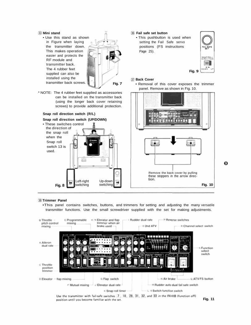
Mini stand• Use this stand as shown
in Figure when layingthe transmitter down.This makes operationeasier and protects theRF module andtransmitter back.The 4 rubber feetsupplied can also beinstalled using thetransmitter back screws.
Fail safe set button• This pushbutton is used when
setting the Fail Safe servopositions (FS instructionsPage 25).
Fig. 9
Back Cover• Removal of this cover exposes the trimmer
panel. Remove as shown in Fig. 10.Fig. 7
* NOTE: The 4 rubber feet supplied as accessoriescan be installed on the transmitter back(using the longer back cover retainingscrews) to provide additional protection.
the snap rollwhen theSnap rollswitch 13 isused.
Fig. 8Up-downswitching
Remove the back cover by pullingthese stoppers in the arrow direc-tion.
Fig. 10Left-rightswitching
Snap roll direction switch (R/L)
Snap roll direction switch (UP/DOWN)• These switches control
the direction of
Trimmer Panel•This panel contains switches, buttons, and trimmers for setting and adjusting the many versatile
transmitter functions. Use the small screwdriver supplied with the set for making adjustments.
Fig. 11
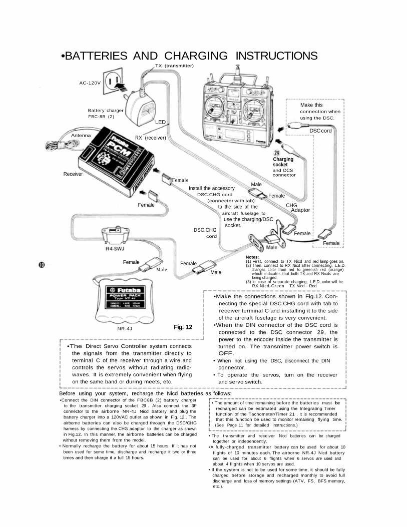
•BATTERIES AND CHARGING INSTRUCTIONS
•The Direct Servo Controller system connectsthe signals from the transmitter directly toterminal C of the receiver through a wire andcontrols the servos without radiating radio-waves. It is extremely convenient when flyingon the same band or during meets, etc.
•Make the connections shown in Fig.12. Con-necting the special DSC.CHG cord with tab toreceiver terminal C and installing it to the sideof the aircraft fuselage is very convenient.
•When the DIN connector of the DSC cord isconnected to the DSC connector 29, thepower to the encoder inside the transmitter isturned on. The transmitter power switch isOFF.
• When not using the DSC, disconnect the DINconnector.
• To operate the servos, turn on the receiverand servo switch.
Before using your system, recharge the Nicd batteries as follows:•Connect the DIN connector of the FBC8B (2) battery charger
to the transmitter charging socket 29 . Also connect the 3Pconnector to the airborne NR-4J Nicd battery and plug thebattery charger into a 120VAC outlet as shown in Fig. 12 . Theairborne batteries can also be charged through the DSC/CHGharness by connecting the CHG adaptor to the charger as shownin Fig.12. In this manner, the airborne batteries can be chargedwithout removing them from the model.
• Normally recharge the battery for about 15 hours. If it has notbeen used for some time, discharge and recharge it two or threetimes and then charge it a full 15 hours.
• The transmitter and receiver Nicd batteries can be chargedtogether or independently.
•A fully-charged transmitter battery can be used for about 10flights of 10 minutes each. The airborne NR-4J Nicd batterycan be used for about 6 flights when 6 servos are used andabout 4 flights when 10 servos are used.
• If the system is not to be used for some time, it should be fullycharged before storage and recharged monthly to avoid fulldischarge and loss of memory settings (ATV, FS, BFS memory,etc.).
TX (transmitter)
AC-120V
Battery charger
FBC-8B (2)LED
Make thisconnection when
using the DSC.
DSC cord
Chargingsocketand DCSconnector
RX (receiver)
Female
Install the accessoryDSC.CHG cord
Male
Antenna
Receiver
(connector with tab)
to the side of theaircraft fuselage to
use the charging/DSCsocket.
DSC.CHGcord
Female
Female
CHGAdaptor
Female
Female
Male
FemaleMale
FemaleNotes:(1) First, connect to TX Nicd and red lamp goes on.(2) Then, connect to RX Nicd after connecting, L.E.D.
changes color from red to greenish red (orange)which indicates that both TX and RX Nicds arebeing charged.
(3) In case of separate charging, L.E.D, color will be:RX Nicd-Green TX Nicd - Red
NR-4J Fig. 12
• The amount of time remaining before the batteries must berecharged can be estimated using the Integrating Timerfunction of the Tachometer/Timer 21 . It is recommendedthat this function be used to monitor remaining flying time.(See Page 11 for detailed instructions.)
•TACHOMETER/TIMER OPERATION
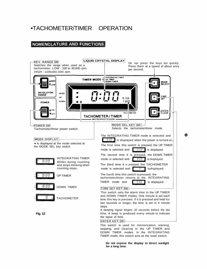
LIQUID CRYSTAL DISPLAYDo not press the keys too quickly.Press them at a speed of about onceper second. |
Do not expose the display to direct sunlightfor a long time.
INTEGRATING TIMERBlinks during countingand stops blinking whencounting stops.
UP TIMER
DOWN TIMER
TACHOMETER
Fig. 13
This switch sets the alarm time in the UP TIMERand DOWN TIMER modes. One minute is set eachtime this key is pressed. If it is pressed and held fortwo seconds or longer, the time is set in 5 minutesteps.A beeping signal begins 10 seconds before the dottime. A beep is produced every minute to indicatethe lapse of time.
This switch is used for memorization, starting,stopping, and clearing in the UP TIMER andDOWN TIMER modes. In the INTEGRATINGTIMER mode, this switch acts as the reset switch.
Switches the range when used as atachometer. LOW - 100 to 30,000 rpm.HIGH -100to60,000 rpm
Tachometer/timer power switch.
is displayed at the mode selected atthe MODE SEL key switch
Selects the tachometer/timer mode.
The INTEGRATING TIMER mode is selected and
is displayed when the power is turned on,
The first time this switch is pressed, the UP TIMER
mode is selected and is displayed.
The second time it is pressed, the DOWN TIMER
mode is selected and is displayed.
The third time it is pressed, the TACHOMETER
mode is selected and is displayed.
The fourth time this switch is pressed, thetachometer/timer returns to the INTEGRATING
is displayed.TIMER mode and
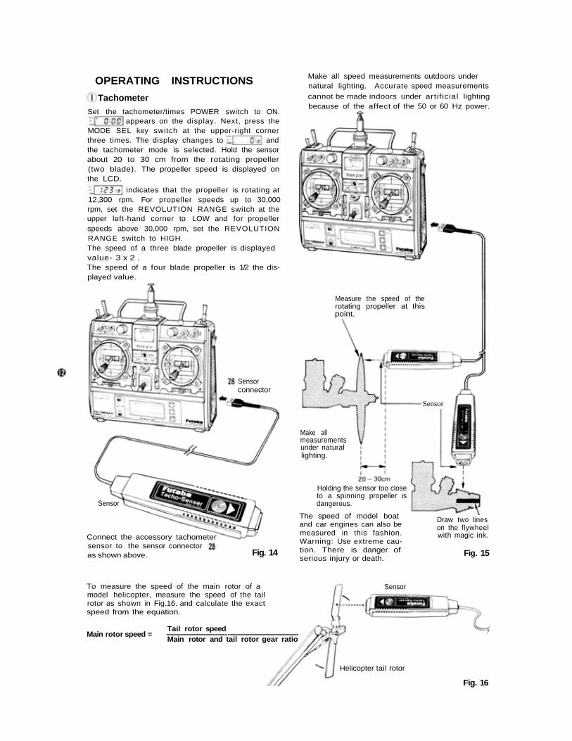
Make all speed measurements outdoors undernatural lighting. Accurate speed measurementscannot be made indoors under artif icial lightingbecause of the affect of the 50 or 60 Hz power.
OPERATING INSTRUCTIONS
TachometerSet the tachometer/times POWER switch to ON.
appears on the display. Next, press theMODE SEL key switch at the upper-right cornerthree times. The display changes to andthe tachometer mode is selected. Hold the sensorabout 20 to 30 cm from the rotating propeller(two blade). The propeller speed is displayed onthe LCD.
indicates that the propeller is rotating at12,300 rpm. For propeller speeds up to 30,000rpm, set the REVOLUTION RANGE switch at theupper left-hand corner to LOW and for propellerspeeds above 30,000 rpm, set the REVOLUTIONRANGE switch to HIGH.The speed of a three blade propeller is displayedvalue- 3 x 2 .The speed of a four blade propeller is 1/2 the dis-played value.
Connect the accessory tachometersensor to the sensor connectoras shown above.
Sensor
Sensorconnector
Fig. 14
The speed of model boatand car engines can also bemeasured in this fashion.Warning: Use extreme cau-tion. There is danger ofserious injury or death.
Measure the speed of therotating propeller at thispoint.
Sensor
Make allmeasurementsunder naturallighting.
Holding the sensor too closeto a spinning propeller isdangerous.
Draw two lineson the flywheelwith magic ink.
Fig. 15
To measure the speed of the main rotor of amodel helicopter, measure the speed of the tailrotor as shown in Fig.16. and calculate the exactspeed from the equation.
Tail rotor speedMain rotor speed = ——————--—--—————————
Main rotor and tail rotor gear ratio
Sensor
Helicopter tail rotor
Fig. 16
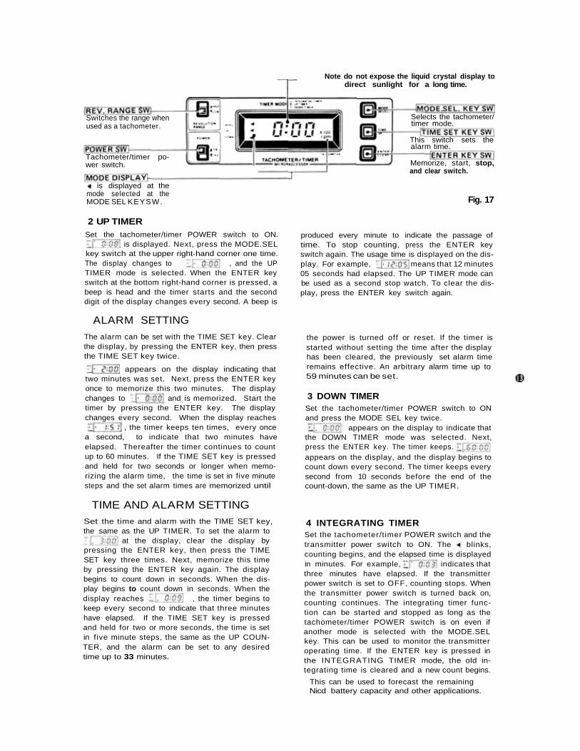
Note do not expose the liquid crystal display todirect sunlight for a long time.
Selects the tachometer/timer mode.
This switch sets thealarm time.
Memorize, start, stop,and clear switch.
Switches the range whenused as a tachometer.
Tachometer/timer po-wer switch.
is displayed at the
Fig. 17mode selected at theMODE SEL KEYSW.
2 UP TIMERSet the tachometer/timer POWER switch to ON.
is displayed. Next, press the MODE.SELkey switch at the upper right-hand corner one time.The display changes to , and the UPTIMER mode is selected. When the ENTER keyswitch at the bottom right-hand corner is pressed, abeep is head and the timer starts and the seconddigit of the display changes every second. A beep is
produced every minute to indicate the passage oftime. To stop counting, press the ENTER keyswitch again. The usage time is displayed on the dis-play. For example, means that 12 minutes05 seconds had elapsed. The UP TIMER mode canbe used as a second stop watch. To clear the dis-play, press the ENTER key switch again.
ALARM SETTING
The alarm can be set with the TIME SET key. Clearthe display, by pressing the ENTER key, then pressthe TIME SET key twice.
appears on the display indicating thattwo minutes was set. Next, press the ENTER keyonce to memorize this two minutes. The displaychanges to and is memorized. Start thetimer by pressing the ENTER key. The displaychanges every second. When the display reaches
, the timer keeps ten times, every once
the power is turned off or reset. If the timer isstarted without setting the time after the displayhas been cleared, the previously set alarm timeremains effective. An arbitrary alarm time up to59 minutes can be set.
3 DOWN TIMERSet the tachometer/timer POWER switch to ONand press the MODE SEL key twice.
appears on the display to indicate thata second, to indicate that two minutes haveelapsed. Thereafter the timer continues to countup to 60 minutes. If the TIME SET key is pressedand held for two seconds or longer when memo-rizing the alarm time, the time is set in five minutesteps and the set alarm times are memorized until
the DOWN TIMER mode was selected. Next,press the ENTER key. The timer keeps.appears on the display, and the display begins tocount down every second. The timer keeps everysecond from 10 seconds before the end of thecount-down, the same as the UP TIMER.
TIME AND ALARM SETTINGSet the time and alarm with the TIME SET key,the same as the UP TIMER. To set the alarm to
at the display, clear the display bypressing the ENTER key, then press the TIMESET key three times. Next, memorize this timeby pressing the ENTER key again. The displaybegins to count down in seconds. When the dis-play begins to count down in seconds. When thedisplay reaches , the timer begins tokeep every second to indicate that three minuteshave elapsed. If the TIME SET key is pressedand held for two or more seconds, the time is setin five minute steps, the same as the UP COUN-TER, and the alarm can be set to any desiredtime up to 33 minutes.
4 INTEGRATING TIMERSet the tachometer/timer POWER switch and thetransmitter power switch to ON. The blinks,counting begins, and the elapsed time is displayedin minutes. For example, indicates thatthree minutes have elapsed. If the transmitterpower switch is set to OFF, counting stops. Whenthe transmitter power switch is turned back on,counting continues. The integrating timer func-tion can be started and stopped as long as thetachometer/timer POWER switch is on even ifanother mode is selected with the MODE.SELkey. This can be used to monitor the transmitteroperating time. If the ENTER key is pressed inthe INTEGRATING TIMER mode, the old in-tegrating time is cleared and a new count begins.
This can be used to forecast the remainingNicd battery capacity and other applications.
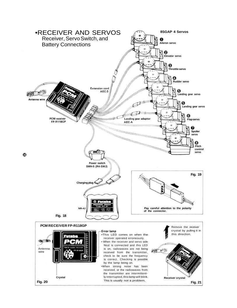
•RECEIVER AND SERVOSReceiver, Servo Switch, andBattery Connections
8SGAP 4 Servos
Aileron servo
Elevator servo
Throttle servo
Rudder servo
Landing gear servo
Landing gear servo
Flap servo
Spoilerservo
Pitchcontrolservo
Power switchSWH-5 (R4-SWJ)
Charging plug
Fig. 19
Pay careful attention to the polarityof the connector.
Fig. 18
NR-4J
PCM RECEIVER FP-R118GP
•This LED comes on when thereceiver operated erroneously.
• When the receiver and servo sideNicd is connected and this LEDis on, radiowaves are not beingreceived from the transmitter,check to be sure the frequencyis correct. Checking is possibleby the lamp being on.
•When strong noise has beenreceived, or the radiowaves fromthe transmitter are intermittent-ly interrupted, this lamp will blink.This is usually not a problem.
Receiver crystal
Fig. 21Fig. 20Crystal
Antennawire
Remove the receivercrystal by pulling it inthis direction.
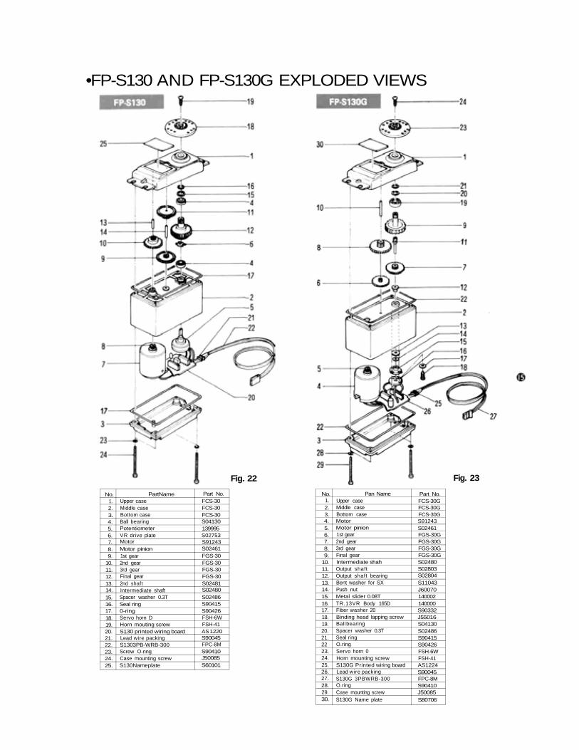
•FP-S130 AND FP-S130G EXPLODED VIEWS
Fig. 22 Fig. 23
No.1.2.3.4.5.6.7.8.9.
10.11.12.13.14.15.16.17.18.19.20.21.22.23.24.25.
PartNameUpper caseMiddle caseBottom caseBall bearingPotentiometerVR drive plateMotorMotor pinion1st gear2nd gear3rd gearFinal gear2nd shaftIntermediate shaftSpacer washer 0.3TSeal ring0-ringServo horn DHorn mouting screwS130 printed wiring boardLead wire packingS1303PB-WRB-300Screw O-nngCase mounting screwS130Nameplate
Part No.FCS-30FCS-30FCS-30S04130139995S02753S91243S02461FGS-30FGS-30FGS-30FGS-30S02481S02480S02486S90415S90426FSH-6WFSH-41AS 1220S90045FPC-8MS90410J50085S60101
No.1.2.3.4.5.6.7.8.9.
10.11.12.13.14.15.16.17.18.19.20.21.2223.24.25.26.27.28.29.30.
Pan NameUpper caseMiddle caseBottom caseMotorMotor pinion1st gear2nd gear3rd gearFinal gearIntermediate shahOutput shaftOutput shaft bearingBent washer for SXPush nutMetal slider 0.08TTR.13VR Body 165DFiber washer 20Binding head lapping screwBall bearingSpacer washer 0.3TSeal ringO.ringServo horn 0Horn mounting screwS130G Printed wiring boardLead wire packingS130G 3PBWRB-300O.ringCase mounting screwS130G Name plate
Part No.FCS-30GFCS-30GFCS-30GS91243S02461FGS-30GFGS-30GFGS-30GFGS-30GS02480S02803S02804S11043J60070140002140000S90332J55016S04130S02486S90415S90426FSH-6WFSH-41AS1224S90045FPC-8MS90410J50085S80706
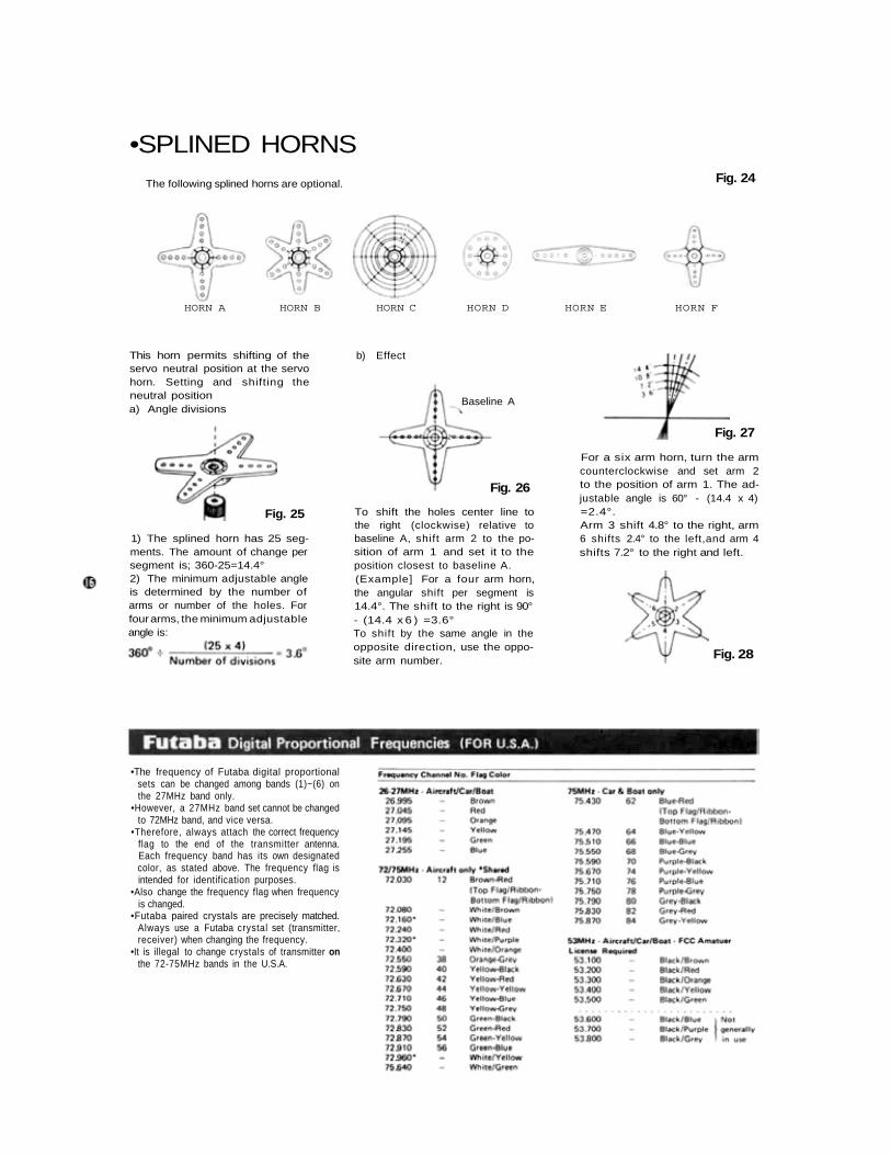
•SPLINED HORNSFig. 24The following splined horns are optional.
HORN A HORN B HORN C HORN D HORN E HORN F
Fig. 25
This horn permits shifting of theservo neutral position at the servohorn. Setting and shifting theneutral positiona) Angle divisions
1) The splined horn has 25 seg-ments. The amount of change persegment is; 360-25=14.4°2) The minimum adjustable angleis determined by the number ofarms or number of the holes. Forfour arms, the minimum adjustableangle is:
b) Effect
Fig. 26
To shift the holes center line tothe right (clockwise) relative tobaseline A, shift arm 2 to the po-sition of arm 1 and set it to theposition closest to baseline A.(Example] For a four arm horn,the angular shift per segment is14.4°. The shift to the right is 90°- (14.4 x 6 ) =3.6°To shift by the same angle in theopposite direction, use the oppo-site arm number.
Fig. 27
For a six arm horn, turn the armcounterclockwise and set arm 2to the position of arm 1. The ad-justable angle is 60° - (14.4 x 4)=2.4°.Arm 3 shift 4.8° to the right, arm6 shifts 2.4° to the left,and arm 4shifts 7.2° to the right and left.
Fig. 28
Baseline A
•The frequency of Futaba digital proportionalsets can be changed among bands (1)~(6) onthe 27MHz band only.
•However, a 27MHz band set cannot be changedto 72MHz band, and vice versa.
•Therefore, always attach the correct frequencyflag to the end of the transmitter antenna.Each frequency band has its own designatedcolor, as stated above. The frequency flag isintended for identification purposes.
•Also change the frequency flag when frequencyis changed.
•Futaba paired crystals are precisely matched.Always use a Futaba crystal set (transmitter,receiver) when changing the frequency.
•It is illegal to change crystals of transmitter onthe 72-75MHz bands in the U.S.A.
•BASIC LINKAGES AND INSTALLATIONThe FP-8SGAP has a servo reversing switch and ATV (Adjustable Travel Volume) foreach channel. Mount the servos without regard to their direction. Select and link servohorns somewhat larger than those specified by the model manufacturer.
• Install the servos securely. Tighten the mountingscrews until the rubber grommets are slightlycompressed. Note: If the screws are too tight,the vibration dampening effect of the grommetswill be lost.
• Use extension cords as needed.• It is suggested that a separate servo be used on
each aileron as this will allow use of the versatilemixing and differential functions built into thetransmitter. Retractable landing gear can beoperated with a single servo to save weight orwith two servos to simplify the mechanical link-age as desired.
• Connect the pushrod to each servo horn, thencheck to see if the direction of travel in relationto stick movement is correct. If the direction oftravel is reversed, use the servo reversing switchesto correct.
• When installing the switch harness, cut a retangu-lar hole slightly larger that the full stroke of theON/OFF switch and install the switch so that itoperates smoothly. It is best to install the switchinside the fuselage and attach a piece of wire tothe switch so that it can be operated from out-side the aircraft. Locate the switch where it willnot be exposed to engine oil, dust, etc.
•Wrap the receiver in soft foam rubber. Water-and dustproof the receiver by placing it in a
plastic bag and tying the mouth of the bag witha rubber band. Do the same with the airbornebattery pack. Caution: The foam rubber shouldbe loosely wrapped and not compressed. Thiswill provide maximum protection from vibra-tion.
• Use the rubber bands wrapped around the re-ceiver to hold the servo and switch leads.
• Even though the receiver antenna may appear tobe too long, do not shorten it or fold it back.
• Be alert for possible electrical noise.This system has noise rejection circuits, howevernoiseless parts are recommended.
•Operate each servo to its full throw and checkfor slop or binding in the linkage. Unreasonableforce applied to the servo horns can damage theservo or horns and will greatly shorten batterylife. Adjust linkages and servo horns so that theservos move smoothly even when the trim leverand stick are operated simultaneously in thesame direction.
• After installation is complete, recheck each part,then perform a range check by collapsing thetransmitter antenna and extending the receiverantenna to its full length. Operate the transmit-ter at a distance of 60 to 90 feet from the receiv-er. The servos should operate normally at thisdistance.
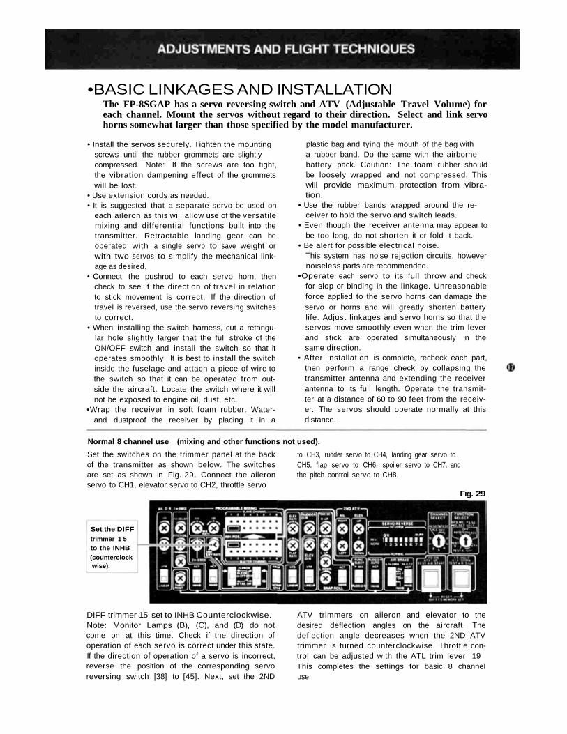
Normal 8 channel use (mixing and other functions not used).
Set the switches on the trimmer panel at the backof the transmitter as shown below. The switchesare set as shown in Fig. 29. Connect the aileronservo to CH1, elevator servo to CH2, throttle servo
to CH3, rudder servo to CH4, landing gear servo toCH5, flap servo to CH6, spoiler servo to CH7, andthe pitch control servo to CH8.
Fig. 29
Set the DIFFtrimmer 1 5to the INHB(counterclockwise).
DIFF trimmer 15 set to INHB Counterclockwise.Note: Monitor Lamps (B), (C), and (D) do notcome on at this time. Check if the direction ofoperation of each servo is correct under this state.If the direction of operation of a servo is incorrect,reverse the position of the corresponding servoreversing switch [38] to [45]. Next, set the 2ND
ATV trimmers on aileron and elevator to thedesired deflection angles on the aircraft. Thedeflection angle decreases when the 2ND ATVtrimmer is turned counterclockwise. Throttle con-trol can be adjusted with the ATL trim lever 19This completes the settings for basic 8 channeluse.
•USING ATV (ADJUSTABLE TRAVEL VOLUME)GENERAL - ATV (Adjustable Travel Volume)allows independent adjustment of servo maximumthrow in each direction (without affecting theneutral position). This is also sometimes referredto as "separate endpoint adjustment". ATV is veryconvenient when for example: a model requiresmore DOWN elevator deflection than UP for equalinside and outside loops (with equal control stick
deflection). Other aircraft may require slightlydifferent RIGHT or LEFT aileron or rudderdeflection to give equal response in each direction(due to engine torque, precision of the model,etc.). Two different ATV functions are possiblewith this system. Memory (Pushbutton) ATV and2ND ATV.
MEMORY (PUSHBUTTON) ATVThis type of ATV is available on all eight channels.Servo travel is adjusted as outlined in the examplebelow.NOTE: Memory ATV settings are retained in thetransmitter memory circuit even when the powerswitch is turned OFF. They are lost however, ifthe transmitter Nicd battery nears full discharge oris removed for servicing.
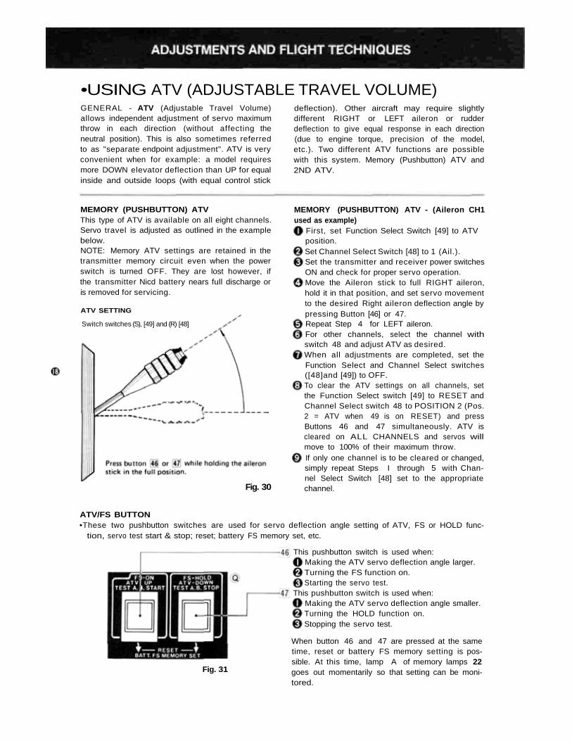
ATV SETTING
Switch switches (S), [49] and (R) [48]
Fig. 30
MEMORY (PUSHBUTTON) ATV - (Aileron CH1used as example)
First, set Function Select Switch [49] to ATVposition.Set Channel Select Switch [48] to 1 (Ail.).Set the transmitter and receiver power switchesON and check for proper servo operation.Move the Aileron stick to full RIGHT aileron,hold it in that position, and set servo movementto the desired Right aileron deflection angle bypressing Button [46] or 47.Repeat Step 4 for LEFT aileron.For other channels, select the channel withswitch 48 and adjust ATV as desired.When all adjustments are completed, set theFunction Select and Channel Select switches([48]and [49]) to OFF.To clear the ATV settings on all channels, setthe Function Select switch [49] to RESET andChannel Select switch 48 to POSITION 2 (Pos.2 = ATV when 49 is on RESET) and pressButtons 46 and 47 simultaneously. ATV iscleared on ALL CHANNELS and servos willmove to 100% of their maximum throw.If only one channel is to be cleared or changed,simply repeat Steps I through 5 with Chan-nel Select Switch [48] set to the appropriatechannel.
ATV/FS BUTTON•These two pushbutton switches are used for servo deflection angle setting of ATV, FS or HOLD func-
tion, servo test start & stop; reset; battery FS memory set, etc.
Fig. 31
This pushbutton switch is used when:Making the ATV servo deflection angle larger.Turning the FS function on.Starting the servo test.
This pushbutton switch is used when:Making the ATV servo deflection angle smaller.Turning the HOLD function on.Stopping the servo test.
When button 46 and 47 are pressed at the sametime, reset or battery FS memory setting is pos-sible. At this time, lamp A of memory lamps 22goes out momentarily so that setting can be moni-tored.
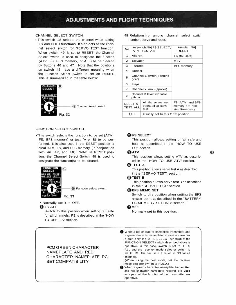
CHANNEL SELECT SWITCH• This switch 48 selects the channel when setting
FS and HOLD functions. It also acts as the chan-nel select switch for SERVO TEST function.When switch 49 is set to RESET, the ChannelSelect switch is used to designate the function(ATV, FS, BFS memory, or ALL) to be clearedby Buttons 46 and 47 . Note that the positionson switch 48 have a different meaning whenthe Function Select Switch is set on RESET.This is summarized in the table below:
Channel select switch
Fig. 32
[48 Relationship among channel select switchnumber, servo and reset.
No.
1.
2.
3.
4.
5.
6.
7.
8.
RESET &TEST ALL
OFF
At switch [49] FS SELECT,ATV, TESTA.B
Aileron
Elevator
Throttle
Rudder
Channel 5 switch (landinggear)
Flaps
Channel 7 knob (spoiler)
Channel 8 lever (variablepitch)
All the servos areoperated at servotest.
Usually set to this OFF position.
At switch [49]RESET
FS (fail safe)
ATV
BFS memory
FS, ATV, and BFSmemory are resetsimultaneously.
FUNCTION SELECT SWITCH
•This switch selects the function to be set (ATV,FS, BFS memory) or test (A or B) to be per-formed. It is also used in the RESET position toclear ATV, FS, and BFS memory (in conjunctionwith 46, 47 , and 4 8 ) . Note: In RESET posi-tion, the Channel Select Switch 48 is used todesignate the function(s) to be cleared.
Function select switch
Fig. 33
• Normally set it to OFF.FS ALLSwitch to this position when setting fail safefor all channels, FS is described in the "HOWTO USE FS" section.
FS SELECTThis position allows setting of fail safe andhold as described in the "HOW TO USEFS" section.ATVThis position allows setting ATV as describ-ed in the "HOW TO USE ATV" section.TEST AThis position allows servo test A as describedin the "SERVO TEST" section.TEST BThis position allows servo test B as describedin the "SERVO TEST" section.BFS MEMO SETSwitch to this position when setting the BFSrelease point as described in the "BATTERYFS MEMORY SETTING" section.OFFNormally set to this position.
PCM GREEN CHARACTERNAMEPLATE AND REDCHARACTER NAMEPLATE RCSET COMPATIBILITY
When a red character nameplate transmitter anda green character nameplate receiver are used asa pair, only the 2 FS SELECT function of theFUNCTION SELECT switch described above isoperative. In this case, switch is set to I FSALL and the receiver mode selector switch Isset to FS. The fail safe function is ON for allchannels.(When using the hold mode, set the receivermode selector switch to HOLD.)When a green character nameplate transmitterand red character nameplate receiver are usedas a pair, all the function of the transmitter areoperative.
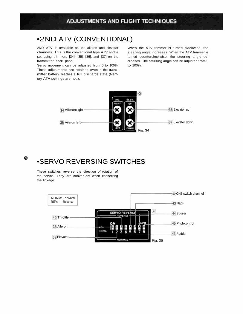
•2ND ATV (CONVENTIONAL)2ND ATV is available on the aileron and elevatorchannels. This is the conventional type ATV and isset using trimmers [34], [35]. [36], and [37] on thetransmitter back panel.Servo movement can be adjusted from 0 to 100%.These adjustments are retained even if the trans-mitter battery reaches a full discharge state (Mem-ory ATV settings are not.).
When the ATV trimmer is turned clockwise, thesteering angle increases. When the ATV trimmer isturned counterclockwise, the steering angle de-creases. The steering angle can be adjusted from 0to 100%.
Aileron right-
Aileron left-
Elevator up
Elevator down
Fig. 34
•SERVO REVERSING SWITCHESThese switches reverse the direction of rotation ofthe servos. They are convenient when connectingthe linkage.
NORM: ForwardREV: Reverse
Throttle
CH5 switch channel
Flaps
Spoiler
Pitch control
Rudder
Aileron
ElevatorFig. 35
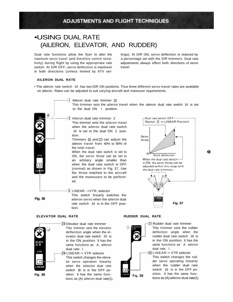
•USING DUAL RATE(AILERON, ELEVATOR, AND RUDDER)
Dual rate functions allow the flyer to alter themaximum servo travel (and therefore control sensi-tivity) during flight by using the appropriate rateswitch. At D/R OFF, servo deflection is maximumin both directions (unless limited by ATV set-
tings). At D/R ON, servo deflection is reduced bya percentage set with the D/R trimmers. Dual rateadjustments always effect both directions of servotravel.
AILERON DUAL RATE
• The aileron rate switch 14 has two D/R ON positions. Thus three different servo travel rates are availableon aileron. Rates can be adjusted to suit varying aircraft and maneuver requirements.
Aileron dual rate trimmer (1)This trimmer sets the aileron travel when the aileron dual rate switch 14 is setto the dual ON I position.
Aileron dual rate trimmer 2This trimmer sets the aileron travelwhen the aileron dual rate switch14 is set to the dual ON 2 posi-
tion.Trimmers [1] and [2] can adjust theaileron travel from 40% to 80% ofthe total travel.When the dual rate switch is set toON, the servo throw can be set toan arbitary angle smaller thanwhen the dual rate switch is OFF(normal) as shown in Fig. 37. Usethe throw matched to the aircraftand the maneuvers to be perform-ed.
LINEAR ->VTR selectorThis switch linearly switches theaileron servo when the aileron dualrate switch 14 is in the OFF posi-tion.
Fig. 37Fig. 36
ELEVATOR DUAL RATE RUDDER DUAL RATE
Fig. 38
Elevator dual rate trimmerThis trimmer sets the elevatordeflection angle when the el-evator dual rate switch 15 isin the ON position. It has thesame functions as A, ailerondual rate I .LINEAR-> VTR selectorThis switch changes the eleva-tor servo operation linearitywhen the selector dual rateswitch 16 is in the OFF po-sition. It has the same func-tions as (A) aileron dual rate(1),
Rudder dual rate trimmerThis trimmer sets the rudderdeflection angle when therudder dual rate switch 16 isin the ON position. It has thesame functions as A ailerondual rate I .LINEAR-> VTR selectorThis switch changes the rud-der servo operating linearitywhen the rudder dual rateswitch 16 is in the OFF po-sition. It has the same func-tions as (A) aileron dual rate(1).
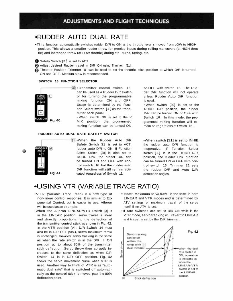
•RUDDER AUTO DUAL RATE•This function automatically switches rudder D/R to ON as the throttle lever is moved from LOW to HIGH
position. This allows a smaller rudder throw for precise inputs during rolling maneuvers (at HIGH throt-tle) and increased throw (at LOW throttle) during stall turns, taxing, etc.
Safety Switch [31]1 is set to ACT.Adjust desired Rudder travel in D/R ON using Trimmer [21].Throttle Position Trimmer 8 can be used to set the throttle stick position at which D/R is turnedON and OFF. Medium slow is recommended.
SWITCH 16 FUNCTION SELECTOR
Fig. 40
•Transmitter control switch 16can be used as a Rudder D/R switchor for turning the programmablemixing function ON and OFF.Usage is determined by the Func-tion Select switch [30] on the trans-mitter back panel.• When switch 30 is set to the PMIX position the programmedmixing function can be turned ON
or OFF with switch 16 . The Rud-der D/R function will not operateunless Rudder Auto D/R functionis used.• When switch [30] is set to theRUDD D/R position, the rudderD/R can be turned ON or OFF withSwitch 16 . In this mode, the pro-grammed mixing function will re-main on regardless of Switch 16 .
RUDDER AUTO DUAL RATE SAFETY SWITCH
Fig. 41
•When the Rudder Auto D/RSafety Switch 31 is set to ACT,rudder auto D/R is ON. If FunctionSelect Switch [30] is also set toRUDD D/R, the rudder D/R canbe turned ON and OFF with con-trol switch 16 but the rudder autoD/R function will stil l remain acti-vated regardless of Switch 16.
•When switch [31] is set to INHIB,the rudder auto D/R function isinoperative. If Function Selectswitch [30] is in the RUDD D/Rposition, the rudder D/R functioncan be turned ON or OFF with con-trol switch 16 . Trimmer 21 setsthe rudder D/R and Auto D/Rdeflection angles.
•USING VTR (VARIABLE TRACE RATIO)•VTR (Variable Trace Ratio) is a new type of
non-linear control response. It is similar to Ex-ponential Control, but is easier to use. Aileronwill be used as an example.
•When the Aileron LINEAR/VTR Switch [3] isin the LINEAR position, servo travel is linearand directly proportional to the deflection ofthe transmitter control stick as shown in Fig. 42.In the VTR position (Ail. D/R Switch 14 mustalso be in D/R OFF pos.), servo maximum throwis unchanged. However servo tracking is the sameas when the rate switch is in the D/R I ONposition up to about 80% of the transmitterstick deflection. Servo throw then abruptly in-creases to the same deflection as when D/RSwitch 14 is in D/R OFF position. Fig. 42shows the servo movement curve when VTR isused. Another way to think of VTR is as "auto-matic dual rate" that is switched off automati-cally as the control stick is moved past the 80%deflection point.
• Note: Maximum servo travel is the same in bothLINEAR and VTR modes and is determined byATV settings or maximum travel of the servoitself if no ATV is set.
• If rate switches are set to D/R ON while in theVTR mode, servo tracking will revert to LINEARand travel is set by the D/R trimmer.
Fig. 42
•When the dualrate switch isON, operationis the same aswhen theLINEAR-VTRswitch is set tothe LINEARposition.
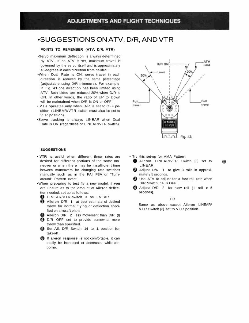
•SUGGESTIONS ON ATV, D/R, AND VTRPOINTS TO REMEMBER (ATV, D/R, VTR)
•Servo maximum deflection is always determinedby ATV. If no ATV is set, maximum travel isgoverned by the servo itself and is approximately45 degrees in each direction from neutral.
•When Dual Rate is ON, servo travel in eachdirection is reduced by the same percentage(adjustable using D/R trimmers). For example,in Fig. 43 one direction has been limited usingATV. Both sides are reduced 20% when D/R isON. In other words, the ratio of UP to Downwill be maintained when D/R is ON or OFF.
• VTR operates only when D/R is set to OFF po-sition (LINEAR/VTR switch must also be set toVTR position).
•Servo tracking is always LINEAR when DualRate is ON (regardless of LINEAR/VTR switch).
Fig. 43
SUGGESTIONS
• VTR is useful when different throw rates aredesired for different portions of the same ma-neuver or when there may be insufficient timebetween maneuvers for changing rate switchesmanually such as in the FAI F3A or "Turn-around" Pattern event.
•When preparing to test fly a new model, if youare unsure as to the amount of Aileron deflec-tion needed, set up as follows.
LINEAR/VTR switch 3. on LINEARAileron D/R I at best estimate of desiredthrow for normal flying or deflection speci-fied on aircraft plans.Aileron D/R 2 less movement than D/R (1)D/R OFF set to provide somewhat morethrow than specified.Set Ail. D/R Switch 14 to 1, position fortakeoff.
If aileron response is not comfortable, it caneasily be increased or decreased while air-borne.
Aileron LINEAR/VTR Switch [3] set toLINEAR.Adjust D/R I to give 3 rolls in approxi-mately 5 seconds.Use ATV to adjust for a fast roll rate whenD/R Switch 14 is OFF.Adjust D/R 2 for slow roll (1 roll in 5seconds).
OR
Same as above except Aileron LINEAR/VTR Switch [3] set to VTR position.
• Try this set-up for AMA Pattern:
•USING ATL (ADJUSTABLE THROTTLE LIMIT)
HIGH
Fig. 44
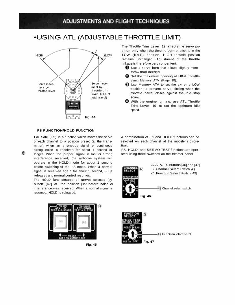
The Throttle Trim Lever 19 affects the servo po-sition only when the throttle control stick is in theLOW (IDLE) position. HIGH throttle positionremains unchanged. Adjustment of the throttlelinkage is therefore very convenient.
Use a servo horn that allows slightly morethrow than needed.Set the maximum opening at HIGH throttleusing Memory ATV (Page 18).Use Memory ATV to set the extreme LOWposition to prevent servo binding when thethrottle barrel closes against the idle stopscrew.With the engine running, use ATL ThrottleTrim Lever 19 to set the optimum idlespeed.
Servo move-ment bythrottle lever
Servo move-ment bythrottle trimlever. (30% oftotal travel)
SLOW
FS FUNCTION/HOLD FUNCTION
Fail Safe (FS) is a function which moves the servoof each channel to a position preset (at the trans-mitter) when an erroneous signal or continuousstrong noise is received for about 1 second orlonger. When the proper signal is lost or stronginterference received, the airborne system willoperate in the HOLD mode for about 1 secondbefore switching to the FS mode. When a normalsignal is received again for about 1 second, FS isreleased and normal control resumes.The HOLD functionstops all servos selected (bybutton [47] at the position just before noise orinterference was received. When a normal signal isresumed, HOLD is released.
A combination of FS and HOLD functions can beselected on each channel at the modeler's discre-tion.FS, HOLD, and SERVO TEST functions are oper-ated using three switches on the trimmer panel.
A. ATV/FS Buttons [46] and [47]B. Channel Select Switch [48|C. Function Select Switch [49]
Channel select switch
Fig. 46
Function select switch
Fig. 45Fig. 47
•FS (FAIL SAFE) AND HOLD FUNCTIONSHOW TO USE FS (FAIL SAFE) (THROTTLE CHANNEL AS AN EXAMPLE.)
Set Function Select Switch 49 to FS SELECT.Set transmitter and receiver power switches toON and check servo movements.While switching the Channel Select Switch 48from 1 to 8 in order, set the channel (s) to beused with FAIL SAFE by pressing Button 46and those to be used with HOLD by pressingButton 47 . (In this example, set CH3 to FSwith Button 46.)Move the throttle lever to maximum slow posi-tion, and press the FS Set Button 36 on thetransmitter back.CH3 is now set to LOW throttle for the FSfunction. After setting FS, turn the ChannelSelect Switch 48 and Function Select Switch49 to OFF.Test FS by turning the transmitter powerswitch to OFF. (In this example, all servosshould move to neutral except the throttleservo which should move to the LOW positionthat was just set.)
Fail Safe for all channels selected can be setwith one touch by moving the sticks andswitches of all the channels to the desired posi-tions and pressing the FS Set Button 36 once.(Switch 49 previously set to FS ALL.)FS settings are retained in the transmittermemory circuit and transmitted automaticallyevery 60 seconds (Monitor Lamp A goes outmomentarily during data transmission.) There-fore, resetting before each flight is unnecessaryeven though the receiver switch has been turnedOFF.After FS settings have been made, always setFunction Select Switch 49 to OFF to preventerroneous settings.To clear all FS settings, set Switch 48 to Posi-tion 1, then press buttons 46 and 47 simul-taneously.
FS/HOLD CAN BE CONFIRMED BY MONITOR LAMP.
• Function status can be confirmed by means of Monitor Lamp A .
When Function Select Switch 49 is at FS SELECT: Lamp A ON = HOLDLamp A; OFF= FS
• When Switch 49 is set to FS ALL, Lamp A is OFF.• When Switch 49 is set to ATV and Button 46 or 47 is pressed. Lamp A, blinks.
•BFS (BATTERY FAIL SAFE) AND BFS MEMORY•BFS (Battery Fail Safe) is a warning function
which moves only the throttle servo to the sameposition as set for FS when there is only a smallamount of power left in the receiver Nicd bat-teries. (If no FS position is set, the throttle servois moved to medium slow.)
•When BFS occurs, the throttle servo can be re-leased and throttle control regained for 36seconds by lowering the throttle lever to IDLE.
• The throttle stick position at which throttle con-trol is regained is programmable. This is knownas BFS Memory and is set as follows:
Set Function Select Switch 49 to BFS MEMOSET and set Channel Select Switch 48 to Pos.3 (Throttle).Set the Throttle stick to the desired releasepoint (between Slow and Medium Slow recom-mended) and press Buttons 46 and 47 simul-taneously. BFS Memory is now set.Set Switches 48 and 49 to OFF.Whenever BFS occurs in flight, lower the throt-tle stick to regain control and immediately landthe aircraft.
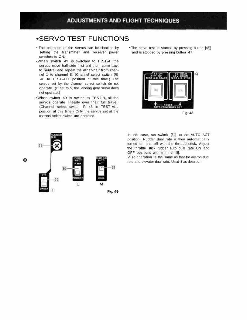
•SERVO TEST FUNCTIONS• The operation of the servos can be checked by
setting the transmitter and receiver powerswitches to ON.
•When switch 49 is switched to TEST-A, theservos move half-side first and then, come backto neutral and repeat the other-half from chan-nel 1 to channel 8. (Channel select switch (R)48 to TEST-ALL position at this time.) The
servos set by the channel select switch do notoperate. (If set to 5, the landing gear servo doesnot operate.)
•When switch 49 is switch to TEST-B, all theservos operate linearly over their full travel.(Channel select switch R 48 in TEST-ALLposition at this time.) Only the servos set at thechannel select switch are operated.
• The servo test is started by pressing button [46]]and is stopped by pressing button 47.
Fig. 48
In this case, set switch [31] to the AUTO ACTposition. Rudder dual rate is then automaticallyturned on and off with the throttle stick. Adjustthe throttle stick rudder auto dual rate ON andOFF positions with trimmer [8].VTR operation is the same as that for aileron dualrate and elevator dual rate. Used it as desired.
Fig. 49
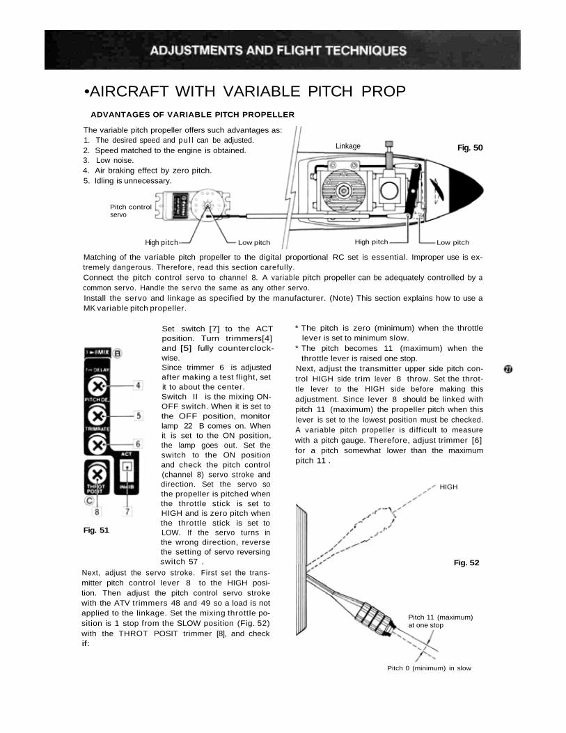
•AIRCRAFT WITH VARIABLE PITCH PROPADVANTAGES OF VARIABLE PITCH PROPELLER
The variable pitch propeller offers such advantages as:1. The desired speed and p u l l can be adjusted.
Fig. 50Linkage2. Speed matched to the engine is obtained.3. Low noise.4. Air braking effect by zero pitch.5. Idling is unnecessary.
Pitch controlservo
High pitch-
Matching of the variable pitch propeller to the digital proportional RC set is essential. Improper use is ex-tremely dangerous. Therefore, read this section carefully.
Low pitch High pitch Low pitch
Connect the pitch control servo to channel 8. A variable pitch propeller can be adequately controlled by acommon servo. Handle the servo the same as any other servo.Install the servo and linkage as specified by the manufacturer. (Note) This section explains how to use aMK variable pitch propeller.
Set switch [7] to the ACTposition. Turn trimmers[4]and [5] fully counterclock-wise.Since trimmer 6 is adjustedafter making a test flight, setit to about the center.Switch II is the mixing ON-OFF switch. When it is set tothe OFF position, monitorlamp 22 B comes on. Whenit is set to the ON position,the lamp goes out. Set theswitch to the ON positionand check the pitch control(channel 8) servo stroke anddirection. Set the servo sothe propeller is pitched whenthe throttle stick is set toHIGH and is zero pitch whenthe throttle stick is set toLOW. If the servo turns inthe wrong direction, reversethe setting of servo reversingswitch 57 .
Fig. 51
Next, adjust the servo stroke. First set the trans-mitter pitch control lever 8 to the HIGH posi-tion. Then adjust the pitch control servo strokewith the ATV trimmers 48 and 49 so a load is notapplied to the linkage. Set the mixing throttle po-sition is 1 stop from the SLOW position (Fig. 52)with the THROT POSIT trimmer [8], and checkif:
* The pitch is zero (minimum) when the throttlelever is set to minimum slow.
* The pitch becomes 11 (maximum) when thethrottle lever is raised one stop.
Next, adjust the transmitter upper side pitch con-trol HIGH side trim lever 8 throw. Set the throt-tle lever to the HIGH side before making thisadjustment. Since lever 8 should be linked withpitch 11 (maximum) the propeller pitch when thislever is set to the lowest position must be checked.A variable pitch propeller is difficult to measurewith a pitch gauge. Therefore, adjust trimmer [6]for a pitch somewhat lower than the maximumpitch 11 .
Pitch 11 (maximum)at one stop
HIGH
Fig. 52
Pitch 0 (minimum) in slow
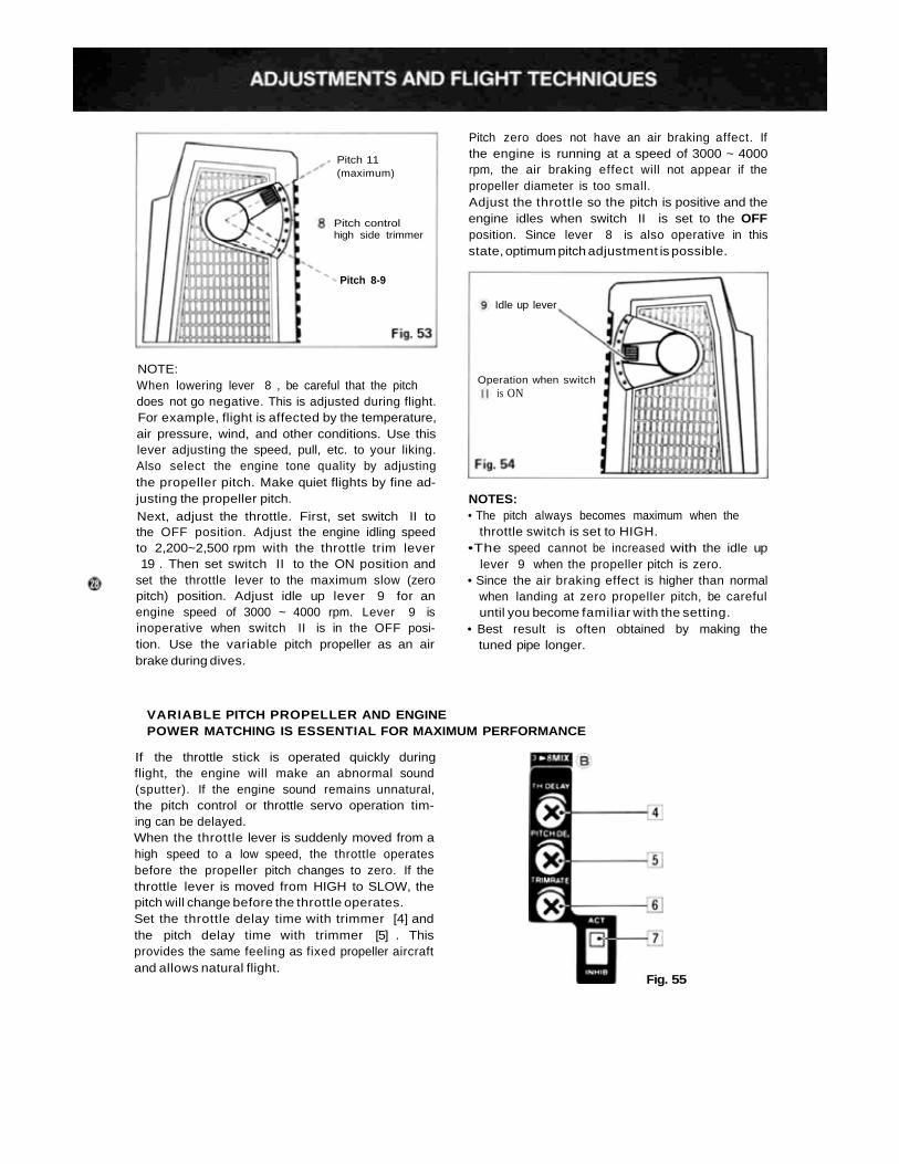
NOTE:When lowering lever 8 , be careful that the pitchdoes not go negative. This is adjusted during flight.For example, flight is affected by the temperature,air pressure, wind, and other conditions. Use thislever adjusting the speed, pull, etc. to your liking.Also select the engine tone quality by adjustingthe propeller pitch. Make quiet flights by fine ad-justing the propeller pitch.Next, adjust the throttle. First, set switch II tothe OFF position. Adjust the engine idling speedto 2,200~2,500 rpm with the throttle trim lever19 . Then set switch II to the ON position and
set the throttle lever to the maximum slow (zeropitch) position. Adjust idle up lever 9 for anengine speed of 3000 ~ 4000 rpm. Lever 9 isinoperative when switch II is in the OFF posi-tion. Use the variable pitch propeller as an airbrake during dives.
Pitch zero does not have an air braking affect. Ifthe engine is running at a speed of 3000 ~ 4000rpm, the air braking effect will not appear if thepropeller diameter is too small.Adjust the throttle so the pitch is positive and theengine idles when switch II is set to the OFFposition. Since lever 8 is also operative in thisstate, optimum pitch adjustment is possible.
Idle up lever
Operation when switchis ON
NOTES:• The pitch always becomes maximum when the
throttle switch is set to HIGH.•The speed cannot be increased with the idle up
lever 9 when the propeller pitch is zero.• Since the air braking effect is higher than normal
when landing at zero propeller pitch, be carefuluntil you become familiar with the setting.
• Best result is often obtained by making thetuned pipe longer.
Pitch 8-9
Pitch controlhigh side trimmer
Pitch 11(maximum)
VARIABLE PITCH PROPELLER AND ENGINEPOWER MATCHING IS ESSENTIAL FOR MAXIMUM PERFORMANCE
If the throttle stick is operated quickly duringflight, the engine will make an abnormal sound(sputter). If the engine sound remains unnatural,the pitch control or throttle servo operation tim-ing can be delayed.When the throttle lever is suddenly moved from ahigh speed to a low speed, the throttle operatesbefore the propeller pitch changes to zero. If thethrottle lever is moved from HIGH to SLOW, thepitch will change before the throttle operates.Set the throttle delay time with trimmer [4] andthe pitch delay time with trimmer [5] . Thisprovides the same feeling as fixed propeller aircraftand allows natural flight.
Fig. 55
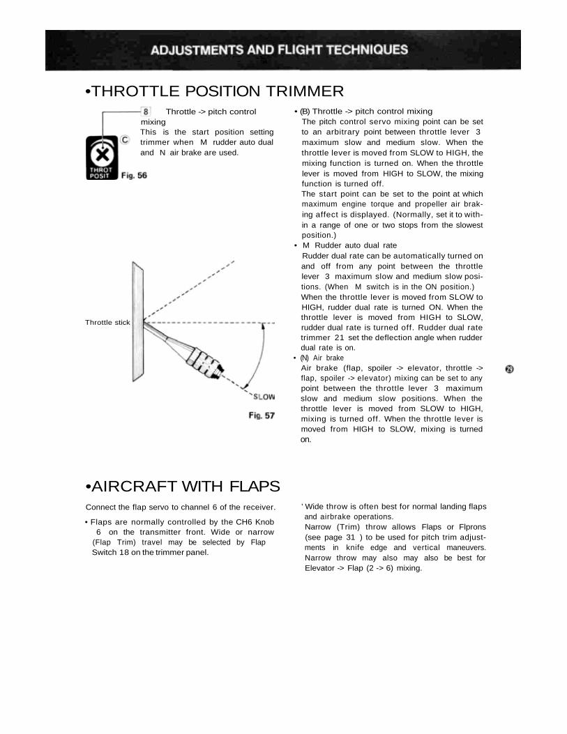
•THROTTLE POSITION TRIMMER
Throttle stick
• (B) Throttle -> pitch control mixingThe pitch control servo mixing point can be setto an arbitrary point between throttle lever 3maximum slow and medium slow. When thethrottle lever is moved from SLOW to HIGH, themixing function is turned on. When the throttlelever is moved from HIGH to SLOW, the mixingfunction is turned off.The start point can be set to the point at whichmaximum engine torque and propeller air brak-ing affect is displayed. (Normally, set it to with-in a range of one or two stops from the slowestposition.)
• M Rudder auto dual rateRudder dual rate can be automatically turned onand off from any point between the throttlelever 3 maximum slow and medium slow posi-tions. (When M switch is in the ON position.)When the throttle lever is moved from SLOW toHIGH, rudder dual rate is turned ON. When thethrottle lever is moved from HIGH to SLOW,rudder dual rate is turned off. Rudder dual ratetrimmer 21 set the deflection angle when rudderdual rate is on.
• (N) Air brakeAir brake (flap, spoiler -> elevator, throttle ->flap, spoiler -> elevator) mixing can be set to anypoint between the throttle lever 3 maximumslow and medium slow positions. When thethrottle lever is moved from SLOW to HIGH,mixing is turned off. When the throttle lever ismoved from HIGH to SLOW, mixing is turnedon.
Throttle -> pitch controlmixingThis is the start position settingtrimmer when M rudder auto dualand N air brake are used.
•AIRCRAFT WITH FLAPSConnect the flap servo to channel 6 of the receiver.
• Flaps are normally controlled by the CH6 Knob6 on the transmitter front. Wide or narrow
(Flap Trim) travel may be selected by FlapSwitch 18 on the trimmer panel.
' Wide throw is often best for normal landing flapsand airbrake operations.Narrow (Trim) throw allows Flaps or Flprons(see page 31 ) to be used for pitch trim adjust-ments in knife edge and vertical maneuvers.Narrow throw may also may also be best forElevator -> Flap (2 -> 6) mixing.
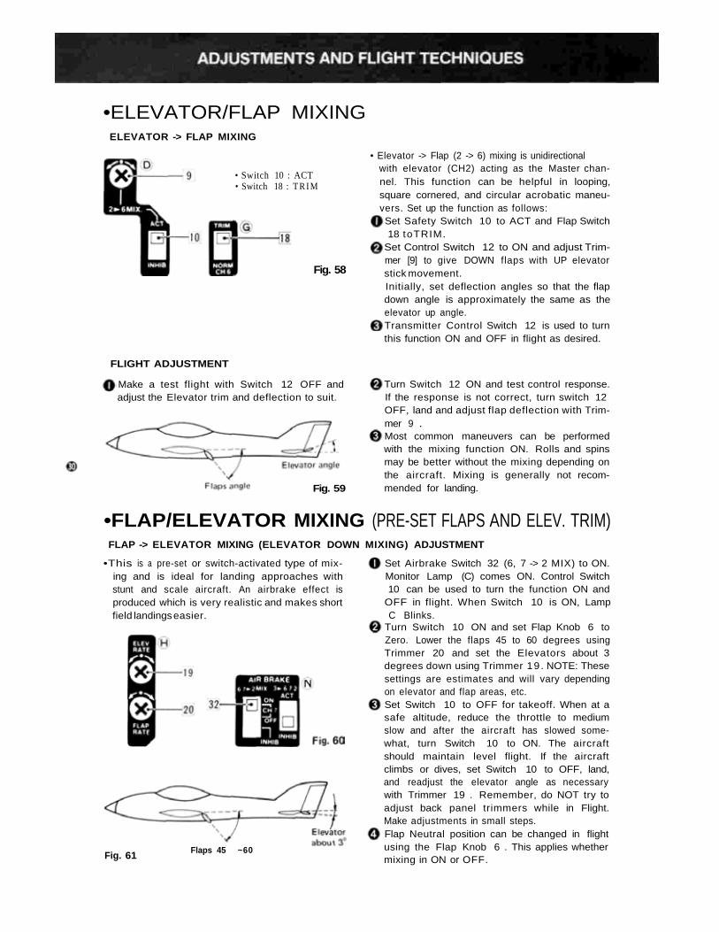
•ELEVATOR/FLAP MIXINGELEVATOR -> FLAP MIXING
• Switch 10 : ACT• Switch 18 : T R I M
• Elevator -> Flap (2 -> 6) mixing is unidirectionalwith elevator (CH2) acting as the Master chan-nel. This function can be helpful in looping,square cornered, and circular acrobatic maneu-vers. Set up the function as follows:Set Safety Switch 10 to ACT and Flap Switch18 toTRIM.
Set Control Switch 12 to ON and adjust Trim-mer [9] to give DOWN flaps with UP elevatorstick movement.Fig. 58
Initially, set deflection angles so that the flapdown angle is approximately the same as theelevator up angle.Transmitter Control Switch 12 is used to turnthis function ON and OFF in flight as desired.
FLIGHT ADJUSTMENT
Make a test flight with Switch 12 OFF andadjust the Elevator trim and deflection to suit.
Turn Switch 12 ON and test control response.If the response is not correct, turn switch 12OFF, land and adjust flap deflection with Trim-mer 9 .Most common maneuvers can be performedwith the mixing function ON. Rolls and spinsmay be better without the mixing depending onthe aircraft. Mixing is generally not recom-mended for landing.Fig. 59
•FLAP/ELEVATOR MIXING (PRE-SET FLAPS AND ELEV. TRIM)FLAP -> ELEVATOR MIXING (ELEVATOR DOWN MIXING) ADJUSTMENT
•This is a pre-set or switch-activated type of mix-ing and is ideal for landing approaches withstunt and scale aircraft. An airbrake effect isproduced which is very realistic and makes shortfield landings easier.
Flaps 45 ~60Fig. 61
Set Airbrake Switch 32 (6, 7 -> 2 MIX) to ON.Monitor Lamp (C) comes ON. Control Switch10 can be used to turn the function ON and
OFF in flight. When Switch 10 is ON, LampC Blinks.
Turn Switch 10 ON and set Flap Knob 6 toZero. Lower the flaps 45 to 60 degrees usingTrimmer 20 and set the Elevators about 3degrees down using Trimmer 19 . NOTE: Thesesettings are estimates and will vary dependingon elevator and flap areas, etc.Set Switch 10 to OFF for takeoff. When at asafe altitude, reduce the throttle to mediumslow and after the aircraft has slowed some-what, turn Switch 10 to ON. The aircraftshould maintain level flight. If the aircraftclimbs or dives, set Switch 10 to OFF, land,and readjust the elevator angle as necessarywith Trimmer 19 . Remember, do NOT try toadjust back panel trimmers while in Flight.Make adjustments in small steps.Flap Neutral position can be changed in flightusing the Flap Knob 6 . This applies whethermixing in ON or OFF.
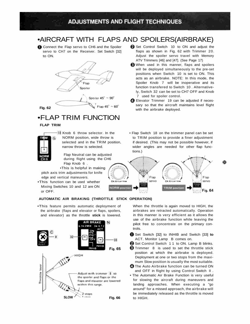
•AIRCRAFT WITH FLAPS AND SPOILERS(AIRBRAKE)Connect the Flap servo to CH6 and the Spoilerservo to CH7 on the Receiver. Set Switch [32]to ON.
Fig. 62
Set Control Switch 10 to ON and adjust theflaps as shown in Fig. 62 with Trimmer 20.Adjust the spoiler servo travel with MemoryATV Trimmers [46] and [47]. (See Page 17)When used in this manner, flaps and spoilerswill be deployed simultaneously to the pre-setpositions when Switch 10 is set to ON. Thisacts as an airbrake. NOTE: In this mode, theSpoiler Knob 7 will be inoperative and itsfunction transfered to Switch 10 . Alternative-ly, Switch 32 can be set to CH7 OFF and Knob7 used for spoiler control.Elevator Trimmer 19 can be adjusted if neces-sary so that the aircraft maintains level flightwith the airbrake deployed.
•FLAP TRIM FUNCTIONFLAP TRIM
• Flap Switch 18 on the trimmer panel can be setto TRIM position to provide a finer adjustmentif desired. (This may not be possible however, ifwider angles are needed for other flap func-tions.)
Knob 6 throw selector. In theNORM position, wide throw isselected and in the TRIM position,narrow throw is selected.
Flap Neutral can be adjustedduring flight using the CH6Flap Knob 6 .
•This is helpful in makingpitch axis trim adjustments for knifeedge and vertical maneuvers.
•This function can be used whetherMixing Switches 10 and 12 are ONor OFF.
AUTOMATIC AIR BRAKING (THROTTLE STICK OPERATION)
•This feature permits automatic deployment ofthe airbrake (flaps and elevator or flaps, spoilers,and elevator) as the throttle stick is lowered.
SLOW Fig. 66
When the throttle is again moved to HIGH, theairbrakes are retracted automatically. Operationin this manner is very efficient as it allows theuse of the airbrake function while leaving thepilot free to concentrate on the primary con-trols.
Set Switch [32] to INHIB and Switch [33] toACT. Monitor Lamp B comes on.Set Control Switch 1 1 to ON. Lamp B blinks.Trimmer 8 is used to set the throttle stickposition at which the airbrake is deployed.Deployment at one or two stops from the maxi-mum Slow position is usually the most suitable.The Auto Airbrake function can be turned ONand OFF in flight by using Control Switch II .
• The Automatic Air Brake Function is very usefulfor slowing the aircraft during maneuvers andlanding approaches. When executing a "goaround" for a missed approach, the airbrake willbe immediately released as the throttle is movedto HIGH.
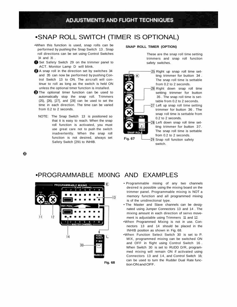
•SNAP ROLL SWITCH (TIMER IS OPTIONAL)•When this function is used, snap rolls can be
performed by pushing the Snap Switch 13 . Snaproll directions can be set using Control Switches34 and 35 .Set Safety Switch 29 on the trimmer panel toACT. Monitor Lamp D will blink.A snap roll in the direction set by switches 34and 35 can now be performed by pushing Con-trol Switch 13 to ON. The aircraft will con-tinue to roll as long as the switch is held ONunless the optional timer function is installed.The optional timer function can be used toautomatically stop the snap roll. Trimmers(25), [26), [27], and [28] can be used to set thetime in each direction. The time can be variedfrom 0.2 to 2 seconds.
NOTE: The Snap Switch 13 is positioned sothat it is easy to reach. When the snaproll function is activated, you mustuse great care not to push the switchinadvertently. When the snap rollfunction is not desired, always setSafety Switch [291 to INHIB.
SNAP ROLL TIMER (OPTION)
These are the snap roll time settingtrimmers and snap roll functionsafety switches.
Right up snap roll time set-ting trimmer for button 34 .The snap roll time is settablefrom 0.2 to 2 seconds.Right down snap roll timesetting trimmer for button35 . The snap roll time is set-
table from 0.2 to 2 seconds.Left up snap roll time settingtrimmer for button 36 . Thesnap roll time is settable from0.2 to 2 seconds.Left down snap roll time set-ting trimmer for button 37.The snap roll time is settablefrom 0.2 to 2 seconds.Snap roll function safetyswitch.
•PROGRAMMABLE MIXING AND EXAMPLES
Fig. 68
• Programmable mixing of any two channelsdesired is possible using the mixing board on thetrimmer panel. Programmable mixing is NOT amemory function and all programmed mixingis of the unidirectional type.
• The Master and Slave channels can be desig-nated using Jumper Connectors 13 and 14 . Themixing amount in each direction of servo move-ment is adjustable using Trimmers 11 and 12.
•When Programmed Mixing is not in use. Con-nectors 13 and 14 should be placed in theINHIB position as shown in Fig. 68.
•When Function Select Switch 30 is set to P.MIX, programmed mixing can be switched ONand OFF in flight using Control Switch 16 .When Switch 30 is set to RUDD D/R, program-med mixing will remain ON if activated usingConnectors 13 and 14, and Control Switch 16;can be used to turn the Rudder Dual Rate func-tion ON and OFF.
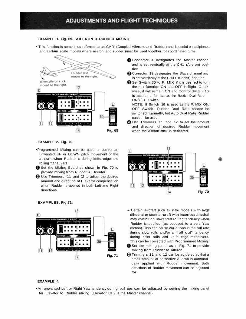
EXAMPLE 1. Fig. 69. AILERON -> RUDDER MIXING
• This function is sometimes referred to as"CAR" (Coupled Ailerons and Rudder) and is useful on sailplanesand certain scale models where aileron and rudder must be used together for coordinated turns.
Connector 4 designates the Master channeland is set vertically at the CH1 (Aileron) posi-tion.Connector 13 designates the Slave channel andis set vertically at the CH4 (Rudder) position.Set Switch 30 to P. MIX if it is desired to turnthe mix function ON and OFF in flight. Other-wise, it will remain ON and Control Switch 16is available for use as the Rudder Dual RateON/OFF Switch.NOTE: If Switch 16 is used as the P. MIX ON/OFF Switch, Rudder Dual Rate cannot beswitched manually, but Auto Dual Rate Ruddercan still be used.Use Trimmers 11 and 12 to set the amountand direction of desired Rudder movementwhen the Aileron stick is deflected.Fig. 69
EXAMPLE 2. Fig. 70.
•Programmed Mixing can be used to correct anunwanted UP or DOWN pitch movement of theaircraft when Rudder is during knife edge androlling maneuvers.Set the Mixing Board as shown in Fig. 70 toprovide mixing from Rudder -> Elevator.Use Trimmers 11 and 12 to adjust the desiredamount and direction of Elevator compensationwhen Rudder is applied in both Left and Rightdirections.
EXAMPLES. Fig.71.
Fig. 70
• Certain aircraft such as scale models with largedihedral or stunt aircraft with incorrect dihedralmay exhibit an unwanted rolling tendency whenRudder is applied (as opposed to a pure Yawmotion). This can cause variations in the roll rateduring slow rolls and/or a "roll out" tendencyduring point rolls and knife edge maneuvers.This can be corrected with Programmed Mixing.Set the mixing panel as in Fig. 71 to providemixing from Rudder to Aileron.Trimmers 11 and 12 can be adjusted so that asmall amount of corrective Aileron is automati-cally applied with Rudder movement. Bothdirections of Rudder movement can be adjustedfor.
Fig. 71
EXAMPLE 4.
•An unwanted Left or Right Yaw tendency during pull ups can be adjusted by setting the mixing panelfor Elevator to Rudder mixing (Elevator CH2 is the Master channel).
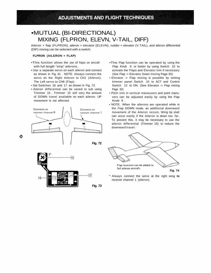
•MUTUAL (BI-DIRECTIONAL)MIXING (FLPRON, ELEVN, V-TAIL, DIFF)
Aileron + flap (FLPRON), aileron + elevator (ELEVN), rudder + elevator (V.TAIL), and aileron differential(DIF) mixing can be selected with a switch.
FLPRON (AILERON + FLAP)
•This function allows the use of flaps on aircraftwith full length "strip" ailerons.
• Use a separate servo on each aileron and connectas shown in Fig. 61 . NOTE: Always connect theservo on the Right Aileron to CH1 (Aileron).The Left servo to CH6 (Flap).
• Set Switches 16 and 17 as shown in Fig. 72.• Aileron differential can be varied to suit using
Trimmer 15 . Trimmer 15 will vary the amountof DOWN travel available on each aileron. UPmovement is not affected.
•The Flap function can be operated by using theFlap Knob 6 or better by using Switch 10 toactivate the Flaps and Elevator trim if necessary(See Flap -> Elevator Down mixing Page 30).
• Elevator -> Flap mixing is possible by settingtrimmer panel Switch 10 to ACT and ControlSwitch 12 to ON. (See Elevator -> Flap mixingPage 30)
• Pitch trim in vertical maneuvers and point manu-vers can be adjusted easily by using the FlapKnob 6 .
• NOTE: When the ailerons are operated while inthe Flap DOWN mode, an additional downwardmovement of the Aileron occurs. Wing tip stallcan occur easily if the Aileron is down too far.To prevent this, it may be necessary to use theaileron differential (Trimmer 15) to reduce thedownward travel.
* Always connect the servo at the right wing toreceiver channel 1 (aileron).
Fig. 73
Fig. 72
Fig. 74
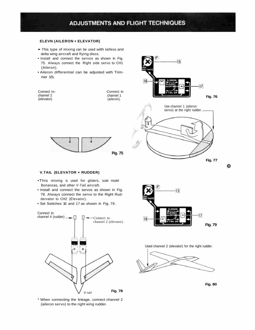
ELEVN (AILERON + ELEVATOR)
• This type of mixing can be used with tailless anddelta wing aircraft and flying discs.
• Install and connect the servos as shown in Fig.75. Always connect the Right side servo to CH1(Aileron).
• Aileron differential can be adjusted with Trim-mer 15.
Connect to-channel 2(elevator).
-Connect tochannel 1(aileron).
Pig. 75
Use channel 1 (aileronservo) at the right rudder.
Fig. 76
Fig. 77
V.TAIL (ELEVATOR + RUDDER)
•This mixing is used for gliders, scale modelBonanzas, and other V-Tail aircraft.
• Install and connect the servos as shown in Fig.78. Always connect the servo to the Right Rud-dervator to CH2 (Elevator).
• Set Switches 16 and 17 as shown in Fig. 79.
Connect tochannel 4 (rudder) Connect to
channel 2 (elevator).Fig. 79
Used channel 2 (elevator) for the right rudder.
Fig. 80
Fig. 78
* When connecting the linkage, connect channel 2(aileron servo) to the right wing rudder.