Embed Size (px)
Citation preview
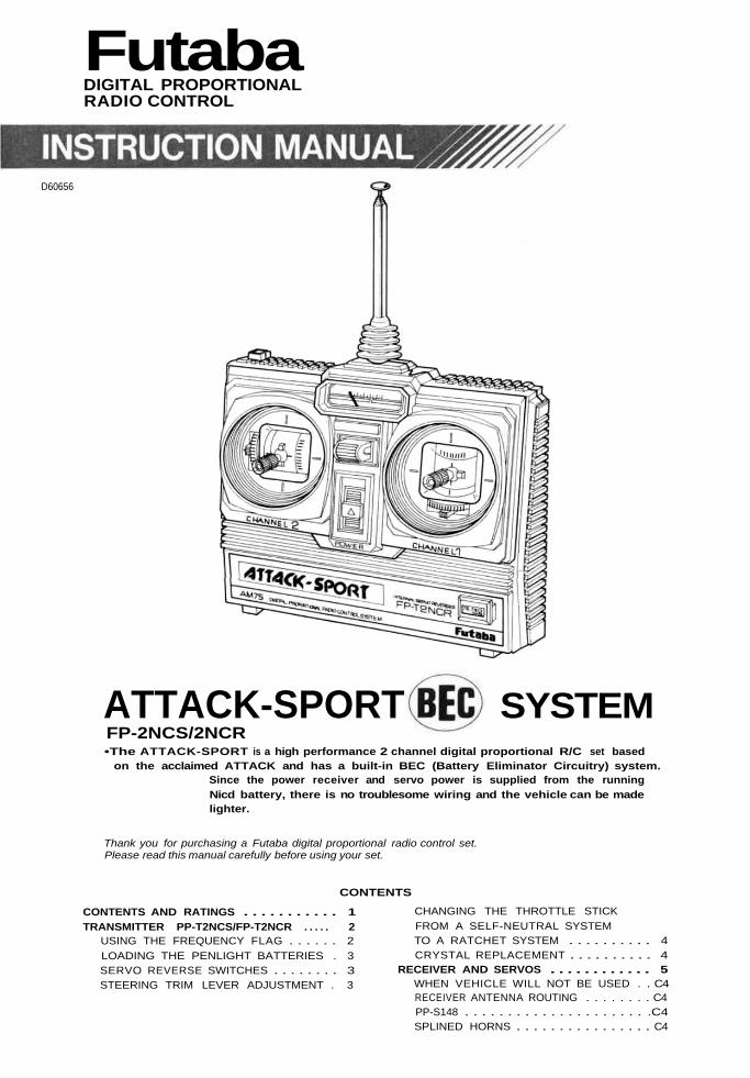
FutabaDIGITAL PROPORTIONALRADIO CONTROL
D60656
ATTACK-SPORT SYSTEMFP-2NCS/2NCR•The ATTACK-SPORT is a high performance 2 channel digital proportional R/C set based
on the acclaimed ATTACK and has a built-in BEC (Battery Eliminator Circuitry) system.Since the power receiver and servo power is supplied from the runningNicd battery, there is no troublesome wiring and the vehicle can be madelighter.
Thank you for purchasing a Futaba digital proportional radio control set.Please read this manual carefully before using your set.
CONTENTS
CONTENTS AND RATINGS . . . . . . . . . . . 1TRANSMITTER PP-T2NCS/FP-T2NCR . . . . . 2
USING THE FREQUENCY FLAG . . . . . . 2LOADING THE PENLIGHT BATTERIES . 3SERVO REVERSE SWITCHES . . . . . . . . 3STEERING TRIM LEVER ADJUSTMENT . 3
CHANGING THE THROTTLE STICKFROM A SELF-NEUTRAL SYSTEMTO A RATCHET SYSTEM . . . . . . . . . . 4CRYSTAL REPLACEMENT . . . . . . . . . . 4
RECEIVER AND SERVOS . . . . . . . . . . . . 5WHEN VEHICLE WILL NOT BE USED . . C4RECEIVER ANTENNA ROUTING . . . . . . . . C4PP-S148 . . . . . . . . . . . . . . . . . . . . . .C4SPLINED HORNS . . . . . . . . . . . . . . . . C4
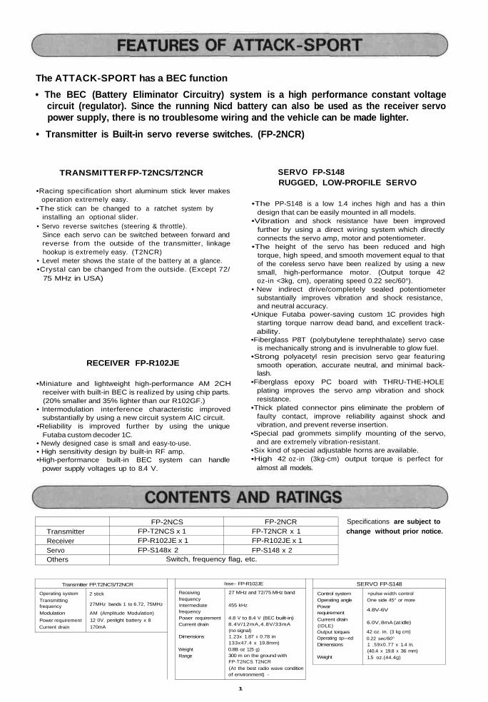
The ATTACK-SPORT has a BEC function• The BEC (Battery Eliminator Circuitry) system is a high performance constant voltage
circuit (regulator). Since the running Nicd battery can also be used as the receiver servopower supply, there is no troublesome wiring and the vehicle can be made lighter.
• Transmitter is Built-in servo reverse switches. (FP-2NCR)
TRANSMITTER FP-T2NCS/T2NCR SERVO FP-S148RUGGED, LOW-PROFILE SERVO
•Racing specification short aluminum stick lever makesoperation extremely easy.
•The stick can be changed to a ratchet system byinstalling an optional slider.
• Servo reverse switches (steering & throttle).Since each servo can be switched between forward andreverse from the outside of the transmitter, linkagehookup is extremely easy. (T2NCR)
• Level meter shows the state of the battery at a glance.•Crystal can be changed from the outside. (Except 72/
75 MHz in USA)
RECEIVER FP-R102JE
•Miniature and lightweight high-performance AM 2CHreceiver with built-in BEC is realized by using chip parts.(20% smaller and 35% lighter than our R102GF.)
• Intermodulation interference characteristic improvedsubstantially by using a new circuit system AIC circuit.
•Reliability is improved further by using the uniqueFutaba custom decoder 1C.
• Newly designed case is small and easy-to-use.• High sensitivity design by built-in RF amp.•High-performance built-in BEC system can handle
power supply voltages up to 8.4 V.
•The PP-S148 is a low 1.4 inches high and has a thindesign that can be easily mounted in all models.
•Vibration and shock resistance have been improvedfurther by using a direct wiring system which directlyconnects the servo amp, motor and potentiometer.
•The height of the servo has been reduced and hightorque, high speed, and smooth movement equal to thatof the coreless servo have been realized by using a newsmall, high-performance motor. (Output torque 42oz-in <3kg, cm), operating speed 0.22 sec/60°).
• New indirect drive/completely sealed potentiometersubstantially improves vibration and shock resistance,and neutral accuracy.
•Unique Futaba power-saving custom 1C provides highstarting torque narrow dead band, and excellent track-ability.
•Fiberglass P8T (polybutylene terephthalate) servo caseis mechanically strong and is invulnerable to glow fuel.
•Strong polyacetyl resin precision servo gear featuringsmooth operation, accurate neutral, and minimal back-lash.
•Fiberglass epoxy PC board with THRU-THE-HOLEplating improves the servo amp vibration and shockresistance.
•Thick plated connector pins eliminate the problem offaulty contact, improve reliability against shock andvibration, and prevent reverse insertion.
•Special pad grommets simplify mounting of the servo,and are extremely vibration-resistant.
•Six kind of special adjustable horns are available.•High 42 oz-in (3kg-cm) output torque is perfect for
almost all models.
TransmitterReceiverServoOthers
FP-2NCSFP-T2NCS x 1FP-R102JE x 1FP-S148x 2
Switch, frequency flag, etc.
FP-2NCRFP-T2NCR x 1FP-R102JE x 1FP-S148 x 2
Specifications are subject tochange without prior notice.
Transmitter FP.T2NCS/T2NCR
Operating systemTransmittingfrequencyModulationPower requirementCurrent drain
2 stick
27MHz bands 1 to 6.72, 75MHz
AM (Amplitude Modulation)12 0V. penlight battery x 8170mA
ReceivingfrequencyIntermediatefrequencyPower requirementCurrent drain
Dimensions
WeightRange
Receiver— FP-R102JE
27 MHz and 72/75 MHz band
455 kHz
4.8 V to 8.4 V (BEC built-in)8.4V/12mA,4.8V/33mA(no signal)1.23x 1.87 x 0.78 in133x47.4 x 19.8mm)0.88 oz 125 g)300 m on the ground withFP-T2NCS T2NCR(At the best radio wave conditionof environment) -
SERVO FP-S148
Control systemOperating anglePowarrequirementCurrent drain(IDLE)Output torquesOperating sp—edDimensions
Weight
+pulse width controlOne side 45° or more
4.8V-6V
6.0V, 8mA (at idle)
42 oz. in. (3 kg cm)0.22 sec/60°1 .59x0.77 x 1.4 in.(40.4 x 19.8 x 36 mm)1.5 oz.(44.4g)
1
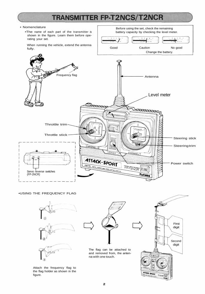
• Nomenclature•The name of each part of the transmitter is
shown in the figure. Learn them before ope-rating your set.
When running the vehicle, extend the antennafully.
Before using the set, check the remainingbattery capacity by checking the level meter.
Good Caution No goodChange the battery.
Frequency flag Antenna
Level meter
Throttle trim
Throttle stickSteering stick
Steering trim
Power switch
Servo reverse switches(FP-2NCR)
•USING THE FREQUENCY FLAG
Attach the frequency flag tothe flag holder as shown in thefigure.
The flag can be attached toand removed from, the anten-na with one touch.
Firstdigit
Seconddigit
2
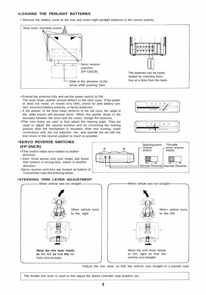
•LOADING THE PENLIGHT BATTERIES
• Remove the battery cover at the rear and insert eight penlight batteries in the correct polarity.
Rear cover mounting screws
Servo reverseswitches(FP-T2NCR)
Slide in the direction of thearrow while pushing here.
The batteries can be easilyloaded by inserting themfour at a time from the back.
• Extend the antenna fully and set the power switch to ON.The level meter pointer should deflect to the silver zone. If the point-er does not move, or moves very little, check for poor battery con-tact, incorrect battery polarity, or faulty batteries.
• If the pointer of the level meter deflects to the red zone, the range ofthe radio waves will become short. When the pointer drops to theboundary between the silver and red zones, change the batteries.
•The trim levers are used to fine adjust the steering angle. They areused to adjust the neutral position and for correcting the runningposture after the mechanism is mounted. After test running, makecorrections with the rod adjuster, etc. and operate the set with thetrim levers in the neutral position as much as possible.
•SERVO REVERSE SWITCHES(FP-2NCR)•This switch makes servo rotation to another-
direction.• After fixed servos onto your model, and found
that rotation is wrong-way, switch to anotherdirection.
•Servo reverse switches are located at bottom ofTransmitter case like drawing below:
•STEERING TRIM LEVER ADJUSTMENT
Steering servoreverseswitch
Normal Reverse Normal Reverse
Throttleservo reverseswitch
• When vehicle was run straight-
When vehicle turnsto the right
Move the trim lever slowlyto the left so that the ve-hicle runs straight.
When vehicle turnsto the left
Move the trim lever slowlyto the right so that thevehicle runs straight.
When vehicle was run straight.
*Adjust the trim lever so that the vehicle runs straight on a smooth road.
The throttle trim lever is used to fine adjust the speed controller stop position, etc.
3
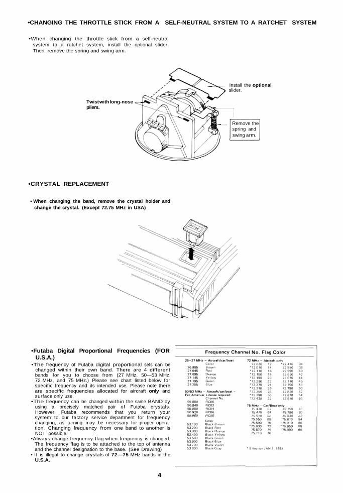
•CHANGING THE THROTTLE STICK FROM A SELF-NEUTRAL SYSTEM TO A RATCHET SYSTEM
•When changing the throttle stick from a self-neutralsystem to a ratchet system, install the optional slider.Then, remove the spring and swing arm.
Install the optionalslider.
Twist with long-nosepliers.
Remove thespring andswing arm.
•CRYSTAL REPLACEMENT
• When changing the band, remove the crystal holder andchange the crystal. (Except 72.75 MHz in USA)
•Futaba Digital Proportional Frequencies (FORU.S.A.)
•The frequency of Futaba digital proportional sets can bechanged within their own band. There are 4 differentbands for you to choose from (27 MHz, 50—53 MHz,72 MHz, and 75 MHz.) Please see chart listed below forspecific frequency and its intended use. Please note thereare specific frequencies allocated for aircraft only andsurface only use.
•The frequency can be changed within the same BAND byusing a precisely matched pair of Futaba crystals.However, Futaba recommends that you return yoursystem to our factory service department for frequencychanging, as turning may be necessary for proper opera-tion. Changing frequency from one band to another isNOT possible.
•Always change frequency flag when frequency is changed.The frequency flag is to be attached to the top of antennaand the channel designation to the base. (See Drawing)
• It is illegal to change crystals of 72—75 MHz bands in theU.S.A.
4
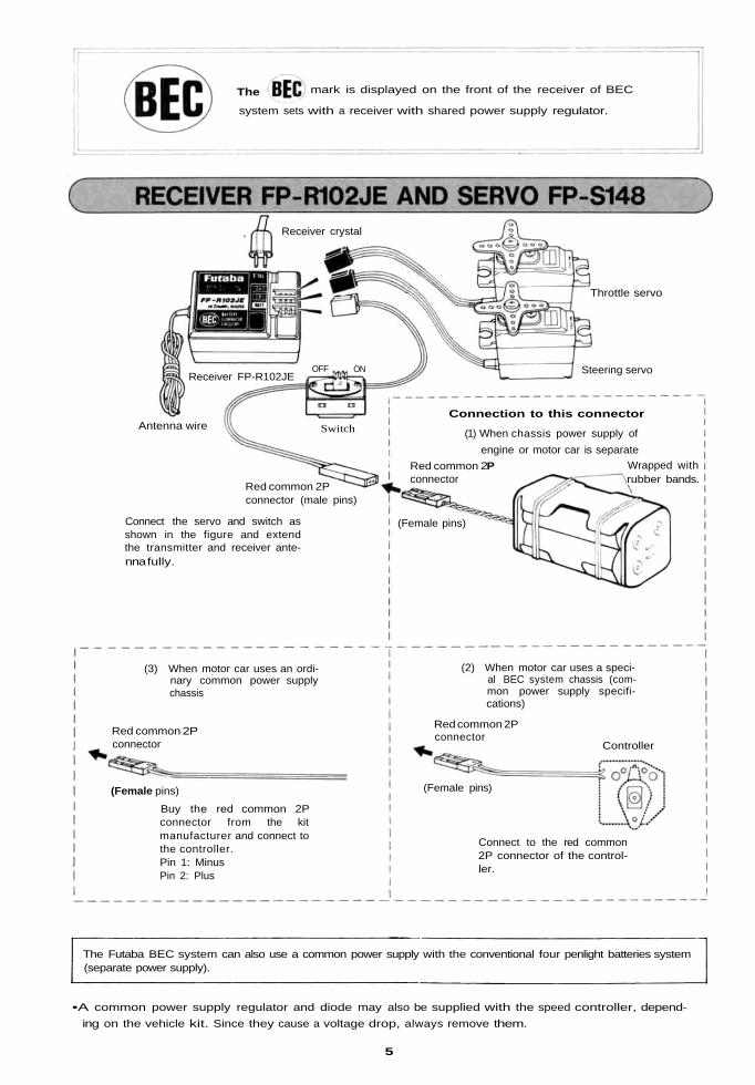
(3) When motor car uses an ordi-nary common power supplychassis
Red common 2Pconnector
(2) When motor car uses a speci-al BEC system chassis (com-mon power supply specifi-cations)
(Female pins)
Buy the red common 2Pconnector from the kitmanufacturer and connect tothe controller.Pin 1: MinusPin 2: Plus
Connect to the red common2P connector of the control-ler.
The mark is displayed on the front of the receiver of BEC
system sets with a receiver with shared power supply regulator.
Receiver crystal
Throttle servo
Steering servoReceiver FP-R102JE
Switch
OFF ON
Antenna wire
Red common 2Pconnector (male pins)
Connect the servo and switch asshown in the figure and extendthe transmitter and receiver ante-nna fully.
(Female pins)
Red common 2Pconnector
Wrapped withrubber bands.
Connection to this connector
(1) When chassis power supply ofengine or motor car is separate
Red common 2Pconnector
(Female pins)
Controller
The Futaba BEC system can also use a common power supply with the conventional four penlight batteries system(separate power supply).
•A common power supply regulator and diode may also be supplied with the speed controller, depend-ing on the vehicle kit. Since they cause a voltage drop, always remove them.
5
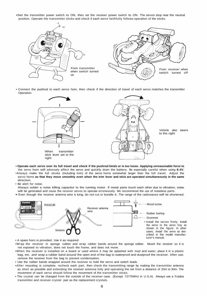
•Set the transmitter power switch to ON, then set the receiver power switch to ON. The servos stop near the neutralposition. Operate the transmitter sticks and check if each servo faithfully follows operation of the sticks.
From transmitterwhen switch turnedon
From receiver whenswitch turned off
• Connect the pushrod to each servo horn, then check if the direction of travel of each servo matches the transmitterOperation.
Vehicle also steersto the right
When transmitterstick lever set to theright
• Operate each servo over its full travel and check if the pushrod binds or is too loose. Applying unreasonable force tothe servo horn will adversely affect the servo and quickly drain the battery. Be especially careful when using 8.4V.
•Always make the full stroke (including trim) of the servo horns somewhat larger than the full travel. Adjust theservo horns so that they move smoothly even when the trim lever and stick are operated simultaneously in the samedirection.
• Be alert for noise.Always solder a noise killing capacitor to the running motor. If metal parts touch each other due to vibration, noisewill be generated and cause the receiver servos to operate erroneously. We recommend the use of noiseless parts.
• Even though the receiver antenna wire is long, do not cut or bundle it. The range of the radiowaves will be shortened.
Receiver antennawire
- Wood screw
• Install the servos firmly. Installthe servo to the servo tray asshown in the figure. In othercases, install the servo as des-cribed in the model manufac-turer's manual.
Rubber bushingGrommet
R102JE
Scissors
• A spare horn is provided. Use it as required.•Wrap the receiver in sponge rubber and wrap rubber bands around the sponge rubber. Mount the receiver so it is
not exposed to vibration, does not touch the frame, and does not move.•When the receiver is installed on a board or used where it may be splashed with mud and water, place it in a plastic
bag, etc. and wrap a rubber band around the open end of the bag to waterproof and dustproof the receiver. After use,remove the receiver from the bag to prevent condensation.
• Use the rubber bands wrapped around the receiver to hold the servo and switch leads.•After mounting is complete, recheck each part, then check the transmitting range by making the transmitter antenna
as short as possible and extending the receiver antenna fully and operating the set from a distance of 20m to 30m. Themovement of each servo should follow the movement of the transmitter sticks.
• The crystal can be changed from the outside of the receiver case. (Except 72/75MHz in U.S.A) Always use a Futabatransmitter and receiver crystal pair as the replacement crystals.
6
Your NEW FUTABA Digital Proportional R/C Sys-tern is guaranteed against defects in workmanshipand material for 180 days from the date of purchasewhen the attached registration card is returned tous within ten days of purchase.This Guarantee is null and void if the R/C systemhas been improperly handled, damaged in a crash, ortampered with and does not cover the replacementof plastic housings or electronic componentsdamaged due to the use of improper voltages.When service is required, please take your equip-ment to your local authorized service station or shipit directly to us. All postage, shipping, and insurancecharges must be paid by the user.
•When requesting repair of trouble that has oc-curred suddenly of from long use, describe thetrouble symptoms in as much detail as possible.This will facilitate detection of the trouble pointand shorten the repair period greatly.
•Defects caused by faulty materials or workmanshipwill be corrected free of charge.
•This limited warranty is null and void if the set hasbeen tampered with or disassembled.Refer to warranty statement for details.
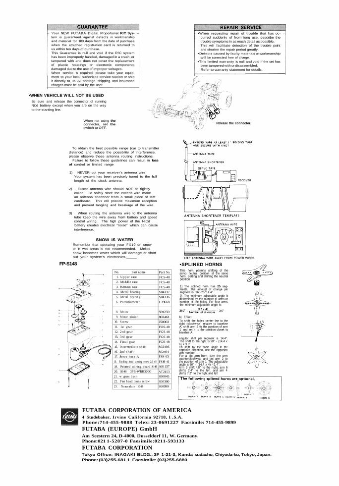
•WHEN VEHICLE WILL NOT BE USEDBe sure and release the connector of runningNicd battery except when you are on the wayto the starting line.
When not using theconnector, set theswitch to OFF.
Release the connector.
To obtain the best possible range (car to transmitterdistance) and reduce the possibility of interference,please observe these antenna routing instructions.
Failure to follow these guidelines can result in lossof control or limited range
1) NEVER cut your receiver's antenna wire.Your system has been precisely tuned to the fulllength of the stock antenna.
2) Excess antenna wire should NOT be tightlycoiled. To safely store the excess wire makean antenna shortener from a small piece of stiffcardboard. This will provide maximum receptionand prevent tangling and breakage of the wire.
3) When routing the antenna wire to the antennatube keep the wire away from battery and speedcontrol wiring. The high power of the NiCdbattery creates electrical "noise" which can causeinterference.
SNOW IS WATERRemember that operating your FX10 on snowor in wet areas is not recommended. Meltedsnow becomes water which will damage or shortout your system's electronics._____
FP-S148 •SPLINED HORNSThis horn permits shifting of theservo neutral position at the servohorn. Setting and shifting the neutralposition
1) The splined horn has 25 seg-ments. The amount of change persegment is; 360-25!e14.4°2) The minimum adjustable angle isdetermined by the number of arms ornumber of the holes. For four arms,the minimum adjustable angle is:
b) EffectTo shift the holes center line to theright (clockwise) relative to baselineA, shift arm 2 to the position of arm1 and set it to the position closet tobaseline A.
angular shift per segment is 14.4°.The shift to the right is 90° - (14.4 x6) = 3.6°To shift by the same angle in theopposite direction, use the oppositearm number.For a six arm horn, turn the armcounterclockwise and set arm 2 tothe position of arm 1. The adjustableangle is 60° - (14.4 x 4) =2.4°.Arm 3 shift 4.8° to the right, arm 6shifts 2.4° to the left, and aim 4shifts 7.2° to the right and left
No. Part name1. Upper case2. Middle case3. Bottom case4. Metal bearing5. Metal bearing6. Potentiometer
8. Motor9. Motor pinion
10. Screw11. 1st gear12. 2nd gear13. 3rd gear14. Final gear15. Intermediate shaft16. 2nd shaft17. Servo horn A18. Bind ing head tapping screw 2.6 x819. Printed wir ing board S14820. S148 3PB-WRB300G21. w gum bush22. Pan head truss screw23. Nameplate S148
Part No.FCS-48FCS-48FCS-48S04137S04136I 39668
S91259802461J50002FOS-48FGS-48FGS-48FGS-48S02495S02494FSH-6XFSH-4IAS1157AT2453S90045S50360S60099
FUTABA CORPORATION OF AMERICA4 Studebaker, Irvine California 92718, I .S.A.Phone:714-455-9888 Telex: 23-0691227 Facsimile: 714-455-9899FUTABA (EUROPE) GmbHAm Seestern 24, D-4000, Dusseldorf 11, W. Germany.Phone:021 1-5287-0 Faesimile:0211-593133FUTABA CORPORATIONTokyo Office: INAGAKI BLDG., 3F 1-21-3, Kanda sudacho, Chiyoda-ku, Tokyo, Japan.Phone: (03)255-681 1 Facsimile: (03)255-6880