Embed Size (px)
Citation preview

FutabaDIGITAL PROPORTIONALRADIO CONTROL
PCM1024ZAPCM1024ZHPULSE CODE MODULATION SYSTEM

Thank you for purchasinga Futaba digital proportional radio control set.
Please read this manual carefullybefore using your set.
ATTENTION:
1. Application of ProductThis product is not intended for use in any application other than for thecontrol of models for hobby and recreational purposes. This product issubject to regulations of the Ministry of Radio/Telecommunications and isrestricted under Japanese low to such purposes. The laws of other countriesmay similar ly res t r i c t the use of th is product . Futaba is notresponsible for any use that is not in compliance with applicable law.
2. Exportation of ProductIf the product is exported from Japan, the prior approval of the Ministry ofRadio/Telecommunications is required regarding the country of destination.If this product is reexported from other countries, it may be subject torestrictions on such reexport and prior approval of government authoritiesmay be required.
3. Modification, Adjustment & Replacement of PartsFutaba is not responsib le fo r any use of this product that is not incompliance with applicable law and disclaims all responsibility for any modi-fication or alteration of the product, including the incorporation of the prod-uct into other products by third parties, that is not in compliance with appli-cable law.
ATTENTION:The product that you have purchased contains a rechargeable battery.The battery is recyclable. At the end of its useful life, under various stateand local laws, it may be illegal to dispose of this battery into themunicipal waste stream. Check with your local solid waste officials fordetails in your area for recycling options or proper disposal. (For U.S.A.)Ni-Cd
THE FOLLOWING STATEMENT APPLIES TO THE RECEIVER
This device complies with part 15 of the FCC Rules.Operation is subject to the following two conditions:(1) This device may not cause harmful interference, and(2) This device must accept any interference received,
including interference that may cause undesired operation. (For U.S.A.)

Manual Introductory Section
TABLE OF CONTENTS
System Features . . . . . . . . . . . . . . . . . . . . . . 2Introduction . . . . . . . . . . . . . . . . . . . . . . . . 3System Usage . . . . . . . . . . . . . . . . . . . . . . . . 4Manual Layout . . . . . . . . . . . . . . . . . . . . . . . 6FLYING SAFETY . . . . . . . . . . . . . . . . . . . . . 7Notable System Features . . . . . . . . . . . . . . . . . 9
PCM 1024Z System Contents. . . . . . . . . . . . . . . 10Power-On Screen Displays . . . . . . . . . . . . . . . . . 11Working With The CAMPac Memory Module . . . . . .12Using The Soft Keys . . . . . . . . . . . . . . . . . . . . 13Operation Without Radio Transmission . . . . . . . . . 14System Monitor Lights & Warnings . . . . . . . . . . . . 14System Status and Alarm Displays . . . . . . . . . . . . 15Using Your Futaba System Contents. . . . . . . . . . . 16Radio Installation . . . . . . . . . . . . . . . . . . . . . 17Charging & Direct Servo Connect Operation . . . . . .18Stick Length Adjustment . . . . . . . . . . . . . . . . . 19Stick Tension Adjustment . . . . . . . . . . . . . . . . . 19
Stick Angle Adjustment . . . . . . . . . . . . . . . . . . 20Antenna Angle Adjustment . . . . . . . . . . . . . . . . 20Transmitter Battery Replacement . . . . . . . . . . . . 21Rubber Protective Pad Installation . . . . . . . . . . . . 21Transmitter RF Module . . . . . . . . . . . . . . . . . . 35Synthesized Frequency Module & Receiver . . . . . . .99Flight Condition Switching . . . . . . . . . . . . . . . . 23
SYSTEM MENUContents . . . . . . . . . . . . . . . . . . . . . . . . . . . 94MSL - Model Selection . . . . . . . . . . . . . . . . . . . 95
VLT - Battery Voltage Display. . . . . . . . . . . . . . . 26TAC - Tachometer . . . . . . . . . . . . . . . . . . . . . 97SRV - Servo Cycle & Bar Graph Display . . . . . . . . . 93TRN - Trainer System . . . . . . . . . . . . . . . . . . . 99
DTN - Data Transfer Function . . . . . . . . . . . . . . 30CPM - Copy Model Function . . . . . . . . . . . . . . . 31CPC - Copy Condition Function . . . . . . . . . . . . . 39PAR - Parameters (Sets Auto-Off and
Screen Contrast) . . . . . . . . . . . . . . . . . . 33UNA- User Name Registration . . . . . . . . . . . . . . 34FRO - Trans. Freq. Set . . . . . . . . . . . . . . . . . . 35Setting The Frequency Synthesizer Receiver . . . . . . 36SWT - Switch setting . . . . . . . . . . . . . . . . . . . . 37
PMX - Programmable mixing . . . . . . . . . . . . . . . 65STM - Subtrim . . . . . . . . . . . . . . . . . . . . . . . 68TOF - Trim offset . . . . . . . . . . . . . . . . . . . . . 69CNA - Condition naming . . . . . . . . . . . . . . . . . 70TRM • Digital trim . . . . . . . . . . . . . . . . . . . . . 71
AIRPLANE SECTION
Table of Contents . . . . . . . . . . . . . . . . . . . . . 73Airplane Controls & Functions . . . . . . . . . . . . . . 74Airplane Receiver and Servo Connections . . . . . . . . 76Airplane Setup Instructions . . . . . . . . . . . . . . . . 77Aileron Differential [ADF] . . . . . . . . . . . . . . . . 80Rudder Coupling [A—R] . . . . . . . . . . . . . . . . . 81V-Tail [VTL] . . . . . . . . . . . . . . . . . . . . . . . . 32Rudder—Aileron [R-A] . . . . . . . . . . . . . . . . . 83Elevons [EVN] . . . . . . . . . . . . . . . . . . . . . . . 84Elevator-»Flap [E—F] . . . . . . . . . . . . . . . . . . . 85Flap-Elevator mix [F—E] . . . . . . . . . . . . . . . . . 86Collective Pitch [CPT] . . . . . . . . . . . . . . . . . . 37Ailvators [ALV] . . . . . . . . . . . . . . . . . . . . . . 33Flaperons [FPN] . . . . . . . . . . . . . . . . . . . . . . 39Airbrake [ABK] . . . . . . . . . . . . . . . . . . . . . . 91Snap Roll [SNP] . . . . . . . . . . . . . . . . . . . . . . 93Throttle Curve Adj. (TCV) . . . . . . . . . . . . . . . . 94
HELICOPTER SECTIONTable of Contents . . . . . . . . . . . . . . . . . . . . . 95Helicopter Controls . . . . . . . . . . . . . . . . . . . . 96Helicopter Receiver and Servo Connections . . . . . . . 93Sample Helicopter Setup Instructions . . . . . . . . . . 99Pitch Curve [PCV] . . . . . . . . . . . . . . . . . . . . .104
Hovering Pitch [PHV] . . . . . . . . . . . . . . . . . . . 105Pitch Trim [PTM] . . . . . . . . . . . . . . . . . . . . . 106Throttle Curve [TCV] . . . . . . . . . . . . . . . . . . .107
Hovering Throttle [THV] . . . . . . . . . . . . . . . . . 108Hovering Offset [HOF] . . . . . . . . . . . . . . . . . . 109Throttle Hold [HLD] . . . . . . . . . . . . . . . . . . .110Swashplate Type [SWP] ...................................111Pitch—Rudder [P—R] . . . . . . . . . . . . . . . . . . .112Rudder—Throttle [R—T] . . . . . . . . . . . . . . . . . .113Gyro Sensitivity [GYR] . . . . . . . . . . . . . . . . . . 114Acceleration [ACC] ........................................115Inverted Pitch [INV] . . . . . . . . . . . . . . . . . . .117
MODEL SETTING SECTION
C o n t e n t s . . . . . . . . . . . . . . . . . . . . . . . . . . . 39CSL - Condition Select . . . . . . . . . . . . . . . . . . 40TIM - Timers & Elapsed Time Counter . . . . . . . . . 41
F/S - Failsafe/Hold Setting . . . . . . . . . . . . . . . . 42PMD - Pulse Mode FM/PCM . . . . . . . . . . . . . . . . 43REV -Servo Reversing Function . . . . . . . . . . . . . 44FNC - Function Control . . . . . . . . . . . . . . . . . . 45RST - Data Reset . . . . . . . . . . . . . . . . . . . . . . 46CUT - Engine Cut . . . . . . . . . . . . . . . . . . . . . 47CHD - Condition Hold . . . . . . . . . . . . . . . . . . . 48TYP - Model Type Selection . . . . . . . . . . . . . . . 49CH9- Channel 9 Switch Definition . . . . . . . . . . . 50MNA - Model Name Definition . . . . . . . . . . . . . . 51ALT - Alternate Switch . . . . . . . . . . . . . . . . . . 52THR - Throttle Curve . . . . . . . . . . . . . . . . . . . 53SWH -Swashplate Type . . . . . . . . . . . . . . . . . . 54RDR - Rotor Direction . . . . . . . . . . . . . . . . . . 56INV - Inverted Pitch . . . . . . . . . . . . . . . . . . . . 57
PIT - Pitch Curve . . . . . . . . . . . . . . . . . . . . . . 58
COMMON CONDITIONS
C o n t e n t s . . . . . . . . . . . . . . . . . . . . . . . . . . . 59
ATV - Adjustable travel volume & Channel delay . . . 60AFR - Adjustable function rate . . . . . . . . . . . . . . 62D/R - Dual rates & EXP curve. . . . . . . . . . . . . . . 64
SAILPLANE SECTIONTable of Contents . . . . . . . . . . . . . . . . . . . . . 118Sailplane Condition Menus . . . . . . . . . . . . . . . . 119
Sailplane Transmitter Controls and Functions . . . . .120Sailplane Receiver and Servo Connections . . . . . . .121Example Sailplane Setup Instructions . . . . . . . . . . 195Aileron Differential [ADF] . . . . . . . . . . . . . . . . 125Aileron—Rudder Mixing [A-R]. . . . . . . . . . . . . .126
Aileron-Speed Flap Coupling [ASF] . . . . ..........................127V-Tail [VTL] . . . . . . . . . . . . . . . . . . . . . . . .128Airbrake Mixing [ABE] . . . . . . . . . . . . . . . . . . 129Elevator—Brake Flap Mixing [EBF] . . . . . . . . . .... . 1 3 0
Elevator—Speed Flap Coupling (ESF) . . . . . . . . . .131Brake Flap Mixing [BKF] . . . . . . . . . . . . . . . . . . . . . . . .132Speed Flap Mixing . . . . . . . . . . . . . . . . . . . . . 135Speed Flap Trim [SFT] . . . . . . . . . . . . . . . . . . 139Butterfly Mixing [BFY] . . . . . . . . . . . . . . . . . . 140Butterfly Trim Mix [BYE] . . . . . . . . . . . . . . . . 142
Elevator Trim (ETM) . . . . . . . . . . . . . . . . . . . 143Trim Mix 1 [TM1] & Trim Mix 2 [TM2] - 4-S . . . . . 145Flap-Elevator mix [F—E] . . . . . . . . . . . . . . . . ..147Elevator-Flap Mix [E—F] . . . . . . . . . . . . . . . . . . 143Flaperon Mixing (FPN] - 2-S . . . . . . . . . . . . . . . 149
COMMAND LIST . . . . . . . . . . . . . . . . . . . . . 151
Manual Introductory Section, Page 1

Manual Introductory Section
Futaba's PCM 1024Z series of radio con-trol systems is the most sophisticated avail-able for aircraft, helicopters, and sailplanes.Inside this radio is the logic necessary tocontrol virtually any aircraft imaginable(both transmitter types are programmedfor all three aircraft).
Built into the system are a number ofmenus designed to make it simple to tailorthe system's programs for YOUR aircraft.Multiple menus provide unparalleled con-trol of every aspect of the model's setup,even some that you probably never thoughtof before!
System Features:• 1024 High resolution system• 9 Channels (select channel order)• 10-Model Memory• 8-Character Model names• 16 added memories with CAMPac Module• Up to 8 flight conditions for each model• 5 programmable mixers with special advanced
functions for each model setup• Each flight condition separately programmable• Flight condition & channel delay setting• Ready for aircraft, helicopters, and sailplanes• Deluxe carrying case included• Carrying handle• Ergonomic shape easy to hold and operate• Attractive neckstrap and mount• Ball bearing control sticks• Adjustable tension control sticks• Adjustable length control sticks• Adjustable angle control sticks• Programmable transmitter switches• Large liquid-crystal display• Contrast adjustment• Soft keys make programming simple• Switchable FM/PCM• Optional synthesized frequency module &
receiver• Unique Digital Trim function (2 rates)• Electronic servo centering, reversing, throw
volume, exponential• Failsafe/Hold setting• Powerful data copy functions• Swiveling antenna stores in transmitter• Detachable battery pack• Two separate timers & elapsed time counter• Automatic system power-off• Low-voltage alarm• Special Mixer alarm• Voltmeter with adjustable load for transmitter
and receiver batteries• Built-in tachometer• DSC System• Trainer system
Airplanes• Aileron Differential [ADF]• Rudder Coupling [AS-R]• V-tail [VTL]• Rudders-Aileron [R-A]• Elevons [EVN]• Elevators-Flap [E-F]• Flaps-Elevator [F-E]• Collective pitch [CPT]• Differential elevators [ELV]• Flaperons [FLP]• Airbrake [ABK]• Snap Roll [SNP]• Throttle Curve Adj. [TCV] (12 segment)
HelicoptersPitch Mixing [PCV]Hovering Pitch [PHV]Pitch Trim [PTM]Throttle Curve [TCV]Hovering Throttle [THV]Hovering Offset [HOF]Throttle Hold [HLD]Swashplate type [SWH]Pitch-Rudder [P-R]Rudder-Throttle [R-T]Gyro Sensitivity [GYR]Acceleration [ACC]Inverted Pitch [INV]Throttle curve adj. [THR]Rotor Direction [RDR]
Sailplanes (Select from 2, 4, or 5-servos in wing)• V-tail [VTL]• Differential adjustment [ADF]• Rudder coupling [A-R]• Aileron-flap coupling [ASF]• Airbrake/Spoiler/Gear trim compensation [ABE]• Elevator-flap coupling [EBF, ESF]• Flap trim setting [SFT]• Butterfly (Spoileron or Crow) [BFY]• Butterfly trim mix [BYE]• Elevator trim sets [ETM]• Flap-Elevator mix [F-E]• Elevator-Flap mix [E-F]• Flaperon mixing [FLP]
Manual Introductory Section, Page 2

Manual Introductory Section
INTRODUCTION
Thank you for selecting the Futaba®PCM1024Z Radio System. The design ofthis system has absolutely no compromises.You now possess a system that w i l l allowyou to fly your model — airplane, helicop-ter, or sailplane — with the highest per-formance possible. With a / / the power inthis system, setting up and adjusting is verysimple. We recommend that you read themanual carefully to learn about the pro-gramming features, but if you are in a hur-ry, follow the example set-up instructionsin the beginning of the model setup proce-dures sections. We have provided detailedexamples for power aircraft, helicopters,and sailplanes (with two, four, and fivewing servos).
The transmitter can be used with anymodel type by using the desired specialmixing menus for the model you are inter-ested in — a / / menus are contained in bothtypes of transmitters. The transmitters forairplanes and sailplanes (PCM 1024ZA)contain snap ro l l direction switches and adifferent throttle stick feel than the heli-copter system (PCM 1024ZH).
The PCM 1024ZA System Transmitteruses a unique menu system, which allowsthe utmost in versatility. In stead of a single,complicated loop that forces the user to"step through" each menu on the way tothe desired setting, the PCM 1024ZA allowsyou to proceed directly to the menu thatyou need, bypassing those that do not needany inputs. This system makes setting upmodels both rapid and simple.
You may define different groups of set-tings that may be called up by the settingof a single FLIGHT CONDITION switch.You may program up to eight differentflight conditions for each model in themain memory area.
The exclusive optional synthesized trans-mitter module and receiver allow you tochoose any frequency available withoutswitching crystals or modules, or changingreceivers. Electronically-activated trims arememorized for each model in memory, andcan't be accidentally moved while thetransmitter is off. The optional CAMPacMemory Module can store additional modelsetups and easily transfer them to otherPCM1024Z transmitters.
All in a l l , the Futaba PCM1024Z is themost advanced radio control system in theworld — we know that you enjoy using itfor pleasurable flying!
Manual Introductory Section, Page 3

Manual Introductory Section
SYSTEM USAGE
The PCM 1024Z system that you have justpurchased has been designed to be the most versa-tile radio system possible. Because of this, a fewwords about the layout of the radio are called for.You are already aware that the PCM 1024Z trans-mitter has numerous model memories, but it isimportant to understand that each model memorymay have several flight condition setups that maybe switched during flight! This means that youmay really call up different trim settings, mixing,and control feel as you fly the model. For exam-ple, an aircraft could have different takeoff andacrobatic settings; a helicopter could have differentsettings for hovering, aerobatics, and autorotation;a sailplane might be set up with independent set-tings for launching, thermal I ing, speed, and landing.Switching between these different settings is aseasy as flipping a switch.
To accommodate this power, the PCM 1024Zsystem has four levels of operation: the HomeMenu, the System Menu, the Model Menu, and theCondition Menu. The Home Menu appears whenthe system is first turned on, and displays suchitems as battery voltage, trim positions, one ormore timers, and other functions. The top leveldisplay is what is normally displayed during opera-tion.
The next level down is the System Menu. TheSystem Menu is used to choose and call up theitems that apply to all model setups stored withinthe PCM 1024Z transmitter. This menu includessuch items as Model Select (which chooses whichmodel setup to use), Copy Model and Copy Condi-tion, User Name inputting. Switch Setting, andother items.
Next comes the Model Menu, which containsunique information about each model stored with-in the PCM 1024Z's memory. Within this menu aresettings that pertain to a particular model. Ofcourse, these settings can vary for each differentmodel. As an example, the Model Menu containsthe Servo Reversing function, which may be dif-ferent for each model stored.
Finally, you will find the Condition Menus.These menus are customized to the different typesof models the PCM 1024Z system will accommo-date: Airplane, Helicopter, and Sailplane (thethree sailplane menus are further broken into thecategories of 5 wing servos, 4 wing servos, and 2wing servos). In the Condition Menus, you may setup throws, mixing functions, and other items thatvary with flight conditions but are associated withone model setup.
As mentioned earlier, the PCM 1024ZA SystemTransmitter uses a unique menu system, whichallows the utmost in versatility. The PCM 1024ZAallows you to proceed directly to the menu thatyou need, bypassing those that do not need anyinputs, instead of forcing the owner to proceedthrough a single, complicated loop one menu at atime on the way to the desired setting. This systemmakes setting up models both rapid and simple.
This menu configuration is illustrated below.
Manual Introductory Section, Page 4

Manual Introductory Section
Model Menu 1Settings forModel #1
Condition MenusSettings for allconditions for
Model #1
Condition #1Model #1
Condition #2Model #1
conditions 3-7
Condition #8Model #1
Startup MenuShows during
regular operation
System MenuSettings that apply to all
models in storage
Model Menu 2Settings forModel #2
Condition MenusSettings for allconditions for
Model #2
Condition #1Model #2
Condition #2Model #2
Manual Introductory Section, Page 5
Condition #8Model #2
Model Menu 10Settings forModel #10
Condition MenusSetting for allconditions for
Model #10
Condition #1Model #10
Condition #2Model #10
Condition #8Model #10

Manual Introductory Section
MANUAL LAYOUT
The instructions contained in this book arewritten in great detail so that you may easilyunderstand the capabilities of your PCM 1024Zsystem. We recommend that you spend some timereading these instructions so that you can have agood feel of what the system can do.
After this introduction are some words aboutsafety and proper operation of your Futabasystem. Next is a section on general operationalprinciples, including adjustments that you canmake on the transmitter to make it 'fit'your flyingstyle.
Next are instructions for system-level program-ming. This system-level programming is importantbecause it is used with all three types of modelsthat the PCM 1024Z system can be set up for. Thisincludes model menu selection, system voltmeteroperation, tachometer usage, servo bar graph dis-play, trainer setup, and model data transmissionand copying.
A section on general model settings follows.This section covers the topics of model setup thatare common to all model types, such as settingthrows, servo reversing, type selection, model nam-ing, and others. The remainder of the menus arespecific to the particular type of model.
After the general section is a list of the commoncondition menus that apply to all three types ofaircraft that the 1024A system can accommodate.This is followed by three sections which describethe setup procedures for aircraft, helicopters, andsailplanes. At the beginning of each model setupsection is an example setup procedure that de-scribes all the steps needed to set up all the desiredflight conditions for a model. Each of these sec-tions assume that you are familiar with the generalsystem-level operations sections.
The rear of the manual contains blank datatables that may be used to record the data thatyou have programmed into your system, and con-tains technical details of this system. Be sure tomake a photocopy of the blank data tables beforeyou write in them.
We hope that you find the PCM 1024Z SystemManual very hopeful. Please feel free to write toFutaba if you feel that any corrections or clarifica-tions should be made.
Manual Introductory Section, Page 6

Manual Introductory Section
FLYING SAFETY
Safety is very important when you are flyingradio-controlled models. If you fail to follow theinstallation, setup, and operation instructions inthis manual, or if you ignore warnings or rules setby others, you may cause the partial or total de-struction of your radio control system, aircraft,and endanger yourself or other persons or proper-ty. You are responsible for safe operation of yourmodel, and may be held liable for any damagesyour activities cause.
Please maintain your system properly. Install itin your aircraft using the proper procedures,inspect the model frequently for correct operationand structural and control authority, and be cer-tain that you are capable of handling the model inunusual situations. Do not fly over or near specta-tors or where your model could injure any personor property. Do not fly unless you are sure of yourflying skills, radio installation, and model integrity.Please ask for assistance from an experienced pilotif you are not sure about your qualifications.
Before flying, carry out a range check on the ground with thetransmitter antenna extended only one step. Note the distance youcan achieve without loss of control — it should be at least 30 paces.We recommend a range check before each flying session to verifythat your system is working properly.
When flying, be sure the antenna is fully extended. If the antennais not fully extended, your model's effective range is reduced, andinterference can cause difficulties even at short range.
Be sure that you do not shorten the receiver antenna, either bycutting some off, or by coiling the excess up. Instead, let the excesslength trail behind or below the aircraft. Cutting the antenna willreduce the effective range of the system and increase the chance ofinterference.
When turning on your radio system, first turn on the transmitter,then turn on the receiver. When turning off the power, turn off thereceiver first, then the transmitter. If these turn-on sequences are per-formed in reverse order, the receiver may pick up spurious signals andcause the servos to drive hard over, causing possible damage to theradio system and the control linkages.
Manual Introductory Section, Page 7

Manual Introductory Section
If you are using the Synthesized transmitter module FP-TK-FSS,be sure that you know the transmitting frequency before switchingon. If you don't know the frequency, hold the [A] or [R] key downas you switch on power. The transmitting frequency will be displayedbut radio transmission is deactivated. Once you have determined thefrequency, secure the appropriate frequency control device and turnon power to operate normally.
Be sure to charge the transmitter and receiver batteries fully. If thesystem has not been used for a long time, be sure to charge at least24 hours before using the system, and check both batteries with thesystem voltmeter at high load (500 mA). The transmitter batteryshould remain above 9.4 volts, and the receiver should be above 4.7volts. IF EITHER BATTERY INDICATES LOWER THAN THIS, DONOT FLY. Recharge the batteries first.
Do not quick charge the battery. Overcharging the battery willcause the battery to overheat and creates a very dangerous situation.
Recharge
Do not expose your system to rain or allow water to get inside thecase. If water does penetrate the case, control of the model could belost, resulting in a crash and danger to others. Use a waterproof coveror wait until the conditions are dry before attempting to fly.
Manual Introductory Section, Page 8

Manual Introductory Section
PCM 1024Z NOTABLE SYSTEM FEATURES
• The optional CAMPac memory module stores upto 10 model setups, and may be exchanged be-tween different PCM 1024Z transmitters so thatmodel data may be rapidly transferred, orbacked up.
• The telescoping antenna is stored within thetransmitter, but when it is extended, it may beeasily rotated in any direction using the sphericaljoint on the top of the transmitter case.
• Flight Condition Switching allows preset mixing,trims, and other data to be matched to existingflight conditions immediately upon movementof a user-defined switch. A programmable Delaycircuit makes smooth transitions between flightconditions. Each flight condition may have in-dependent values for trims, mixing authorities,and presets.
• Switch Function Position Modification functionallows the owner to set the position and functionof all sticks, knobs, sliders, and switches as hedesires.
• The Type Selection Function allows any PCM1024Z transmitter to be used for airplanes, heli-copters, or sailplanes. The model type may beselected from a menu screen.
• Exclusive Digital Trim function makes trimchanges easy to do, remembers the trim statusfor each model in memory, and prevents unin-tentional trim changes. Trim functions may beassigned to any stick or control.
• Large Liquid Crystal Display and Soft Keysmake model programming and data input easy.Inputs change memory instantly, so immediateverification of inputs is possible.
• The optional Frequency Synthesized Receiver(R309DPS) allows rapid frequency changes toeliminate frequency conflicts on crowded flyingfields.
• Programmable Trainer Function allows theinstructor to choose which functions are usedfor training, and a special feature allows simplecorrection by the instructor without disconnect-ing the student.
• Detachable Transmitter Battery Pack may beeasily removed from the transmitter and chargedseparately, or used as an independent spare.
These are fust a few of the outstanding PCM1024Z features. You can read about many more ofthe features in the manual. Please do so — or you'llnever know what you've missed !
Manual Introductory Section, Page 9

Manual Introductory Section
PCM 1024Z SYSTEM CONTENTS
Manual Introductory Section, Page 10

Manual Introductory Section
POWER ON SCREEN DISPLAYS
After the transmitter's power switch is turnedon, the current model number and name is dis-played (see next page for what happens on theinitial turn-on). Check to verify it is the desiredmodel, otherwise you will have to change it in theSystem menu. There may also be a caution mes-sage displayed for any special mix functions and/or non-default flight condition switches that areturned on. This caution message will be accompa-nied by a warning sound of six beeps repeatedevery two seconds, and will continue until the off-ending switch is deactivated. You may hit the END
key, or wait a few moments to display the startingscreen.
The Home screen displays the user's name, theactive model memory and flight condition, theTimer #1 display, the system voltages, and thetrim status. The selection keys to the variousmenus are also displayed. To switch to these dif-ferent screens, press the desired key A to R .BE SURE TO CHECK THE MODEL NAME ANDCONDITION BEFORE FLIGHT. One of the mostcommon crash causes is taking off with the wrongmodel setup loaded in the transmitter.
• Displayed for several seconds
- Currently selected modelnumber and name
• Immediate switch tostart screen
Manual Introductory Section, Page 11

Manual Introductory Section
WORKING WITH THE CAMPAC MEMORY MODULE
The optional CAMPac Memory Module can beused to store model setup data separately from thetransmitter. Its advanced electronic design needsno battery back-up power, so the CAMPac may beused to transfer data directly into another PCM1024Z system.
When the transmitter power switch is turned onfor the first time after the set is purchased, orwhen the power switch is turned on after thememory module has been changed, the "INI-TIALIZE EXT MEM?" message will appear at thecenter of the screen. Press the YES key to ini-tialize the memory module so it is ready to storedata.
The CAMPac can store and memorize as manyas 16 sets of model data, depending on the numberof flight conditions. When used in conjunctionwith the transmitter's 10-model memory, as manyas 26 different model setups may be permanentlystored. The table below gives the numbers ofmodel data that the CAMPac can store, whichdepends on the number of flight conditions. Whenpower is turned on, it may take some time to copycomplicated model and flight condition data intothe transmitter's memory. This normally takes justtwo or three seconds.
Number of flight conditions
1
2
3
4
5
67
8
Memorizable model data
169
6
5
4
3
3
2
Moving the CAMPac from one PCM 1024Ztransmitter to another is one way of transferringmodel setups from the first to the second. Another
way may be used with transmitters that do nothave the CAMPac installed. This method requiresan optional data transfer cord.
Manual Introductory Section, Page 12

Manual Introductory Section
USING THE SOFT KEYS
The soft keys are used to call up the differentmenus during operation and programming. Forexample, to call up the System Menu from thehome screen shown above, press the Q key (nextto the SYS label). Press the A to R keys thatcorrespond with the function names to get to thatparticular function. Whenever a key is pressed, youwill hear a confirmation beep.
Manual Introductory Section, Page 13

Manual Introductory Section
OPERATION WITHOUT RADIO TRAMSMISSION
If you'd like to make some small corrections toa setup OR find out what frequency the Synthe-sizer module is set for without radiating ANDwithout removing the transmitter RF module orusing the DSC cable, you can do this by turning onthe power switch while simultaneously holding theA or R keys. This may also be used to find outwhat frequency the synthesizer transmitter module
will be using. When you power up the system thisway, check to be sure that the "ON AIR" displayis not on. You can now set the data or check what-ever you need to. When you are done, you mayreset the transmitter by turning off the powerswitch. The transmitter will radiate normally onthe next turn-on.
SYSTEM MONITOR LIGHTS & WARNINGS
There are two indicator lights above the powerswitch on either side. The right-hand light flasheswhen the transmitter is transmitting, or if a flightcondition or mixing switch is activated. The left-hand indicator lights when the system power is on,and blinks during automatic data transfer.
In the airplane mode, either the Snap Roll[SNP] or the Airbrake [ABK] switches will lightthe indicator lights. For helicopters, Throttle Hold[HLD] or Inverted switches [INV] will causeflashing. In sailplanes, Butterfly mixing [BFY] willactivate the light.
You should also be aware that a beep soundsevery four seconds when Condition Hold [CHD] isoperating to remind you to turn it off. For yourconvenience, the left and right sliders on the sidesof the transmitters emit a beep whenever they areset at their center positions. This feature allowsyou to center them without having to take youreyes off of the model.
CAUTION!If you are using the Synthesized transmit-
ter module FP-TK-FSS, be sure that youknow the transmitting frequency beforeswitching on. If you don't know the fre-quency, hold the A or R key down as youswitch on power. The transmitting frequency
will be displayed but radio transmission isdeactivated. Once you have determined thefrequency, secure the appropriate frequencycontrol device and turn on power to operatenormally.
Manual Introductory Section, Page 14

Manual Introductory Section
SYSTEM STATUS AND ALARM DISPLAYS
The PCM 1024Z System provides you with anumber of indicators and displays to show youthat your system is operating correctly. This sec-tion will explain each display's function
EXT MEM ERR displayThis display blinks when a data error occurredduring transmission of data between the trans-
mitter memory and the memory module. Turnoff the power. DO NOT REMOVE OR INSERTTHE MEMORY MODULE WITH THE POWERTURNED ON. THIS ACTION COULD DE-STROY THE MODULE.
ON AIR display and beepThis display is turned on when radio waves arebeing transmitted.
Enter ID No. displayThis display indicates when the security modeis set. In this case, model data cannot bechanged. See the section on data protection toreset this display.
LOW BATTERY display and beepThis display and warning beep are to notify the operatorthat the transmitter battery is low.TO PREVENT PROBLEMS, LAND THE MODELAS SOON AS POSSIBLE.
PLL ERROR and beepThis display blinks and sounds when the synthesizedfrequency module is removed during operation.Be sure to turn off power before installing the module.Do not remove or insert the module with power on.
(D BACK-UP BATTERY FAILURE - DO NOT FLYThis warning is displayed when the data stored has beenlost for some reason. A beep will sound simultaneously.When the power switch is turned on again, the error dis-play goes off and the data returns to the factory defaultstate. The lithium data backup battery needs to be re-placed, or there is a fault in the system. Return thesystem to the Futaba service center for assistance. Thelife of the lithium battery varies, but is usually at leastfive years.
2 CURRENT MODEL IS** * ##.NAME ***This display shows the model number and model namecurrently stored in the active area of the transmitter. Itwill disappear a few seconds after the system is turned on.
DATA PAC IS MISSING - LOADED MODEL1This message is displayed whenever the transmitter isturned on with the memory module removed and theactive model data was stored on the module. Without thedesired model data, the system loads the Model 1 datainstead.
3 CAUTION: NON-DEFAULT COND IS ACTIVEThis warning message is displayed, and a beep sounds,whenever the transmitter is turned on with a flight con-dition switch activated. This display and alarm will turnoff as soon as the flight condition switch is turned off.
4 CAUTION: SPECIAL MIX FNCT IS ACTIVEThis message and alarm are activated when the transmitteris turned on with a mixing switch activated. The alarmmonitor above the power switch also blinks. All of thesewill stop as soon as the mix switch is changed to its OFFposition.
CAUTION: ENGINE CUT FNCT IS ACTIVEIf the power is turned on with the engine cut switch on,this message is displayed and a beep sounds. When theengine cut switch is turned off, the display and alarmstop.
Manual Introductory Section, Page 15

Manual Introductory Section
USING YOUR FUTABA SYSTEM
This section contains information on charging the batteries in yoursystem, and installing the airborne components in your model. We willalso tell you all the ways that you may customize your PCM 1024ZSystem mechanically, so it "feels right" in your hands.
Then, we will show you all the features that are used by all themodel types that may be controlled by the PCM 1024Z system. Thiswill include all the exclusive PCM 1024Z features, including timers,trim settings, voltmeter with load, direct-servo connect, and trainersystems.
Using Your Futaba System: Contents
Radio Installation . . . . . . . . . . . . . . . . . . . . . . . . . . . . . . . . 17Charging & Direct Servo Connect Operation . . . . . . . . . . . . . . 18Stick Length Adjustment . . . . . . . . . . . . . . . . . . . . . . . . . . . 19Stick Tension Adjustment . . . . . . . . . . . . . . . . . . . . . . . . . . 19Stick angle adjustment . . . . . . . . . . . . . . . . . . . . . . . . . . . . . 20Antenna Angle Adjustment . . . . . . . . . . . . . . . . . . . . . . . . . 20Rubber Protective Pad Installation . . . . . . . . . . . . . . . . . . . . . 21Transmitter Battery Replacement . . . . . . . . . . . . . . . . . . . . . 21Transmitter RF Module . . . . . . . . . . . . . . . . . . . . . . . . . . . . 22Optional Synthesized Frequency Module & Receiver(see caution message) . . . . . . . . . . . . . . . . . . . . . . . . . . . . . 22Flight Condition Switching . . . . . . . . . . . . . . . . . . . . . . . . . . 23
Manual Introductory Section, Page 16

Manual Introductory Section
RADIO INSTALLATION
Please observe the following precautions duringthe installation of the radio into your model andsubsequent flying activities:
Servo InstallationMount each servo snugly to a sturdy plywood
servo tray or use the provided mounting trays. Usethe supplied rubber grommets on the mountingears, and tighten the screws to hold things snuglybut try not to crush the grommets completely.If you squeeze them too much, their vibrationdampening characteristics will be reduced.
Receiver connectionsConnect the receiver, servos, switch, battery,
and gyro (if used) in accordance with the modelsetup directions given in the appropriate modelsections. For aircraft, see page 80. For helicopters,refer to page 104. For sailplanes and electrics, usepage 130.
Receiver InstallationWrap the receiver in cushioning foam rubber,
and place it in a sealed plastic bag to prevent itfrom fuel leaks or inadvertent water landings. Userubber bands wrapped around the receiver toprovide strain relief for the antenna, switch, andservo wiring. Secure with foam pieces on all sides.
Run the antenna down the inside of the fuse-lage, or secure it to the top of the vertical finwith a small rubber band. Do not shorten excessantenna wire, or tie it into a bundle. Reducedrange could result. If you experience problemswith an internal antenna, try routing it differently,or move it outside of the model fuselage.
Switch Harness InstallationWhen you install the switch harness, be sure
that the rectangular hole is slightly longer than thefull switch stroke, so that it moves smoothly fromOn to Off and vice versa. Try to install the switchon the opposite side from the engine exhaust, andaway from dust or dirt.
System and Servo Operation CheckTurn on the transmitter power first, then the
receiver power. Be sure that the transmitter anten-na is fully extended. All servos will travel to theirneutral positions. Operate the transmitter sticks,knobs, and levers individually and be sure that theappropriate servo follows the control movement.If a servo does not move as it should, first check tosee that it is plugged into the correct receiver out-put. If it is not, move it to the correct output. If itis in the correct location, verify that you haveactivated the appropriate mixing functions.
Now, connect each servo with its pushrod.Again move each transmitter control in succession,verifying that control movement is the properdirection. If a servo does not move in the properdirection, use the reversing function [REV] in theModel menu.
Servo Throw AdjustmentOperate each control over its full travel, and
check that the servos don't bind and that there areno loose connections. If the servo does bind, thecurrent drain will be very high, and your batterywill not last for much time. This exposes a risk ofcrashing due to a low receiver battery.
Make sure that the servo can move its entirethrow amounts (including trim) without bindinganywhere. If necessary, use the Adjustable ThrowVolume [ATV] menu to reduce servo travel so itdoes not bind.
Range CheckAfter installation is complete, perform a ground
range check by extending the transmitter antenna onlyone step. With the receiver antenna full length, step25-50 paces from the model. The servos shouldoperate normally at this distance. Continue walkingaway until control is lost, and note the approximatedistance. This is your ground range, and should berepeated before each flying session.
Electrical NoiseElectrical noise is created by the touching of
two metal parts, and creates "static" similar tothat heard on an AM radio during a thunderstorm.Your Futaba radio set is resistant to electricalnoise, but no set may be made completely im-mune. For best flying range, avoid metal-to-metalcontact wherever possible.
Manual Introductory Section, Page 17

Manual Introductory Section
CHARGING & DIRECT SERVO CONNECT OPERATION
Battery ChargingYour Futaba FP-9ZAP and -9ZAH system is
equipped with rechargeable Nickel-Cadmium bat-teries. The figure shows the necessary connectionsfor charging the transmitter and receiver batterypacks. Both packs may be charged at the sametime or they may be charged individually. Thecharging connections bypass the power switches,so the set will not operate even if switched on.
The minimum recommended charge time for aspent battery is 15 hours, but it will not damagethe batteries to charge them longer. However, if
the battery has not been used for some time, itmay take several charge/discharge cycles beforethe battery resumes its full-capacity flight dura-tion.
When fully charged, the system will provideapproximately 60-80 minutes of flying time,providing there is no stalling of the servos. Be sureto check the state of the receiver battery frequent-ly with the built-in voltmeter function [VLT] inthe System menu. If the receiver battery dropsbelow 4.4 volts under load, do not attempt to fly.
Direct Servo Connect (DSC) Cord ConnectionUsing the DSC system, you may directly con-
nect the transmitter to the receiver without havingto transmit radio waves. This feature can be ex-tremely useful for adjusting any settings on themodel without worrying about frequency clear-ance. Additionally, with the receiver off, the DSCcord may be used to measure the receiver batteryvoltage (for this display, see VLT in the Systemmenu).
also be used for charging). To operate, plug theDSC cable into the receiver jack, then plug theround DIN connector into the back of the trans-mitter. Switch on the receiver ONLY — not thetransmitter.
To check the receiver battery voltage, switchoff the receiver and move to the VLT menu in theSystem area. You may apply different currentloads to assess the condition of the receiver bat-tery. When you are through with DSC and/orReceiver battery monitoring, remove the DINconnector from the rear of the transmitter.
When you wish to use the DSC system, you willneed to install the accessory DSC/Charge Cordinto the side of the model fuselage (this cord may
Manual Introductory Section, Page 18

Manual Introductory Section
STICK LENGTH ADJUSTMENT
The sticks on your PCM 1024Z System featurenon-slip ends, and the length may be adjusted tobe most comfortable for the pilot. To change sticklength, unlock the stick tip by turning counter-
clockwise. Move the tip to the desired position,and then lock to length by moving the lockingpiece upwards counterclockwise.
Non-Slip Stick Tip Locking piece
STICK TENSION ADJUSTMENT
You may easily adjust the tension in the PCM1024Z sticks to suit your personal preferences. Toadjust, you will need to get access to the adjust-ment screws in the back of the transmitter.
Gently pull up on the rubber grip and remove itfrom the rear of the transmitter. Then, use a small
cross-point screwdriver to change the length of thesprings which tightens or loosens them. Be carefulnot to push too hard, as it is possible to damagethe inside of the transmitter. Always turn offtransmitter power before adjusting stick tension.
Aileron Rudder
Manual Introductory Section, Page 19
Elevator(Mode 1)
Elevator (Model)
Manual Introductory Section
STICK ANGLE ADJUSTMENT
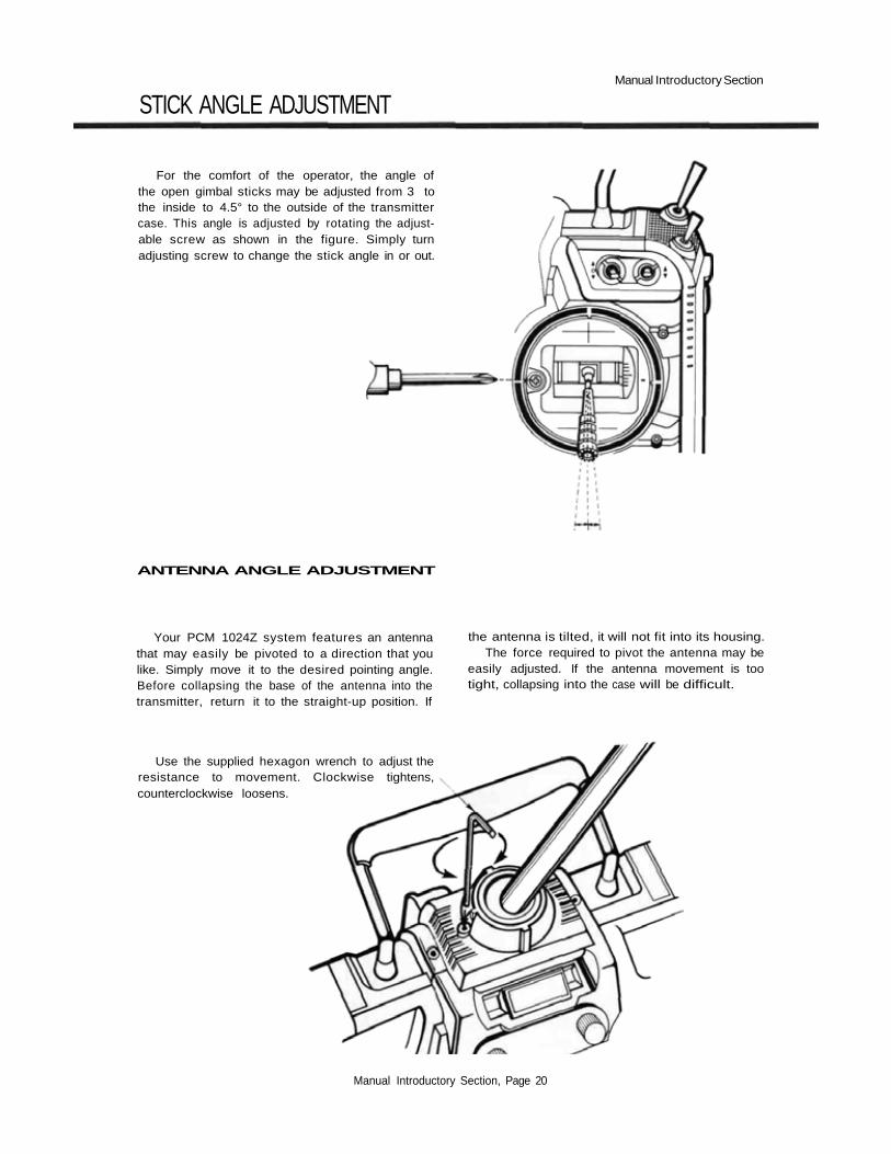
For the comfort of the operator, the angle ofthe open gimbal sticks may be adjusted from 3 tothe inside to 4.5° to the outside of the transmittercase. This angle is adjusted by rotating the adjust-able screw as shown in the figure. Simply turnadjusting screw to change the stick angle in or out.
ANTENNA ANGLE ADJUSTMENT
Your PCM 1024Z system features an antennathat may easily be pivoted to a direction that youlike. Simply move it to the desired pointing angle.Before collapsing the base of the antenna into thetransmitter, return it to the straight-up position. If
the antenna is tilted, it will not fit into its housing.The force required to pivot the antenna may be
easily adjusted. If the antenna movement is tootight, collapsing into the case will be difficult.
Use the supplied hexagon wrench to adjust theresistance to movement. Clockwise tightens,counterclockwise loosens.
Manual Introductory Section, Page 20

Manual Introductory Section
TRANSMITTER BATTERY REPLACEMENT
Battery Cover
RUBBER PROTECTIVE PAD INSTALLATION
The transmitter battery is easily removed andreplaced, making it simple to have a spare batterypack for extended flying duration.
Open the battery cover and remove the re-chargeable battery pack by pulling outward on theribbon. Be careful not to damage the battery coveror drop the battery pack.
We recommend that rubber protection pads beinstalled in case the transmitter is ever rested on itsback.
Double-sided tape
Stick the double-sidedtape to the inside of theprotection pad
Repeat for other side.
Stick the protection pads to theshaded area of the transmitter.
RF Module
Manual Introductory Section, Page 21

Manual Introductory Section
TRANSMITTER RF MODULE
The PCM 1024Z transmitter is designed to workwith either the FP-TK-FM or the FP-TK-FSS fre-quency-synthesized Radio Frequency (RF) mod-ules. Other modules may not be used.
It is normal for the module's temperature torise during operation.
To remove the module, pressinwards on the top and bottomtabs and simultaneously pull themodule away from the rear of thetransmitter.
OPTIONAL SYNTHESIZED FREQUENCY MODULE & RECEIVER
The R309DPS synthesized-frequency receiverand matching transmitter frequency module aresupplied with the PCM1024ZAPS and PCM1024ZHPS systems. The transmitting and receivingfrequency may be easily changed without remov-ing any crystals or exchanging frequency modules.The ability to rapidly change frequency is a greatadvantage on a crowded flying field or in contestentry.
The receiver will also work with any otherFutaba 1024 systems. For more information onthe synthesized system, refer to page 37.
CAUTIONIf you are using the Synthesized transmit-
ter module FP-TK-FSS, be sure that youknow the transmitting frequency beforeswitching on. If you don't know the fre-quency, hold the A or R key down as youswitch on power. The transmitting frequencywill be displayed but radio transmission is de-activated. Once you have determined the fre-quency, secure the appropriate frequencycontrol device and turn on power to operatenormally.
Manual Introductory Section, Page 22

Manual Introductory Section
FLIGHT CONDITION SWITCHING
Flight control switching is among the mostpowerful features available in your PCM 1024Zsystem. It is a function that allows you to changevirtually all the models' trims, mix settings, andresponses with the flick of a switch — while yourmodel is airborne! You can think of this as ameans of switching between as many as eight dif-ferent model setups as you desire.
All the mixing and deflection angles can bechanged during flight condition switching. Youmay pick and choose those settings that result inthe best flight characteristics for your model, andleave the rest alone.
As an example, you may set up different condi-tions corresponding to varying crosswind situa-tions, or you can have different response "feels",like a reduced control authority for smootherlandings. You may call up an entire group ofsettings for a snap roll on a single switch. Helicop-ters may be set up for best response for aerobaticsand autorotation. Sailplanes may have settingsmatched to the very different flight conditions forlaunching, normal cruise, speed, distance, andlanding.
You may think of the different condition set-tings as sheets of paper in a folder, and the trans-mitter as an envelope with a clear window. As youselect each flight condition, you see its parametersthrough the window, and not those of the others.Each "sheet" can have completely different set-tings on it.
Manual Introductory Section, Page 23

System Section
SYSTEM MENU
The following controls and menus are used for system-wide settings.These are settings that are stored for, or may be used for any and allof the different model setups stored in the PCM 1024Z's memory.
To select any of these keys, first select the horizontal line contain-
ing the item you wish to select, using the B or C keys adjacent to
the left-hand side of the screen. Then, select the desired item with the
F to L keys underneath the display.
Select Line WithThese Keys
To Home Screen
To Model Menu
To Condition Menu
Function Selection Keys
Listed below are the contents of the System Settings Menu:
System Menu ContentsItem_______Definition____________ Function PageMSL . . .Model Selection . . . . . . . . .Use to load desired model's . . . . . 25
settingsVLT. . . .Voltmeter . . . . . . . . . . . .Use adjustable load to . . . . . . . . 26
check batteriesTAC. . . .Tachometer . . . . . . . . . . .Measures propeller rotational . . . . 27
speedSRV . . .Servo Test & Bar . . . . . . . .Displays servo positions . . . . . . . 28
Graph Display and cyclesTRN . . .Trainer System . . . . . . . . .Sets desired instructional. . . . . . . 29
channelsDTN . . .Data Transfer Function . . . .Copies model data to ano the r . . . . 30
1024ZCPM . . .Copy Model Function . . . . .Copies a setup into a second. . . . . 31
memoryCPC. . . .Copy Condition Function . . .Copies a single condition to . . . . . 32
anotherPAR. . . .Parameters. . . . . . . . . . . .Sets Auto-Off and Screen . . . . . . 33
ContrastUNA . . .User Name Registration . . . .Set up your name & security . . . . 34
codeFRQ . . .Transmitter Frequency. . . . .1024ZAPS/HPS Synthesized . . . . 35
Setting systems only (See CAUTIONmessage)
Setting The Frequency Synthesizer. . . .Choosing the desired frequency . . . 36ReceiverSWT . . .Switch Setting. . . . . . . . . .Use to define switch to. . . . . . . . 37
activate functions
System Section, Page 24

System Section
MS L—MODEL SELECTION
This function is used to load the settings of the
desired model into the PCM 1024Z's memory. The
settings may be selected from either the trans-
mitter's built-in memories, or from an optional
CAMPac. Remember that up to 10 memories are
available in the transmitter, and as many as 16 may
be stored in the CAMPac. The CAMPac is not
loaded with default models initially; they must be
loaded with the Copy Model [CPM] function.
Model Memory Selection Keys
Selected ModelNo. and Name
Transmitter Model Memory ListActive Model No. and Name
END returns toSystem Menu
To load a desired model from internal transmitter
memory to the active area:1. Select the desired model number with the A to J
( 1 to 1 0 ) keys2. Press the L ( YES ) key if correct, otherwise use the
M ( NO ) key to start over. Verify that the chosenmodel number and name is now shown in the display'stop center.
3. Finish by pressing the N ( END ) key.
To load a desired model from CAMPac memory
module to the active area:1. Press the P ( NXT ) key to display the first ten
models in the memory module's contents. Press itagain to get the remaining models. To return to theprevious model list, press ( PRE ) . Select thedesired model number with the A to J (11 to 20 or21 to 26 ) keys.
2. Press the L ( YES ) key if correct, otherwise use theM ( NO ) key to start over. Verify that the chosenmodel number and name is now shown in the display'stop center.
3. Finish by pressing the N ( END ) key.
To DELETE a desired model from CAMPac mem-
ory module:1. Press the P ( NXT ) key to display the first ten
models in the memory module's contents. Press itagain to get the remaining models. To return to theprevious model list, press ( PRE ). Select thedesired model number with the A to J ( 11 to 20 or
21to 26 ) keys.2. Press the L ( YES ) key if correct, otherwise use the
R( DEL ) key to start over. Verify that the chosenmodel number and name is now shown in the display'stop center.
3. Press the R ( DEL ) key.4. If this is the correct model to delete, press the
L ( YES ) key. To choose another, press the M( NO ) key.
5. Verify the deletion from the model list. Then, exit bypressing the N ( END ) key.
System Section, Page 25
System Section
VLT—BATTERY VOLTAGE DISPLAY
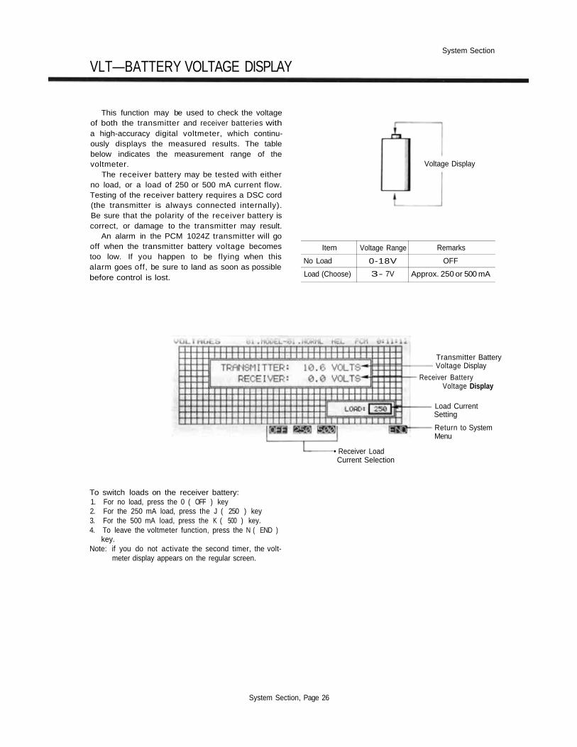
This function may be used to check the voltageof both the transmitter and receiver batteries witha high-accuracy digital voltmeter, which continu-ously displays the measured results. The tablebelow indicates the measurement range of thevoltmeter.
The receiver battery may be tested with eitherno load, or a load of 250 or 500 mA current flow.Testing of the receiver battery requires a DSC cord(the transmitter is always connected internally).Be sure that the polarity of the receiver battery iscorrect, or damage to the transmitter may result.
An alarm in the PCM 1024Z transmitter will gooff when the transmitter battery voltage becomestoo low. If you happen to be flying when thisalarm goes off, be sure to land as soon as possiblebefore control is lost.
Voltage Display
Item
No Load
Load (Choose)
Voltage Range
0-18V
3- 7V
Remarks
OFF
Approx. 250 or 500 mA
Transmitter BatteryVoltage Display
Receiver BatteryVoltage Display
Load CurrentSetting
Return to SystemMenu
• Receiver LoadCurrent Selection
To switch loads on the receiver battery:1. For no load, press the 0 ( OFF ) key2. For the 250 mA load, press the J ( 250 ) key3. For the 500 mA load, press the K ( 500 ) key.4. To leave the voltmeter function, press the N ( END )
key.Note: if you do not activate the second timer, the volt-
meter display appears on the regular screen.
System Section, Page 26

System Section
TAC—TACHOMETER
The tachometer function in the PCM 1024Z
transmitter may be conveniently used to measure
the rotational speed of any propeller or rotor
blade, up to a maximum of 50,000 RPM. This is
very useful for testing engine performance, rotor
settings, etc. If you like, you may have the TAC
display always appear on the Home screen.
Speed
Activates TAC displayin Home screen
RPM Display
Home ScreenDisplay Indicator
No. of Blades
Return to SystemMenu
Keys to Select No. of Blades
To choose the number of blades on the propeller, use the
G to L ( 1 to 6 ) keys. To display the TAC display onthe Home screen, press the E (DSP) key. This keytoggles the display on or off. Use the N (END) key toexit the TAC display.
Propeller Speed Measurement1. BE VERY CAREFUL IN THE VICINITY OF THE
PROPELLER. KEEP YOUR HANDS AND ALLEQUIPMENT AWAY FROM THE TURNING PROP.
2, Point the sensor, which is located in the left-hand sideof the PCM 1024Z transmitter, towards the propeller.Read the measured rotational speed. You may have tochange the relative orientation to get a steady reading.
NOTE: Fluorescent lights in the vicinity of thepropeller can produce erroneous readings. Ifyou can't make your measurements out-doors, use an incandescent light or flashlightto get a true reading.
System Section, Page 27

System Section
SRV—SERVO CYCLE & BAR GRAPH DISPLAY
This key has two different functions: a servocycling mode, which slowly moves each servo toits extreme positions, and a servo bar graph indi-cation, which pictorially shows the position towhich each servo is being commanded. The servotest function is useful for finding unevenness inservos, and the bar graph function may be used forroughly setting up models without using a receiveror servos. This can be particularly handy in settingup models with complicated mixing functions,because the results of each stick, lever, knob,switch input and delay circuit may be immediatelyseen.
The servo bar graph display is always operatingin this mode. To activate the servo cycling func-tion, first turn on the airborne system. Press theE (ON) key to start the servo cycling mode,and use the F (OFF) key to stop the cycling.
When using the Bar Graph display to set up amodel or mix, be sure to verify that all controlsmove the proper directions when actuated. De-pending on servo orientation, it is possible that thebar graph may indicate what appears to be thecorrect directions of throw when one or moreservos actually need reversing.
Use the END key N to leave this functionand return to the System Menu.
Check Servos By Cycling
Check Functions and Mixing
Turn Servo Test On & Off With These Keys
System Section, Page 28
Bar Graph Display
Return to
System Menu

System Section
TRN—TRAINER SYSTEM
The Trainer function makes it possible for theinstructor pilot to choose which functions andchannels are to be used for instruction, making itpossible to match the training difficulty to thestudent's skill level. A special function called Cor-rection Control makes it possible for the instructorto make corrections without overriding the stu-dent's inputs. Two transmitters must be connectedby an optional Trainer/Data Transfer cord, and theInstructor transmitter should be programmed fortrainer operation, as described below.
Operation is simple: when the Instructor acti-vates the trainer switch, the Student has control of
the aircraft (if the mixing mode is turned on, theInstructor can make corrections while the studenthas control). When the Instructor releases theswitch, control is regained. This is very usefulwhen the Student gets the aircraft into an undesir-able situation.
The training system will work with any PCM1024Z series transmitter. Futaba's 5U and 7Useries of transmitters may also be connected for astudent's usage. Note that in some cases a lowbattery warning may appear on the 7U series, butoperation is unaffected by this warning.
- ACT/ INH Selection
Return to SystemMenu
Channel Selection Keys
ON/OFF ToggleSwitch Setting
Instructor-ControlledChannel Selection
Correction MixingChannel Selection
TRAINER MODE SETUPTo place the PCM 1024Z into the Trainer mode, press
the TRN key from the System Menu. The Rkey succes-sively toggles between ACTIVATE and INHIBIT, with thecurrent mode displayed just to the left of the key. Onceactivated, the operation mode for each channel is selected.PLACE THE STUDENT TRANSMITTER IN PPM PULSEMODE. The instructor's transmitter may be in any trans-mission mode.
Controls and functions in both transmitters should bematched. With two PCM 1024Z transmitters, matchingmay be done easily using the Data Transfer DTN keydescribed on page 30. When using 5U and 7U transmitters,be sure that EACH transmitter command works properlybefore flying. All channel assignments and throw direc-tions must be identical.
The Instructor's power switch should be turned on,with its antenna fully extended. The student's transmitterswitch must always be turned off. In addition, the studentmust not operate his trainer switch, or problems mayoccur.
CHANNEL SELECTIONSelect the desired channel using the E to L up-arrow
keys. At this point, one can choose from student-onlycontrol and correction control. For Student-only control,press the P (TRN) key. This will cause the lowersquare in the chosen channel to become filled. For Cor-rection control, press the (MIX) key. This actionfills in the upper square in the active channel. If neithersquare is filled, only the instructor can control this partic-ular function.
SETTING UP THE ON/OFF SWITCHThe default switch for the trainer ON/OFF function is
the spring-loaded switch SW(H), with forward in the ONposition. This switch must be held ON continuously forthe student to have control. For convenience, the alter-nate switch function (ALT) may be used to set this switchso that it is alternately turned on and off successivelyeach time the switch is operated.
The location of the activation switch, as well as itsdirection and operation, may changed using the switchsetting screen available by pressing the O (SWT) key.For more details on the switch setting menu, see page 37.
System Section, Page 29

System Section
DTN—DATA TRANSFER FUNCTION
This function may be used to exchange model
setup data between two PCM 1024Z transmitters.
Identical model setups are needed for trainer oper-
ation, and it is also useful to transfer data to a
friend's transmitter to speed the setup process for
a model with complicated mixing and flight
modes, to avoid doing the setup process from
scratch.
An optional Trainer/Data Transfer Cable is
necessary for this operation. The time needed to
transfer data depends on the number of flight con-
ditions, and ranges from 1 to 18 seconds.
Data Transfer Mode Setup
First, connect the two PCM 1024Z transmitters
with the data transfer cord. To place the PCM
1024Z into the Data Transfer mode, press the
DTN key from the System Menu. Then, follow
the following instructions (if you want to start
over the beginning, press the abort ABT key L.
Model Memory Menu
Transmit Receive
Return to SystemMenu
Source Transmitter(with the desired model setup
stored in its memory)
1. Press the TRN ( K ) key.2. Select the Source model (to be
copied) with the A to J ( 1to10 ) keys.
6. Press the TNS ( K ) key tohave the Source transmitter sendthe desired data.
7a A successful transfer displays themessage "TRANSMITTING . . .COMPLETED". If an error isgenerated, the display will read"ERROR:DATA FAULTPLEASE RETRY".
8. To continue data transfer, pressthe CNT ( L ) key. To end, pressEND (N).
Destination Transmitter(to be loaded with the setups from
the Source transmitter)
3. Press the RCV ( L ) key.4. Use the A to J keys ( 1 to 10 )
to select the memory in which thesource model is to be stored.
5. Press the RCV ( K ) key toplace the Destination transmitterinto the receive mode.
7b When the data transfer issuccessful, the message"RECEIVING . . . COMPLETED"is displayed. If an error isgenerated, the display will read"ERROR:DATA FAULT PLEASERETRY".
8. To continue data transfer, press theCNT ( L ) key. To end, press END(N).
Trainer/Data Transfer CordConnector
System Section, Page 30
Target Transmitter

System Section
CPM—COPY MODEL FUNCTION
This function is used to copy one set of model
data into a second memory within the same trans-
mitter. This function is very handy because it may
be used for getting a head-start on setting up
models with almost the same settings (only differ-
ences need to be modified, instead of entering the
whole thing from scratch). Also, this function may
be used to make a backup copy of a model setup
before making changes.
The CPM function may be used to copy to and
from the optional CAMPac as well. The number of
models that may be stored in the CAMPac depends
on the number of flight conditions each contains.
This relationship is shown in detail on page 12.
Model Memory Menu
Source Model Name
Destination ModelName
Return to System MenuModel Memory Selection Keys
Usage of the Copy Model Function(Note: source and destination may be both in transmitter, both in CAMPac, orone in each)
Transmitter
1a Select the Source model withthe A to J ( 1 to 10 ) keys.
2a Select the Destination modelwith the A to J (1 to 10 )
keys.
3. To copy all the flight conditions, press the ALL ( M ) key.To copy just the default flight condition, press the DEF ( L ) key.
4. • If you are satisfied with your choices, press the YES (L) key. Thisexecutes the copy function, which may take anywhere from 2 to 18seconds. A beep indicates completion. Verify that the data were copiedunder the destination model name.
• If you wish to repeat the select on process, press the NO ( M ) key.
5. To continue copying, press the YES ( L ) key and repeat beginning atstep 1.To end the process and return to the System Menu. press the END ( N )key.
Optional CAMPac Memory Module
1b Press the NXT ( P ) key to get tothe CAMPac (model nos. 11 to 20 );press the NXT (P ) key again toget to models 21-26. Select thedesired Source model with the A toJ( 11 to20 or21 to26 ) keys.
2b Press the NXT (P ) key to get tothe CAMPac (model nos. 11 to 20);press the NXT ( P ) key again toget to models 21—26. Select thedesired Destination model with the
A to J (11 to 20 or 21 to26)keys.
System Section, Page 31
System Section
CPC—COPY Condition Function
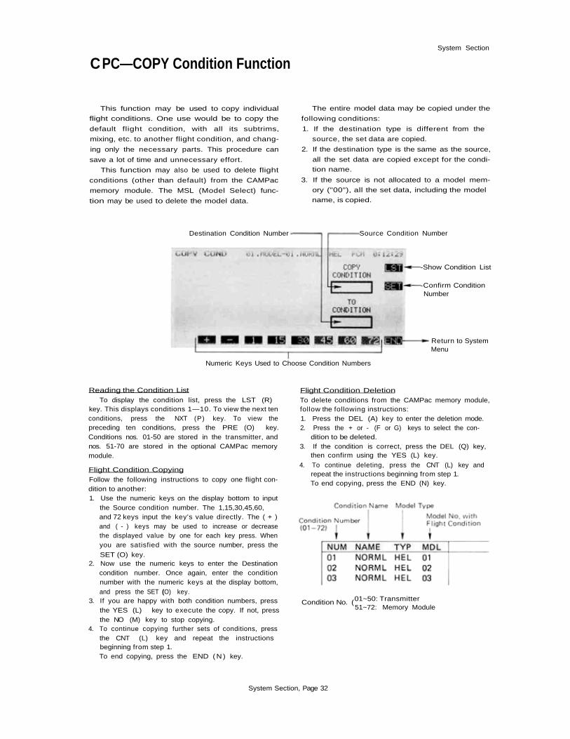
This function may be used to copy individual
flight conditions. One use would be to copy the
default flight condition, with all its subtrims,
mixing, etc. to another flight condition, and chang-
ing only the necessary parts. This procedure can
save a lot of time and unnecessary effort.
This function may also be used to delete flight
conditions (other than default) from the CAMPac
memory module. The MSL (Model Select) func-
tion may be used to delete the model data.
The entire model data may be copied under the
following conditions:
1. If the destination type is different from the
source, the set data are copied.
2. If the destination type is the same as the source,
all the set data are copied except for the condi-
tion name.
3. If the source is not allocated to a model mem-
ory ("00"), all the set data, including the model
name, is copied.
Destination Condition Number - Source Condition Number
-Show Condition List
-Confirm ConditionNumber
Return to SystemMenu
Numeric Keys Used to Choose Condition Numbers
Reading the Condition List
To display the condition list, press the LST (R)key. This displays conditions 1—10. To view the next tenconditions, press the NXT (P) key. To view thepreceding ten conditions, press the PRE (O) key.Conditions nos. 01-50 are stored in the transmitter, andnos. 51-70 are stored in the optional CAMPac memorymodule.
Flight Condition Copying
Follow the following instructions to copy one flight con-dition to another:1. Use the numeric keys on the display bottom to input
the Source condition number. The 1,15,30,45,60,and 72 keys input the key's value directly. The ( + )and ( - ) keys may be used to increase or decreasethe displayed value by one for each key press. Whenyou are satisfied with the source number, press the
SET (O) key.2. Now use the numeric keys to enter the Destination
condition number. Once again, enter the conditionnumber with the numeric keys at the display bottom,and press the SET (O) key.
3. If you are happy with both condition numbers, pressthe YES (L) key to execute the copy. If not, pressthe NO (M) key to stop copying.
4. To continue copying further sets of conditions, pressthe CNT (L) key and repeat the instructionsbeginning from step 1.To end copying, press the END ( N ) key.
Flight Condition Deletion
To delete conditions from the CAMPac memory module,follow the following instructions:1. Press the DEL (A) key to enter the deletion mode.2. Press the + or - (F or G) keys to select the con-
dition to be deleted.3. If the condition is correct, press the DEL (Q) key,
then confirm using the YES (L) key.
4. To continue deleting, press the CNT (L) key andrepeat the instructions beginning from step 1.To end copying, press the END (N) key.
Condition No. (01~50: Transmitter51~72: Memory Module
System Section, Page 32

PAR— PARAMETERS(SETS AUTO-OFF AND SCREEN CONTRAST)
System Section
This menu has two functions: the first auto-matically turns off transmitter power after acertain (settable) period of transmitter inactivity,and the second may be used to adjust the contrastof the liquid crystal display.
The Auto-Off function is designed to keep thetransmitter battery from becoming fully discharg-
ed if left on accidentally. The delay period untilshutdown may be selected from 10 to 40 minutesin ten minute increments, or the power off func-tion may be deactivated.
The Screen Contrast function may be adjustedwithin a ±10% range.
Auto-Off Display
Screen ContrastAdjustment
Auto-Off Time-Setting Keys Return to System Menu
Parameter Adjustment1. To set the delay for the Auto-Off function, press the
upper arrow A key.Select the desired time by pressing the10,20,30, or40 keys, or set the inhibit using the INH key (notrecommended).Exit the Auto-Off function by pressing the END(N ) key.
2. To set the Display contrast, press the lower arrow(B ) key.Use the + and - keys ( F or G ) to select thedesired level of contrast, -10% is bright, while+10% isdark.Exit the Contrast function by pressing the END(N ) key.
System Section, Page 33

System Section
UNA—USER NAME REGISTRATION
This function allows the user to enter his name,
up to ten characters long, into a memory. The
entered name is displayed on the top left corner of
the Home and menu screens of the transmitter.
Additionally, a special password feature allows
the user to define a four-digit password to protect
the model memory contents. Without entering the
correct password, model setups may not be
changed or entered. A second password may be
defined to protect the username entry only.
Unless you really need to, we recommend
against using the passwords. If the password is
forgotten, you will be unable to make any changes
to your system, and you'll have to return the unit
to Futaba to be reset.
Registering a User NameTo register the desired User Name, you must do the
following: first, press the A arrow key to select the reg-istration function. If necessary, move the cursor to thebeginning of the username with the G and I keys (left-and right-arrow).
Select the line containing the desired character withthe O to R keys. Now, use the K and M keys to moveacross the line until the cursor is underneath the desiredcharacter. To enter the character into the User Name line.press the ENT H key. Repeat this procedure for theremaining characters of the desired name. To make cor-ections to entered characters, use the G and I keys tomove to the character to be changed, and enter a newone.
When the name entry is completed, press the ENDN key.
Registering a User ID NumberPress the C key to begin the User ID Registration
function. To enter a System Password, choose the SYSGkey. To enter a Username password, press the NAME Ikey.
Select the User ID Registration function by pressingthe B key. Then, move the cursor to the beginning of theUser ID line with the left- and right-arrow keys (G) andI). Select the line containing the desired character withthe O to R keys. Now, use the K and M keys to moveacross the line until the cursor is underneath the desiredcharacter. To enter the character into the User Name line,
press the SET H key. Repeat this procedure for theremaining characters of the desired name. When theregistration is complete, press the SET E key. then usethe END (N) key to exit.
Operating a Transmitter With User ID RegisteredTurn on the power switch, then press the CNT K
key to get the user ID setting screen. Now you must enterthe User ID. Select the line containing the correct ID
character with the O to R keys. Next, use the K andEl keys to move across the line until the cursor is under-neath the desired character. Press the ENT H key toenter the character. Repeat this procedure for the remain-ing characters of the User ID. When the registration iscomplete, press the SET E key, then use the END(N) key to exit.
To Reset a System ID NumberFirst, you must use the procedure given in the previous
paragraph to get in, except do not exit. You will insteadreset the ID number to 0000 (four zeroes). Move thecursor to the zero (0, not 0) key, then press the ENTH key four times to enter "OOOO." Press the SET E-key, and exit with the END N key.
To Reset a Username ID NumberFirst, you must call the Username ID setting screen.
Enter all the registered characters as described before,and press the END N key. Move the cursor to thezero (0. not O ) key. then press the ENT H key fourtimes to enter "0000." Press the SET E key.
System Section, Page 34

FRQ—TRANSMITTER FREQUENCY SETTING(9ZAPS/HPS ONLY)
System Section
The exclusive Frequency Synthesizer SystemModule (FP-TK-FSS) allows you to switch yourtransmission frequency in software! No longer doyou have to carry around a module and receiverfor each frequency, or a carton of crystals! Youmay choose from any of the frequencies in the 72MHz band, channel numbers 11 through 60(72.010 to 72.990 MHz).
When you activate the FRQ function, the dis-play shows the frequency list with channels 11through 20 displayed. To display the next tenchannels, press the NXT (R) key; to show theprevious ten channels, press the PRE (Q) key.
To select the transmit frequency, first locatethe desired frequency using the procedure above.Then, select the desired channel number with thechannel selection keys A to J. It the selectedchannel is the correct one, verify by pressing theSet (O) key.
It is necessary to cycle the transmitter's powerto broadcast on the selected frequency. When youdo this, the channel number and frequency are dis-played on the Home Screen. READ THE WARN-ING BELOW BEFORE TURNING ON.
WARNINGIBe sure that you know the frequency your trans-mitter is set to broadcast on BEFORE you turn iton. If you are unsure what the frequency is, holdeither the A or R keys and turn on the transmitter.The transmit frequency will be displayed on theHome Screen. Then, turn off the transmitter andturn it on again when you have the proper frequencycontrol in your possession.
To View Next10 ChannelsTo View Previous10 ChannelsPress if IncorrectChannel ChosenUse to ConfirmChannel SettingReturn toSystem Menu
Use To Select Desired Channel No. Displays the Selected Frequency& Channel Number
System Section, Page 35

System Section
SETTING THE FREQUENCY SYNTHESIZER RECEIVER
The following procedure should be followed inorder to change the receiving frequency on a syn-thesized receiver.
First, turn off receiver power. Next, open thereceiver's dust cover by sliding in the directionshown by the arrow in the figure. Set the channelnumber by moving the two rotary switches to thedesired frequency numbers. For example, to setchannel 20, set the left switch to 2 and the rightswitch to 0. When setting is complete, close thedust cover.
When the receiver is turned on, the frequencyset by the rotary switches is used by the receiver.If the switch is changed during operation, thechanges will be ignored until the receiver is power-ed down and later turned on, at which time thenew frequency will be used.
Fifty frequencies, from Channel 11 to 60(72.010 to 72.990 MHz) can be set. If a channeloutside this range is set, the receiver will default toChannel 11.
Frequency Synthesizer ReceiverFP-R309DPS
Dust Cover
Dust CoverSliding Direction
First Digit Second Digitof Channel of ChannelSetting No. Setting No.
Channel No. Setting Switches
System Section, Page 36

System Section
SWT—SWITCHING SETTING
This function may be used to define whichswitch activates a particular function. The versatili-ty of the PCM 1024Z system allows you to defineswitches for the following purposes: special mix-ing, flight conditions, and timers. If you wouldrather have a control stick to have a switching
SWITCH SETTING SCREEN
function, this may be done also! You can makeany motion of any switch or stick on the trans-mitter activate or deactivate any switchable func-tion. Finally, for certain functions, you maycontrol the volume settings by adjusting one ofthe knobs or sliders.
System Section, Page 37

System Section
Setting the Activation SwitchFrom many different commands, the switch setting
function may be displayed by pressing the SWT ( P )key. This causes a pictorial display of the availableswitches to be displayed, as shown in the figure. In thiscase, the Timer function will be used as an example.
The A-H keys are used to select a particular switchlocation (in case you are confused about a switch's loca-tion, each is labeled with its letter key). Once you pressthe desired key location, the switch will be darkened onthe display. If you press the NUL key, switch activationis disabled.
Once selected, you must choose the position of theswitch which defines the ON or OFF position. This isdone by pressing one of the two (or three, if a 3-positionswitch) left-arrow keys P to R. If you are satisfied withthe choice, press the PRE ( N ) key to get back to theprevious screen. If you have used the Timer as an exam-ple, the switch you have chosen will be displayed atthe bottom of the timer definition area (if no switch ischosen, "**" is displayed).
Setting STICK ActivationIf you would rather have your on/off function con-
trolled by the motion of one of the transmitter sticks,press the STK (O) button while in the switch settingdisplay. This displays the STICK SET function in thelower part of the figure.
Use the J1 to J4 (A to D) buttons to select thedesired stick. Now, you will need to define the position atwhich the switching occurs. To do this, hold the stick inthe desired location and press the SET (Q) key.Finally, select the ON/OFF direction by pressing the+/- (P) key (note that the ACT and INH posi-tions swap each time the button is pressed). When you aredone setting up the stick switching, return to the originalsetting screen with the PRE (N) key.
Setting Volume ControlsSome functions may be controlled by either stick
position or knobs/sliders (for example. Pitch Curve in theHelicopter setup). In these functions, the VOL key willappear at (O). Press the VOL key to get to the settingscreen. You may select the desired function to be set withthe right and left-arrow keys (A and R). Next, use the
F, H, J , or L keys to define which control selects thevolume. Now you must use the +/- key to choose theoperating direction of the control. Use the PRE key toreturn to the previous menu.
The same procedure may be used if a stick control,rather than a slider or knob, is desired. In this case youwill select the stick and direction as given earlier for the"Setting Stick Activation" section above.
System Section, Page 38

Model Setting Section
MODEL SETTING SECTION
The following controls and menus are used for model settings.
These are settings that may be used individually for any and all of the
different model setups stored in the PCM 1024Z's memory. Each
model setup can have different model settings — for example, each
model may have different servos reversed, its own name, different
transmission type (PCM or PPM/FM), etc.
To get to these settings, press the MDL key from any menu. To
select one, first select the line containing the desired function with the
B, C, or D keys. Then use the F to L keys to select the function
to be entered.
The last five functions in the list below are only appropriate to
powered models.
Select Line WithThese Keys
To Home Screen
To System Menu
To Condition Menu
Function Selection Keys
Model Setting Section ContentsItem Definition Function PageCSL. . . .Condition Select . . . . . . . .Use to select flight condition . . . . 40TIM. . . .Timer Function . . . . . . . . .Sets up different timer modes. . . . 41
& displaysF/S . . . .Failsafe Function . . . . . . . .Defines servo positions when . . . . 42
signals are lostPMD . .Pulse Mode. . . . . . . . . . . .Select Transmission mode, . . . . . 43
PCM orPPM/FMREV . . .Servo Reversing Function . . .Use to reverse the throw . . . . . . . 44
directionsFNC . . .Function Change . . . . . . . .Use to define which control. . . . . 45
moves which function
RST. . . .Data Reset. . . . . . . . . . . .Use to clear & reset different . . . . 46portions of memory
CUT . . .Engine Cut. . . . . . . . . . . .Makes stopping engine safe . . . . . 47and easy
CHD . . .Condition Hold . . . . . . . . .Limits throttle when adjusting . . . 48flight conditions
TYP. . . .Type Selection Function. . . .Select Airplane, Heli, or . . . . . . . 49Sailplane model type
CH9. . . .Channel 9 Switch . . . . . . . .Defines location and function. . . . 50Definition of Channel 9
MNA . . .Model Name Definition . . . .May be used to identify model . . . 51setups
ALT. . . .Alternate Switch . . . . . . . .Defines actions for trainer. . . . . . 52switch
THR . . .Throttle Curve. . . . . . . . . .Adjusts throttle servo response (A.H) 53SWH . . .Swashplate Type . . . . . . . .Used to input geometry of. . . . . . 54
swashplate (H)RDR . . .Rotor Direction. . . . . . . . .Defines the rotor rotation . . . . . . . 56
direction (H)INV. . . .Inverted Pitch . . . . . . . . . .Sets inverted pitch response of . . . 57
helicopter (H)
PIT . . . .Pitch Curve . . . . . . . . . . .Defines helicopter pitch . . . . . . . 58response (H)
A = Applies to Airplane mode only. H = Appears with Helicopter models only.
Model Setting Section, Page 39

Model Setting Section
CSL—CONDITION SELECT
One of the most powerful features of theFutaba PCM 1024Z system is the ability to allocateas many as eight different flight conditions to asingle model memory. It is possible to define dif-ferent values of mixing, trims, neutrals, and otherfunctions for each flight condition, making it pos-sible to choose from eight different aircraft setupswhile flying one model! You may have differingflight conditions automatically called up by a pre-defined position of a stick, knob, lever, or switch.This command may also be used to define whatswitches and/or controls are used to activate eachflight condition.
The CSL function automatically allocates fourflight conditions to the Airplane, Helicopter(NORML, IDLE-UP 1&2, and THROTTLE HOLD)and Sailplane (define NORML, START, SPEED,and Landing) model types. However, each flightcondition must be activated and assigned to aswitch. Condition D is the default condition, alsoreferred to as NORML, and is the only one active
when a new model type is defined. This conditionis always on, and remains on until other conditionsare activated by switches.
The PCM 1024Z system maintains each flightcondition separately, and the same condition maynot be used by two different models — they musthave separate ones (of course, you may use theCPC copy function to make an identical flightcondition for the second model).
Also, for a particular model, you cannot havemodel conditions stored in both the transmitterand the CAMPac — they must all be in one or theother. You may store any type of flight conditionsin the CAMPac.
Setting Up Flight ConditionsThe allocation of a flight condition to a particularmodel memory has two steps:1. Select an unused flight condition number and activate
it;2. Define the activation switch and the ON position you
want.
Set of Flight Conditionsfor Chosen Model
Flight ConditionSelection Keys
Flight Condition Name
Flight Condition Number
• This key calls up theLIST of all flightconditions
• Return To ModelMenu
"00-NULL" indicates anunselected condition
Flight Condition AllocationTo allocate flight conditions to a particular model
memory, first check for an unused condition in the flight
conditions list. Press the LST (Q) key to display thislist. Model No. 00 indicates an unused flight condition.Conditions 01—50 reside within the transmitter, and con-ditions 51—72 are stored within the external memorymodule (optional). Conditions 1—10 are the default ornormal conditions for models 1—10.
To view the next ten conditions, press the NXT(P) key; to view the previous ten, press the PRE(O) key. You may return to the setting screen by pres-sing the END (N) key.
Now you select the flight condition you wish todefine; select this with the 2 to 8 (B to H) keys(remember that the Default condition cannot be chang-ed). Next, enter the number of the unused flight condi-
tion using the numeric keys. The numeric keys allow youto choose a number very near to the desired one, thenyou may use the + and - keys (F and G) to increaseor decrease the displayed number by one. You can use theNUL (H) key to reset the number to an unselectedstate.
Next you press the SET (O) key to set the condi-tion. If you get a warning "CONDITION IN USE CAN-NOT ASSIGN" you must go back and choose another,unused condition.
Activation Switch DefinitionCall the switch setting screen by pressing the SWT
(P) key. Next, set the desired switch position and ONdirection with the appropriate buttons (for a descriptionof the switch setting function, see p.37). Use the END( N ) key to complete the setting.
Model Setting Section, Page 40

Model Setting Section
TIM—TIMERS & ELAPSED TIME COUNTER
The Timer function may be set for any desiredtime, i.e. engine run time, specified times for com-petitions, etc. Two independent timers are provid-ed for your use. The timers are stored indepen-dently with each model, meaning that when youswitch between model setups, the timer associatedwith the new model is brought up automatically.
The timers may be set to start and stop fromthe soft keys, or from the motion of any switch orstick. You may set the ON and OFF directionsfreely. Each timer has a capacity of up to 59minutes 59 seconds. You may set the timer fromeither the Home Display or the Model Menu, usingthe TIM key.
Each timer may be set for countdown or count-up operation with a target time. If a target time isset and the timer reaches the set time, a buzzersound for each count is generated. Countdowntimers sound two short beeps during the last tenseconds before reaching the target, then a longtone at the target time, and continue countingwhile displaying a minus ( - ) sign. Count up timersalso beep the last ten seconds, beep the targettime, and keep counting upwards until shut down.
Setting Up TimersTo select the timer you wish to set, use the SEL
(R) button. This key toggles between the two timers,Next, choose either an up or down timer using the UP
and DWN (L and M) keys.Set your desired target time by pressing the SET
(G) key. This calls up the timer-setting keys on thescreen bottom. You may input the desired number ofminutes by pressing any of the number keys, then adjust-
ing with the + (F) and - (G) keys. To adjust theseconds value, press the minute/second M/S (E) keyonce. To get back to the minute setting, press M/Sagain.
The timer you have just set will now work on thestart/stop (S/S) keys (B and D). If you'd like tohave a switch or stick position turn them on and off, press
the SWT key (P) now. Then use either the switchsetting or stick setting menu to set the desired switch orstick (for more info, see page 37).
You may choose whether Timer 2 is displayed on thehome screen. To display it, press the DSP (J) key.The Timer 2 display is turned on and off alternately asthis key is pressed.
When you are satisfied with all the timer setups, pressthe END (N) key to return to the home menu.
Timer OperationsTo start and stop Timers 1 and 2, press the S/S keys
(A and D respectively). Each time the Start/Stop key ispressed, the timer stops (if running) or starts ( i f stopped).To reset the two timers, press the RST keys (B andC).
Model Setting Section, Page 41

Model Setting Section
F/S—FAILSAFE/HOLD SETTING
The Failsafe function may be used to set up
positions that the servos move to in the case of
radio interference. This function only works with
PCM receivers (FM receivers do not have the fail-
safe capability).
You may set either of two positions for each
channel: normal, where the servo maintains its last
commanded position, or Failsafe, where each servo
moves to a predetermined position. You may
choose either mode for each channel.
The PCM 1024Z system also provides you with
an advanced battery monitoring function that
warns you when the receiver battery has only a
little power remaining. In this case, the throttle is
moved to the defined failsafe position, or if one
was not defined, to a medium speed position. The
throttle may be released by operating a predefined
control on the transmitter (the default is throttle),
do not continue to fly — land as soon as possible.
Remember, if your throttle suddenly moves to a
position you did not command, land at once and
use the voltmeter function, with a 250 or 500 mA
load, to check your receiver battery. Quite a few
models have been saved from unnecessary crashes,
thanks to the battery failsafe function.
Failsafe Setting ProcedureIn the Model Menu, press the Failsafe key (F/S) to
get the Failsafe menu shown below.
Servo FailsafePosition
Battery FailsafeRelease
Normal/FailsafeSelection Keys
Position Setting Key
Return to ModelMenu
Channel Selection Keys
Now you must decide which channels you want to goto preset positions, and which you want to maintain theirlast commanded position.
Use the Up-Arrow keys (F to M) to select thedesired channel. Now, press the F/S key to switch thatchannel to the failsafe mode. Hold the stick, knob, orslider at the desired position and press the SET (O)key. The chosen servo command is now displayed inpercent underneath the selected channel buttons.
If you wish to reset the channel to the normal (hold)function, press the NOR (Q) key. If you desire thefailsafe function later, the last setting is remembered anddisplayed when the F/S key is again activated.
If you want the Battery Failsafe function to move thethrottle to a defined position, be sure to set it before youleave this menu.
Battery Failsafe Release FunctionThis function releases the throttle from is held posi-
tion after indicating that your receiver battery is low. Youdid remember to set a throttle failsafe position, didn'tyou? REMEMBER TO LAND AS SOON AS POSSIBLE.
Call the Battery Failsafe setting screen by pressing theBFS (R) key while in the Failsafe menu. Now, youmay choose that moving the throttle resets the condition,or select another stick or switch deactivates it.
To set a desired throttle release position, move thethrottle stick to the point at which you wish the failsafeto be released (perhaps low throttle but a bit above idle).Now press the SET (Q) button to set this position(the position is displayed in percent).
If you want to use another function to switch off thebattery failsafe, either choose the desired stick motion, ormove to the switch setting menu by pressing SWT (O).For more information on the switch setting menu, referto page 37.
When you are through setting all the desired channels,press the END key (N ) to return to the Model Menu.
Model Setting Section, Page 42

Model Setting SectionPMD—PULSE MODE(SWITCHING FM/PCM)
The PMD function allows you to select thetransmission mode that your PCM 1024Z uses.You may select between PCM (Pulse Code Modula-tion) and PPM (Pulse Position Modulation, alsocommonly called FM). Of course, the choice
depends on the type of receiver being used. If youchange the mode of transmission, you need tocycle the power switch Off and the On before itwill operate in the chosen mode.
Transmission Setting ProcedureIn the Model Menu, press the Pulse Mode key (PMD)
to get the Pulse Mode menu shown below.
Currently Active Transmission Mode
Chosen TransmissionMode
Return to ModelMenu
Transmission Mode Selection keys
Now, simply select the desired mode by pressing eitherthe PCM key (F) or the PPM (G) keys. Press theEND (N) key to leave the PMD command. To operatethe transmitter in the new mode, turn power off and thenon again.
Model Setting Section, Page 43

Model Setting Section
REV—SERVO REVERSING FUNCTION
This function is used to reverse the direction a
servo operates for a given command. This function
should be used AFTER any special menus are de-
fined to assure that all servos are moving the cor-
rect directions.
Direction SelectionKeys
NOR = NormalREV = Reverse
Return to the Model Menu
Channel Selection Keys
Reversing ProcedureAfter defining a new model, be sure to define all
special menus (such as Flaperons, Aileron-Speed Flapmixing. Differential, etc.). Be sure that all servos areplugged into the proper receiver channels. Now, deter-mine whether you need to reverse any channels by mov-ing each stick and observing the corresponding movementin the model's controls.
In the Model Menu, press the reverse function key(REV) to get the Reversing menu shown below.
Now you must choose which channels you want toreverse. Use the Up-Arrow keys (E M) to select thedesired channels.
Once you have selected the desired channel, use theNOR (Q) key and the REV (P) key to choose theproper direction for the servo. Repeat for each servoneeding reversal.
When done, press the END ( N ) key to return tothe Model Menu.
Model Setting Section, Page 44

Model Setting Section
FMC—FUNCTION CONTROL
The Function Control Menu may be used to
define the relationship between the transmitter
controls and the receiver output channels. Any
function on the transmitter may control any
receiver output channel. It is not necessary to
change the servo connections in the receiver.
This function is useful for changing the control
items for certain functions. For example, you may
wish to set the sailplane Butterfly function on the
throttle stick (J3) rather than on the default KnobA.
You may also use this function to select the
trim positions, independently from the sticks. For
instance, to set cross trims, simply exchange the
elevator (CH2) and throttle (CH3) trim positions.
One advantage of cross trims is that it is possibleto set the elevator trim without releasing the eleva-
tor stick, by using the other hand. The default
mode for the PCM 1024Z system is for cross trims.
Control Modification ProcedureIn the Model Menu, press the FNC key to get the
function modification menu.
Exit and Return to ModelMenu
Press to SelectChannel
Press to ModifyFunctions
Press to Modify Trims
Reverses OperationDirection
Channel Selection Keys
Use the SEL (O) key to make the channel selec-tion keys appear, then select the desired channel with thechannel select keys E to L on the screen bottom.
To change the control, press the CTR (P) key.Now you may select the desired control source from theStick, Control, or Switch keys. The bottom of the displayshows the keys LS , LD , RD , RS (Left Slider, Left Dial,Right Dial, Right Slider) followed byJ1,J2,J3, J4 (rightstick horizontal, right stick vertical, left stick vetical,left stick vertical, left stick horizontal). If you want to usea switch as an input instead, hit the NXT (M) key andSwitches A through H are displayed. If you wish to haveno function for a certain control, press NXT again andselect the NUL key ( E ). Repeat these steps for everychannel that needs to be changed. If you'd like to reversethe function direction, press the +/- key (R) .
Stick AIL ELE THR RUD GEA FLP AU1 AU2Control AIL ELE THR RUD GYR PIT AU1 AU2Switch AIL ELE ABR EBB SF1 SF2 AU1 BFL
As an example, take a four-wing-servo sailplane. Youdecide that you want the throttle stick (J3) to controlthe Butterfly function. To do this, select SF2 with the(J) key, press the CTR key, and choose the J3 but-ton (K) . You may then press the SEL key, selectairbrake ( ABK ), again press the control key (CTR),and then null out the input control by pressing the NXT(M) key twice, and finally pressing NUL (E).
Press the END (N) key to leave this menu andreturn to the Model Menu.
Trim Modification ProcedureThis procedure is used to change the location of the
trim associated with a particular function. Use the SELkey (O) to get the selection arrows across the screenbottom, then use the arrow keys (E to L) to select thedesired channel.
To change the trim, press the TRM (Q) button,then press the T1, T2 , T3, T4. or NUL keys. If youwish to reverse the trim direction, press the +/- (R)key.
Repeat this process for each trim channel to be chang-ed. When complete, use the END (N) key to return tothe Model Menu.
Model Setting Section, Page 45

Model Setting Section
RST—DATA RESET
This function is designed to allow you to resetselected portions — or all — of the settings saved inthe active memory. You may individually chooseto reset the following sets of data:
REV & F/S. . . .Resets all reversing and failsafedata
AFR & D/R . . .Clears all AFR and Dual Rateinformation
TRIM . . . . . . .Resets the trims storedATV . . . . . . . .Initializes all throw volume in-
formation
PMIX . . . . . . .Clears all programmable mixersSMIX . . . . . . .Resets all special mixing func-
tions EXCEPT ATV, AFR,D/R,PMX,CNA,TRM
COND. . . . . . .Clears all condition menu itemsexcept CNA
ALL . . . . . . . .Resets all functions except forCSL, PMD, and MNA (alsoresets CSL switch settings)
Data Resetting ProcedureIn the Model Menu, press the RST key to get the
reset menu.
Selection the function to be reset using the A toDand O to R (right and left arrow) keys.
To reset the active condition only, press the SGL(Single) key. To reset all conditions, press the GRP(Group) key. If you only went to reset REV+F/S or ALL,skip these buttons and continue.
If you are happy with your choices, choose the YES(I) key. If you'd like to make corrections, press theNO (J) key.
If you would like to reset other items, repeat thisprocedure. When complete, use the END ( N ) key toexit.
Model Setting Section, Page 46

Model Setting Section
CUT—ENGINE CUT
This function may be used to define a switch
setting that may be used to cut the engine. It will
only work when the throttle stick is at the low
side; the throttle position may be set.
When this function is actuated with the throttle
stick below the set threshold, the throttle servo is
commanded to an offset position (there is no
effect above the threshold position). When activat-
ed, the Alarm light flashes to remind you the com-
mand is on.
Airplane
Offset Direction
Helicopter
0 Position
-100%Slow Side
+100%
Engine Cut Setting ProcedureActivation of command In the Model Menu, press the
CUT key to get the Engine Cut menu.
Function State Display (ON/OFF)
Mode Setting
Throttle PositionSetting
Offset Throw Setting ON/OFF
Switch Setting
Return toModel Menu
Mode Selection
Use the A key to activate mode setting, then pressthe ACT or INH keys (F and G) to activate orinhibit the engine cut command.
Threshold Setting Now you will set the throttle posi-tion that the engine cut command will operate under-neath: press the B key to activate position setting, placethe throttle stick in the desired position, and then use theSET (F) key to enter the position into memory. Ifthe throttle stick is above this position, CUT will notoccu r.
Throttle Servo Offset Setting You now set the amountand direction of throttle servo throw. Press the C right-arrow key and set the rate with the numeric keys. Thenumber keys (0) through (100) input the valuedirectly. The ( + ) and ( - ) keys increase or decreasethe value by 1. The +/- key may be used to reverse theoffset direction.
Setting the Engine Cut Command Switch Call theSwitch Setting screen by pressing the SWT (P) key.Set the desired switch using the instructions on page 37.When complete, press the PRE button (N) to returnto the previous screen. Use the END ( N ) key to leavethis menu.
Model Setting Section, Page 47

Model Setting Section
CHD—CONDITION HOLD
This function may be used to limit the maxi-mum speed of the engine so that you may adjustflight conditions when the engine is running. Themaximum throttle position is settable, and analarm indicates that the function is operating. Thefunction is especially useful for helicopters, be-cause it will prevent the engine from racing dan-gerously when adjusting the Idle-Up settings.
While this function is active, the throttle oper-ates on the default condition throttle curve, andmixing is applied as normal, except the throttle isnot allowed to move past the set point.
You must deactivate this function when you arethrough making adjustments. The system will notallow you to deactivate this function in either ofthe following states:1. When all the flight condition switches are off2. When the throttle stick is lower than the set
point.In either of these two states, you will receive thewarning message "TO INHIBIT TURN OFFSPECIAL CONDITION AND LOWER THROT-TLE PAST MAX SET POINT", and will not beallowed to turn off the Condition Hold functionuntil the states are turned off.
Condition Hold Setting ProcedureActivation of command In the Model Menu. press theCHD key to get the function modification menu.
Activate ModeSelection Keys
MaximumThrottle Travel
Return to ModelMenu
Activate/Inhibit Keys
Use the A key to activate mode setting, then press theACT or INH keys ( F and G ) to activate or inhibitthe condition hold function.
Throttle Servo Maximum Throw Setting You now setthe amount of throttle servo throw. Press the B key toactivate throttle travel setting, place the throttle stick inthe desired position, and then use the SET (F) key toenter the position into memory. Use the END (N) keyto leave this menu.
NOTE: You may also activate the condition hold func-tion from the Condition menu by pressing theM key, or from the Normal Display by pressingthe G key.
Model Setting Section, Page 48

Model Setting Section
TYP—MODEL TYPE SELECTION
This function is used to select the type ofmodel from airplane, helicopter, and sailplane.Sailplanes may be set up with either two wingservos (2-S), four wing servos (4-S), or five wingservos (5-S).
The model type function automatically selectsthe appropriate mixing functions for the chosenmodel type, so you must refer to the particularmodel section of this manual to determine theappropriate servo connections.
When the Model Type Selection command isinvoked, all the data in the active memory iscleared. Be sure that you don't mind losing thisdata, or back it up to another memory using thecopying functions.
Model Type Selection UsageIn the Model Menu, press the TYP key to get the
Model Type Selection menu.
Airplane
Helicopter
Sailplane
Type Selection Keys Return to Model Menu
Select the appropriate model type by pressing the keyunderneath the view of the model: F for Helicopter. Ifor Airplane, or L for sailplane. If the selection is correct,press the YES ( R ) key, otherwise reselect the typeafter pressing the NO ( Q) key-If you have selected the Sailplane model type, you
now must select the wing type from the submenu thatappears. Use the 2, 4, or 5 ( K, L, or M) keys toselect the wing type. If the selection is correct, press theYES (R) key, otherwise reselect the type after pres-sing the NO (Q) key.
When complete, exit by pressing the END (N) key.
Model Setting Section, Page 49

Model Setting Section
CH9—CHANNEL 9 SWITCH DEFINITION
Your PCM 1024Z system has nine channels.
The ninth channel is a switch channel, and the
location of the switch may be selected with this
menu. The default switch is SW(B), with its ON
position at Position 2.
CH9 Switch SelectionIn the Model Menu, press the CH9 key to get the
Channel 9 Switch Selection menu. This will put the switchdisplay onto the screen. The Factory-Default CH9 SwitchPosition is Switch B, Turning On at Position 2
ON
SW(B)
ON/OFF SettingKeys
• Return to ModelMenu
Switch Selection Keys ( N U L cancels input)
Choose the desired switch location with the A to
H keys. NUL (I) clears the set switch.
CH9 Switch On/Off Direction DefinitionTo select the ON/OFF direction, press the P and R
left-arrow keys. On and off are toggled with each press ofthe button.
Exit this function by pressing the END (N) key.
Model Setting Section, Page 50

Model Setting Section
MNA— MODEL NAME DEFINITION
This function may be used to input or change
the name of the model in active memory. This can
be very useful to tell different models settings
apart. Each model name can be as long as eight
characters, and the model name always appears in
the top center of the display screen.
Registering a Model NameTo register the desired Model Name. press the MNA
key from the Model Menu to enter the naming functionas shown below.
Active Model Name
Model Name
Cursor
Use to Select Character in Line
Choose DesiredCharacter
Desired CharacterLine Selection
Return to System Menu
Use To Input Desired Character Select Character Location Keys
Press the A arrow key to select the registration func-tion. If necessary, move the cursor to the desired locationwithin the Model Name with the G and I keys (left-and right-arrow).
Select the line containing the desired character withthe O to R keys. Now, use the K and M keys to moveacross the line until the cursor is underneath the desiredcharacter. To enter the character into the Model Nameline, press the ENT H key. Repeat this procedure forthe remaining characters of the desired name. To makecorrections to entered characters, use the G and I keysto move to the character to be changed, and enter a newone.
When the name entry is completed, press the ENDN key.
Model Setting Section, Page 51
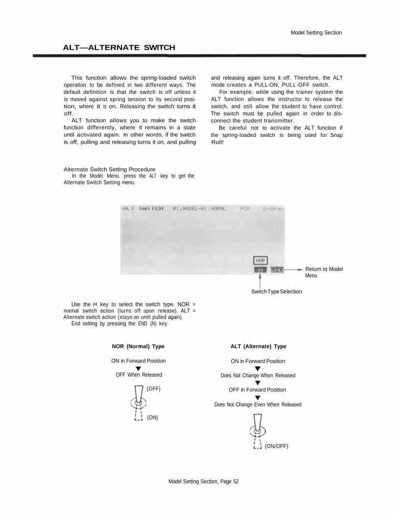
Model Setting Section
ALT—ALTERNATE SWITCH
This function allows the spring-loaded switchoperation to be defined in two different ways. Thedefault definition is that the switch is off unless itis moved against spring tension to its second posi-tion, where it is on. Releasing the switch turns itoff.
ALT function allows you to make the switchfunction differently, where it remains in a stateuntil activated again. In other words, if the switchis off, pulling and releasing turns it on, and pulling
and releasing again turns it off. Therefore, the ALTmode creates a PULL-ON, PULL-OFF switch.
For example, while using the trainer system theALT function allows the instructor to release theswitch, and still allow the student to have control.The switch must be pulled again in order to dis-connect the student transmitter.
Be careful not to activate the ALT function ifthe spring-loaded switch is being used for SnapRoll!
Alternate Switch Setting ProcedureIn the Model Menu. press the ALT key to get the
Alternate Switch Setting menu.
Return to ModelMenu
Switch Type Selection
Use the H key to select the switch type. NOR =normal switch action (turns off upon release), ALT =Alternate switch action (stays on until pulled again).
End setting by pressing the END (N) key.
NOR (Normal) Type ALT (Alternate) Type
ON in Forward Position
OFF When Released
ON in Forward Position
Does Not Change When Released
(OFF) OFF in Forward Position
Does Not Change Even When Released
(ON)
(ON/OFF)
Model Setting Section, Page 52

Model Setting Section
THR—THROTTLE CURVE
The Throttle Curve function applies only toAirplanes and Helicopters. Its purpose is to selectwhether the throttle curve function is to be usedwith the active model.
The throttle curve divides the full travel of thethrottle stick into twelve segments separated bythirteen points. The location of these points maybe set with the TCV key in the Condition menu.
Throttle Curve Activation ProcedureIn the Model Menu, press the THR key to get the
Throttle Curve Activation menu.
Throttle Curve ModeSetting Button-
Return to ModelMenu
Activate/Inhibit Keys
Use the ACT (F) key to activate the curve setting,and use the INH (G) key to deactivate the curve.
End setting by pressing the END ( M ) key.
Model Setting Section, Page 53

Model Setting Section
SWH—SWASHPLATE TYPE
This function is used to define which type of swashplate mixing is
to be used for the active helicopter model. The mixing functions
should be selected to match the swashplate on the model.
Swashplate Type Setting ProcedureS-1 TypeUse this type for helicopters with conventional linkages.
S-2 TypeUse S-2 mixing when the pushrods are positioned asshown in the figure. Elevator operates with a mechanicallinkage.With Aileron inputs, the aileron and pitch servos tilt the
swashplate left and right;with Pitch inputs, the aileron and pitch servos raise the
swashplate up and down.
S-4 TypeIf the servo inputs are located as shown, use S-4 Mixing.With Aileron inputs, the aileron and pitch servos tilt the
swashplate left and right;with Elevator inputs, the servos tilt the swashplate fore
and aft;with Pitch inputs, all four servos raise the swashplate up
and down.
SR-3 TypeIf the servo inputs match the figure, use SR-3 Mixing.With Aileron inputs, the aileron and pitch servos tilt the
swashplate left and right;with Elevator inputs, the three servos tilt the swashplate
fore and aft;with Pitch inputs, all three servos raise the swashplate up
and down.
SN-3 TypeUse SN-3 Mixing if the servo inputs match the figure.With Aileron inputs, the three servos tilt the swashplate
left and right;with Elevator inputs, the elevator and pitch servos tilt the
swashplate fore and aft;with Pitch inputs, all three servos raise the swashplate up
and down.
Use the reversing function (REV) as necessary to get theproper aileron, elevator, and pitch operations.
S-2 Type
SR-3 Type
SN-3 Type
Model Setting Section, Page 54
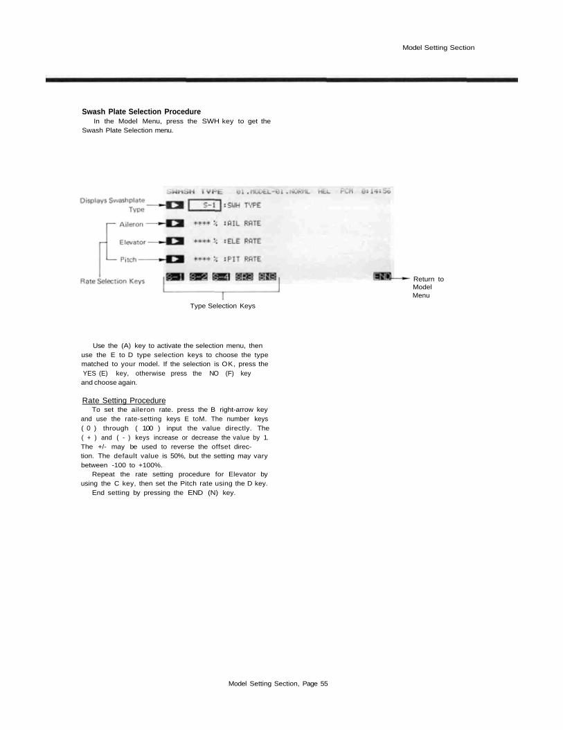
Model Setting Section
Swash Plate Selection ProcedureIn the Model Menu, press the SWH key to get the
Swash Plate Selection menu.
Return toModelMenu
Type Selection Keys
Use the (A) key to activate the selection menu, thenuse the E to D type selection keys to choose the typematched to your model. If the selection is OK, press theYES (E) key, otherwise press the NO (F) keyand choose again.
Rate Setting ProcedureTo set the aileron rate. press the B right-arrow key
and use the rate-setting keys E toM. The number keys( 0 ) through ( 100 ) input the value directly. The( + ) and ( - ) keys increase or decrease the value by 1.The +/- may be used to reverse the offset direc-tion. The default value is 50%, but the setting may varybetween -100 to +100%.
Repeat the rate setting procedure for Elevator byusing the C key, then set the Pitch rate using the D key.
End setting by pressing the END (N) key.
Model Setting Section, Page 55

Model Setting Section
RDR—ROTOR DIRECTION
This function is used to tell your PCM 1024Z properly set the mixing directions. The rotationsystem the rotor rotational direction, so it can direction, when viewed from the top, is entered.
Rotor Direction Setting ProcedureIn the Model Menu, press the RDR key to get the
Rotor Direction Setting menu.
Return to ModelMenu
Select Rotation Direction Keys
Use the CW ( F) key to select the clockwise (asviewed from above) rotation direction, and use the CCW(G) key to select the counter-clockwise direction. Thechosen direction appears in the display box.
End setting by pressing the END (N) key.
Model Setting Section, Page 56

Model Setting Section
INV—INVERTED PITCH
This function is used to activate inverted flight
functions for the model in active memory. This
function allows the inverted flight to use the
normal flight functions (the linkages must be
adjusted for inverted flight, however). The position
at which the normal-inverted low side pitches cross
("cross position") can be set. However, the invert-
ed flight high pitch/low pitch rate may be set with
the inverted pitch (INV) function available in the
Flight condition menu.
Inverted Pitch Setting ProcedureActivation of command
In the Model Menu, press the INV key to get theInverted Pitch Setting menu shown below.
Pitch Servo
Displays InvertedPitch Status
Press to ChangeCross Position
Press to Set theOn/Off Switch
Return to ModelMenu
Activate/Inhibit Keys
Use the ACT ( F ) key to activate the function, anduse the INH ( G ) key to deactivate it.Cross Position Setting
Press the B key to activate the Cross Position Settingmenu. The rate-setting keys F to M appear, and includethe number keys ( 0 ) through ( 50), which may be usedto input those values directly, and the ( + ) and ( - )keys used to increase or decrease the value by 1. Thedefault cross position is 30%, but the setting may varybetween 0 to 50%.
ON-OFF Switch SettingUse the SWT { P ) key to call up the switch-setting
menu. Switch F is the default switch, but the on directionis not set. Use this menu to set the switch and on direc-tion. For a description of the switch setting method,refer to page 37.
Exit the inverted pitch setting menu by pressing theEND (N)) key.
Model Setting Section, Page 57

Model Setting Section
PIT—PITCH CURVE
The Pitch Curve function applies only to Heli-copters. Its purpose is to select whether the pitchcurve function is to be used with the active model.
The pitch curve divides the full travel of thestick into twelve segments separated by thirteenpoints. The location of these points may be setwith the PCV key in the Condition menu.
Pitch Curve Activation ProcedureIn the Model Menu, press the PIT key to get the
Pitch Curve Activation menu.
Return to ModelMenu
Activate/Inhibit Keys
Pitch Curve ModeSetting Button
Use the ACT ( F ) key to activate the curve setting.and use the INH (G) key to deactivate the curve.
End setting by pressing the END (N) key.
Model Setting Section, Page 58

Common Condition Section
COMMON CONDITIONS SECTION
This section contains information on how to use the model condi-tions that are common to ALL types of models, including such asthrow volumes, dual rates, programmable mixes, subtrims, and condi-tion naming. This material should be used in conjunction with theCondition Settings sections for each type of aircraft, following this
section. (The helicopter condition menu is shown below for demon-stration purposes.)
These functions are found in all Model Menus (Airplane, Helicop-ter, and Sailplanes with 2, 4, and 5 wing servos), so rather than repeatthem in each model section, they are presented once in this section.
Select Line WithThese Keys
To Home Screen
To System Menu
-Condition Hold
To Model Menu
To Condition Menu
Function Selection Keys
Common Conditions Section ContentsItemATV
AFRD/R.
PMX
STM
TOF
CNA
TRM
Definition. . .Adjustable travel volume.
Channel delay . . . . . . .
. . .Adjustable function rate .
. . .Dual rate. . . . . . . . . .
. . .Programmable mixing
. . .Sub trim . . . . . . . . . .
. . .Trim offset. . . . . . . . .
. . .Condition naming. . . . .
. . .Digital trim . . . . . . . .
Function. . .Set maximum servo travel . . .
. .Use to slow changes betweendifferent trims
. . .Use to set exponential throws.
. . .Program switches to reduce . .control motion
. . .Use to correct unwanted. . . .tendencies during flight
. . .Set the neutral position of. . .each servo
. . .Use to set different trims for .different flight conditions
. . .Name each flight condition foreasy recognition
. . .Adjust the sensitivity of the . .electronic trims
Page60
. . .6264
65
68
. . . 69
. . . 70
71
Common Conditions Section, Page 59

Common Condition Section
ADJUSTABLE TRAVEL VOLUME (ATV)
The ATV function adjusts the servo left and
right throws, and to generate differential throws
and correct for linkages. The travel rate can be
varied from 1% to 140% in each direction on chan-
nels 1 to 8. Setting so that the servo travel exceeds
the set value even when the travel is increased by
mixing, etc., is also possible by setting the mixing
mode. NOTE: Stick movement is indicated by the
" " "symbol on the screen.
Included in this function is the servo delay
setting menu. This function is used to smoothly
transition between different servo neutral posi-
tions when the flight condition is changed.
Inputting Travel VolumesActivation of command
In the Condition Menu, press the ATV key to get theATV menu shown below.
Mode setting To next screen
Channel setting
Rate setting(Side A)
Rate setting(SideB)
Return to condition menuMode selection keys
Channel selectionTo enter the channel selection menu, press the B key,
and then press the key of the channel to be set. Depend-ing on the Model setup, the following keys will appear onthe bottom of the screen:
Airplane: AIL ELE THR RUD GEA FLP AU1 AU2Helicopter: AIL THR RUD GYR PIT AU1 AU2Sailplane: AIL ELE ABR RUD SF1 SF2 AU1 AU2
ATV Mode selectionTo select the ATV mode, press the
normal mode by pressing the NOR
key. Select thekey.
Input RatesYou can select the amount of travel in both directions,
which are designated as "A" and "B". To enter the ratefor Side A, press the C key and use the rate setting keysF to M to input your desired rate. The rate is initiallyset to 100%.
Press the numeric key nearest the rate you desire fromamong the H (0) to M (100) keys. You can thenincrease and decrease the selected value with the G ( - )and F ( + ) keys. Each key press adds or subtracts 1.Set the movement up so that no binding occurs at anyextreme motions of sticks, knobs, or sliders. You may setthe travel to anywhere between 10 and 140%.
Now you will set up Side B's rate similarly. Press theD key and set the rate with the rate setting keys F toM As before, use the numeric keys to get the travel youdesire.
Repeat this procedure for all the channels in sequence.When you are finished, end by pressing the END Nkey, or use the NXT R key to get to servo delayprogramming.
Common Conditions Section, Page 60

Common Condition Section
Programming Servo Delay at Condition Switching
This function is used to set the servo delay for eachchannel, from channel 1 to channel 8. Whenever a flightcondition is switched, the system uses the programmeddelay to slow down sudden servo position changes. This
might be used, for example, to prevent a sudden loss oflift on a sailplane when switching from flaps down forlaunch to a regular position for normal flight.
Inputting Channel DelaysThe setting screen for this function is called from the
ATV setting screen. If you are not already in the ATVmenu, select it from the condition menu. Next, press theNXT R key at the ATV setting screen. This actiondisplays the channel delay setting screen shown below.
Return toATV screen
Return tocondition menu
Channel selection keys
Select the desired channel with the F to M keys.When selected, input the delay with the numeric keys Fto M. The delay may be set independently for each chan-nel between 0 and 100%. Each 20% delay works out to beapproximately one second, but experiment to be surethat you get what you want.
Select the next channel with the SEL O key andrepeat these steps to input its delay.
When you are finished, you may return to the ATVmenu by pressing the PRE R key, or you may returnto the Model menu by pressing the N (END) key.
Afteroperation
Beforeoperation
Common Conditions Section, Page 61

Common Condition Section
ADJUSTABLE FUNCTION RATE (AFR)
This function is used to adjust the throw andoperation curve of the stick, lever, and switchfunctions (CH1 to CH8) for each flight condition.This is normally used after ATV has defined themaximum throw directions (ATV acts on ALLflight condition settings). When mixing is appliedfrom one channel to another channel, both chan-nels can be adjusted at the same time by adjustingthe operation rate by AFR function.
In the AFR mode, the function operation ratecan be adjusted for each travel direction. Theservo's response curve can be changed so that thecontrol can be performed comfortably by settingthe EXP1/EXP2 modes. This is best understood byexamining the curves that the PCM 1024Z systemdisplays as the parameters are changed. The AFRfunction may be programmed to have a rate varia-tion from 0 to 140%; the EXP1/EXP2 curve ratecan be adjusted from -100 to +100%. With 0%,
exponential produces a normal straight-lineresponse.
In the EXP1 mode, the servo movement nearthe neutral position can be made sensitive or in-sensitive. EXP2 mode is applicable to throttle andother control sliders and levers that do not self-center, and changes the response shape at one endof the control movement. The response rate can bemade steep or gradual. NOTE: if you activate thethrottle curve and pitch curve functions, the throt-tle channel and pitch channel EXP curves areoverridden.
If the LIN mode is defined within the EXP1mode, you can make an ordinary rotary servo havesimilar motion to that of a linear servo. In otherwords, the rotary servo moves more the further itis away from neutral, to simulate a linear output,which moves the same amount regardless of servoposition.
Adjusting Function RatesActivation of command
In the Condition Menu, press the AFR key to get theAFR menu shown below.
Mode setting
Channel Setting
Rate setting(Side A)Rate setting(Side B)
Return to condition menuTo next screen
Channel SelectionTo enter the channel selection menu, press the B key.
and then press the key of the channel you wish to set.Depending on the Model setup, the following keys willappear on the bottom of the screen:
Airp lane :Helicopter:Sailplane:
Input RatesYou can select the rates in both directions, which are
designated as "A" and "B". To enter the rate for Side A,press the C key and use the rate setting keys F to El toinput your desired rate. The rate is initially set to 100%.
Press the numeric key nearest the rate you desire fromamong the H (0) to M (100) keys. You can thenincrease and decrease the selected value with the F(+)and G (-) keys. Each key press adds or subtracts 1.Set the movement up so that no binding occurs at anyextreme motions of sticks, knobs, or sliders. You may setthe travel to anywhere between 10 and 140%.
Now you will set up Side B's rate similarly. Press theD key and set the rate with the rate setting keys F toM. As before, use the numeric keys to get the travel youdesire.
Repeat this procedure for all the channels in sequence.
Common Conditions Section, Page 62

Common Condition Section
Mode selection Linear Mode MixingPress the Mode Selection A key. then press the NXT To set the linear mode, do the following: press the A
L key to get to the mode setting menu. To choose the key, then press the LIN H key. This automaticallyEXP1 mode, press the EX1 I key. If you want the sets the side A and side B rate curves to —16%, to ap-EXP2 mode, press the EX2 J key. proximate linear response.
Side A curve rate setting EndingSet the rate as described earlier. If you need to change Press the
the polarity of the exponential response, use the +/- menu.F key
Side L rate settingSet the rate as described earlier. Note this setting is
not available for EXP2 mixing.
END N key to exit to the Condition
Common Conditions Section, Page 63

Common Condition Section
DUAL RATES AND EXP CURVE SWITCHING
Programming this function allows you to
change the function operation rate and operation
curve for any three channels by moving a switch.
You may add switchable exponential response to a
function without using the AFR menu. The switch
position and ON/OFF direction can be chosen, or
you may link ON/OFF control with the position
of a control stick, such as throttle.
If you want to change the response rate around
stick neutral, you can use the EXP1 mode, and
make the servo movement sensitive or insensitive
(0% exponential produces a normal straight-line
response). For positionable controls like throttle,
the EXP2 mode may be used to control the rise of
the curve, either steep or gradual as the stick is
moved. A special linear mode uses a particular
value of the EXP1 curve to simulate operation of a
linear servo with an ordinary rotary servo.
Initially, the three separate Dual rate circuits
are set as follows: D/R A: Aileron; D/R B: Eleva-
tor; D/R C: Rudder. Of course you may change
these to control any function.
NOTE: If the throttle curve and pitch curve
functions are activated, the throttle channel and
pitch channel EXP curves are cleared.
Mode setting
ChannelSetting
Rate Setting(Side A)
Rate Setting(Side B)
Trim Rate setting
Mode selection To Next Screen
SwitchSetting
Return to D/R Ato C SelectionMenu
Setting Up Dual Rates and Curve SwitchingActivation of command
In the Condition Menu, press the D\R key to get tothe A to C Dual Rate circuit selection screens (notshown). Choose the desired Dual Rate circuit with theAto C keys, to get the D/R menu shown below (the 'A'menu is shown).
Dual Rate Control SelectionTo select the control to be used in the Dual Rate func-
tion, press the B key, then press the key of the channelto be set with the E to L keys. Initially, Circuit A is setfor Aileron. Depending on the Model setup, the followingkeys will appear on the bottom of the screen:
Airplane:Helicopter:Sailplane:
Activate the Dual RatePress the A key to get to the activation keys. Select
the D/R mode by pressing the ACT F key, or deacti-vate the function by pressing the INH G key.
Setting The Dual RatesPress the C key, and set the side A rate with the rate
setting keys F to M . Use the numeric key closest to the
value you'd like to set, then press the + and - keys ( F
and G ) to increase and decrease the selected value.For the side B rate, press the D key and set as done
for Side A.To use the exponential curve in dual rates, press the
A key, then press the NXT L key.Press the EX1 I key to activate the EXP1 mode,
or press the EX2 L key to activate the EXP2 mode.Set the Side A and Side L rates as described previously.
To choose linear response mode, press the A key,then press the NXT L key. Select the INH H key tochoose the linear mode. The A and B rate curve settingsare automatically made.
D/R switch selection and ON/OFF settingCall the switch setting screen by pressing the SWT
O key. For a description of the switch setting method,see page 40. If you'd l ike the dual rates to be turned onautomatically by stick position, press the STK O but-ton while in the switch selection screen. For example,you could have dual rates turned on when the throttlestick passed a defined position.
Dual Rate circuits B and C are set the same way as forCircuit A.
To Exit, press the END N key. This returns you tothe D/R A-to-C selection screen. Press the END N keyagain to return to the Condition Menu.
Common Conditions Section, Page 64

Common Condition Section
PROGRAMMABLE MIXING (PMX)
Programmable mixing may be used to correctundesired tendencies of the aircraft, and may beused for unusual control configurations. Mixingmeans that the motion of a command channel,called the "master," is added to the motion of themixed channel, called "slave." For example,Aileron-to-Rudder mixing applies the aileronmotion to the rudder servo as well as the com-manded rudder position. You may even set upmixing so that the mixing rate can be changedaccording to the position of a channel other thanthe mixing channel ("Rate Control"), for examplethrottle position.
The midpoint of the mixing curve (mixing rate= 0 point) can be freely set. You may choose tohave the Master trim rate added to the Slave chan-nel response, or not ("TRIM" setting). The mixingrate can also be input as a seven-point curve. Youmay define Mixing ON/OFF switches or you maychoose to have mixing remaining on all the time.
Any two channels can be mixed in each of thefive available mixing circuits. Each mix circuitmay use one of three mixing types. For Linear-type mixing, the mixing rate is proportional to themaster channel motion. Offset-type mixing appliesa fixed offset or preset to the programmed channelservo operation, and strictly speaking, is not reallymixing at all. Hovering-type mixing applies anoffset to the neutral point of the slave function.
Your PCM 1024Z system includes a powerfulLink function, which allows Programmable mixingto be linked with the special mixing functionsin the Flight Condition menus, or with otherprogrammable mixing functions.
The Master channel MIX mode may be selected,where the master channel AFR and D/R settingsare observed, or the UNMIX mode can be used. Inthe UNMIX mode, the motion of the master con-trol is utilized without regard to the AFR and D/Rsettings.
SCREEN 1
Mix Circuit No.
Master Channel- Slave Channel
SCREEN 2
ACT/INH mode
Master Channel
Slave Channel
Mixing type
SCREENSACT/INH Selection Keys
Mixing ON/OFFState
Current setting
To condition menu
Trim ON/OFF
Master channelMIX mode
Mixing SwitchMenu
Return topreceding screen
Linear type
Return topreceding screen
Mixing Number Selection Keys
Common Conditions Section, Page 65

Common Condition Section
Programming the Mixers
Activation of commandIn the Condition Menu, press the PMX key to get the
PROG MIX menu shown as Screen 1 in the top of theillustration below.
Selection and Activation of Mixing Menu (Nos. 1 to 5)Press the number key associated with the mixing menu
that you wish to program with the 1 to 5 ( F to H )keys. Press the A key (moves to Screen 2 display shownbelow), then activate the mixer by pressing the ACT—Fkey. You may inhibit the mixer by pressing the INHGkey.
Choosing the Mixing TypePress the D key to get to the mix type selection
menus. Now, you may select the Linear type by pressingthe LIN E key, select the hovering type by pressingthe HOV G key, select the 7-point curve type bypressing the CRV H key, or select the Rate Controltype by pressing the CTL I key.
Master channel setting (not for offset and hovering typemixing)
To select the control to be used as the Master channel,press the B key. then press the key of the channel to beset with the E to L keys. Depending on the Modelsetup, the following keys will appear on the bottom ofthe screen:
Airplane:Helicopter:Sailplane:
Mixing ON/OFF switch selection and ON/OFF directionsetting
When a mixer is first activated, an ON/OFF switch isnot defined. If you wish to define an on/off switch tocontrol the mixing, call the switch setting screen bypressing the SWT P key. For a description of theswitch setting method, see page 37.
Mixing Rate InputtingTo input the mixing rate, call the rate setting screen
by pressing the NXT O key. This action calls up themenus shown in the figure as Screen 3.
If the linear type of mixing is selected, you may offsetthe Mixing switching point setting by pressing the B key.then setting the master control to the desired switchingpoint, and pressing the SET F key.
Mixing Rate Setting, Sides A and FTo input the numerical mixing values for the A side of
Linear mixing, press the C key. You may then set therate with the numeric setting keys E to M. The mixingrate is initially set to a value of +50%, but may be setanywhere in the range between —100 to +100%. Notethat on the setting screen graph, the top is — and thebottom is+.
You may now set the values for Side B mixing as sideA was done above.
If Offset mixing is selected, you may set the offsetwith the rate setting keys E to M The initial offsetvalue is 0%, but you may set this anywhere between —100and +100% with the numeric keys.
If you will be linking this mixer with other mixers,press the LNK M key. Linking is turned on and offalternately each time the key is pressed. When linking isON, a "-»" is displayed in front of the Master channelname.
Slave channel settingTo select the Slave channel, press the C key and
select the desired channel with the E to M keys. To linkthe Slave channel with other mixing, press the LNK Mkey. A "-»" is displayed after the channel name.
Trim ON/OFF SettingTrim ON/OFF only applies to Linear type mixing. To
select Trim ON/OFF, press the R key. To add the mastertrim operating rate to mixing, press the ACT F key. Ifyou do not wish to add trim operating rate to mixing, usethe INH G key.
Master Channel MIX Mode DefinitionThis definition does not apply to offset-type and
hovering-type mixing. To define the Master channel mixmode, press the Q key. If you wish to add AFR, D/R,and curve set rate to mixing, press the MIX F key, ifyou do not wish to add AFR, D/R, and curve set rate tomixing, press the G (UN) key.
SERVORESPONSE
OFFSET RANGE
OFFSET RATE
STICK MOTION
If Hovering mixing is selected, you input the Slavechannel neutral position offset range setting using the Ckey, and set the offset range with the rate setting keys Fto M . This value is initially set 5to 100%, but can varyanywhere between 0 and 100%.
Now you will set Slave channel neutral width setting.To do this, press the D key and set the offset with therate setting keys E to M. This value is initially set to0%, but can vary anywhere between 0 and 100%.
Common Conditions Section, Page 66

Common Condition Section
For the 7-Point Curve mixing method, each of thepoints on the curve must be defined. To set the points,first select the point with movement keys Q and R. ThePT-> key increases the point number by one (moves oneto the right), and the <-PT reduces the point number byone (moves one to the left). Once you have selected thepoint on the curve you wish to set, input the rate with thenumeric setting keys E to M.
For the Rate Control Type of mixing, you need tospecify the control channel (this is not the master or slavechannel). Press the A key and select the desired channelwith the channel keys E to L . You will then need toinput the Mixing rate setting at the seven points. Press theB key and select the point with the movement keys Qand R. then input the rate with the numeric keys.
Rate control mixing has some interesting applications.For example, in a sailplane model you might want toadjust the rate of aileron-rudder coupling depending onthe amount of wing camber — the more camber, theslower the model is flying, and the more rudder mixing isneeded. For this function, you could link the ruddercoupling mixer in the Special mix menu to a PMIX mixer,
with the rate control specified by the slider control thatcontrols the camber. Note that if you have differential setup, you will not get equal coupling to either side, UN-LESS you turn the master mix mode to UNMIX, so thatthe differential is ignored for the mixing.The PMIX menus on the PCM 1024Z are extremelypowerful, and we would recommend that you experimentwith all the different mixing types in the menus. Just setup a receiver and some servos, and try different mixingcurves, types of mixing, offsets, linking, and all the otherparameters. This is a simple way to understand how themixing functions work, and after trying out a few ofthem, you will discover that programming the mixers iseasier than trying to read these instructions!
EndingHad enough? Before you leave, try different stick
motions to be sure that the mixing functions that youhave defined behave as you expect them to. When you aresatisfied, press the END N to return to Screen 2. If theN key is pressed again, you will return to Screen 1 If Nis pressed again, the display returns to the Conditionmenu.
MIXING LINKING METHODS
Common Conditions Section, Page 67
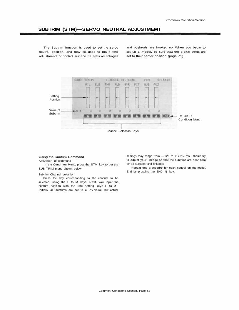
Common Condition Section
SUBTRIM (STM)—SERVO NEUTRAL ADJUSTMEMT
The Subtrim function is used to set the servo
neutral position, and may be used to make fine
adjustments of control surface neutrals as linkages
and pushrods are hooked up. When you begin to
set up a model, be sure that the digital trims are
set to their center position (page 71).
Value ofSubtrim
Return ToCondition Menu
SettingPosition
Channel Selection Keys
Using the Subtrim CommandActivation of command
In the Condition Menu, press the STM key to get the
SUB TRIM menu shown below.
Subtrim Channel selectionPress the key corresponding to the channel to be
selected, using the F to M keys. Next, you input thesubtrim position with the rate setting keys E to MInitially all subtrims are set to a 0% value, but actual
settings may range from —120 to +120%. You should tryto adjust your linkage so that the subtrims are near zerofor all surfaces and linkages.
Repeat this procedure for each control on the model.End by pressing the END N key.
Common Conditions Section, Page 68

Common Condition Section
TRIM OFFSET (TOF)
The Trim Offset function may be used to set a
trim offset for different flight conditions. For
Helicopters, this is very useful to set offsets when
the Pitch -> rudder (P->R) mixing is used. For Sail-
planes, it may be used for setting trims for both
elevator (ETM) and full wing camber, which may
be programmed within Trim mixes 1 and 2 (TM1,
TM2).
You may set a time delay to slow down the
servo motions when the flight condition is switch-
ed. The delay should be entered in the digital trim
TRM function (page 71).
Mode Setting
Trim Offset Value
Trim SelectionKeys
Return ToCondition Menu
Mode Selection Keys
Using the Trim Offset CommandActivation of command
In the Condition Menu, press the •TOF key to get theTRM OFFSET menu shown below.
Press the A key to get the activation menu. You mayactivate the Trim Offset function by pressing the ACTF key; to deactivate the function, press the INH Gkey.
Trim Position Selection (T1 to T4)Select the trim to be set with the O to R keys. The
displayed trims T1 to T4 are the channels set by the func-tion change (FNC) menu. Initially, the display should
show T1 (trim 1): Aileron; T2 (trim 2): Throttle; T3(trim 3): Elevator; T4 (trim 4); Rudder. Note that when atrim is set to ATL type (throttle, for example), the offsetrate cannot be set.
Offset Rate settingSet the trim offset with the rate setting keys EtoM .
Initial values are set to 0%, but may range between —100and +100%. Repeat these steps for each trim.
End setting by pressing the END N key.
Common Conditions Section, Page 69

Common Condition Section
CONDITION NAME REGISTRATION (CNA)
This function may be used to name the active
flight condition, and can be a maximum of five
characters long. Once entered, the active condition
name is displayed after the model name at the top
center of the screen.
We recommend that you register a name that is
easy to remember for easy confirmation of the
active flight condition.
Registering a Condition NameTo register the desired Condition Name, press the
CNA key from the Condition Menu to enter the namingfunction as shown below.
Condition Name
Cursor
Use to Select Character in Line
Choose DesiredCharacter
Desired CharacterLine Selection
Return toCondition Menu
Use To Input Desired Character Select Character Location Keys
Press the A arrow key to select the registration func-tion. If necessary, move the cursor to the desired locationwithin the Condition Name with the G and I keys (left-and right-arrow).
Select the line containing the desired character withthe O to R keys. Now. use the K and M keys to moveacross the line until the cursor is underneath the desiredcharacter. To enter the character into the Condition Nameline, press the ENT H key. Repeat this procedure forthe remaining characters of the desired name. To makecorrections to entered characters, use the G and I keysto move to the character to be changed, and enter a newone.
When the name entry is completed, press the END N key.
Common Conditions Section, Page 70

Common Condition Section
DIGITAL TRIM (TRM)
The Digital Trim function may be used toprogram how the trims change as the force changeson the trim tab switches. When you press lightlyon the trim you get one speed of operation, andwhen you increase the pressure, the repetitionspeed and rate also increase. The repetition speedand step rate and can be adjusted to match eachmodel, and the beeping sound that occurs when atrim is operated can be turned on or off.
Any time you use the model select (MSL) func-tion to choose another model, the new modelcomes with its own trim data, and the previoustrim data are stored with the previous model.When a model is retrieved, its trim positions arealso recalled.
There are two Trim modes available. The
Normal mode is suitable for centering controlssuch as the transmitter sticks, and trimming isperformed at the neutral position. The ATL modeis usually used for throttle, where trimming isperformed only at the low end.
The trim functions on your PCM 1024Z havetwo operational modes. The Separate mode trimseach flight condition separately, and has no effecton the trim of other conditions. The Combinationmode should be used when you want to link thetrim operation between modes. When a trim posi-tion is changed, it changes for ALL flight condi-tions.
The Digital Trim function is also used to set thedelay for trim offsets when switching betweendifferent flight conditions.
Using the Digital Trim MenuActivation of command
In the Condition Menu, press the TRM key to get theTRIM menu shown below.
Trim MemoryPosition
Current TrimPosition
Stores Current Trims In Memory
Recalls TrimMemoryTrim Setting Screen Call Buttons
Return ToCondition Menu
Trim StorageTo store the current trim positions in memory, press
the C->M K key and press the YES I key. This willover write the previous positions. If you DO NOT wish tomemorize the trim positions, press the NO K key.
Recall Trim Memory
Trim settingTo set the trim switch parameters, call the trim to be
set with the trim keys E to H . This will bring up theTrim setting screen as shown below.
Press the M->C L key, then the YES I key, torecall the memorized trim position (this will wipe outyour current trim settings). If you do not wish to over-write the trim state, press the NO J key.)
Common Conditions Section, Page 71

Common Condition Section
Screen 2
Trim ModeSetting
Delay-RateSetting
Value ofSubtrim
SteppingRateRepetitionSpeed
SteppingRate
RepetitionSpeed
Return ToCondition Menu
FirstStep
SecondStep
Mode Selection Keys
Trim Mode SelectionTo select the trim mode, first press the A key. You
may select the normal mode by pressing the NOR EKey, or select the ATL mode by pressing the ALT Fkey.
Combined/Separate Mode SelectionSelect the Combination mode (trim controls all flight
conditions) by pressing the CMB H key, or select theSeparate mode (trim only controls current flight condi-tion) by pressing the SEP I key.
Delay settingTo set the delay for trim changing, press the B key
and set the delay with the rate setting keys F to M . Theinitial delay value is 0%, but the setting may vary from 0to 100%.
Trim Notification BeeperPress the C key to activate the beeper control, then
turn on the beeper by pressing the ON F key. Youmay turn off the beeper by pressing the OFF G key.
First Step Rate and Repetition SpeedTo set the first step parameters, press the R key. Now
you may set the step rate with the rate setting keys E toM. The initial value is 3. but your value may vary from1 to 50 or left unchanged by using INH.
Now set the repetition speed by pressing the Q key.The repetition speed may now be set with the rate settingkeys F to M . This is initially set to 60%, but may varyfrom 0 to 100%.
Second Step Rate and Repetition SpeedThe second step rate is reached when further pressure
is held on the trim switches. To set the second step para-meters, press the P key. Now you may set the step ratewith the rate setting keys E to M The initial value is 8.but your value may vary from 1 to 50 or left unchangedby using INH.
Now set the repetition speed by pressing the O key.The repetition speed may now be set with the rate settingkeys F to [M . This is initially set to 80%, but may varyfrom 0 to 100%.
ReturningPress the END N key to return to Screen 1. Press
the N key again; the display returns to the conditionmenu.
Common Conditions Section, Page 72

Airplane Section
AIRPLANE SECTION
This section contains information on the commands that apply to
powered aircraft only. Each of these functions can be set independ-
ently for different flight conditions.
For conditions that apply to all models (ATV, AFR, D/R, PMX,
STM, TOF, CNA, and TRM functions), refer to the Common Condi-
tions section. For instructions on Helicopters and Sailplanes, refer to
the sections pertaining to those aircraft.
To get to these settings, press the MDL key from any menu in an
Airplane setup. To select one, first select the line containing the
desired function with the B, C, or D keys. Then use the F toL
keys to select the function to be entered.
Select DesiredLine WithThese Keys
To Home Screen
To System Menu
To Model Menu
Function Selection Keys Activates Condition Hold Function
Airplane Section Table of ContentsAirplane Transmitter Controls and Functions. . . . . . . . . . . . . . . . . . 74Airplane Receiver and Servo Connections . . . . . . . . . . . . . . . . . . . . 76Pattern Airplane Setup Example . . . . . . . . . . . . . . . . . . . . . . . . .77Specific Control Setup DefinitionsADF . . .Aileron Differential. . . . . . .Sets more up than down . . . . . . . .80
travelA->R . . .Aileron - > Rudder. . . . . . . .Makes coordinated turns. . . . . . . 81VTL . . .V-Tail. . . . . . . . . . . . . . .Mixes rudder and elevator . . . . . . 82
into V-tailR->A . . .Rudder -> Aileron. . . . . . . .Correct drifts during knife-edge . . 83EVN . . .Elevon . . . . . . . . . . . . . . .Use for delta wings and tailless . . 84E->F . . .Elevator -> Flap . . . . . . . . .Make better high-lift maneuvers. . 85F->E . . .Flap-> Elevator. . . . . . . . .Correct for trim change with . . . 86
flapsCPT. . . .Collective Pitch . . . . . . . . .For consistent model speed in. . . 87
verticalsALV . . .Ailevator. . . . . . . . . . . . .Two elevator servos also do . . . . 88
aileronsFPN. . . .Flaperon . . . . . . . . . . . . .Two ailerons also act together. . . 89ABK . . .Airbrake. . . . . . . . . . . . .Make landings more predictable. . 91SNP. . . .Snap Roll . . . . . . . . . . . .Set preset control positions . . . . 93TCV . . .Throttle Curve. . . . . . . . . .Adjust throw to match . . . . . . . 94
geometry
Airplane Section, Page 73

Airplane Section
AlRPLANE CONTROLS AND FUNCTIONS
Functions and locations given in this drawing are
the factory default positions, which occur upon
startup. Each setting can be easily changed as the
owner desires. The Function Change menu [FNC]
may be used for this purpose.
Carrying Handle6. Flap knob/Flap Trimmer16. Snap Roll/Trainer Switch
(ON in forward position,sprang to OFF) . . . (MODE
15. Landing Gear Switch ——(CH5)ON in forwardposition) . . . (MODE II)Collective Pitch/AirbrakeMixing Switch(ON in forwardposition) . . . (MODE I)
13. Elevator Dual Rate-Switch (ON in lowerposition)
14. Rudder Dual Rate—Switch and CH9 (ONin lower position)
9. Collective Pitch MixingIdle-up Lever
Tachometer SensorElevator TrimRudder Trim
2. Throttle.. . (MODE II)Elevator. . . (MODE I)
CAMPac Memory Module-Antenna.7. Spoiler (Ch. 7) knob10. Elevator-Flap Mixing
Switch (ON inupper position)
11. Snap Roll/TrainerSwitch (ON inforward position,sprung to OFF) ...(MODE I)
5. Collective Pitch/AirbrakeMixing (ON in forwardposition) . . . (MODE II)
Landing Gear Switch (CH5).ON in forward position . . .(MODE I)
8. CH8/Collective PitchMixing
12. Aileron Dual RateSwitch (ON in lowerposition)
Power-On Monitor Lamp
Stick Slant AngleAdjustment Screw
Throttle Trim
Aileron Trim
Neckstrap Hook
Large Liquid-Crystal Display
-Snap Roll DirectionSwitches (T9ZAPTransmitter only)
Rubber Grip Pad
(remove for sticktensionadjustment)
RF Module
System PowerSwitch Soft Keys
B. Elevator. . . (MODE II)Throttle.. . (MODE I)
1. Aileron
Data TransferTrainer CordDSC/Voltagemeasurement
Socket(with dustcap)
4. Rudder
Battery Cover Battery Change Jack (with dust cap)
Airplane Section, Page 74
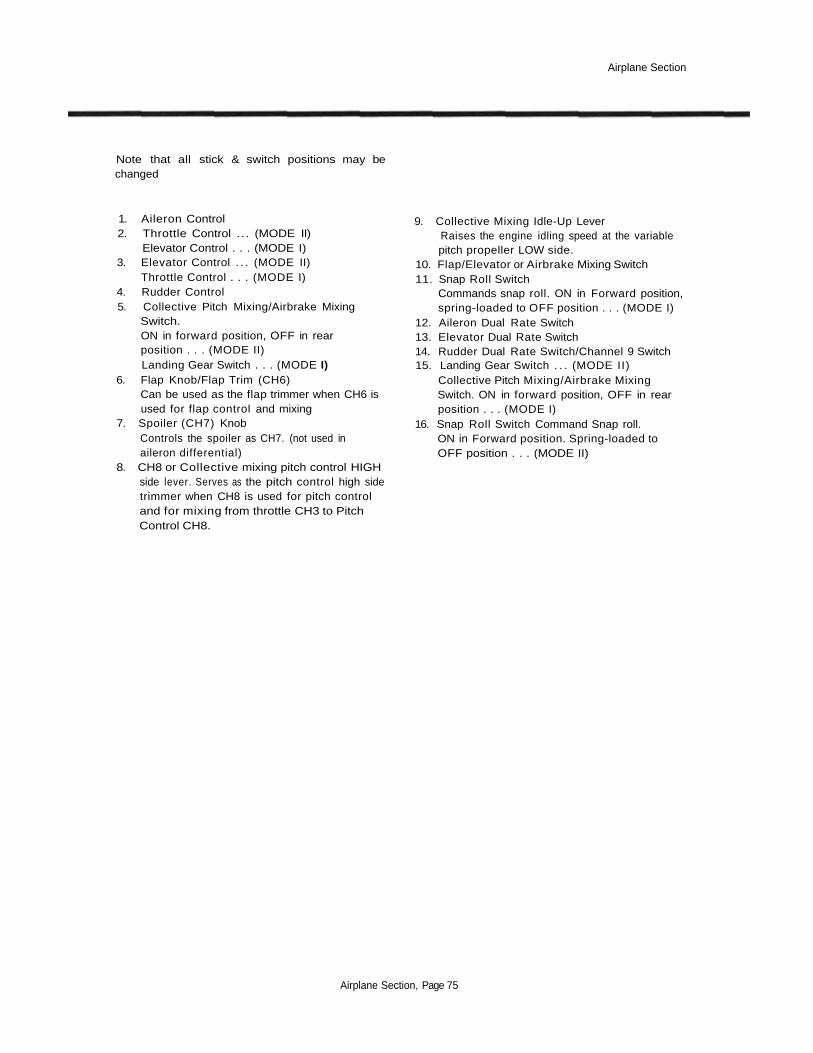
Airplane Section
Note that all stick & switch positions may bechanged
1. Aileron Control2. Throttle Control . . . (MODE II)
Elevator Control . . . (MODE I)3. Elevator Control . . . (MODE II)
Throttle Control . . . (MODE I)4. Rudder Control5. Collective Pitch Mixing/Airbrake Mixing
Switch.ON in forward position, OFF in rearposition . . . (MODE II)Landing Gear Switch . . . (MODE I)
6. Flap Knob/Flap Trim (CH6)Can be used as the flap trimmer when CH6 isused for flap control and mixing
7. Spoiler (CH7) KnobControls the spoiler as CH7. (not used inaileron differential)
8. CH8 or Collective mixing pitch control HIGHside lever. Serves as the pitch control high sidetrimmer when CH8 is used for pitch controland for mixing from throttle CH3 to PitchControl CH8.
9. Collective Mixing Idle-Up LeverRaises the engine idling speed at the variablepitch propeller LOW side.
10. Flap/Elevator or Airbrake Mixing Switch11. Snap Roll Switch
Commands snap roll. ON in Forward position,spring-loaded to OFF position . . . (MODE I)
12. Aileron Dual Rate Switch13. Elevator Dual Rate Switch14. Rudder Dual Rate Switch/Channel 9 Switch15. Landing Gear Switch . . . (MODE II)
Collective Pitch Mixing/Airbrake MixingSwitch. ON in forward position, OFF in rearposition . . . (MODE I)
16. Snap Roll Switch Command Snap roll.ON in Forward position. Spring-loaded toOFF position . . . (MODE II)
Airplane Section, Page 75

Airplane Section
AIRPLANE RECEIVER AND SERVO CONNECTIONS
The receiver output order is shown below:1. AIL Aileron (Ail 1 if FPN or ADF on. Elevon
1 if EVN on)2. ELE Elevator (V-Tail 1 if VTL on, Elevon 2
if EVN on)3. THR Throttle4. RUD Rudder (V-Tail 2 if VTL on)5. GEA Landing Gear (Elev 2 if ALV on)6. FLP Flap (Ail 2 if FPN activated)7. AU1 Spoiler (Ail 2 if ADF is used)8. AU2 Collective Pitch9. CH9 Channel 9
Be sure to insertproper direction
Airplane Section, Page 76