Embed Size (px)
Citation preview

GETTING TO KNOW THE 9Z:
by:Futaba Service Center
Service and Support Team
SOME OF THE MOST COMMON QUESTIONS AND ANSWERSON USING THIS POWERFUL RADIO SYSTEM.
9Z WC2 9-Channel System

This booklet is intended to be a user’s guide to help you get to know some of the many powerfulfeatures of the 9Z. It is a supplement to the very detailed instruction manual, and is not meant toreplace it in any manner. Rather it is intended to provide some in-depth explanations and detailedexamples to answer questions you may have about using your new radio.
Note that each example and glossary item includes keystroke-by-keystroke instructions of how toset up each feature. Every example assumes you have started from a totally blank model memory, andevery command group includes closing the feature back to the home menu and starting from the homemenu to start the next feature. This is done so that you can quickly and easily access one featurediscussed in an example without using all features discussed in that example. You do not need toclose and reopen every menu every time you use a feature. This is simply done for consistency. Everystep assumes you are starting from the home menu unless it is a continuation of programming afeature from the step before it.
Similarly, each example will have 3 columns: the first explains what the programming is going todo; the second explains the process, and the third is the actual keystrokes of how. By reading throughall 3 columns with each example you will become more familiar with the radio’s layout andprogramming. It may take some time, so be patient, but the end result is well worth it!
Updates and Additions? Please visit www.futaba-rc.com. As corrections and additions are made,new pages will be available here.
Additional questions? We hope you find this guide helpful in getting to know your 9Z. Havesuggestions for future additions, or other questions? Please visit our Frequently Asked Questions areaat www.futaba-rc.com/faq to see if your question may have already been answered. If not, thenfollow the “contact us” information area to contact our support team directly as listed below.
Need to send your 9Z for service? Please ship your radio (including the module, receiver, servos,battery, switches, and any other installed electronic equipment, especially following a crash or if askingus to diagnose an unknown problem) to:
Please be sure to provide us a detailed explanation of your concerns and service required, aswell as at least 2 means of daytime contact: phone, fax, or email are great, as well as your returnmailing address. If this is non-warranty service, please also provide a means of payment (Visa,Mastercard). Please note that upon request we will contact you with an estimate prior to performingANY repairs to a non-warranty item, so be sure to provide an easy way to reach you to avoid delays.
ADDRESS: Questions for Service? Questions for Support?Futaba Service Center phone: 217-398-0007 217-398-3630 x41610 Interstate Drive fax 217-398-7721 217-398-7721Champaign, IL 61822 email: [email protected] email: [email protected]

TABLE OF CONTENTS
I. Equipment Selection. Answering Common Questions
A. Channels/Frequencies and Frequency BandsB. Modules/Receivers/Accessories and Synthesized EquipmentC. Modulation, FailSafe and Resolution (512 vs 1024)D. Batteries: Charging and CyclingE. Training Equipment and Functions
II. Programming Specifics
A. Selecting the Correct Model Type 2-1B. Understanding Servo Travel vs. Function Travel (Multiple Rates) 2-2C. Multiple Servos for One Control Type and Other Set-up Options 2-4D. P-Mix Features 2-8E. Understanding the Basics of Conditions 2-10F. Specific Programming Examples 2-12
III. Glossary of Terms, Keystroke Commands, and Primary Manual Page References
1-11-31-61-91-10

CHAPTER I. EQUIPMENT SELECTION
A. Channels/Frequencies and Frequency Bands
How do I change the frequency of my transmitter?
Using a single-frequency module: To change the frequency when using a TK-FM non-synthesizedmodule, with the transmitter off, remove the module and replace it with a module on the desiredchannel. (Note that you can even change transmitter “bands”, for example from 72mHz to 50mHz.)All radio frequency circuitry is in the module so there is no need to “retune” after a module change.
Using a synthesized module: To change the frequency when using a TK-FSS synthesized module, firstfollow your flying site’s procedures to have exclusive use of your desired channel, then turn thetransmitter on while holding down the A or R key (so the radio does not transmit on its currentchannel.) Notice the “ON AIR” message normally under Futaba is replaced with “Radio ControlSystems”. The 9Z is not transmitting and will not transmit again until you turn the power off andback on.
How do I change the frequency of my receiver?
Using a single-frequency receiver: When using a non-synthesized receiver on 72mHz, the channel canUSUALLY be changed within certain groupings without requiring retuning of the receiver. AnyFutaba receiver purchased on 11-35 (“low band”), can be used on any other channel within that bandby changing crystals and properly range checking the radio system. Any Futaba receiver purchasedon 36-60 (“high band”) can similarly have a crystal change. Always fully range check your radioequipment after a crystal change, and if identical or improved range is not verified, DO NOT FLY.Send the transmitter and receiver to the Futaba service center for testing and tuning.
Using a synthesized receiver: To set the frequency on the R309DPS synthesized receiver, unplug thereceiver battery. Open the receiver’s dust cover. Adjust the left switch for the first digit of the desiredchannel and the right switch for the last digit of the desired channel. Close the dust cover. Plug in thereceiver battery. For more information see p.36 of the manual.
Can I use my 9Z on a different frequency BAND than it currently uses? Can I go to 75mHz forground use for Battlebots®, boats or cars? If I have a HAM license, can I use the radio on 50mHz?
The real plus of using a modular radio is that you can purchase a module and receiver on anyfrequency for the band legal for your intended use and use it safely and without any loss ofperformance. For example, you can purchase the TK modules on 50mHz, and we can convert TKmodules and most receivers to 75mHz. Please contact the Futaba Service Center for furtherinformation.
Desired Result Process Keystrokes
Turn On Without Transmitting Hold A or R during power onOpen Frequency (FRQ) Q C ISelect the Desired Frequency (use R & Q to page through)Use Set to Confirm and Close O N RCycle the Transmitter N R (power off, power on)
Power up without transmitting,then select the desiredfrequency and cycle thetransmitter to transmit on thenew frequency.
1-1

I fly on channel xx. A quarter wave antenna for that frequency would be xx", not the 9Z antenna’sfull length. Would I be better off using that transmitter antenna length instead of it fully extended?
Each Futaba transmitter has been tuned so that it will get the maximum output with the antennaprovided. The FCC certification was made with that antenna. The tuning circuitry in the transmittermakes allowances for any differences in the actual length of the transmitter antenna, and thetheoretical ideal length. You should fly your models with the transmitter antenna fully extended. Ifyou shorten it, you will suffer a considerable decrease in range.
1-2
50 MHz 72 MHz Low Band 72 MHz High BandCh. Freq. Ch. Freq. Ch. Freq. Ch. Freq. Ch. Freq.
00 50.80001 50.82002 50.84003 50.86004 50.88005 50.90006 50.92007 50.94008 50.96009 50.980
11 72.01012 72.03013 72.05014 72.07015 72.09016 72.11017 72.13018 72.15019 72.17020 72.19021 72.21022 72.230
23 72.25024 72.27025 72.29026 72.31027 72.33028 72.35029 72.37030 72.39031 72.41032 72.43033 72.45034 72.47035 72.490
36 72.51037 72.53038 72.55039 72.57040 72.59041 72.61042 72.63043 72.65044 72.67045 72.69046 72.71047 72.73048 72.750
49 72.77050 72.79051 72.81052 72.83053 72.85054 72.87055 72.89056 72.91057 72.93058 72.95059 72.97060 72.990
Radio Frequency Chart

Can I use my 9Z module in my 5/7/8U and vice versa?
The TK module, which is designed specifically for the 9V and 9Z models, is an acceptable replacementfor the TP module. The TP module, which is used in the 5U, 7U and 8U radios, should NOT be usedin the 9 channel radios in place of the TK module. The TK module is specifically designed for theunique environment of the 9Z. The TK-FSS module can not be used in any other radio because of thespecialized pins and input information required from the 9Z transmitter to set the channel.
Can I use an aftermarket transmitter module? Does this affect my warranty?
There are many aftermarket items that fit specific needs and are terrific products to use. However, theuse of a non-stock transmitter module in Futaba modular radios is not one of these circumstances. Basedupon FCC regulation 95.645(b), a modeler is in violation of the FCC regulations when using a non-Futabamodule in a Futaba transmitter. Therefore we cannot service a radio which is using any after-markettransmitter module, and its use voids the radio's warranty. Please also note that making modifications toyour radio system or using non-certified equipment may void any AMA insurance coverage.
Can I use a receiver with a different number of channels?
Yes. As long as the receiver is compatible with your 9Z (all Futaba FM (PPM) and PCM1024 receivers are),you can use a receiver with fewer than, the same number of, or more channels than the transmitter. Ofcourse, you won't be able to use features which use, for example, servo 5, if you use a 4 channel receiver.
Can the 9Z's synthesized module/receiver be used with non-synthesized modules/receivers?
Absolutely! You can use the synthesized module with any receiver compatible with the radio, and youcan use the synthesized receiver with any transmitter module (set to the proper channel of course), oreven with other compatible Futaba radio systems.
How do I keep track of the channel my model is on?
The base condition name can be set as the frequency used with your FSS module to easily keep trackof channel and still have 8 characters to name your model.
Can I copy a model from my 9Z*P radio to my 9Z*W radio using the Campac, or vice versa?
Yes, you can! Simply use the copy model (CPM) function. And the model from the 9Z will workperfectly in the 9Z World. HOWEVER, please remember that if you copy from a 9Z World back to a9Z, the model will not retain any of the features of the 9Z World radio such as the gyro set-ups, etc.
Can I use the Campac to copy a model from my 9Z to my 8U or vice versa?
No, the model memories for a 9Z model and an 8U model are not compatible. You CAN use the 64K 9ZCampac in an 8U, but must re-initialize it to be able to be read in the 8U, and all stored data will be lost.
How do I start a brand new model in my Campac?
ALL memory in the 9Z’s Campac is set up as conditions, not individual model memories, until youtell it otherwise. Therefore, if you want to start a model in the Campac, do so by copying a model overfrom your transmitter's main memory. Now you can edit that model and attach other conditions tothat model using Condition Select (CSL). This approach allows the maximum possible flexibility of theCampac's memory. (A detailed explanation of conditions and condition use is covered in Chapter 2.)
1-3
B. Modules/Receivers/Accessories and Synthesized Equipment

How do I delete a condition or a whole model out of the Campac?
My Campac shows an unused model. Why won’t it let me copy into that unused model?
The incredible flexibility of the Campac can lead to programming mistakes. In this example, themodeler used the first conditions, which are intended to be individual models, as conditions in othermodels. This flexibility exists in the Campac so that you can use up these extra conditions if needed;however, the model select (MSL) reading does not realize that these conditions have already beenused. Assuming you have not also used up all other conditions in the Campac, you can simply copyfrom condition 3, for example, into a higher numbered blank condition, reassign the condition select(CSL) in the model that condition 3 is used in to the new condition number, and now condition 3 isavailable as model 3.
I have an open model in my Campac, but I can’t copy my helicopter into the Campac. Why not?
First, make sure you haven’t made the error described in the previous paragraph. Assuming you havenot, while you may have a base model open in the Campac, you may not have enough conditionsopen in the Campac to hold all the conditions needed for the model you are copying. For example,you might have model 3 and condition 21 as the only open slots in the Campac; your helicopter has 4conditions and so you do not have sufficient memory to store the helicopter. To solve the problem youwill need to free up additional storage space in the Campac by deleting complete models or unusedconditions.
Can I copy a baseline set-up into all Campac model memories and then just modify it?
You CAN, but we do not recommend it. You can use up all the conditions in the Campac as models;then you have no extra conditions left for the models. In general, copying a previous or a “basic set-up” and working from it is not recommended. There may be set-ups you’re copying you’ve forgottenthat could get you into trouble, such as maximum sub-trims (STM), an obscure mix (PMX), etc.
I damaged my 9Z antenna. Can I replace it myself?
Replacing the antenna on this particular model radio requires major disassembly, due primarily to theradio's complexity and number of boards installed within a standard size case. Therefore, we stronglyrecommend sending it to the service center rather than attempting to replace the antenna yourself.
1-4
Open Condition select (CSL) P B F
Select the Desired Condition (choose it – B through H)
Set the Condition to Null H O
Close the Function N R
Delete a Condition from theCampac, with the Campac in thetransmitter and while you are in themodel to which the condition is tied.
Open Model select (MSL) Q B F
Select the Desired Model P (then choose the model:A–J or P)
Press Delete and Confirm R L
Close the Function N R
Delete a Model from the Campac,with the Campac in the transmitterand the model selected is NOT themodel to be deleted.

I am building a large scale gasoline-powered model and it will require 18"+ extensions. Do I needvoltage suppressors, noise suppressors, chokes or to take any other precautions?
In general, there is no need for noise suppressors in current Futaba equipment.Some other brands’current equipment do require this; however, Futaba does not.
Twisting servo extensions lightly and gently is a good idea, as it helps minimize the combination ofthe 3 leads’ electrical fields. Heavier gauge extensions are highly recommended, both due to the lengthof the leads and the high current drain of high torque, high speed, ball bearing or digital servos.
If you see radio interference in your gasoline aircraft, look first to the engine's installation. All ignitionequipment, including electronic kill switch, must be mounted 12+" (preferably 14+") away from allradio equipment, including throttle servos. The ignition kill switch should always be on the oppositefuselage side from the receiver’s switch. All pushrods to anything engine-related must be non-conductive (nonmetal clevises are required, but alone are not sufficient).
My expensive, ball bearing servos “buzz,” “hum,” or “chatter,” especially when I first turn on thereceiver. My standard servos never did this. What's wrong? What do I need to do?
Modelers often report "servo chatter" in ball bearing servos. This may or may not indicate a problem.First make sure the transmitter is a sufficient distance from the aircraft so that “swamping” is notoccurring. Then check your linkages and set-ups for binding, servos fighting each other on the sameworking surface, and bad extensions. Be sure that there are no problems in your physical system.Assuming there is no binding or other issues, buzzing is a common and harmless occurrence, andindicates that your servo is "checking" itself for true center. There will many times be an audible"buzz" from the servos, even when there is no noticeable movement. This is also harmless, as whenthe plane is airborne, the wind will load the control surfaces, which will correct this small amount ofvibration and noise.
Many times if a modeler is using a 6-Volt receiver battery, or a fully charged battery, they will noticebuzzing, but, when the voltage drops slightly with some amount of load, the movement and noisesubside. This is commonly known as “a hot charge”, and is perfectly normal.
Digital servos: Note that digital servos emit a high-frequency “hum” at all times. This is very normal.
1-5

My transmitter has a PPM and PCM function. Which function should I use and how?
If you have an FM (PPM) receiver, your transmitter must be set on PPM. If you have a PCM receiver,your transmitter must be set on PCM. To check which type of modulation (also known as pulse mode)your model memory is currently set for, turn on the transmitter. In the upper right corner, just to theleft of the elapsed timer, you will see either PPM or PCM. If necessary, change, as described below.Turn the power off and back on to actively transmit in the other Pulse Mode type. Note: Pulse Mode(PMD) type is selected separately for each model, so, for example, changing from model 1 which isPCM to model 2 which is FM (PPM) would require you to cycle the transmitter off and back on aftermaking the model selection so the radio now transmits in the matching pulse mode.
What advantages do I gain by using PCM rather than FM (PPM)? I heard PCM has better range?And better noise interference rejection? Also, what is FailSafe and how is it related to PCM?
Range and Noise: There is no range increase associated with PCM; however, there is markedimprovement in noise reduction, and in safe performance during noise. Basically, PCM takes yourradio's FM (PPM) signal and codes it. Then the PCM receiver decodes it and utilizes it. Random noisefrom other sources are less likely to be mistakenly read as actual servo instructions, which regularlyhappens with FM (PPM).
FailSafe: If your PCM receiver detects interference or a loss of signal, it maintains the last task it wasdoing until a preset time interval programmed in the radio. If it continuously receives interferencepast the preset, the receiver then obeys the commands you set in the transmitter which werepreviously transmitted and have been stored, waiting for just such a situation. (For example on giantscale gas planes we set FailSafe to shut down the kill switch and throttle and leave all other surfaces inthe last commanded position). Battery FailSafe (BFS) is explained in the next question. Please see P. 1-7for information on combining FailSafe and the PA2 Pilot Assist Tool for even more in-flight protection.
My throttle servo suddenly went to my FailSafe position but all other controls operated normally. Ipulled my throttle stick all the way back and then moved it again, and the throttle worked for awhile, then did it again. Why?
Battery FailSafe (BFS) is an automatic safety function of the 9Z computer radio. When the receiver'sbattery voltage drops below a predetermined cut off (approximately 3.8V) and remains there for morethan a set amount of time (several seconds – this allows for occasional hard drains caused by violentmaneuvers such as snaps which immediately returns the voltage back to above 3.8V), the receiverrecognizes that you are in a dangerous condition, and brings your throttle servo to a preset position.This is a warning that you must safely retrieve the model (meaning land for aircraft/helicopters), asyou are nearing a point where there will not be sufficient voltage to operate the receiver.
An additional aspect of this feature is that you can pull your throttle stick to idle and readvance it,allowing you to use power to retrieve the model. You will typically have throttle control forapproximately 30 seconds before the feature reactivates, returning the throttle to the preset when thisfeature reactivates. IT IS IMPERATIVE THAT YOU LAND OR OTHERWISE RETRIEVE YOURMODEL IMMEDIATELY BEFORE LOSING CONTROL OF THE MODEL ALTOGETHER.
1-6
C. Modulation, FailSafe and Resolution (512 vs. 1024)
Open Pulse Mode (PMD) P B I
Select PCM F
Close Function N R
Cycle Transmitter Power power off power on
Change Pulse Mode (PMD)Type from PPM to PCM, and cyclepower to transmit in the new PulseMode type.

Special note for 6-Volt battery users: By the time a 6V battery pack has dropped to 3.8V, the battery isdischarging VERY rapidly. As a result, by the time the Battery FailSafe (BFS) throttle warning occurs,it is very likely that you do not have sufficient voltage to support the receiver long enough toland/return your model to you safely. If you are using a 6V receiver pack you MUST keep an extra-careful eye on your receiver voltage and watch carefully for high drain problems to avoid the loss ofyour model, as the Battery FailSafe (BFS) safety feature will not operate properly in these conditions.
Transmitter low voltage: Note: if transmitter battery voltage drops too low, transmitter beeps andflashes a warning. Modeler should land immediately upon encountering this behavior.
What does it mean when you list a radio or receiver as PCM 1024?
PCM512 indicates a PCM transmitter/receiver which offers 512 separate possible positions or points ofresolution to a servo’s full travel; PCM1024 indicates a PCM transmitter/receiver which offers 1024points. These are not interchangable. The 9Z family of radios are PCM1024 and can not be used withPCM512 receivers.
My airplane is on PCM. Can I use a trainer cord with it?
Yes. The master radio, the one that the instructor is using, can operate in either FM (PPM) or PCM, soyour transmitter would remain set to PCM in the Pulse Mode (PMD) Screen. The student radio,however, MUST be set to FM (PPM). For more information on training, please see TrainingEquipment and Functions. For how to change a student 9Z from PCM to PPM please see P. 1-6.
Can I use the PA2 Pilot Assist Tool in conjunction with FailSafe on my PCM transmitter to helpprotect my airplane in the event of interference?
Absolutely! This is an excellent safety idea. The FailSafe (F/S) feature, if set to continue the lastcommand, will often keep your model in the loop or straight flight it was last doing, but unfortunately,sometimes it will keep your model in a precarious situation you didn't want, such as a snap or spin.The PA2 is a unique flight training tool which uses light sensors to correct the aircraft’s orientation. Byusing the PA2 in combination with preset positions on the FailSafe (F/S) settings, you can help ensureyour model will go to level flight at slow but safe airspeeds and hopefully safely ride out theinterference.
To set up the FailSafe (F/S) for this combination, we recommend the following:
First, please remember that you must be using a PCM receiver and have the transmitter set to PCM.
Second, fly the aircraft and turn the gain up on the PA2 until you find its maximum setting before theplane starts to “hunt” or “waggle” because the gain is set too high. Have your spotter notice where thedial is set at that time.
Now, land the aircraft and set up the FailSafe (F/S) programming so that the PA2 is brought up to thatmaximum gain setting, throttle is set at a safe high idle for flight, and all other surfaces go to neutral.
1-7
Open FailSafe (F/S) P B H
Select Throttle and Set it H O
Select Gain (Aux 2) and Set it M O
Close the Function N R
Position the throttle stick and Aux2(gain) knob at the desired FailSafepositions and set the FailSafe.

Before you fly, test this combination on the ground. Have a helper hold the (engine off) aircraftabove the ground in a banked attitude. Put in some aileron inputs as if you were going to roll it evenfurther, not correct it. Now turn the transmitter off. Your receiver will maintain the last inputs givenfor a set amount of time, then will go to FailSafe (F/S) settings. The ailerons, elevator and ruddershould go to neutral very briefly, then the PA2 should correct elevator and aileron. Try having thehelper move the plane around, and be sure the PA2 is correcting it properly.
Also, with the helper securely holding the aircraft in case the engine races, start the engine and checkthat the throttle is about where you would like it to be in FailSafe .
Note: If your model has retractable gear or other functions needed to land safely, have these deploy incase of FailSafe so that the model can set down properly if the FailSafe (F/S)and PA-2 should ease it tothe ground.
1-8

How long should I use the charger? Does it turn off when the batteries are charged?
The wall charger included with your radio is a “C/10” charger. It will continue to charge close to itsgiven rate until unplugged. You should charge the first time approximately 16 hours to ensure a fullcharge, then an overnight charge is sufficient, as the charger charges at approximately 1/10th thecapacity of the standard pack for 10 hours. Do not just leave your equipment on the chargerindefinitely as this is bad for the batteries and poses a fire risk. Note that charging higher capacitybatteries on the wall charger will require longer times to reach peak.
The manufacturer of my charger says my transmitter has a “diode” in it and that's why I can'tdischarge my battery. What does this mean and how can I get around it?
A diode is a safety device which only allows voltage to go one way. All Futaba transmitters havediodes built into their circuits to protect the radio against power surges, reversed polarity, defectivechargers, etc. If you accidentally plug an unprotected transmitter into the wrong brand of charger, youmay destroy the transmitter. But if you accidentally plug a Futaba transmitter into a JR charger, forexample, all that will happen is your transmitter does not get charged -- no risk, no damage.
If you wish to cycle your 9Z’s transmitter batteries, you will need to purchase a discharge jumper fromthe Futaba Service Center. Then, remove the transmitter pack from the transmitter, temporarily insertthe jumper, discharge/cycle the pack, remove the jumper, and reinstall the battery.
Can I use 6V (5 cell) receiver packs? Will I get increased performance from my equipment? Arethere any drawbacks to using 6 volts?
All Futaba systems are designed to operate on either 4.8 volts (NiCD 4 cells) or 6 volts (Alkaline 4 cellsOR NiCD 5 cells), except certain gyros which are specifically labeled for use at one voltage or the other only. A6-volt pack does provide more torque and speed, which may be desirable in certain competitionsituations, or when the servos available for the model are of marginal speed or torque.
However, while 6 volts provides more torque and speed, it also provides a significantly shorter runtime for the same milliamp hours of capacity and may shorten servo life proportionally. This soundsconfusing -- let’s compare the current in the battery to water in a bucket. If you have four small holesin the bucket, the water will come out at a certain rate. Add a fifth hole the same size, and you'resupplying more water (increasing the current and therefore making the servos stronger AND faster);however, the bucket empties 25% sooner than when it only had four holes.
If I remove my transmitter battery, will all my stored data be lost?
No. The 9Z’s memory is protected by a lithium back-up battery. So long as either the lithium batteryor the transmitter battery are providing proper voltage to the memory, your settings will not be lost.
Does my radio have a lithium battery to store all my programming, or how is this data stored? Do I need to service this memory in any way?
The 9Z uses a lithium battery to provide back up power to protect your programming in case ofprimary battery failure or removal from the radio. This battery should be replaced every 5 years toprotect your data. Please send your radio to the service center every 5 years for replacement of thislithium battery. Please be sure to back-up all data from your radio onto a Campac (or write it alldown) to avoid loss of your programming. Please note that there is no warning that the lithiumbattery has failed, so regular maintenance of this battery is important to protect your model data.
1-9
D. Batteries: Charging and Cycling

What is the function in the 9Z trainer programming called “mixer”? What does this mean? How does it differ from other radios?
The 9Z offers a uniquely powerful option where the instructor can chose to make corrections for thestudent without taking the aircraft completely back from the student. This is called "Mix" mode.
The 9Z also offers the option for the master radio to maintain control of any channel(s), giving thestudent only the channels the instructor feels s/he can comfortably control.
If I am using the trainer function of my 9Z, does my radio's auto-shut-off feature know it? Or do I need to turn off auto-shut-off while I'm instructing?
The 9Z's Auto-Shut-Off feature only looks for commands given by your 9Z. Therefore, if you have thisfeature turned on while teaching and your student flies longer than the auto-shut-off time, the 9Z willshut down, with potentially disastrous results. The solution to prevent this ever occurring is simple –set your auto-shut-down feature to your model’s maximum flight time + pre-flight time + 5 minutes.We recommend setting the timer to 20 minutes. This should avoid this potential issue at any time.Additionally, please note that simply moving any stick, even only for a split second, is enough to restartthe counter; so as a safety precaution we recommend moving the sticks slightly periodically while yourstudent is flying (no need to resume control.)
If my receiver is PCM can I use the trainer function?
Yes. The master radio, the one that the instructor is using, can operate on either FM (PPM) or PCM, soin your situation your transmitter will remain set to PCM. The student radio, however, MUST be setto FM (PPM). For more information on PCM, please see the Pulse Mode (PMD) section on P. 1-6.
1-10
E. Training Equipment and Functions

CHAPTER II. PROGRAMMING SPECIFICSEditor’s Note: While we have made every effort to ensure that every instruction in this manual is100% accurate, mistakes will inevitably happen. Additionally, the keystroke commands assume youbegan from a blank model and are not writing over any existing programming. Therefore, alwaysdouble-check to be sure the end result is exactly what you intended.
A. Selecting the Correct Model Type
The glider model type names are a bit confusing. Basically, the model type names represent thesmallest number of servos which would effectively be used to operate this type of wing configuration.So, for example, while it is called a 5-servo glider wing, the wing may have as many as 8 servos onboard.
2-servo glider: this wing has ailerons and airbrakes (spoilers). Typically this wing would actually have3 servos installed, to allow for use of the aileron differential (ADF) and flaperon (FPN) functions andother mixes you may create to couple airbrake and flaperon (FPN) movement.
4-servo glider: this wing has ailerons, airbrakes (spoilers), and speed flaps. Typically this wing wouldactually have 5 servos installed, allowing full span aileron, full span flaps, etc.
5-servo glider: this wing has ailerons, speed flaps, brake flaps (small, very inboard flaps), andairbrakes (spoilers). Typically this wing would have 6 servos installed, allowing aileron-to-speed flap(ASF), brake flap mixing, brake flap to aileron mixing, etc.
2-1

B. Understanding Servo Travel vs. Function Travel (Multiple Rates)
What is the relationship between dual rates, exponential, AFR and ATV?ATV: ATV, or adjustable travel volume, is each individual servo's end point adjustment. ATV isspecific to each individual servo, so adjusting the ATV to the aileron channel will not, for example,adjust the servo throw of the second aileron servo if you have flaperon (FPN) set up. ATV is the“master” control. That is to say, it takes priority over all other items. Since adjusting ATV will affecteverything else – including rates, exponentials, and mixes – it should only be adjusted during initial set-upto avoid binding, etc.
ATV/EPA/AST: ATV is an older terminology for adjustable end points. It has been used to mean avariety of combinations of adjustability. Futaba now uses the clearer EPA and AST terms. EPA is endpoint adjustments, which provides a separate adjustment for each end of the servo. All 9Z ATVs areEPA type. AST is adjustable servo travel, which is a single adjustment which affects the travel at bothends of the servo.
AFR: AFR, or adjustable function rate, is each individual function’s end point adjustment, or,essentially, "primary rate" (or high rate) to go with the “dual rate (D/R)” (or low rate) function of theradio. This is what the 8U and 6X consider the first switch position in dual rate, which most modelersuse as their high rate. BUT, AFR is available on all 8 proportional channels on the 9Z. AFR is activeuntil the dual rate (D/R) is activated, and it belongs to each CONTROL or AXIS of the airplane.Therefore, adjusting AFR for ailerons in a model with flaperons (FPN) will affect the throw of bothservos.
D/R: D/R, or dual rate, is essentially “secondary rate” (or low rate) to go with the AFR function. Thisis what the 8U and 6X consider the second switch position in dual rate, which most modelers use astheir low rate. But, the 9Z offers three dual rate (D/R) circuits which can be used for any of the 8channels. Find more information on dual rates, triple rates, and condition functionality later in thischapter.
Why set AFR instead of adjusting ATV? Easy. ATV is your end point for EVERYTHING that SERVOdoes....mixes, expos, everything. So if you have low rate, mixes, etc., that you like, but you need a littlemore (or less) on high rate, adjusting ATV will mess up all that other work. AFR is your “high rate”,so adjust it to your liking. For an example of when to adjust AFR and not ATV, please see P. 2-11 in theconditions section on trim effects in various conditions.
How do I set Exponential?
Exponential is set independently for your *high rate* (called AFR) and *low rate* [called dual rate(D/R)]. So you have to go into AFR, set your high rate how you want it, then go to the NEXT screento set exponential. This is your expo setting for when your dual (low) rate is not activated for thatchannel. Now if you also want expo on your low rate, then go to dual rate (D/R), set up your low rateand its switch, and then set an expo here as well.
What does "Limit Mode" mean in the ATV function of my radio?
Normal ATV sets the amount of travel (how far a servo moves) in response to the primary control (iethrottle stick, switch, knob). Limit Mode ATV (functional only in the World Champion editions) limitshow far that servo will move no matter what is making the servo move.
For example: In normal mode ATV you set your elevator servo’s travel, for example 1" when theelevator stick is moved full throw. However, a mix/dual rate (D/R)/AFR that is set to, say 110%, willtake the elevator servo to 1.1". Depending on your installation, you may never want it to go past the 1"
2-2

(in which case chose limiter) or you may want to allow it to pass the 1" measurement (in which casechoose normal). The limiter setting in ATV would not allow your elevator servo to move any furtherthan that set amount (in this example 1"), even when called from dual rate (D/R), AFR, or any mix,such as a flap-to-aileron mix.
I want to change the operation speed of one of my servos (for example, slowing the opening of mygear doors). How can I do this?
You can control the servo speed via the channel delay function, which is in the ATV section of thecondition menu. To do so, select ATV from the conditions menu. Go to the next screen, and there isyour condition channel delay. Note that these are settable for each condition, and affect the speed ofthe servo response when ENTERING this condition from other conditions. However, this is NOTeffective in the base condition. For a specific programming example of slow-lower gear and slow-closedoors, please see the specific programming examples section, P. 2-17. (A detailed explanation of conditionsand condition use is covered in Chapter 2 Section E.)
What are cross trims? Why does the trim beside the throttle adjust the elevator and vice versa?
The default setting on the 9Z is for cross trims, which means the trim next to the throttle adjusts theelevator and the trim next to the elevator adjusts the throttle. This is an excellent set-up optionbecause this way the modeler can adjust the elevator trim with the left hand while the right hand isholding the necessary elevator inputs. However, if you prefer “conventional trims”, you can reversethe cross trim set-up in each model as follows (note that you must adjust this in each model memoryand any time you completely reset a model):
2-3
Reset the Cross Trims toSame Side Trims
Open Function (FNC) and Reassignthe Elevator and Throttle Trims
P B K O F QG O G Q HN R
Reset the Trim Type to OperateProperly for Throttle and Elevator
E G E NF F N N

C. Multiple Servos for One Control Type and Other Set-up Options
What are twin aileron servos, aileron differential and flaperons? When do I use which?
When a manufacturer or modeler talks about twin aileron servos, they usually mean the model hasone servo operating each aileron and each is plugged into a separate channel on the receiver. Twinaileron servos allow the modeler more precise aileron control. They also provide the option offlaperons (FPN) (the coordinated movement of both aileron servos as flaps) and aileron differential(ADF) (the ability to have a lesser amount of down travel aileron than up travel aileron to help keeprolls straight.)
The 9Z flaperon programming gives aileron with differential (ADF) if desired, and ailerons as flaps,along with the option to trim the two ailerons’ up or down travel together as a flap trim. If you don’twant flap action from the two ailerons, then aileron differential (ADF) is a simpler set-up.
What about twin elevator servos? What are ailevators?
Ailevators (ALV) is programming specifically designed to command twin elevator servos. Basically, itis “setting up twin elevator servos made easy”. It assigns the second elevator servo to channel 5,turning off other control of channel 5, and has channel 5 always obey the same commands as channel 2(elevator). In addition, it is called ailevators (ALV) because it also has programming to let the elevatorservos operate in unison with the ailerons to increase roll responsiveness, especially at slow speeds.Don’t want the aileron action? Don’t worry, just set the aileron left and right settings (keys B, C, P andQ) to 0.
What are elevons?
Elevon (ELV) are for flying wing models where 2 servos work together to create both roll and pitchfunctions (aileron and elevator). On right roll command the right surface goes up and the left down;on up elevator command the right surface again goes up but the left now goes up as well.
What about v-tail programming?
V-tail (VTL) programming is for models with v-tails – two tail surfaces that are both angled equally tothe fuselage, not horizontal and vertical. The programming is similar to elevons (ELV) in that the tailservos do 2 jobs, elevator and rudder. For example, on right rudder, both servos move right; on upelevator, both servos move “up” – the left surface moves right and the right surface left.
Can I assign flaperons, elevons, or ailevators to a switch so they're only functional sometimes? (I want to use them for special stunts but not the rest of the time.)
Using conditions, ABSOLUTELY! You can create one condition which has flaperons (FPN), and onewhich does not, or set flaperons (FPN) in each condition but set the flap action differently in each, etc.(A detailed explanation of conditions and condition use is covered in Section E .) Without conditions, no, youcan’t assign these features to a switch. However, you COULD manually create any of them withmixes as described in this chapter.
I am setting up flaperons on my 9Z, but I’m confused about how to operate them as flaps.
When flaperons (FPN) is activated, the two ailerons operate normally with aileron input. By default,the flap action is set to zero to avoid any accidental adjustments to flap position in flight.
2-4

If you want to operate the flaperons as flaps, you will now use airbrake (ABK) or a mix to move theflaps a certain distance when the switch is moved.
If you want to be able to TRIM your flaps, go back into flaperon and set the maximum % of the totalflap throw you want available on the trim. Now you can trim the flaps that percentage up or down onthe slider or whatever control you assign channel 6 (flaps) to in the function (FNC) menu.
I want to move a function from one control input to a different one. For example, I want to moveflaps from the slider onto the throttle stick on a 2-servo glider. How can I do this?
This is an easy change. This is just what the function (FNC) menu is designed for. You simply need togo into the model menu, into function (FNC), and select the channel you want to reassign. Then selectwhere you want it controlled, then how you want it to be trimmed, if at all. Here is your example:
I want to set up two servos to operate a single surface, but can not use a preset feature likeflaperons or ailevators to do so because of the specific servo assignment I need or the number ofchannels on my receiver. How can I do this with a mix?
You can use a free mix to set up the twin elevator servos, or any other two-servo combination bysimply doing a pmix (PMX) of the primary (master) channel to the secondary (slave) channel at 100%with trim on and link on, offset off and switch assignment NULL so that the mix is always active.Here is an example of mixing channel 2 to 7 for twin elevator servos:
Set up flaperons (FPN), set a flaptrim rate of 5% on the leftt slider(LS), and deploy flaps 60% on theairbrake (ABK) switch (switch C)down position.
Now the twin aileron servosoperate as ailerons, and also actas deployed flaps at 60% throwwhen the airbrake switch isdeployed. Last, the flaperons canbe trimmed as flaps with the leftslider (LS).
Make Flaperons (FPN) Active O D H A F
Set up Flap Trim at 5% R C F (x5) N R
Assign Flap Trim to Left slider (LS) P B K O J P EN R
Select and Activate (ACT)Airbrake (ABK)
O D I A G
Set 60% Flap Drop Rate and0% Elevator Rate
C K E (if rate is not already +)D H
Confirm Assigned to Switch Cdown Position
P (confirm switch is C and active indown position. If not, press C thenR Q or P as needed)N N R
Use function (FNC) control tomove flap control to the throttlestick and move airbrake (ABK) toleft slider (LS).
Select Function (FNC) Control P B K
Set the Flap Control to theThrottle Stick (J3)
O J P K
Move Airbrake (ABK) off ThrottleStick onto Left slider (LS)
O G P E
Pmix (PMX) channel 2 to 7 at 100% link on,trim on, switch null.
Thus, whenever channel 2 is instructed tomove (whether by stick movement or byanother mix @ that’s what the link ondoes), channel 7 will move exactly equal tochannel 2. Trim on means that channel 7will also be trimmed when channel 2 istrimmed, and switch null means this mix isalways active as long as the aircraft is inthe condition in which this mix operates.
From the Condition Menu Select Pmix (PMX) 1 O B I F
Make the Mix Active A F
Set the Master Channel ELE and Link on B F M
Set the Slave Channel Aux 1 C K
Set Type Linear D E
Make Trim Active R F
Go to next Screen and Set Rate to 100% for Both Sides O C M D M N
Set Switch Assignment to Null and Close the Menu P I N N N R
2-5

I want to know about triple rates in conditions and over-riding one channel within a condition for ahigher rate. (A detailed explanation of conditions and condition use is covered in Section E.)
There are several separate ways to create a triple rate on the 9Z: two dual rate (D/R) circuits, a dualrate (D/R) circuit and a mix, a dual rate (D/R) circuit and a condition, and multiple conditions. Let’swork through a specific example. First, set the model’s elevator servo’s ATV to 95% to get rid ofbinding. Now, remember, do not adjust ATV once the setup has begun or it will negatively affect yourother functions. From here on use AFR to adjust your high rates. High rate is 90%, low rate is 60%,and ultra-low rate is 20%.
OPTION 1, Two Dual Rate Circuits, If you do not need dual rates on 3 channels, you can use a second circuit to set up a third rate.For example, triple rate on elevator and no dual rate on rudder.
Set ATV: Set base travel of the elevator servo,from which all mixes, etc will operate.
Open ATV and Select ELE O B F B F
Set First rate: “high” or primary rate is AFR. Open AFR and Select ELE O B G B F
Set Elevator High Rate to 90% of the ATVPositive and Negative and Close Menu
C G (x10)D G (x10) N R
Set Second rate: "low" or dual rate is setin D/R. Remember, dual rates aren'tpreassigned for aileron, elevator, rudder.You can use these D/R circuits for anychannel, including, in this situation, to create3 or even 4 rates for one surface.
Set Third rate: In this approach, "ultra-low"orthird rate is also set in D/R.
Select Dual Rate (D/R) Circuit A and Make it Active O B H A A F
Select Elevator and Set 60% Travel forUp and Down Elevator
B F C K D K
Assign the Dual Rate to Switch A in theCenter Position Only and Close the Menu
O A Q PN N N R
Select Dual Rate Circuit B for the Third Rate and Make it Active O B H B A F
Again Select Elevator and Set 20% Travel for Each B F C I D I
Confirm Switch A Down Assignment and Close the Menu O A (Confirm P reads ON,if not press P) N NN R
Set Elevator Travel to 95% Positiveand Negative and Close ATV Menu
C M G (x5)D M G (x5)N R
OPTION 2, Using a Mix. The Mix Option is a choice if you do not wish to use up a second dual rate (D/R) circuit to create the third rate for the particularchannel. Set your ATV, AFR and D/R as described above (Set ATV, first rate and second rate). Set the switch for the dual rate (D/R) to the middle positiononly, as you did above. Then:
OPTION 3, Using a Condition. A condition allows you to edit nearly ALL parameters, rather than just set up a single rate onto the switch.However, setting up a condition is far more complex, and requires significant steps.
First, set your ATV, AFR and D/R as described above (set ATV, first rate and second rate). Set the switch for the Dual rate (D/R)to the middle position only, as you did above.
Create a condition (for information on setting up a condition see section E) and assign it to the third switch position. In part 3, select switch Aand press P to assign the condition to the 3rd position of this switch. In part 4, name the new condition "trple" for triple rate.
Set the third rate with a mix: Use a mix tomix elevator to itself, -80% (decreasing thethrow by 80%, down to 20%) which is onlyactive in the Switch A down position, just likethe third rate circuit above.
Select Pmix (PMX) 1, Make it Active, and Assign Elevator asthe Master and Slave
O B I FA F B F C F
Confirm Mix, Trim, Master Settings R G Q F D E
Set the Rate at -80% (Decreasing 80%) Each Direction(Leave Offset at 0)
O C E LD E L N
Set Switch A Down as Active Position and Close Menu A P A P N NN R
Confirm switch A is down then: C I D I N R
O B G B F
BE SURE that you have this condition active by having the A switch in the lowest position. Remember, you can confirm what condition you are editing bylooking at the top of your screen and checking the condition name.Now adjust the AFR of the elevator IN THIS CONDITION as follows. This will be the rate which is active when you move the switch A to the third position.
Set up a lowered AFR in the new condition only Open AFR and Select Elevator
Set Each Direction to 20% and Close Menu
(Remember, this is a whole new condition, so from here you could create a 4th rate, or you could put this condition's control on a different switch,and then have dual rates or even triple rates created on the A switch. The sky's practically the limit with the 9Z!)
2-6

Let’s take another look at triple rates...is a condition what you really wanted?
Now that we have you thinking about conditions.....do you REALLY want three triple rates? Or areyou trying to set up your aircraft, for example, to do 3D, and old habits have you thinking you need tothrow 3 switches to get “hyper rates” on all 3 surfaces? If so, we'd like to suggest you rethink thismind set. Instead of using up 3 dual rate (D/R) circuits and 3 mixes and having to throw 3 switches toget to a really high performance rate (or a really low one, or otherwise specialized set-up), considerinstead creating a 3D (or a precision) condition and throwing a single switch which puts all yourproper mixes, rates, exponentials, everything at your finger tips in a single flick of a switch, ANDexpands your flexibility in that set up dramatically. Just create a new condition, be sure you're in itfrom the home screen, and go to town! Set the ATVs, AFR, expo, etc., to fit your needs. See Section Efor more information on creating a condition.
2-7

D. P-Mix Features
What are the various Mix Types? When would I use them?
Linear mixes: Linear mixes are proportional to the movement of the master channel. Forexample, the rudder-to-aileron (R-A), rudder-to-elevator, and flap-to-elevator(F-E) mixes are all Linear Mixes.
Offset mixes: Offset mixes move the slave channel a preset distance when the mix isactivated, rather than moving it proportionally. For example, full smoke onwhen throttle passes a certain point is an offset mix.
Hovering-type mixes: Hovering mixes are designed to fine tune another mix around the center stickof the primary control. That is, the slave channel has maximum input whenthe master channel is centered, and becomes gradually less as the masterchannel control input increases in either direction. For an example of usinghovering mix to fine tune another mix, see “hovering throttle” and “hoveringpitch” in the glossary.
Curve mixes: Curve mixes are similar to linear mixes but have 7 adjustable points along themix. For example, a manually-created throttle curve would be a throttle-to-throttle mix on a 7 point curve.
Control mixes: Control mixes are linear mixes which have the volume of the mix adjusted bythe motion of an additional channel. For example, the amount of rudder-to-aileron (R-A) mix needed to counteract roll coupling may vary based uponthrottle position. Rather than setting a mix which is right for one throttlesetting and fighting the mix at other settings, a control mix allows 7 separatemix amounts (“volumes”) to be set based upon 7 stick positions of the controlchannel.
What does the programmable mix “trim” feature do?
With trims inhibited, the second servo is not trimmed when the first servo is trimmed. For example, arudder-to-elevator mix would not want the mix trim active because then adjusting your rudder trimwould also automatically adjust your elevator trim! Conversely, when 2 servos are being used tooperate one surface or one axis, such as twin elevator servos or twin rudder servos, then having thetrim feature active is critical to be able to trim the aircraft in flight.
What is “master mixed” mode?
“Master Mixed” means the mix refers to the master channel’s AFR (high rate) or D/R (low rate)currently active. For example, we have two rudder servos mixed to operate a single giant scalerudder. Rudder AFR is set to 80% and Rudder D/R is set to 60%. With master mix mode ON and
2-8

rudder D/R off, both servos would move 80% of the ATV. With master mix OFF, the primary servo(channel 4) would move 80% of the ATV setting; the slave servo would move 100% of the ATV setting.
For example, this unique mix type is valuable with a 4-control wing on a funfly or other aerobat. Theoutboard surfaces are ailerons. The inboard surfaces are flaps. The mix from ailerons to flaps for fullwing ailerons would be UnMixed. Then the inboard ailerons “the ones in the prop blast” always havemaximum possible throw, even when you’re using low rates on the outboard ailerons to avoid tipstalling. This could be very helpful when doing 3D manuevers where tip stalling and “wing rocking”is a problem.
Another example is a giant scale military aircraft which requires full rudder availability at all times but less tail wheel deflection sometimes. By plugging the tailwheel servo into channel 4, rates areeasily available to the tailwheel. Mix the rudder servo into the tailwheel servo, master mode unmixed,and no matter if the tailwheel dual rate (D/R) is high or low the rudder still has full deflectionavailable to it.
What does the “link” option do? Why can it be set separately for master and slave channels?
Link tells the radio to look at the channel link is tagged to, and says, “is there any other mix related tothis servo already?” If link is ON then the radio will also obey this other mix. If the link is OFF thenthe radio ignores any other mixes commanding this servo. In MOST cases you will want the link to beON because your mix is making two servos operate in unison to do a particular job, but you may notwish to have this occur in some other cases.
Why set it separately for the master and slave? If you want a pre-programmed mix (such as A-R) toalso respond when a programmable mix commands aileron movement, you must set the link on theslave (aileron) portion of the programmable mix, since you can not adjust link in the preprogrammedmixes.
Still not sure whether you want link on or off? Let’s look at 2 examples.
1) Elevator-to-flap (E-F) mix with flaperons (FPN): the flap channel (ch6) already has a mix associatedwith it (the flaperon mix). If you did an elevator-to-flap (E-F) mix with link off, only the ch6 servowould move. With link ON, not only will this mix cause the ch6 servo to move in response to theelevator-to-flap (E-F) mix, but the aileron servo (ch1) will now also move in response to the elevatormotion because the flaperon mix is also being commanded.
2) Elevator-to-flap (E-F) mix with a rudder-to-elevator mix: when you operate elevator, you want theflaps to move; however, when you move rudder you want it to compensate with elevator BUT NOTalso move the flaps. So, when you set up the rudder-to-elevator mix, you want link OFF on theslave (elevator) so that it doesn't command the elevator-to-flap (E-F) mix.
Another example would be a 4-wing-servo aircraft with flaps-to-flaperons mix and elevator-to-flap (E-F) mix. The flaps-to-flaperons mix is giving you crow behavior when you use the flaps. You'll wantthe elevator mix just to call the flaps, not the flaperons as well, because you're trying to do tight loopsbut need the wingtips to stay stable, so you don't want the ailerons to respond in that circumstance. Inthat case you would leave link OFF on the flaperon side of the flaps-to-flaperon mix so that it did notautomatically also activate the flap-to-elevator (F-E) preprogrammed mix.
2-9

E. Understanding the Basics of Conditions
A WORD OF CAUTION: Each model MUST have a base condition which must be accessible to openthe model, even if you do not use it (see the gear door example on P. 2-17).
What is a Condition and How Do I Set up a Condition on My 9Z?
Your 9Z has a very unique ability - you can have up to 8 model memories for ONE MODEL, all ofwhich are interchangeable IN FLIGHT! These “model memories” are called conditions and allow theflexibility to change nearly everything. Before setting up additional conditions, always set upeverything you want the same across all conditions – servo directions, basic dual rate (D/R), etc. Alsofor clarity, be sure the model has a name (in model menu, MNA.)
* (Note: Copy from will depend on the model number you are using because your base condition number is always the model number. Look at the top center of yourscreen. Right after COPY COND it says xx.(name).NRML, xx being the model number, which is the number you need in the copy from box.) Select a conditionnumber to copy to, choosing a blank condition. To find a blank one, choose list (.R). The first 10 listed are your base models (your 10 model memory) and can notbe used as conditions. Press Next (P) and find the first condition which has # in its name and 00 in its model # OR the same model # as the model you areworking in. For example, from model 1, conditions 11-13 are preassigned to this model.)
What is “condition hold (CHD)”? When would I use this?
Condition hold (CHD) is a great time-saving feature. This feature allows you to edit conditions whichyou are not actually operating at the time. For example, you can land, set condition hold (CHD), andthe model now obeys the commands of the condition you were in when you set condition hold (CHD);now you can open and make changes, for example, to an idle-up condition (otherwise impossible witha helicopter on the ground). Then release condition hold (CHD), and go back to flying! For an aircraftexample, adjustments can be made to your gear-up or bomb release condition, without the gearactually retracting, etc.
2-10
Name the base condition to help keep track.The base condition is the “normal” flightmode, so name it “normal”.
Open Condition name (CNA), Name the Condition“Norml” and Close the Menu
O B LQ M M H M HM M M H K KK K K H K HN R
Copy normal condition* into 2nd condition(make sure it is blank and not in use.)
Open Copy Condition (CPC), Copy Condition 1* intoCondition 11* and Close
Q C F H QI F O L LN R
Now select the copy as the second condition& assign to a switch so you can use it.
Verify that it works: View the model’s name at top center: 01.modelname.NORML. (where 01 is your model's # and “modelname”is the model's name). Pull switch C to 2 position. See the name changed to 01.modelname.00011? You did it!
Now you can decide its use and name (condition menu, select CNA, name like you did the base condition NORML). From here, it is entirelyup to you to set up anything you want condition #2 to do. It can nearly do ANYTHING except change the basic stick assignments (throttle leftelevator right, etc). (Items in the System and Model menus can not be different between conditions.) REMEMBER! Whenever you're makingany types of changes, you HAVE to be in the proper condition that you're changing. Don't have the switch in the normal condition then thinkyou're changing throws, etc., in the new condition you made.
Open Condition Select (CSL), 2nd, Select #11 P B F B I O
Assign to Switch C and Close P C P N N R

I am interested in using conditions, but what about trims? If I trim the model in one condition,will the trim “follow” through all conditions or do I have to re-trim in each condition? Also, what if I need a difference in trim between two conditions, but want any changes to follow fromthen on?
When I set up varied conditions, my trims don't have the same amount of effect in each condition.In an aerobatic 3D condition, for example, the trim has a much larger effect than in my normalflight condition. How can I fix that?
Like most issues, this can be resolved in more than one manner, but there is definitely a preferredapproach. This is an example where modifying ATV instead of AFR has caused an undesired effect.[For an explanation of the differences between ATV/AFR/Dual rate (D/R), please see P. 2-2.] Byresetting the ATVs to the same percentage in each condition, then adjusting the AFR to give more orless throw on each surface's high rate, the radio will maintain a consistent trim adjustment. YouCOULD simply adjust the size of the step of the trim in each condition until it feels comfortable, butthis is putting a band-aid on a poor programming set up. Instead, correct the ATVs so your conditionsmatch properly.
I want to have very fine trim adjustment in my base conditions, but for the first flight of the modelI want to have a condition I can go to which has higher trim adjustment in case the model is fartherout of trim than the fine-setting trims will allow. How can I do that?
To have trim changes made in one conditionaffect all conditions, combine all trims.
Want to set all trims back to center for all conditions? Combine the trims, and move digital trim levers to 0. Nothing more is needed.
Go to the Trim (TRM) Menu and Combine All Trims,Close Trim (TRM) Menu
E E I N F I NG I N H I N N
Want to remember your current trim settingbefore going to fly a modified plane so youcan tell exactly what trim the model took?
Go to Trim (TRM) Menu, and Save this CurrentTrim Setting to Memory
E (physically move all digital trimlevers until left digit reads 0) K I N
Need an offset of trim between conditions?For example, having a small amount of downelevator trim in your gear-down condition?You can do this without needing a mix andstill having trim follow each condition.
Trim the Aircraft in the Normal Condition, Then Separatethe Elevator Trim for Each Condition
E F I N N
Re-fly the Aircraft and Trim it for Gear-down While in theGear-down Condition, Then Recombine the Elevator Trim
E F H N N
In general, the stock trim throw settings would be plenty for your high trim condition, but too much for your fine tuning base set up.Create your conditions, name them normal and HiTrim. In this example, switch C down position is HiTrim Condition On.
In the normal condition, reduce the amountthe trims effect the servo position on eachclick. Note that moving the conditionswitch to normal and back to HiTrim willallow you to adjust the trim effectivenessin each condition.
In the Normal Condition, Go to Trim (TRM) Menu (with switch C up or center) E
Choose Elevator Trim and Adjust Step 1 to 1and Step 2 to 3
F R HP H F F N
Choose Rudder Trim, Then Aileron Trim, and Adjust Step1 to 1 and Step 2 to 3 and Close the Menu
E R HP H F F NH R HP H F F N N
2-11
F. Specific Programming Examples
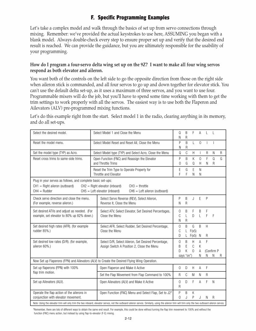
Let’s take a complex model and walk through the basics of set up from servo connections throughmixing. Remember: we’ve provided the actual keystrokes to use here, ASSUMING you began with ablank model. Always double-check every step to ensure proper set up and verify that the desired endresult is reached. We can provide the guidance, but you are ultimately responsible for the usability ofyour programming.
How do I program a four-servo delta wing set up on the 9Z? I want to make all four wing servosrespond as both elevator and aileron.
You want both of the controls on the left side to go the opposite direction from those on the right sidewhen aileron stick is commanded, and all four servos to go up and down together for elevator stick. Youcan't use the default delta set-up, as it uses a maximum of three servos, and you want to use four.Programmable mixers will do the job, but you'll have to spend some time working with them to get thetrim settings to work properly with all the servos. The easiest way is to use both the Flaperon andAilevators (ALV) pre-programmed mixing functions.
Let’s do this example right from the start. Select model 1 in the radio, clearing anything in its memory,and do all set-ups.
Select the desired model. Select Model 1 and Close the Menu Q B F A L LN R
Reset the model menu. Select Model Reset and Reset All, Close the Menu P B L O I IN R
Set the model type (TYP) as Acro. Select Model type (TYP) and Select Acro, Close the Menu Q C H I R N R
Reset cross trims to same-side trims.
Plug in your servos as follows, and complete basic set-ups:
CH1 = Right aileron (outboard) CH2 = Right elevator (inboard) CH3 = throttleCH4 = Rudder CH5 = Left elevator (inboard) CH6 = Left aileron (outboard)
Open Function (FNC) and Reassign the Elevatorand Throttle Trims
P B K O F Q GO G Q H N R
Check servo direction and close the menu.(For example, reverse aileron.)
Select Servo Reverse (REV), Select Aileron,Reverse It, Close the Menu
P B J E PN R
Set desired ATVs and adjust as needed. (Forexample, set elevator to 80% up 82% down.)
Select ATV, Select Elevator, Set Desired Percentages,Close the Menu
O B F B FC L D L F FN R
Set desired high rates (AFR). (for examplerudder 85%.)
Select AFR, Select Rudder, Set Desired Percentage,Close the Menu
O B G B HC L F(x5)D L F(x5) N R
Set desired low rates (D/R). (for example,aileron 60%.)
Now Set up Flaperons (FPN) and Ailevators (ALV) to Create the Desired Flying Wing Operation.
Select D/R, Select Aileron, Set Desired Percentage,Assign Switch A Position 2, Close the Menu
O B H A FB E C KD K O A (Confirm Psays “on”) N N N R
Set up flaperons (FPN) with 100%flap trim motion.
Open Flaperon and Make it Active O D H A F
Set up Ailevators (ALV). Open Ailevators (ALV) and Make it Active O D F A F NR
Operate the flap action of the ailerons inconjunction with elevator movement.
Note: Using the elevator trim will only trim the two inboard, elevator servos, not the outboard aileron servos. Similarly, using the aileron trim will trim only the two outboard aileron servos.
*Remember, there are lots of different ways to obtain the same end result. For example, this could be done without turning the flap trim movement to 100% and without thefunction (FNC) menu action, but instead by using flap-to-elevator (F-E) mixing.
Open Function (FNC) Menu and Select Flap, Set to J2* P B KO J P J N R
Set the Flap Movement from Flap Command to 100% R C M N R
Reset the Trim Type to Operate Properly forThrottle and Elevator
E G E NF F N N
2-12

On my helicopter, I want to set up a “throttle cut” condition which only operates in normal, but notin any of my other conditions. How can I do this? (I am Afraid I'll bump the throttle cut whenreaching for certain other switches--for example, in inverted flight.)
The standard throttle cut (CUT) function is set from the Model Menu, and all the functions listed onthe Model Menu are not "condition" switchable, so it can't do specifically what you're requesting.There are several ways you CAN achieve this, however.
First, you can set the minimum stick position above which the throttle cut (CUT) function will notoperate. For example, you can set it to a point where the throttle cut (CUT) will not operate if the stickis any place above about 1/8 throttle. This way, unless you do a lot of full throttle inverted work, evenif you accidentally bump the switch, you shouldn't have a problem.
Second, you can simply set up a mix in your base condition which offsets throttle to whatever negativepercent will shut off your engine without overcamming your servo (you'll need to experiment to findthis point). Let’s work through this example. (Note: You could create a similar mix also for idle down by simply setting the % for the throttle to decrease and again experimenting until it idles yourengine down to the desired point.)
On my aircraft, I want to set up the left slider as throttle trim.
Note that this can only be done in an aircraft model type. Note that the digital trim also remainsactive unless you deactivate it in the FNC menu.
I am setting up a twin-engined model and want to command the engines separately at certain times.Specifically, I want the engines to respond to the throttle stick (never knobs); the left engine tooperate alone if the C switch is up (the right engine idles); both engines to operate together in the Ccenter position; the right engine to operate alone in the C down position (left engine idles.)
Absolutely! Like most things with the 9Z, there are many ways to tackle this task. We'll give you 3options here. There are many more.
Create a Pmix (PMX) which offsets throttle20% to shut the engine off when at idle. Notethat this switch will idle the engine down butnot necessarily shut it off at higher throttlesettings. (Select the desired percent based onrunning the engine at idle and adjusting thepercent until the engine shuts off.)
Select Pmix (PMX) 1 and Make it Active O B I F A F
Set the Mix Type as Offset D F
Set the Slave as Throttle C G
Set the % as 20% O D I N
Assign the Switch to H and Close the Menu P H P NN N R
Select throttle curve activation, make it active,go to throttle curve and set the volume on theleft slider.
Activate Throttle Curve (TCV) P C L F N R
Select Throttle Curve and Assign Volume to Left Slider O D K O F
Change Direction ONLY IF NEEDED P
Close Volume N
Adjust Curve If Desired (adjust if desired)
Close the Menu N R
2-13

FIRST OPTION: "I have a spare channel on my 8-ch receiver, or am using a 7-ch receiver" (so channel 8 can be used to set up the mixes).
Servo Set-up: channel 3 = left throttle channel 7 = right throttle
Open Function (FNC) Menu, Assign Channels 3 and 7Controls and Trims to Null, Channel 8 Control to ThrottleStick and Trim to Trim 2 for Cross Trims or Trim 3 If YouHave Reversed Cross Trims and Close the Menu
Assuming your spare channel is channel 8,assign channel 8 to throttle stick, and attachthe throttle trim to channel 8. Set channels 3and 7 to null so no knob, slider or switchcontrols those two servos directly – they moveonly by mix commands.
P B KO G P M M EQ EO K P M M EQ EO L P K Q GN R
Open and Activate (ACT) Pmix (PMX) 1Create a pmix (PMX), mixing channel 8 to 3 at100% with trim on, Switch C in up and centerpositions. This will move servo 3 in unisonwith throttle stick movement, including trims,when Switch C is in up and center positions,but not when Switch C is in down position.
O B I F A F
Open Pmix (PMX) 2 and Make it ActiveCreate a pmix (PMX), mixing channel 8 to 7 at100% with trim on, Switch C in center anddown positions. This will move servo 7 inunison with throttle stick movement, includingtrims, when Switch C in center and downpositions, but not when Switch C is in upposition.
O B I G A F
Set Type Linear, Trim Active, Master Mixed, Switch CCtr/dwn
D E R F Q FP C P Q N
Master Aux2 Slave Aux1 B L C K
Set 100% Both Directions and Close the Menu O C M D M NN N R
Set Type Linear, Trim Active, Master Mixed, Switch CUp/Ctr
D E R F Q FP C R Q N
Master Aux2 Slave Throttle B L C G
Set 100% Both Directions and Close the Menu O C M D M NN N R
SECOND OPTION: “I am using an 8-ch receiver and do not have a spare channel.”
Servo Set-up: channel 3 = left throttle channel 7 = right throttle
Open and Activate (ACT) Pmix (PMX) 1Set switch C up position:Pmix (PMX) throttle to 7, 100%, trims follow,with the mix activated by switch C positioncenter and down, then Pmix (PMX) offsetchannel 7 to bring it to idle at the up position.(Note that this set-up mix is offsetting theservo 50%. You may need to adjust thispercent to get a proper idle and notaccidentally shut down the second engine.)
O B I F A F
Select Pmix (PMX) 3 and Make it ActiveSet switch C down position:Pmix (PMX) throttle-to-throttle -100% whichturns off throttle but leaves it at neutral. Again,like we did with mix 2 above, do an offset totake throttle to idle. Set switch C down.
Note: to trim the channel 7 engine by itself,use the right dial. Or turn off the dialassignment in Function (FNC).
Open Function (FNC) Menu and Set Aux1 Assignmentto Null and Close the Function (FNC) Menu.
O B I H A F
Set Type Linear, No Trim, Master Mixed, Switch C down D E R G Q FP C P N
Master Throttle Slave Throttle B G C G
Set Percent -100% Each Way Offset to Idle and Close the Menu
O C M ED M E (Move throttleto idle position) B FN N N R
P B K O KP M M E N R
Type Linear, Trim Active, Master Mixed, Sw C Up/ctr D E R F Q FP C P Q N
Master Throttle Slave Aux1 B G C K
Set 100% Both Directions and Close the Menu O C M D M NN N R
Open and Activate (ACT) Pmix (PMX) 2 O B I G A F
Set Type Offset, Switch C up D F P C R N
Slave Aux 1 C K
Set 50% and Close the Menu O D J F(x10)N N N R
2-14

I want to create a mix which is only active if my throttle is above a certain point. For example, Ionly want my smoke to come on if my throttle is above 1/2 to avoid killing the engine. How can Ido this?
You will use an offset mix with the throttle stick as the on/off trigger rather than a switch. Select ablank pmix (PMX), and mix channel A to channel B. Set up your mix as desired. From the switchscreen, go to stick screen, and select stick J3 – – the throttle stick. Then set the position – – place thethrottle stick in the desired position and press the set key. Now, if you want the mix active ABOVEthis stick position, it’s set; if you want it BELOW this stick position, press +/- to reverse its activedirection.
THIRD OPTION: “Using Conditions. “I want other changes with the engine set-ups.”
Servo Set-up: channel 3 = left throttle channel 7 = right throttle
Turn off ch. 7 assignment so it operatesonly from mixes.
Open Function (FNC), Set Aux1 Null, and Close. P B K O KP M M E N R
Sw. C up position: use offset mix to idle rightengine. Start with 50%, adjust as needed.NO switch assignment, that’s in conditions.
Open and Activate (ACT) Pmix (PMX) 1 O B I F A F
Complete Switch C center position by writingmixes for the second engine’s control. Notethat the pmix (PMX) you created in condition 1is not in this condition.
You can now set up anything else you also want when in this condition...gear position, other mixes, etc. REMEMBER you MUST have the switch in theposition of the condition you desire to adjust.
Set up anything else desired when switch C is down. Need opposite rudder to compensate for yaw? Use an offset mix. Want to drop bombs? Now is the time to set up these additional features and enjoy the 9Z’s power!
W/Sw. C Ctr: Open and Activate (ACT) Pmix (PMX) 1 O B I F A F
Create a pmix (PMX), throttle-to-throttle, witha 100% offset and -100% travel. This willtake the channel 3 throttle to idle.
W/Sw C down: Open PMix 2 (PMX) and Activate (ACT) O B I G A F
Linear, Trim Inhibited, Master Mixed, Switch Null D E R F Q FP I N
Master and Slave Throttle B G B G
Set – 100%, Offset 100% Remember: throttle to idle B F C E M D EM N N N R
Set Type Offset, Switch Null D F P I N
Confirm Linear, Trim Follow D E R F Q F
Master Throttle Slave Aux 1 B G C K
Set 100% Both Directions O C M D M N
Slave Aux 1, Set Rate 50% Close the Menu. C K O D JF(x10) N N N R
Sw. C center position will use a condition.Create it now.
See Instructions for Creating/Copying a Condition. Name it “BOTH” andAssign to Switch C Center Position.
Sw. C down position will use a third condition.create it.
See Instructions for Creating/copying a Condition, Name it “RIGHT,” Switch C Down.
Set up a pmix (PMX) to move smoke servo(channel aux2) – 100% unless throttle isabove a given point. Smoke will not come oneven if the smoke switch is on until throttlepasses the trigger point.
Open Pmix (PMX) 1 and Make it Active O B I F A F
Now assign the function (FNC) of Aux2 toswitch G so that when that switch is off,smoke does not come on, even with throttle.
Go to Function (FNC) Menu P B K
Select Aux 2 Assign to Switch F O L P M J
Close the Menu N R
Select an Offset Mix D F
Select Smoke as Slave C L
Set the Offset to 100% O E M N
Assign to Throttle Stick P O C
Set the Throttle at Desired on Point, Set It, andMake Mix Active below That Point
(move throttle stick to desired position)Q* P N N R
2-15

Operate two aileron servos in unison asailerons and as flaps, including setting up 5%flap trim, which allows adjustment of theflaperon trim position.
Servo Hookup: 1= right aileron 2 = elevator 3 = throttle4 = rudder 5 = BLANK 6 = left ail7 = left flap 8 = right flap
Select Flaperon O D H
Activate (ACT) Flaperon**Note: If Aileron differential (ADF) Is Desired, Set it up Now.
A F
Set Flap Trim at 5% and Close the Menu R C F(x5) N R
Operate the two flap servos from the lefttslider (LS) (remember to adjust your geometryso slider all the way up is 0 flap and slider allthe way down is 100% down flap).
Complete Basic Set-up – Servo reverse (REV), ATV, Dual rate (D/R), Exponential as Desired.
Go to Function (FNC) Menu P B K
Set up Airbrake (ABK) to operate the flaperons(20%) and elevator (-5%) in unison.
Select Airbrake (ABK) O D I
Make Active A G
Select Channel 7 (Au1) and Assign Left Slider (LS) O K P E
Select Channel 8 (Au2) and Assign Left Slider (LS)And Close the Menu
O L P EN R
Set Desired Distances C I D H G(x5)
Confirm Sw C down, Close the Menu P C N N R
Mix each flap servo so it moves 20% inconjunction with the Airbrake (ABK) Functionby doing an offset mix (which just moves theservo a set distance) from the same switchmovement as Airbrake (ABK).
Select Mix 1 (PMX) and Activate (ACT) O B IF A F
Use elevator-to-flap{eron} (E-F) mixing,0% down and 40% up, on switch C inthe up position.
Go to Elevator-to-Flap (E-F) and Make it Active O C K A F
Set Desired Travel C H D J
Confirm Sw. C up and Close the Menu P N N R
Set Offset Type, Aux1 Slave D F C K
Set the Desired Distance O D I N
Assign the Same Switch (C Down) and Close the Mix P C P N N
Repeat for Aux 2 on Mix 2 and Close the Menu G A F D F CL O I N P CP N N N R
How about setting up a complex 7-servo or 8-servo (8th servo being gasoline engine kill switch) onthe 9Z with 2-each flap and aileron servos?
There are many, many different ways to reach the same end result with the 9Z. In this case, let’s take anon-conditions approach. If you want to do the same tasks using conditions, some steps wouldactually be easier in each condition, but there would be more steps overall. If you want to go fartherthan what we’ve set up here, then you may want to play with conditions to complete these tasks.
Before we begin, complete your basic set-up. Choose a model, select the right Pulse Mode (PMD),select an ACRO type model for this approach, etc. Note that the same task could be completed, insome ways faster, using a 4-servo glider set-up.
HINT: If you are not planning on using your inboard flaps in conjunction with your ailerons as fullspan ailerons, then using a y-harness would simplify the programming slightly.
Remember: we’ve provided the actual keystrokes to use here, ASSUMING you began with a blankmodel. Always double-check every step to ensure proper set-up and that the desired end result isreached. We can provide the guidance, but you are ultimately responsible for the usability of yourprogramming.
2-16

That’s one way to set up a complex aerobat. What do we have now?
• Switch C in the up position has flap mixed into elevator for tight loops, sudden dives, etc.
• Switch C in the down position has airbrake which includes both flap servos and the flaperons (FPN).
• Switch C in center and H in up is “normal” flight.
• Switch H in the down position includes rudder-to-aileron (R-A) and rudder-to-elevator mixing forsmooth knife-edge and other rudder applications.
• Left slider movement lowers and raises center flaps without effect on the flaperons.
Want to try some other creative things with this type of an aircraft? Consider twin elevator servos,using the ailevators (ALV) function to have them act in unison with the ailerons for increased rollauthority.
How about a pmix (PMX) from aileron to aux 1 and aux 2, creating full span ailerons? Want to getreally creative? Make this pmix (PMX) with the master mix mode UNMIXED....now the inboardailerons (flaps) will move based upon the full ATV setting of the aileron, regardless of your dual rate(D/R) settings. What does this do? It gives full inboard aileron authority even in situations where youcan’t risk full throw at the tips due to risks of tip stalls, such as harriers, waterfalls, etc.
Want to give it a try? Let’s do it together. Set everything else as described above, but do not set up theoffset pmixes (PMX) for Aux1 and Aux2. The aileron-to-aux pmixes (PMX) here will accomplish aslightly different task this time.
Full Span Aileron Response and Using Master Mode Unmixed.
Use a rudder-to-elevator mix to mixout undesired pitch coupling whenrudder is applied.(You will need to set based upon theperformance of your model. Forexample, +5% each way.)
Go to Pmix (PMX) 3 and Make it Active O B I H A F
Use the rudder-to-aileron (R-A) mix to mix outadverse roll couple when rudder is applied.(This you will need to set based upon theperformance of the model. Ex: -5% each way.)
Select Rudder-to Aileron and Make it Active O C I A F
Set Desired Percent in Each Direction C H G (x5)D H G (x5)
Assign to Switch H and Close the Menu P H P N N R
Set Master to Rudder and Slave to Elevator B H C F
Set the Mix Type to Linear D E
Set the Desired Percent in Each Direction C H F (x5)D H F (x5) N
Assign to Switch H and Close the Menu P H N N N R
Create a pmix (PMX) from aileron to Aux1,100%, always active, trim follow, master modeunmixed, linked into the aileron movement.
(This will move the first flap in conjunction withthe ailerons at all times. This is based upon theaileron stick movement, not the high or low rateaileron setting. Also, it will trim with the ailerontrims, and is active at all times.)
Select Pmix (PMX) 1 and Make it Active O B I FA F
Make it a Linear Mix D E
Make Aileron Master, Linked, and Aux1 Slave B E MC K
Set % to 100% (Adjust to Your Model’s Performance) O C MD M N
Trim Follow Active R F
Master Mix Unmix Q G
No Switch Assignment P I
Close the Menu N N N R
2-17

How can I get my gear doors to open and close delayed to the movement of my gear?
There are a variety of ways to accomplish this challenging set-up. The easiest way to do this is usingtwo additional conditions and a slightly unusual single switch set-up. With this set-up, the gear doorswill open rapidly and the gear will lower slowly when gear is lowered; then when the gear is raised,the gear raises rapidly and the gear doors close slowly behind them.
Get everything else operating exactly as desired in the base condition. {Note, in this example, switch E’s position 1 is the base condition which we will not use in flight (but is required for proper operation of the radio), the 0position is the DOWN condition and the 2 position is the UP condition. Alternatively, the base to gear-down condition could be activated by a switch,slider, or knob positioning after the radio is on, then a 2-position switch could be used to create the up/down scenario.}
Repeat for Aux 2, but follow the channel 6servo not channel 1, and set to -100% tooperate properly as aileron.
Select Pmix (PMX) 2, Make it Active, Linear,Make Master Flap and Linked, Aux 2 Slave,100%, Trim Follow, Master Unmixed, No SwitchAssignment, and Close Menu
O B I GA F D EB E M C LR F Q GP I N OC M E D ME N N N R
Copy the base condition into 2 other conditions,one called “down” and one “up.”
Set up everything as desired in the base condition except the gear-up/down and gear door operation.
See instructions on creating and copying conditions, Section E.
Set the servo slow action in both conditions. With Switch E in 0 Position, Open ATV and Set GearChannel Delay to 100%
O B F R J M
In the gear-up position, offset mix gear 100% With Switch E in 2 Position, Select and Activate (ACT)Pmix (PMX)1
O B I F A F
In the gear-up position, offset mix aux2 100% Select and Activate (ACT) Pmix (PMX) 2Offset, Switch Null, 100%, Close the Menu
G A F D F PI N C L O MN N N R
Offset, Switch Null, 100%, Gear D F P I NC I O M N N
Move Switch E to 2 Position, Set Door Delay to 100% O M M N R
2-18

CHAPTER III. GLOSSARY OF TERMS, KEYSTROKE COMMANDS, ANDPRIMARY MANUAL PAGE REFERENCES
All terms and abbreviations are in alphabetical order, with abbreviations listed with manual pagereferences then keystroke comands to activiate. For Example, P. 1.4. Q A I indicates chapter 1 page 4 ofthis guide, and access by pressing key Q then A then I. Note: If a feature is used in more than onemodel type, such as ADF in acro and glider, the keypad strokes to open the feature are identical.
Abbrev.Page #Keys
Feature Description and Page References for Futaba Instruction-and-Operation Manual and World Championand World Champion II Addendums
A➝RO C G
Aileron-to-Rudder Mixing. Air and all gliders only. Mix from aileron to rudder which automatically creates a“coordinated turn” and keeps model from sliding in turns. Manual P. 81.
ABEO C J
Airbrake (or gear)-to-elevator mix. For trim compensation: all gliders only. This pre-programmed mix applies up ordown elevator when airbrake or gear are deployed, correcting for any pitch change from the added drag. Manual P. 129.
ABKP. 2-15O D I
Airbrake. Air only. Combines elevator, flap, and optionally spoilers to suddenly slow the model for spot landings.May be triggered by throttle position. Manual P. 91.
ABT Abort. Used to terminate certain accidental settings such as selecting the wrong channel while in the FRQ option.
ACCO D J
Acceleration. Heli only. This is a unique delay mix. When throttle is applied, opposite rudder is automatically appliedto counter torque, then gradually decreased to 0. Set up is complex, setting the desired amount of rudder at immediateresponse and the delay time to compensate. Heading-hold gyros provide this automatically. Manual P. 116.
Acro Powered aircraft model type. See TYP.
ACT
Adjustable Function Rate: see AFR.
Adjustable Servo Travel: see AST.
Activate. Make a feature able to be utilized. While inhibited, a function can not be used even if the assigned switch is on.Setting a feature from ACT to INH turns off its functionality without losing any settings. Only in specific features.
ADFP. 2-4O C F
Aileron Differential. Decreased down aileron travel when compared to up aileron travel. Minimizes “dragging”the low wing and creates more axial rolls. Manual P. 80.
AFRP. 2-2O B G
Adjustable function rate, high rate. Adjusts the travel in each direction of a function. For example, used to adjusttotal aileron travel whether ailerons are a single servo in channel 1, or two servos set up as flaperons, elevons, oraileron differential. Manual P. 62.
ALTP C K
Alternate switch. Sets the action of the spring-loaded switch. Normal is “on” only when switch is heldon. Alt is one pull to turn on, a second pull to turn off. Manual P. 52.
ALVP. 2-4O D G
Ailevators. Air only. Twin elevator servos plugged into separate channels used to control elevator with the option to alsohave the 2 elevator servos act as ailerons in conjunction with the primary ailerons. Manual P. 88.
ASFO C H
Aileron-to-speed flap mix. 4- and 5-servo gliders only. This is a pre-programmed mix which commands the speed flaps(main flaps on a 5-servo glider) to operate in unison with the ailerons. Manual P. 127.
Aileron Differential: See ADF; also a sub-feature of Flaperon, FPN.
Aileron to Speed Flap mixing: see ASF.
Ailevators: see ALV.
Air: Aircraft model type. See Acro and TYP.
Airbrake function. See ABK.
Airbrake trim mix. See ABE
Alternate switch set up: see ALT.
AST: Adjustable servo travel. End point adjustment which has only a single adjustment for both ends of the servo travel.Not used on 9Z. See ATV.
ATVP. 2-2O B F
Older, less clear terminology for end point adjustment. See EPA.Manual P. 60.
3-1

AUT Auto, automatic. Allow a specific feature to be triggered automatically based on pre-programmed inputs ratherthan user input during flight. For example, see Airbrake.
Auto-Shut OffP. 1-10Q C G A
Backup battery: lithium battery in the 9Z which maintains memory when the transmitter battery is removed. See P. 1-9.
Safety feature which shuts off the 9Z after a set period of time of inactivity to avoid draining the transmitter battery.Manual P. 33.
BFSP. 1-6P B H R
Battery FailSafe function. Determines how to regain throttle control after a Receiver low battery warning. Defaults:56% throttle and requires throttle to idle before allowing throttle again. To adjust the warning point, set a throttleposition in F/S. To adjust the “reset command” to regain throttle control, seelct the desired switch/stick/etc in BFS.
BFYO D G
Butterfly, Crow. 4- and 5-servo gliders only. A preprogrammed mix which activates up flaperons and down flaps forgliding speed control without spoilers or airbrakes. Volume of butterfly is adjustable in flight. Manual P. 140.Note: Similar programming is available in acro mode with airbrake (ABK) function.
BKFO C L
Brake Flap Mixing: See BKF.
Butterfly: see BFY.
Butterfly-to-elevator mixing: See BYE.
Brake flap mixing. Three mixes: brake flap- to-elevator, to-aileron and to-speed flaps. (Each adjustable)1) compensate for unwanted reaction to lowering the brake flap, 2) increase brake flap area by including the flaperons,and 3) add lift to increase manueverability. The neutral point of these mixes can be moved from the brake flap’sneutral. 5-servo gliders only. Manual P. 132.
BYEO D H
Butterfly-to-elevator mixing. 4- and 5-servo gliders only. A preprogrammed mix to deploy elevator to compensate forballooning caused by butterfly. Adjusted proportionally with the in-flight adjustment of butterfly. Manual P. 142.
CHDP. 2-10G or O M
Condition hold. Holds the actual output to the model in the last condition, allowing the user to make adjustments toother conditions safely without having the model receive the commands for that condition. Used to keep the modelidling safely on the ground while adjustments are made to throttle hold, idle up, gear up, smoke on, full throttle, orother equipment combinations which can not be active on the ground. Manual P. 40.
CH9 Channel 9 switch selection. Manual P. 50. P C I.
Band: See Frequency Band.
Battery FailSafe: see BFS.
Butterfly pitch correction: See BYE.
Campac: Optional extended data storage module for the 9Z. Manual P. 12. See P. 1-3, 1-4
CCPM: Cyclic-Collective-Pitch-Mixing. Type of swashplate mixing which requires a radio with CCPM mixing functions. This uses threeservos to control the cyclic, while all three work together to raise and lower the swashplate for collective control. See SWH.
Channel delay: A feature within ATV which slows servo operation. See P. 2-3 and 2-17.
Channel Select: See FRQ.
Choke: see P. 1-5.
CMB: Combine feature within trim menu. See TRM. See P . 2-11.
CND: Condition menu. Returns to Conditions menu. Usually key O in menu screens.
Collective Pitch: See CPT.
Condition: Separate flight model which has nearly 100% adjustability separate from the basic model set-up. (Can not adjust items in themodel menu.) See Chapter 2 Section E.
Condition Hold: See CHD.
Condition Menu. See CND.
Condition Name. See CNA.
Condition Select: See CSL.
Copy condition. See CPC.
Copy model. See CPM.
CNAP. 2-10O B L
Condition Name. Used to name each flight condition to minimize confusion during set up and use. Hint: werecommend naming your base condition the frequency used with your FSS module for easy channel recognitionduring model select (MSL). Manual P. 70.
3-2

CPMP. 1-3Q B L
Copy model. Used to duplicate the settings of one model already in memory into a second model memory. Often usedto set up 2 similar models, or make a copy of a working model to experiment with new set-ups. Also used to copymodels to/from the Campac data storage unit. Manual P. 31.
CPTO D F
Collective pitch. Air only. Used to regulate variable pitch props to slow model and keep engine running in vertical divesand provide maximum torque in model’s vertical climbs. Idle trim is used for how high the idle is when in reverse pitch(diving) and the pitch trim finely adjusts the amount of pitch at full throttle to avoid over-propping the engine. Manual P. 87.
CSLP. 2-10P B F
Condition Select. Used to select and assign a flight condition to the model currently in use. Manual P. 40.
CUTP. 2-12P C F
Engine cut, also known as throttle kill. Used to safely shut engine off. Manual P. 47.
Cross-trim: Trimmer next to throttle adjusts elevator and the trimmer next to elevator adjusts throttle. To revert to normal trim, see P. 2-3.
Crow: see BFY (glider types) and ABK (acro type).
Data Transfer: DTN.
CX: see Crystal.
Delay Mix: Mix which responds, instantaneously, then decreases response over a delay. See ACC.
DTNQ B K
Data Transfer. Copies data between 9Zs through the trainer cord. Manual P. 30.
D/RP. 2-2O B H
Dual rate, or low rate. Used to decrease control throw in certain circumstances. Manual P. 64.
ESFO C K
P. 2-2O B F
Elevator to speed flap mix: 4-servo gliders only. This is a pre-programmed mix from elevator to the speed flaps(primary flaps) to increase lift for tighter turns, etc. Manual P. 131.
E➝FP. 2-15O C K
Elevator-to-flap mixing. Air and 2-servo gliders only. Used to apply flaps along with elevators to increase lift,allowing modeler to fly at slower speeds, make tighter loops or turns, etc. Manual P. 85.
EBFO C K
Elevator-to- brake flap mix. 5-servo gliders only. This is a pre-programmed mix from elevator to the brake flaps (smallcentermost flaps) to increase lift for tighter turns, etc. Manual P. 130.
Differential: uneven movement in each direction of a control surface. Usually used when discussing ailerons or when describing anundesired unevenness in movement of other controls. See ADF.
Diode: An electronic component which only allows current to flow one direction. See P. 1-9.
Dual Aileron Servos: See ADF and FPN.
Dual Elevator Servos: See ALV.
Dual rate: see D/R for low rate and AFR for high rate.
Elapsed Time Counter reset: See T/R.
Elevator-to-brake flap mixing: See EBF.
Elevator-to-flap mixing: See E*F.
Elevator-to-speed flap mixing: See ESF.
Elevator trims, glider programming. See ETM.
Elevon: See EVN.
END: Returns to previous menu.
Engine cut: See CUT.
EPA End point adjustment. (Called ATV in 9Z) Adjusts the total travel in each direction of servos regardless of their controlassignment. For example, adjustment to AIL channel will adjust only the servo plugged into channel 1 regardless offlaperon, elevon. Manual P. 60.
CPCP. 2-10Q C F
Copy condition. Used to copy one condition into another. Often used to duplicate a working base condition intoadditional conditions to minimize repeating set up steps. Manual P. 32.
3-3

EVNP. 2-4O C J
Elevon. Air only. Used for delta wing and tailless aircraft which have 2 servos operating 2 aileron-like controlsurfaces as both elevator and aileron. Manual P. 84.
F➝EO C L
Flap-to-elevator mixing. Air and 2-servo gliders only. Used to counteract unwanted changes in pitch whenflaps are deployed. Manual P. 86.
FMCP D FO F L
Fuel mixture control. Air and Heli only. Used to command a second servo which adjusts the fuel mixture at thecarburetor for different throttle position settings. Addendum P. 9. (P D F to make active, then O F L to adjust.)
FNCP. 2-5P B J
Function menu. Used to assign specific features to specific stick/switch/slider/knobs. For example, flap control canbe moved to a switch by simply changing function assignments. Also, the trims can be assigned to any of channels 1-8and set to normal or to throttle-style (alt) where trim control affects only below center. Manual P. 45.
FPNP. 2-5O D H
Frequency: Channel on which radio transmits. See FRQ. For chart see P. 1-2.
Fuel Mixture Control: See FMC.
Frequency band: In the entire frequency spectrum, transmissions are designated in terms of "frequency bands" which exhibit similarproperties and in the lower region the bands are useful in radio communication. In the US, specific frequencies within the72MHz band are regulated by the FCC to be used solely for remote control aircraft (including helicopters, blimps, etc.)50MHz band is available for model use (for air or ground) only by those holding a HAM Amateur radio license. 75MHz issolely for remote control ground models (boats, cars, robots, etc). 27MHz is legal for air or ground use.
Flaperons. Air and 2-servo gliders only. Twin aileron servos plugged into separate channels used to control aileron,with the option to also have the 2 aileron servos act as flaps. Includes aileron differential capability. Manual P. 89.
FailSafe: See F/S.
Flap-to-elevator mixing: See F@E.
Flaperon: See FPN.
FRQP. 1-1Q C I
Frequency. Used to select 72mHz frequency to use when utilizing the FSS synth module. This option displays only ifFSS was installed prior to 9Z being turned on. (All 9Z models support the FSS module.) Manual P. 35.
F/SP. 1-6P B H
FailSafe menu. Sets servo positions when interference is encountered or signal is lost. Available only in PCMtransmission mode. Also includes Battery FailSafe (BFS) settings. Manual P. 42.
GYRO D I
Gyro sensitivity. Heli only. Create stick priority or activate dual rates by stick position. Decreases the gaindirectly proportional rudder input (or steps from high to low rate on dual rate gyros.) Manual P. 114.
EXPN: Exponential. See P. 2-2.
Exponential. See P. 2-2.
Function menu: See FNC.
Gear trim mix: See ABE.
GL2: Model type, glider with 2 wing servos. See TYP, and P. 2-1.
GL4: Model type, glider with 4 wing servos. See TYP, and P. 2-1.
GL5: Model type, glider with 5 wing servos. See TYP, and P. 2-1.
Gyro sensitivity: See GYR.
Hel: Model type, rotary wing. See TYP.
Helicopter: Rotary wing model type. See TYP.
High Rate: See AFR.
HOM: Home menu. Returns to home screen. Usually key R in menu screens.
Home: See HOM.
FSS: see TK-FSS.
HLDO C L
Throttle hold. Heli only. This is a linear mix with an offset. This mix makes the throttle servo non-responsive to stickposition, and moves the throttle to idle. To practice autorotations. NOTE: a helicopter model type pre-assigns acondition specifically for throttle hold; however, it does not assign anything to this condition. Besides activating throttlehold, you will need to create pitch curves for blade inertia to increase during the drop, and sufficient pitch to bring thehelicopter to a hover and land. Manual P. 110.
ETMO D I
Elevator trim. 2- and 5-servo gliders only. Two separate offset mixes for the elevator to allow pre-programmedelevator settings, for example, for thermal hunting, penetrating, gliding, etc. Manual P. 143.
3-4

HOFO C K
Hovering offset. Heli only. Adjusts the center point of the pitch curves, including the hovering pitch curve, to fine-tune thehovering point when it is not exactly center throttle stick position. Manual P.109.
INVP D HO D K
Inverted flight control. Heli only. Activates inverted flight programming, which reverses the rudder, pitch and elevatorservos, and sets up inverted flight pitch high-side and low-side. Allows the radio inputs to be identical to upright flightwhile the model is inverted. Manual P. 57 and P. 117.Note: this approach to hovering is seldom used. Instead, idle-ups are used and the modeler learns to respond to thecontrols’ reversal in inverted flight.
MNAP C J
Q C G
Model name, up to 8 characters long. Used to identify different model memories.
LST List, to open a listing of available models, conditions, etc.
MAN Manual, not automatic. For example, see airbrake.
INH Inhibit. Makes a feature inactive/unable to be used. When a function is inhibited, it can not be used even if the assignedswitch is moved to the on position. Setting a feature to INH turns off its functionality without losing any settings.Only visible in specific features.
Hover: To maintain a stationary position in which the model is not climbing, diving, rolling or yawing.
Hovering offset: See HOF.
Hovering pitch: See PHV.
Hovering throttle: See THV.
Idle-up: Separate condition created to allow inverted and other types of flight with a helicopter not easily achieved in the normal condition.Note: the 9Z is fully programmable and nothing is pre-assigned into the idle-up conditions. Manual P. 101.
In-flight needle control. See FMC.
Inhibit: see INH.
Inverted: To fly a model upside-down.
Inverted flight control programming: See INV.
Limit Mode: ATV mode setting which limits the maximum servo travel in WC and WC2. See ATV. See P. 2-2.
LIN: Linear, directly proportional.
LINK: Mixing function which allows multiple mixes to work in conjunction. See PMX. See P. 2-9.
Lithium battery: See backup battery.
Master Mix Mode: Mix option which causes slave channel to operate based on master channel’s ATV, not AFR or D/R settings. See PMX.See P. 2-8, and 2-16.
Mix: See Pmix.
Model name: See MNA.
Mixer: Trainer function that allows instructor to make corrections without taking back control. See TRN. P. 1-10.
Model selection: See MSL.
Model type: See TYP.
Modulation: Means of transmitting data. See PMD, also PPM, PCM.
MSL: Model selection. Used to choose the model you desire to use. Q B F.
Name: See MNA for model name, CNA for condition name, UNA for user name.
Noise trap: see P. 1-5.
NUL: Null. Not assigned or never changed. For example, a mix which has a null switch assignment is always active no matterwhat switch is moved.
NXT: Next. Continue to next screen within a feature.
PAR Parameter submenu. Sets auto-off timer and screen contrast. Manual P. 33.
Module: Electronic device which can easily be removed/replaced into the transmitter, which houses all transmission components.Transmission frequency can be safely, legally and easily changed (including from band to band) by changing the module. TK-FSS isthe synthesized module which transmits on any 72 MHz frequency. TK-FM is the standard module, available on any 50MHz or 72MHzfrequency. Can be converted to 75MHz frequency for ground use. See Chapter 1.
P➝RO D G
Pitch to rudder. Heli only. This mix, also known as revolution or tail rotor mix, counters torque (caused by addingpitch) with opposite direction rudder, keeping the helicopter from rotating as a result of the increased torque. Notrequired with the use of a heading-hold gyro, which self-counters the torque-caused movement. Manual P.112.
Low rate: See D/R.
3-5

PCVO C F
Pitch curve. Heli only. Curve mix which gives 13 points along the throttle stick (or other control – – see PIT)movement to fine-tune the pitch response. Manual P. 104. NOTE: PHV, PTM, and HOF fine tune this curve.
PHVO C G
Hovering pitch. Heli only. Hovering-type mix which gives an in-flight adjustment to the pitch curve at and aroundcenter stick (the center-point of this feature can be adjusted with the hovering offset command) to give very fine-tuningfor easiest hovering. Manual P. 105.
PITP D I
Pitch curve activation. Heli only. Used to attach the pitch channel to the throttle stick. Pitch curve may be disabled oroperated by a control other than the throttle stick, for example, in fixed pitch and dual rotor helicopters (which usedifferential throttle to adjust pitch, not a pitch command.) Manual P. 58.NOTE: Manual says this turns pitch curve function on/off; however, PCV, pitch curve, actually remains functional if you
reassign pitch to a different control such as a slider.
PMDCh. 1 Sec. EP B I
Pulse Modulation. Used to select FM (PPM) or PCM to match the particular receiver being used. Transmitter must beturned off and back on to activate new modulation. Manual P. 43.
PMXCh. 2 Sec. DO B I
PPM: Pulse Position Modulation: an analog method for encoding data as a time position of a narrow signal pulse, where amplitude isconstant, but pulse width and pulse position are changed. Saying it is the same as FM isn't accurate, but a misnomer used bymodelers for years. See PPD.
Programmable mix. Used to cause specific servo responses to specific inputs separate from the basic control set-ups.Manual P. 65.
PTMO C H
Pitch Trim. Heli only. Offsets the entire pitch curve, increasing or decreasing responsiveness proportionally at all points.Adjustable in flight.
R➝AP. 2-16O C I
Rudder-to-Aileron Mixing. Air only. Used to counteract undesirable roll (roll coupling) which often happens withrudder input, especially in knife edge. Gives proper aileron input to counteract roll coupling when rudder isapplied. Manual P. 83.
R➝TO D H
Rudder-to-throttle. Heli only. Adds throttle to counter the added load from increasing pitch of tail blades, maintaininga constant head-speed with rudder. (This is a minor effect and is not critical for most helicopters.) Manual P.113.
RDR P D G
Rotor direction. Heli only. Sets rotor’s rotational direction for proper mixing. Manual P. 56.
REVP B J
Servo reversing. Used to reverse the direction of a servo to ease installation and set up. Manual P. 44.
PA2: Pilot Assist. Optional onboard device which uses optical sensors to correct model’s orientation to upright. See P. 1-7
Pitch Curve: See PCV for pitch curve adjustment; PIT for pitch curve attachment to throttle.
Pitch for Hover: See PHV.
Pitch-to-rudder: See P*R.
Pitch Trim: See PTM.
PCM: Pulse Code Modulation. Analog signals are encoded into a stream of digits, coded as a series of pulses for transmission to thereceiver. The greater number of samples in the digital signal (i.e. 1024 vs. 512), the greater the resolution and control precision.An increased signal-to-noise ratio allows PCM systems to exibit minimal effects from interference. PCM actually refers to the wayin which data can be ARRANGED, not the method in which it is transmitted. See PMD.
PRE: Previous. Return to previous screen within a feature.
PT➝: Next point to the right in the curve. Used in curve mix programming.
PT : Next point to the left in the curve.
:Rapid acceleration correction mix: See ACC.
Reset: See RST.
RSTP B L
Reset, return to defaults. Used to reset the timers at Home B or C. Also a model submenu used to reset part or all of aspecific model’s settings. Manual P. 46.
Rotor direction: See RDR.
Rudder-to-aileron mixing: See R➝A.
3-6
➝

SFTO D F
Speed flap trim: 4- and 5-servo gliders only. Trim adjustment for speed flaps (an offset mix) which can beadjusted in flight. Manual P. 139.
SNPO D J
Snap roll. Combines rudder, elevator and aileron movement to cause the aircraft to snap or spin on the flip of a switch.Air only. Manual P. 93.
SPFO C L
Speed flap mixing: 4-servo gliders only. See brake flap mixing, but for 4-servo gliders (no brake flap to speed flap option).Manual P. 135.
STMO B J
Sub trim. Used to fine tune the center or neutral point of each servo. Allows full trim function from the trim slidersfor flight trimming. Manual P. 68.
SWHP D F
Swashplate type. Heli only. Selects specific heli swash geometry, such as “CCPM”. Swash plate rotation can beadjusted in SWP in the condition menu if heli’s specific geometry does not match the positioning of the stock swashtypes. Manual P. 54.
SWPO D F
Swash plate adjustment. Heli only. This feature includes swash-to-throttle mixing, used to add throttle during cycliccommands for constant engine RPM. It also includes swash rotation, used to correct for a model whose set-up has theswash plate shifted a certain angle from the pre-defined swash plate types in the model menu (SWH) or to fine-tune rollor looping maneuvers due to rotor blade phasing differences. Manual P. 111.
TACQ B H
Tachometer, Reads RPM of propeller or rotor head. Manual P. 27. (Can also be activated from Home G.)
Rudder-to-throttle mixing: See R*T.
RX: See Receiver.
Sailplane: Glider, non-powered model aircraft type. See TYP.
SEL: Select, choose control to be edited.
Select or set a condition, assign a condition to a model: See CSL.
Select a model: See MSL
SEP: Separate trims, option of trim menu. See TRM.
Servo testing, servo display: See SRV.
Servo reversing: RVS.
Servo slow: see Channel Delay.
SET: Accept.
Snap roll: See SNP.
Speed flap: the middle control surface on a 6-trailing-edge-surface glider or the inboard control surface on a 4-surface glider.
Speed flap mixing: See SPF.
Speed flap trim or speed flap offset mixing: See SFT.
S/S: Start/stop, used to activate/deactivate the timers. Home A or D.
SRVQ B I
Servo Test/Display. Test feature checks proper servo operation/speed/travel by cycling each servo very slowly. Displayfeature shows a bar graph indicating movement of each servo. Example: use servo display to plan and test complexradio programming prior to installation into a model to experiment with how best to accomplish a certain goal.
Start/stop: See S/S.
Subtrim: See STM.
STK Stick setting. Used to assign the specific feature(s) to a particular gimbal’s movement. Often attached to SWTand VOL screens. Manual P. 37. Available only from within a feature which has switch assignment.
Swashplate: See SWH.
Switch programmability: See SWT.
SWT Switch setting. Used to assign the specific feature(s) to a switch. Often attached to STK and VOLscreens. Manual P. 37. Available only from within a feature which has switch assignment.
SYS: System menu. Returns to System menu. Usually key Q in menu screens.
Synthesized module/receiver: TK-FSS and R309DPS. Allow modeler selection of any US aircraft-legal 72MHz frequency. See Module. SeeChapter 1 Section A and Manual P. 35 & 36.
Synthesized channel selection: See FRQ.
SX: see Servo.
3-7

TCVP. 2-12O C I
Throttle curve. Air and Heli only. Adjusts how the throttle servo responds to the throttle stick position along a 13 pointcurve. Low point can be adjusted in flight with volume control. Often used to make actual engine response more linearto throttle stick position. Manual P. 94. O D K. Heli note: Hovering throttle allows even finer tuning adjustment to thiscurve around center stick. Manual P. 106.
THRP C L
Throttle curve activation. Air and Heli only. Activates the throttle curve feature (See TCV) Manual P. 53.
THVO C J
Hovering throttle. Heli only. This is a pre-programmed hovering-type mix which gives an in-flight adjustment to thethrottle curve at and around center stick (the desired hovering point) to give very fine tuning for easiest hovering.Manual P. 107.
TM1 and TM2O D I
L and Msimultaneously.
Trim mix 1 & 2. 4-servo gliders only. Trim presets available for 4-servo glider which includes ETMfunction but also similar trim functions for aileron and speed flaps as well. Manual P. 145.
Tachometer: See TAC.
Thermal hunting: Using specific programming set-ups to have the model respond noticeably to the lift of a thermal. See ETM and TM1.
Throttle curve activation: See THR.
Throttle curve adjustment: See TCV.
Throttle cut or throttle kill: See CUT.
Timer: See TIM.
Timer Start/Stop: See S/S.
Timer Reset for master timer: See T/S.
TK-FM: single-frequency module for 9Z. See Module. See Chapter 1 Section A.
TMR: Timer. Abbreviation for timer used on timer displays.
TP-FM: Module not designed for 9Z. See P. 1-3.
Trainer: See TRN.
Trim menu: See TRM.
Trim mix (for thermal hunting): See TM1.
Trim offset: See TOF.
Trim option in mixes: See PMX. See P. 2-8.
Triple rate: 3rd control travel setting available in flight. See D/R and P. 2-6.
T/R Elapsed timer reset. Press the two T/R keys together to reset the radio’s master “time on” elapsed time display in theupper right corner. Often used to track time between charges, and radio use hours between routine service.
TRM Trim menu. Used to memorize current digital trim positions, set trim type, % of trim delay when switching fromcondition to condition, sound on or off when trimmers used, rate of trim response at 2 different lengths of time held,and having trims affect all conditions or only the current condition. For example, store trim positions to memory oncemodel is perfectly trimmed. Adjust CG and re-fly, re-trim. Amount of trim change caused by adjustment to aircraft isnow easily measured. To activate additional features of trim menu, select the specific trimmer, T1-T4, and adjust asdesired. Manual P. 71.
Trim follow: Trim combine/separate feature of trim menu. Allows trim adjustments in one condition to affect or not affect other conditions.Trim option in mixes: See PMX.
TK-FSS: synthesized frequency module for 9Z. See Module, Synthesized Module. See Chapter 1 Section A.
Throttle hold: See HLD.
TIMP B G
Timer. Adjusts the 2 timer functions. For timer which shuts radio off when not in use, See PAR sub menu.For elapsed timer, See T/R. P41. Can also be reached from Home H.
3-8
P. 2-11E
TOFO B K
Trim offset. Sets an offset or adjustment of trim when switching between conditions. For example, applying upelevator trim when switching from an upright to an inverted flight condition to keep the aircraft flying straight and level.Manual P. 69.

TYPP. 2-1P C H
P. 1-10Q B H
Model type. Select basic programming for the selected model: airplane, glider (2, 4 or 5 servos), or helicopter.All model settings are lost if the model type is changed. Manual P. 49.
UNAQ C H
User Name. Enter user’s name and security code. Manual P. 34.
VLTQ B G
Voltmeter. Voltage reading. Displays transmitter and receiver voltage (through the DSC cord) including adjustable load.Visible on home screen if Timer 2 display is turned off (TIM). Manual P.41. Can also be accessed from Home I.
VTLP. 2-4O C H
V-tail model Mixing. Air and all gliders only. Used on a v-tail model to have 2 servos operate 2 control surfacesas both rudder and elevator. Manual P. 82.
TRN Trainer system. Controls channels and features provided to student. Manual P.29.
Twin elevator servos: See ALV.
Twin aileron servos: See FPN and ADF.
TX: see Transmitter.
User name: See UNA.
Variable Pitch Prop Control: See CPT.
VOL: Volume setting. Used to assign the control which adjusts the volume, or amount, of response in specific features. For example,pitch curve volume can be assigned to a dial or slider to be adjusted. Often attached to STK and SWT screens. Manual P. 37.Available only within features with volume assign ability.
Voltage reading: See VLT.
Voltmeter: See VLT.
Volume: See VOL.
V-tail: See VTL.
XTAL: see Crystal.
3-9© Copyright 2001 — 3005225 FUTZ8952