Embed Size (px)
Citation preview

Airplane Section
SAMPLE AIRPLANE SETUP INSTRUCTIONS
The following example shows how the PCM1024Z may be programmed for a pattern airplane.The settings presented here are for a typicalmodel. Your model's settings are likely to varyfrom these, but the procedures given will still beapplicable.
1. Model SelectionUse the Model Select function MSL to select a
vacant model memory (or one you don't mind erasing)and choose the AIRPLANE Setup using the TypeTYP function from Model menu.
2. Name The New ModelRename the model using the Model Name MNA
function in the model menu. Switch to the Conditionmenu CND and name the default flight condition(we recommend NORM L). Later you may add otherflight conditions, which may also be named to makethem easier to identify.
3. Activate Special MixingActivate Flaperon FPN or Aileron Diferential
ADF if you desire these functions (you may onlychoose one; both require two aileron servos). FPN issuggested since it can accommodate differentialthrough end point adjustments, and has Flap mixing.The Flap mixing is used to have the ailerons behave asflaps as well, which can be used to make tighter loopsand squarer corners in maneuvers. Use ALV to getelevators that act as ailerons (two servos are requiredfor ALV function). You need not adjust the throwsand mixing ratios at this time.
4. Reset Control OrderIf necessary, reset the Control Order using the
Function Control FNC in the model menu. Here youmay choose what sticks and sliders control the dif-ferent functions. If you use the ALV function, movethe retract operation to another switch, perhaps CH7orCH8.
5. Connect ServosPlug Servos into Correct Channel Numbers
1. AIL Aileron (Ail 1 if FPN or ADF on)2. ELE Elevator3. THR Throttle4. RUD Rudder5. GEA Landing Gear (Elev 2 if ALV on)6. FLP Flap (Ail 2 if FPN activated)7. AU1 Spoiler (Ail 2 if ADF is used)8. AU2 Collective Pitch9. CH9 Channel 9
6. Set Neutral PointsUse the Subtrim function STM to move each
servo to its neutral position. If the amount of subtrimis large, you should reset the subtrim to zero and movethe splined servo arm to a position that is as close tothe desired neutral as possible. Then use the subtrimto get the neutral position "right on." Repeat with theremaining channels.
7. Adjust Servo ThrowsCheck the proper direction of throw for each
servo. Use Reversing Function REV in the Modelmenu to set proper throw directions for each servo.Double check that each servo moves the proper direc-tion.
8. Limit Servo ThrowsNow use the ATV function to limit servo throws.
The travel of the ailerons should be limited to roughly10—12° maximum in both directions with the ATVfunction. Repeat for elevator. Adjust rudder lateralmotion to about ±45°. Be sure that no servo "bottomsout" at maximum control throw. After setting maxi-mum throws, ATV is rarely used. Instead use AFR inthe different flight modes.
9. Changing The Control FeelIf you would like to soften the control feel for
ailerons, use the AFR menu. Press the NXT key,then the EX1 key to get exponential curve. Set arate of -15% to -25%. EX2 is used for throttle only.
Change to Elevator using the Channel key. Use theAFR to get slightly more up than down travel, and useEX1 with a -10% setting.
Change to Rudder with the Channel key, and setEX1 for-10%.
Airplane Section, Page 77

Airplane Section
10. Set Flaperon ThrowsNow go back to the FPN (Flaperon) menu. Set
differential by limiting the down aileron throws onboth sides. The down throw should be set between70% and 95% of the up throw. This setting depends onthe individual model and its particular flight character-istics, so make changes after flight testing. Be surethat the flap mixing settings are the same (default is±100%).
Move to the E->F menu to set up how much theailerons move due to elevator. Approximately 10-30% up and down mixing should be used (be sure thatup elevator causes the ailerons to drop, and downelevator raises the ailerons up). The amount of ailerondroop at neutral elevator may be set with the A knob.You may adjust this travel by adjusting the trim rate —it can be set to zero to prevent accidental changes (besure this knob is zeroed before resetting subtrims).Using the SWT button, you can also define a switchto turn the elevator-flaperon mixing on and off.
11. Setting Up AirbrakesTo make landings easier, you may set a switch to
move both the elevators and flaps to a preset positionfor an airbrake effect. Normally, the ailerons are raised5—10° and the elevator is offset to cancel any trimchange.
Call the Airbrake ABK function from the con-dition menu. Select the Manual mode by pressing theMAN key. Auto is available.
This system should normally be used in manualmode. To select the operating switch, press the SWTkey. The display shows that the default airbrake con-trol switch is the C switch, ON in the lower position.You may choose another switch or direction at thistime. Verify proper operation of the switch by activat-ing it and watching the servos move.
Press the PRE key to get back to the precedingkey. If you have spoilers, they may be actuated also.Read the section on ABK for more details.
12. Snap Roll SetupYou may have any switch activate the Snap Roll
function (the spring-loaded switch is strongly recom-mended!). Call the Snap Roll function SNP formthe Condition menu. Activate it with the ACT key.
Set the deflection for each switch position: ailerons±100-110%, elevator ±80-100%, rudder ±70-80%.Be sure to choose the correct directions with the
For safety, you may also turn on the safety switchusing the O button. This safety inhibits the activationof snap roll if the landing gear are down. Check tomake sure the switch is set for the correct direction.
13. Setting Up Differential ElevatorYour PCM 1024Z system has a unique function
called ALV for "Ailevators," or differential elevators.This function provides roll control whenever thepropeller slipstream is acting on the tail, and is effec-tive at low airspeeds.
Press the ALV key to enter the menu. Activatewith the ACT key, then adjust the rates given by theA-3 and A-4 settings. We recommend starting out withsmall deflections at first. Be sure that the settings forELE are 100% to get full elevator authority.
Airplane Section, Page 78

Airplane Section
14. Flight Conditions SwitchingIf you like, you may set up the system to call up
more than one function or switch to a new set of trimsor control settings simultaneously by moving a singleswitch. You can have different subtrims, coupling,differential, exponentials, and throw volumes. In factyou may change EVERY parameter between flightmodes.
We recommend that you fly the model and adjusttrims and control responses to your liking beforedefining another flight condition. Any bad tendenciesmay be corrected with custom programmable mixsettings PMX . Then, copy the set of adjustments toa new flight condition, where they may be modifiedfor the new desired conditions. After copying youmay add new functions as necessary.
Use the Condition Select CSL button in theModel Menu. This function allocates the necessarynumber of flight conditions to the model memory.Note the condition number next to the D (default) inthe display. This is the set of conditions that will becopied into a new condition and modified. Also notethe number after the next display. You will copy tothis condition.
Use the Copy Condition CPC from the Systemmenu. This function copies the contents of one condi-tion into another. Choose the default flight conditionnumber, press the SET button, then choose the secondcondition number in the lower box "TO CONDI-TION." Give the command to copy.
15. Volume SettingSome functions can have their mixing ratio vary
with the motion of another slider or knob: use theVOL key O to get to this choice (for example, seeADF). Move the selected control to determine how itaffects the mix. You can also add a time delay onmany of the menus: look for a DELAY setting.
16. Programmable MixersUp to five mixers are available in all flight condi-
tions. These may be used to enhance flight capabilitiesor to correct bad tendencies by adjusting mixing fromone control to another. For example, you may useElevator->Flap coupling to tighten up the corners onsquare loops, Throttle->Rudder coupling to correctfor torque tendencies, etc. There is no limit to thenumber of corrections that can be made.
Your PCM 1024Z system is filled with powerful,predefined mixing functions. Be sure to browse throughthe various function menus in the Aircraft section follow-ing this example.
The switch that calls the flight conditions shouldbe selected. Return to the Condition Select CSLfunction, press the desired flight condition number,and use the SWT button to choose the desired switchlocation. Once you have selected a condition, use theCNA (Condition NAme) button to label the new con-dition (you may have to flip the chosen switch to thecorrect position to get the desired condition). Now,you may go through the Condition menu items to getthe desired settings in the new mode. Read the condi-tion name after the model name to be sure you arechanging the condition you want.
Airplane Section, Page 79
Airplane Section
AlLERON DIFFERENTIAL (ADF)
This function uses two separate aileron servos
to independently correct yaw tendencies during
rolls. It is possible to adjust each aileron's positive
and negative deflection angles. When this function
is activated, receiver outputs CH1 and CH7 are
used for the two aileron channels. This function
may not be used if Flaperon (FPN) is chosen. If
desired, the amount of down aileron deflection
may be trimmed in flight with a knob or trimmer.
Setting Up Aileron DifferentialActivation of command
In the Condition Menu, press the ADF key to get theAIL DIFF menu shown below. Use the A ( ) key toactivate mode setting, then press the ACT or INHkeys (F and G) to activate or inhibit the aileron dif-ferential function.
Mode setting
Aileron 1Left Side rate
Aileron 2Left Side rate
Aileron 1Right Side Rate
Aileron 2Right Side Rate
Trimming volumeSetting
Return toCondition screen
Mode selection Values in ( ) are the mixing rate, including the trim volume.
Aileron 1 Travel SettingYou now set the amount of servo throw for Aileron 1.
Press the B key to activate travel setting for the Leftdirection and set the throw with the numeric keys. Thenumber keys 0 through 100 input the value directly.The + and - keys increase or decrease the value by 1.The +/- key may be used to reverse the throw direc-tion.
If you are not sure what you are changing, hold thestick to one side and press different keys — if there is noeffect, move the aileron stick to the other side and con-tinue. Your setting may vary from -120 to +120%, theinitial value is+100%.
Now set the travel for the Right throw on Aileron 1.Press the Q key to activate travel setting for the Rightdirection and set the throw with the numeric keys asbefore.
Aileron 2 Travel SettingThe setting process given above is repeated for Aileron
2. Press the C key to activate travel setting for the Leftdirection and set the throw with the numeric keys.
Finally, set the travel for the Right throw on Aileron2. Press the P key to activate travel setting for the Rightdirection and set the throw with the numeric keys asbefore.
Trim volume settingYou may set up the Aileron Differential function so
that its effect may be changed in flight by moving a trimcontrol. The trim control adjusts the volume within ±25%of the set differential rate. This option is not activated atinitial setup.
Call the volume setting screen by pressing the VOLO key, and select the desired control using the screenmenus (for a description of the volume setting method,see page 37).
Use the END (N) key to leave this menu.
Airplane Section, Page 80

Airplane Section
RUDDER COUPLING (A->R)
This function is used to mix rudder operation
with aileron operation automatically, to make
realistic, coordinated turns. It is especially effec-
tive when turning and banking scale models or
large models that resemble full-sized aircraft. This
mixing keeps the fuselage aligned into the wind
and helps to make what is called "coordinated
turns."
The function allows you to set up the left and
right mixing rates independently. Furthermore,
mixing can be turned on and off during flight by
setting a switch, or it may be set to stay on all the
Setting Up Rudder CouplingActivation of command
In the Condition Menu, press the A->R key to get theAIL TO RUD menu, as shown below. Use the Akey to activate mode setting, then press the ACT orINH keys ( F and G ) to activate or inhibit ruddercoupling.
time if the function is activated (ACT) without
setting an ON/OFF switch. Also, it is possible to
adjust the amount of rudder coupling in-flight, by
setting a volume control.
Mode setting
Mixing i—— Left sideratesetting I—— Right side
ON/OFF switchsetting
Trimming volumesetting
Return toCondition screen
Mode Selection Values in ( ) are the mixing rate, including the trim volume.
Setting the Mixing Ratio — Left and RightYou now set the amount of mixing for left aileron
command. Press the C key to activate mixing ratio forthe Left direction and set the value with the numeric keysF to M . The number keys 0 through 100 input thevalue directly. The + and - keys increase or decreasethe value by 1. The +/- key may be used to reverse thethrow direction.
If you are not sure what you are changing, hold thestick to one side and press different keys — if there is noeffect, move the aileron stick to the other side and con-tinue. Your setting may vary from -100 to +100%. theinitial value is+50%.
Now set the amount of mixing for the Right aileroncommand. Press the D key to activate mixing ratio forthe Right direction and set the throw with the numerickeys as before.
On/Off Switch SettingOn initial setting, an activation switch for rudder
coupling is not set. meaning that once activated, it is onall the time. If you would like to set a switch to turn it onand off, call the Switch Setting screen by pressing theSWT P key. Then use the keys to choose the desiredswitch location and on direction. For more informationon the switch setting method, see page 37).
Trim Volume settingYou may set up the Rudder coupling function so that
its effect may be changed in flight by moving a trim con-trol. The trim control adjusts the volume within ±25% ofthe set mixing rate. This option is not activated at initialsetup.
Call the volume setting screen by pressing the VOLO key, and select the desired control using the screenmenus (for a description of the volume setting method,see page 37).
Use the END (N) key to leave this menu.
Airplane Section, Page 81
Airplane Section
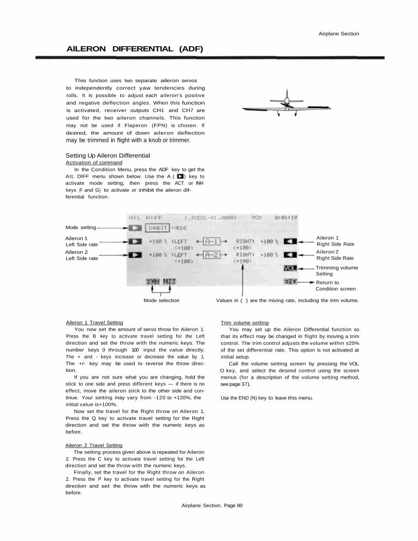
V-TAIL (VTL)
This function automatically sets up the PCM
1024Z to control a V-tail airplane with combined
elevator and rudder functions. It requires two
servos, one hooked up to receiver output CH2
(elevator 2/rudder) and the second plugged into
CH4 (elevator 2/rudder 1). The elevator and rud-
der deflection can be adjusted independently.
Setting Up V-Tail MixingActivation of command
In the Condition Menu, press the VTL key to get theV-TAIL Mixing menu shown below. Use the A keyto activate mode setting, then press the ACT or INHkeys ( F and G) to activate or inhibit V-Tail Mixing.
Mode setting
Elevator 1deflection angle
Rudder 1deflection angle
Elevator 2deflection angle
Rudder 2deflection angle
Return tocondition screen
Mode selection
Setting the Elevator Rates - 1 and 2You now set the rate for Elevator 1. Press the B key
to activate rate setting for Elevator 1 and set the rate withthe numeric keys E to M . The number keys 0 through100 input the value directly. The + and - keys in-crease or decrease the value by 1. The +/- key may beused to reverse the throw direction.
If you are not sure what you are changing, hold thestick to one side and press different keys — if there is noeffect, move the elevator stick to the other side and con-tinue. Your setting may vary from —100 to +100%, theinitial value is +50%.
Now set the rate for Elevator 2. Press the Q key toactivate Elevator 2 rate setting and set the rate with thenumeric keys as before.
Setting the Rudder Rates - 1 and 2You now set the rate for Rudder 1. Press the C key to
activate rate setting for Rudder 1 and set the rate with thenumeric keys E to M as before.
If you are not sure what you are changing, hold therudder stick to one side and press different keys — if thereis no effect, move the rudder stick to the other side andcontinue. The initial value is +50%, but your setting mayvary from -100 to +100%.
Now set the rate for Rudder 2. Press the P key toactivate Rudder 2 rate setting and set the rate with thenumeric keys as before.
Checking Your WorkAfter you have set up the V-Tail rates, be sure that
they move the correct directions. For up elevator com-mand, both V-tails should move upward. For right ruddercommand, the trailing edge of both surfaces should moveto the right. If they do not, use the +/- to reverse thedirection as needed.
Use the END ( N) key to leave this menu.
Airplane Section, Page 82

Airplane Section
RUDDER—AILERON (R->A)
Rudder to aileron coupling may be used for
correcting unwanted tendencies with aerobatic
planes. For example, this mixing can be used to
cancel out any rolling that occurs during knife
edge flight. The rates for left and right rudder
travel can be set independently. Mixing can be set
to be turned on and off during flight by setting a
switch (if no ON/OFF switch is set, mixing re-
mains on all the time).
Setting Up Rudder-Aileron MixingActivation of command
In the Condition Menu, press the A->R key to get theRUD TO AIL mixing menu shown below. Use the Akey to activate mode setting, then press the ACTor INH keys (F and G ) to activate or inhibit rudder-to-aileron coupling.
Mode setting
Mixing ratesetting
ON/OFF switchsetting
Return toCondition screen
Left
Right
Mode selection
Setting the Mixing Ratio - Left and RightYou now set the amount of mixing for Left rudder
command. Press the C key to activate mixing ratio forthe Left direction and set the value with the numeric keysE to M The number keys 0 through 100 input thevalue directly. The + and - keys increase or decreasethe value by 1. The +/- key may be used to reverse thethrow direction.
If you are not sure what you are changing, hold thestick to one side and press different keys — if there is noeffect, move the rudder stick to the other side and con-tinue. Your setting may vary from -100 to +100%, theinitial value is -50%.
Now set the amount of mixing for the Right ruddercommand. Press the D key to activate mixing ratio forthe Right direction and set the throw with the numerickeys as before.
On/Off Switch SettingOn initial setting, an activation switch for rudder to
aileron coupling is not set, meaning that once activated, itis on all the time. If you would like to set a switch to turnit on and off , call the Switch Setting screen by pressingthe SWT P key. Then use the keys to choose thedesired switch location and on direction. For more infor-mation on the switch setting method, see page 37).
Use the END (N) key to leave this menu.
Airplane Section, Page 83

Airplane Section
ELEVONS (EVN)
This function may be used to set up the con-
trols for delta wings, flying wings, and other tail-
less aircraft which need combined aileron and
elevator functions. Receiver CH1 and CH2 are
made the operating channels for the two elevons,
and differential operation is possible.
The elevator deflection angle and operating
direction can be set for each servo. For conve-
nience, the elevon deflection angles can be trim-
med in flight when a volume-setting lever is acti-
vated (this setting is performed by the aileron
differential ADF function on page 125).
Setting Up Elevon MixingActivation of command
In the Condition Menu. press the EVN key to getthe ELEVON Mixing menu as shown below. Use the Akey to activate mode setting, then press the ACTor INH keys ( F and G ) to activate or inhibit ElevonMixing.
Delta-Wing Aircraft
Elevons
Mode setting
Aileron 1 leftside rate
Aileron 2 leftside rate
Elevator 2 rate
Aileron 1 rightside rate
Aileron 2 rightside rate
Elevator 1 rate
Return tocondition menu
Mode Activation
Setting the Aileron 1 RatesYou now set the left-side rate for Aileron 1. Press the
B key to activate left rate setting for Aileron 1 and setthe rate with the numeric keys E to M . The numberkeys 0 through 100 input the value directly. The +and - keys increase or decrease the value by 1. The+/- key may be used to reverse the throw direction.
If you are not sure what you are changing, hold thestick to one side and press different keys — if there is noeffect, move the aileron stick to the other side and con-tinue. Your setting may vary from —120 to +120%, theinitial value is +100%.
Now set the right-side rate for Aileron 1. Press theQkey to activate Aileron 1 right rate setting and set the ratewith the numeric keys as before.
Setting the Aileron 2 RatesThis procedure is repeated for Aileron 2. Press theC
key to activate left rate setting for Aileron 2 and set therate with the numeric keys E to M as before.
Now set the right-side rate for Aileron 2. Press theP key to activate Aileron 2 right rate setting and set therate as before.
Setting the Elevator Rates — 1 and 2You now set the rate for Elevator 2. Press the D key
to activate rate setting for Elevator 2 and set the rate withthe numeric keys E toM .
Now set the rate for Elevator 1. Press the O key toactivate Elevator 1 rate setting and set its rate with thenumeric keys.
Checking Your WorkAfter you have set up the Elevon rates, be sure that
they move the correct directions. For up elevator com-mand, both elevons should move upward. For rightaileron command, the trailing edge of the right-handsurface should move up, and the trailing edge of the left-hand surface should move down. If they do not, use the+/- to reverse the direction as needed.
Use the END ( N ) key to leave this menu.
Airplane Section, Page 84
Airplane Section
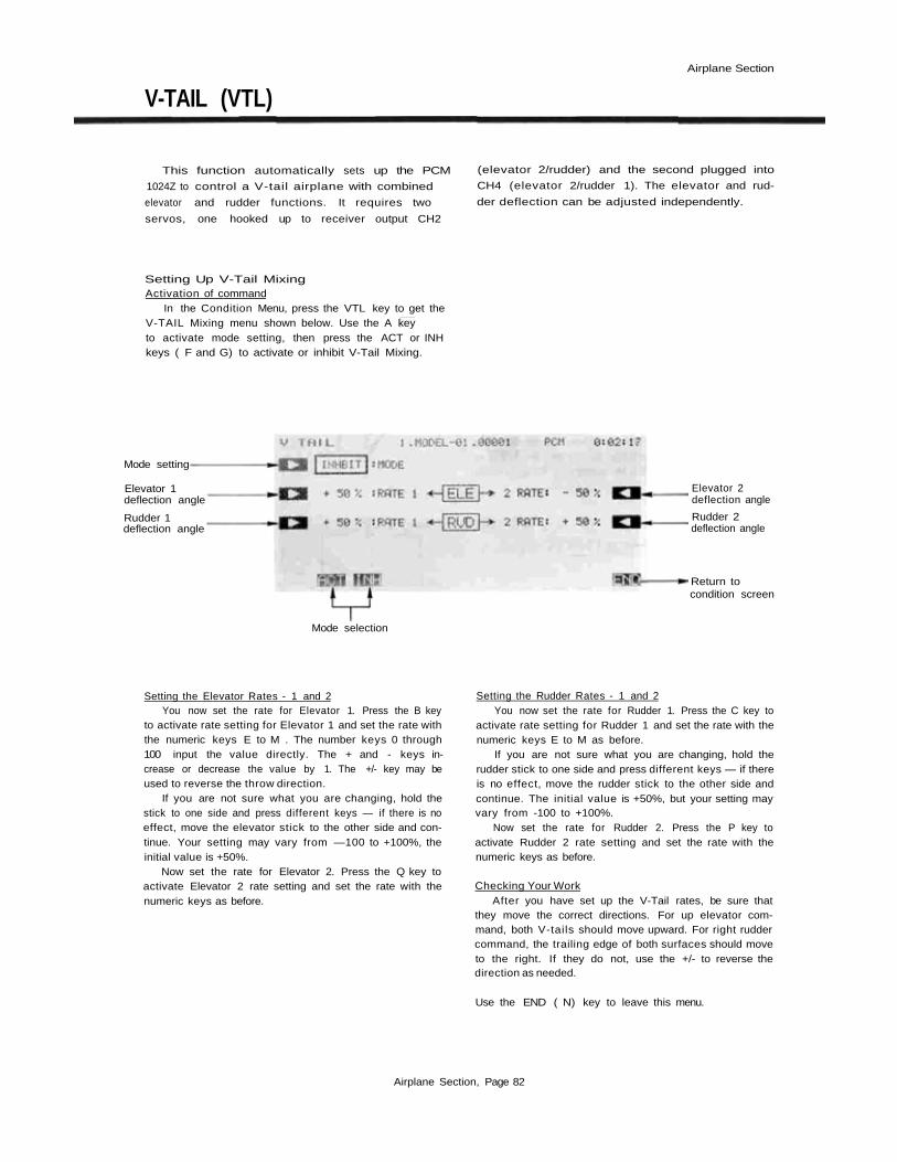
ELEVATOR- FLAP (E-F)
This mixing is used to droop the flaps whenever
an up elevator command is given (and may be set
up for down elevator as well, helpful during
'outside' maneuvers). It helps to eliminate 'buck-
ing,' and makes tight, square corners in maneuvers
for acrobatic aircraft.
Elevator-to-flap mixing can be set up to be
turned on and off during flight by a switch (if no
switch is activated, this mixing remains on all the
time). You can also set the flap trim rate in this
function. If the flaperon function is activated, the
elevators are mixed with the ailerons, otherwise,
the mixing is with the flaps only.
Setting Up Elevator-to-Flap MixingActivation of command
In the Condition Menu, press the E->F key to get theELE TO FPR menu shown below. Use the A keyto activate mode setting, then press the ACT or INHkeys ( F and G) to activate or inhibit Elevator-to-Flap.
ON/OFF switchsetting
Return toCondition screen
Mode setting
Flap trim rate
Down side
Up side
Mixingratesetting
Mode Selection
Setting the Mixing Ratio — Down and Up SideYou now set the amount of mixing for down elevator
command. Press the C key to activate mixing ratio forthe Down direction and set the value with the numerickeys E to M The number keys 0 through 100 inputthe value directly. The + and - keys increase or de-crease the value by 1. The +/- key may be used toreverse the throw direction. Your setting may vary from-100 to +100%, the initial value is set to +50%.
Now set the amount of mixing for the up elevatorcommand. Press the D key to activate mixing ratio forthe Up direction and set the throw with the numeric keysas before.
Flap Trim Rate SettingYou may choose any value for the Flap Trim Rate.
Knob (A) is used to trim the position of the flap servo,and the trim value controls the authority of the knob.The authority may be set anywhere from 0% to 100%,and the initial setting is 30%.
Call the flap trim setting screen by pressing the TRIMRATE B key, and select the desired trim rate using thescreen menus. You may want a small number for this rate,so that an accidental movement of the knob doesn't give alarge flap deflection.
On/Off Switch SettingOn initial setting, the activation switch for Elevator-to-
Flap mixing is set as SW (C) on at the upper position. Ifyou would like to change the switch or turn mixing on allthe time, call the Switch Setting screen by pressing theSWT P key. Then use the keys to choose the desiredswitch location and on direction. For more informationon the switch setting method, see page 37).
Use the END ( N ) key to leave this menu.
Airplane Section, Page 85
Airplane Section
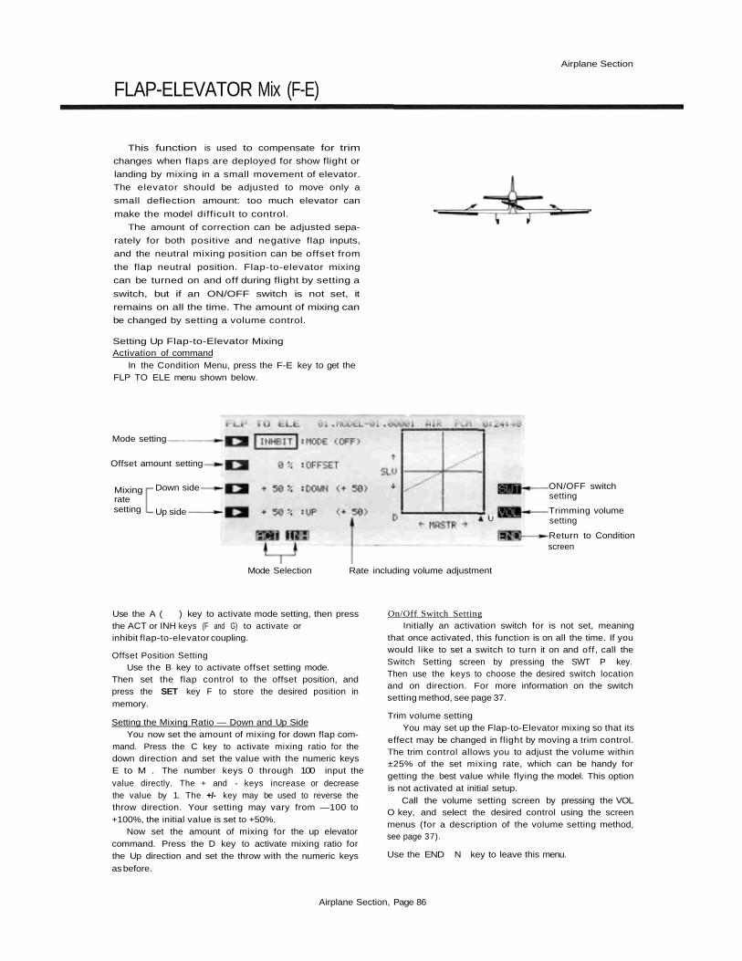
FLAP-ELEVATOR Mix (F-E)
This function is used to compensate for trim
changes when flaps are deployed for show flight or
landing by mixing in a small movement of elevator.
The elevator should be adjusted to move only a
small deflection amount: too much elevator can
make the model difficult to control.
The amount of correction can be adjusted sepa-
rately for both positive and negative flap inputs,
and the neutral mixing position can be offset from
the flap neutral position. Flap-to-elevator mixing
can be turned on and off during flight by setting a
switch, but if an ON/OFF switch is not set, it
remains on all the time. The amount of mixing can
be changed by setting a volume control.
Setting Up Flap-to-Elevator MixingActivation of command
In the Condition Menu, press the F-E key to get theFLP TO ELE menu shown below.
Mode setting
Offset amount setting
Mixingratesetting
U
ON/OFF switchsetting
Trimming volumesetting
Return to Conditionscreen
Down side
Up side
Mode Selection Rate including volume adjustment
Use the A ( ) key to activate mode setting, then pressthe ACT or INH keys (F and G) to activate orinhibit flap-to-elevator coupling.
Offset Position SettingUse the B key to activate offset setting mode.
Then set the flap control to the offset position, andpress the SET key F to store the desired position inmemory.
Setting the Mixing Ratio — Down and Up SideYou now set the amount of mixing for down flap com-
mand. Press the C key to activate mixing ratio for thedown direction and set the value with the numeric keysE to M . The number keys 0 through 100 input the
value directly. The + and - keys increase or decreasethe value by 1. The +/- key may be used to reverse thethrow direction. Your setting may vary from —100 to+100%, the initial value is set to +50%.
Now set the amount of mixing for the up elevatorcommand. Press the D key to activate mixing ratio forthe Up direction and set the throw with the numeric keysas before.
On/Off Switch SettingInitially an activation switch for is not set, meaning
that once activated, this function is on all the time. If youwould like to set a switch to turn it on and off, call theSwitch Setting screen by pressing the SWT P key.Then use the keys to choose the desired switch locationand on direction. For more information on the switchsetting method, see page 37.
Trim volume settingYou may set up the Flap-to-Elevator mixing so that its
effect may be changed in flight by moving a trim control.The trim control allows you to adjust the volume within±25% of the set mixing rate, which can be handy forgetting the best value while flying the model. This optionis not activated at initial setup.
Call the volume setting screen by pressing the VOLO key, and select the desired control using the screenmenus (for a description of the volume setting method,see page 37).
Use the END N key to leave this menu.
Airplane Section, Page 86

COLLECTIVE PITCH FUNCTION (CPT)(DIVING AIR BRAKE, HIGH PITCH TRIM)
Airplane Section
This function allows diving airbrake ("minus
pitch") adjustment at low throttle and high pitch
adjustment at high throttle for consistent model
speed during vertical aerobatics. This mixing can
be turned on and off during flight with a switch.
Air brake, engine idle-up trim, and the high-side
pitch control trim can be set independently. The
mixing switching point (minus pitch/high pitch
switching point) can be set at a selected throttle
stick position, and each trim rate can be adjusted.
The throttle delay when switching from minus
pitch to high pitch and the pitch delay when
switching from high pitch to minus pitch can also
be adjusted independently.
Setting Up Collective Pitch FunctionActivation of command
In the Condition Menu, press the CPT key to get theCOL PITCH menu shown below. Use the Akey to activate mode setting, then press the ACT orINH keys ( F and G ) to activate or inhibit the func-tion.
Mode setting
Idle-up
High pitch
Trim Rate setting
ON/OFF switchsetting
Trimming volumesetting
Throttle delaysetting
Pitch delaysettingReturn toCondition screen
Mixing operationpoint setting
Mode selection
Switch Point SettingPress the B key to enter the throttle position setting
function. Then set the throttle stick to the desired switch
point, and press the SET (F) key.
Idle-up Trim and Delay SettingPress the C key to enter the Idle-Up Trim rate setting
function, and set the rate with the numeric keys F toM. The range may be set from 0 to 100%, and the initialvalue is set to 0%.
Next, press the P key to enter the Throttle delaysetting function, and set the delay with the numeric keys.The setting range is 0 to 100%, and the initial value is set
to0%.
Pitch Control Trim Rate and Delay SettingPress the D key to enter the Pitch Trim Rate setting
function. Set the desired rate with the numeric keys F toM. The range may be set from 0 to 100%, and the initialvalue is set to 50%.
Press the O key to activate the Pitch Delay settingmenu, and set the delay with the numeric keys F to M .The range may be set from 0 to 100% (initial setting is
0%).
On/Off Switch SettingOn initial setting, the activation switch for the Collec-
tive Pitch function is set as SW (E) ON at the lower posi-tion. If you would like to change the switch or turnmixing on all the time, call the Switch Setting screen bypressing the SWT (R) key. Then use the keys tochoose the desired switch location and on direction. Formore information on the switch setting method, see page37).
Idle-Up Trim/Pitch Control Trim SettingYou may set up the Collective Pitch function so that
its effect may be changed in flight by moving a trim con-trol. The trim control allows you to adjust the volume bymoving a slider. At initial setting, the left-side lever is setfor idle-up trim and the right-side lever is set for pitchcontrol trim.
Call the volume setting screen by pressing the VOLO key, and select the desired control using the screenmenus (for a description of the volume setting method,see page 37).
Use the END (N) key to leave this menu.
Airplane Section, Page 87

Airplane Section
AlLEVATORS/COMBINED AlLERONS & ELEVATORS (ALV)
This function allows you to hook up the eleva-
tor surface on each side of the airplane independ-
ently, so that they operate together (elevator
mode) and differentially (aileron mode). This
function, sometimes called "ailevators" (ALV) will
give aileron control even at low speeds, because
the propeller wash is always passing over the tail
surfaces and may be used for rolling commands.
This function requires two elevator servos con-
nected to receiver output channels 2 and 5. In this
manual (see diagram), the rear control surfaces are
referred to as Aileron 3 and Aileron 4. With this
function, all control deflections — left and right
ailerons, and elevator on both sides — can be
adjusted. You may even add differential to the rear
ailerons.
Setting Up Differential ElevatorsActivation of command
In the Condition Menu, press the ALV key to get theAILVATOR menu shown below. Use the A key toactivate mode setting, then press the ACT or INHkeys (F and G) to activate or inhibit the function.
Mode setting
Aileron 3 Left.Side Rate
Aileron 4 LeftSide Rate
Elevator 1 RateSetting
Aileron 3 RightSide Rate
Aileron 4 RightSide Rate
Elevator 2 RateSetting
Return tocondition menu
Mode Activation
Setting the Aileron 3 RatesYou now set the left-side travel for Aileron 3. Press the
B key to activate left rate setting for Aileron 3 and setthe rate with the numeric keys E to M . The numberkeys 0 through 100 input the value directly. The +and - keys increase or decrease the value by 1. The+/- key may be used to reverse the throw direction.
Your setting may vary from -100 to +100%,the initialvalue is-50%.
Now set the right-side rate for Aileron 3. Press the Qkey to activate Aileron 3 right rate setting and set the ratewith the numeric keys as before.
Setting the Aileron 4 RatesThis procedure is repeated for Aileron 4. Press the C
key to activate left rate setting for Aileron 4 and set therate with the numeric keys E to M as before. The maxvalues and initial setting are the same as for Aileron 3.
Now set the right-side rate for Aileron 4. Press the 13key to activate Aileron 4 right rate setting and set the rateas before.
Setting the Elevator Rates - 1 and 2You now set the rate for Elevator 1. press the D key
to activate rate setting for Elevator 1 and set the rate withthe numeric keys E to M . The initial rate is 100%, butyou may vary your setting between -100 and +100%.
Now set the rate for Elevator 2. Press the O key toactivate Elevator 2 rate setting and set its rate with thenumeric keys. Settings have the same range as Elevator 1.
Checking Your WorkAfter you have set up the Ailevator rates, be sure that
they move the correct directions. For up elevator com-mand, both elevators should move upward. For rightaileron command, the trailing edge of the right-handsurface should move up. and the trailing edge of the left-hand surface should move down. If they do not, use the+/- to reverse the direction as needed. Adjust thetravels on either side to get the differential effect, if youwish.
ExitingUse the END ( N) key to leave this menu.
Airplane Section, Page 88

Airplane Section
FLAPERONS (FPN)
This function allows you to program the
ailerons to work in the same direction, giving a
flap response as well as aileron control (see figure).
For good square maneuvers, and landing, both
ailerons can be raised and lowered simultaneously.
While this function is on, regular aileron operation
is always present.
The Flaperon function requires two separate
channels: Receiver CH1 (aileron 1/flap 2) and CH6
(aileron 2/flap 1) are the operating channels. The
Aileron 1 and Aileron 2 left and right deflection
angles can be adjusted independently, making it
easy to apply differential to the ailerons. With
differential, the up side travel is set to around 5%
larger than the down travel.
You may also adjust the Flap 1 and Flap 2
throws independently, and you can set the flap
trim rate as large or small as you like. Also, the
flap trim offset can be adjusted, allowing you to
freely change the flap neutral angle.
Aileron operation
Flap operation
Setting Up FlaperonsActivation of command
In the Condition Menu, press the FLP key to get theFLAPERON menu as shown below. Use the A keyto activate mode setting, then press the ACT or INHkeys (F and G) to activate or inhibit the function.
Mode setting
Aileron 1 LeftSide Travel
Aileron 2 LeftSide Travel
Flap 2 TravelSetting
To Next Screen
Aileron 1 RightSide Travel
Aileron 2 RightSide Travel
Flap 1 TravelSetting
Return tocondition menu
Mode Selection
Setting the Aileron 1 TravelYou now set the left-side travel for Aileron 1. Press the
B key to activate left travel setting for Aileron 1 and setthe travel with the numeric keys E to M . The numberkeys 0 through 100 input the value directly. The +and - keys increase or decrease the value by 1. The+/- key may be used to reverse the throw direction.
If you are not sure what you are changing, hold thestick to one side and press different keys — if there is noeffect, move the aileron stick to the other side and con-tinue. Your setting may vary from —120 to +120%, withan initial value of +100%.
Now set the right-side travel for Aileron 1. Press theQ key to activate Aileron 1 right travel setting and setthe travel with the numeric keys as before.
Setting the Aileron 2 TravelsThis procedure is repeated for Aileron 2. Press theC
key to activate left travel setting for Aileron 2 and set thetravel with the numeric keys Eto M as before.
Now set the right-side travel for Aileron 2. Press theP key to activate Aileron 2 right travel setting and setthe travel as before.
Setting the Flap Travels — 1 and 2You now set the travel for Flap 2. Press the D key to
activate travel setting for Flap 2 and set the travel withthe numeric keys E to M . Your setting may vary from-100 to +100%, with an initial value of +100%.
Now set the travel for Flap 1. Press the O key toactivate Flap 1 travel setting and set its travel with thenumeric keys. Its initial value is -100%.
Airplane Section, Page 89

Airplane Section
Flap Trim Authority SettingIn the Flaperon mode. Flap Trim moves both ailerons
upwards or downwards together. To input the Flap TrimAuthority, move to the next screen by pressing the NXTR key. Then press the D key and set the rate with thenumeric keys F to M. You may choose any value from0% to 100% for the Flap Trim Authority. The initialsetting is 30%, but a smaller number is recommended.
Flap Trim Offset SettingFlap trim offset sets the flap position from which
motion occurs. To input the flap trim offset amountsetting, press the B key, then set the flap trimmer to theposition to be set and press the SET F key. The offsetcan be anywhere between ±(trim authority setting).
Checking Your WorkAfter you have set up everything, be sure the controls
move the correct directions. If they do not, use the +/-to reverse the direction as needed.
Use the END ( N) key to leave this menu, or hit PREto get to the previous menu.
Airplane Section, Page 90

Airplane Section
AIRBRAKE (ABK)
Airbrake presets are used to set up preset
deflections of the elevators, flaps, and (optionally)
spoilers for landing precision or for constant speed
during vertical flight maneuvers. Airbrake presets
can be turned on and off during flight by ON/OFF
switch, or you may define an AUTO mode where
mixing is turned on and off automatically by
throttle stick position.
The AUTO mode, if used, may be turned on
and off with a switch. However, a command on
the air brake has priority and is followed regardless
of the position of the AUTO mode ON/OFF
switch.
Suggested settings for the Airbrake function are
a flap deflection of +50%. The elevators will need
to be set to about -20 to 23%. Of course, the
elevators should be adjusted so that the model
maintains level flight when the Airbrake function
is operated.
Setting Up The Airbrake PresetsActivation of command
In the Condition Menu, press the ABK key to get theAIR BRAKE menu as shown below.
Mode setting
Flap PresetPosition Setting
Elevator PresetPosition Setting
Flap Trim RateSetting
Spoiler Setting
Air brake ON/OFFSwitch Setting
Return tocondition menu
Airbrake Mode Selection
Use the A key to activate mode setting, andpress the ACT F key to activate the function. Nowyou must decide on Manual or Auto operation. Select themanual mode by pressing the MAN ( G) key. Select theauto mode by pressing the AUT H key.
Throttle Position Setting (Auto Mode Only)For the Auto mode, you need to input the position at
which the function will take effect. Press the B key, thenmove the throttle stick to the desired position, and pressthe SET ( F ) key to memorize the position.
Flap Preset Position SettingTo set the position that the flaps will move to, press
the C key and use the rate setting keys E to M . Thissetting may vary from -100 to 100%, and is initially setto 50%.
Elevator Preset Position SettingTo set the position that the elevators will move to,
press the D key and use the rate setting keys E to M .This setting may vary from -100 to 100%, and is initiallyset to -30% by the system.
Flap Trim Authority SettingFlap Trim moves both ailerons upwards or downwards
together. To input the Flap Trim Authority, press theNXT R key. Then set the rate with the numeric keysE to M. You may choose any value from 0% to 100%for the Flap Trim Authority. The initial setting is 30%,but a smaller number is recommended. If you input anumber here, it will override whatever value was input inthe Flaperon menu.
Airplane Section, Page 91

Airplane Section
Spoiler setting: Press the SPO Q key to get to themenu below.
Spoiler Activate
Spoiler PresetSetting
To PrecedingScreen
Spoiler Mode Selection
Use the A () key to activate mode setting, thenpress the ACT or INH keys ( F and G) to activateor inhibit the function. Press the B key and set the ratewith the numeric keys E to M . The initial spoiler presetis 50%, but you may set it between -100 and +100%.Return to preceding screen by pressing the Q key.
Airbrake ON/OFF Switch DefinitionSW (C) is turned ON at the lower position at initial
setting. If you'd like another switch, call the switchsetting menu by pressing the SWT P key. For a de-scription of the switch setting method, see page 37.Caution: if the ON/OFF switch is disabled with NUL, theAirbrake function remains on all the time.
Auto ON/OFF Airbrake Switch Definition (AUTO modeonly)
At first setting, the automatic airbrake control switchis defined as SW (E), ON at the lower position. To changethis, call the switch setting menu by pressing the SWTO key. For a description of the switch setting method,
seepage37.
Use the END N key to exit this menu.
Airplane Section, Page 92

Airplane Section
SNAP ROLL (SIMP)
Your PCM 1024Z system may be programmed
to perform snap rolls by flipping a switch. Four
snap roll directions can be defined, and the preset
positions of the aileron, elevator, and rudder
servos can be set for each one.
You may activate a safety switch to ensure that
snap rolls are not accidentally commanded while
the landing gear is down, even if the snap roll
switch is turned on accidentally.
Setting Up The Snap Roll PresetsActivation of command
In the Condition Menu, press the SNP key to get theSNAP ROLL menu as shown below.
Snap Roll Directions Direction Switches
(Note: These snap roll direction setting switches are only present on the T9ZAP systems, not on the T9ZHP)
Mode setting
Ratesetting
-Throw setting
ON/OFF switchsetting
Safety switch setting
Return to conditionmenu
Mode selection
Use the A key to activate mode setting, thenpress the ACT or INH keys ( F and G ) to activateor inhibit the function.
Inputting the Snap Roll Preset Control PositionsWe'll start with the 1-2 direction (Right/Up) snap
roll setting. Press the R key to get to the setting menu,then press the 1-2 F key.
To set the Aileron servo throw setting, press theBkey. Use the numeric keys E to M to input the desiredpreset condition. The default is +100%, but you may useanything between -110 and +110%.
Now we'll set the Elevator servo preset. Press the Ckey. and set the preset with the numeric keys E to M .This also has a default of +100%, but you may use any-thing between -110 and +110%.
The last part of the setting is for the rudder position.Press the D key, and enter the rate that you want therudder to move with the numeric keys E to M. Thissetting also has a default of +100%, and may be set any-where between -110 and +110%.
This procedure should be repeated for the 1-1direction (Rright/Down) snap roll setting, 2-2 direction
(Left/Up) snap roll setting, and 2-1 direction (Left/Down) snap roll setting.
Snap Roll Switch ON/OFF DefinitionSW (H) is defined to be the Snap Roll switch, and is
turned ON at the forward position at initial setting. Ifyou'd like another switch, call the switch setting menu bypressing the SWT P key. For a description of theswitch setting method, see page 37. Caution: if you definea switch that doesn't have a spring return, the Snap Rollfunction will remain on all the time!
Snap Roll Safety switch settingA safety switch should be used to prevent accidental
operation of the snap roll function. To examine the snaproll safety switch settings, call up the switch setting screenby pressing the SWT O key. The function initiallydefines SW (F) for Mode I, (G) for Mode II to be thesafety switch. You should set the ON direction of thesafety switch to match the landing gear switch positionwhen the landing gear is down. When this switch is ON,the snap roll function is inhibited.
Use the END N key to exit this menu.
Airplane Section, Page 93

Airplane Section
THROTTLE CURVE ADJ. (TCV)
This function programs throttle curves for dif-
ferent flight modes. The throttle curve sets the
servo response over full stroke of the throttle stick
by a 13-point curve. The low side rate can be ad-
justed with a volume control (point 7 is the refer-
Setting Up The Throttle Curve FunctionThrottle Curve Inputting
In the Condition Menu, press the TCV key to getthe THR CURVE menu shown in the figure below.
ence). The servo delay at flight condition switching
can also be programmed. You need to activate the
Model menu throttle curve [THR] function (page
53) to allow the Throttle curve function to work
properly.
Curve setting
Low SideRate Setting
Point Movement
Trim VolumeSetting
Return ToCondition Menu
Low Side Rate Set Value, Including Trim Volume
Setting Point Selection (Points 1 to 13)Press the Bkey to turn on the curve inputting
function. Use the movement keys Q and R to select thepoint whose value is to be set. The PT-> key increasesthe point number by one, and the <-PT key reduces thepoint number by one. The active point on the curve isshown as a black dot.
Once you have selected the desired point on the curve,you may input the rate with the rate setting keys E toM. The number keys 0 through 100 input the valuedirectly. The + and - keys increase or decrease thevalue by 0.5 with each button pressing (so it takes twohits to see a number change because of numeric round-ing).
You may set or reset each point on the curve byrepeating these steps for each point.
Low-Side Volume Control AssignmentNo volume controller is defined when TCV is first
activated. To set the control and direction of the volumeadjuster, call the volume setting screen by pressing theVOL O key. Use the buttons to select the control anddirection you desire. For a description of the volumesetting method, see page 37.
Use the PRE N key to return to the previous menu,or use the END N key to leave this menu and returnto the Condition menu.
Curve Setting NoteIf you change Point 7 after setting the low side rate,
other points in the throttle curve also change, becausePoint 7 is the reference point for the curve.
Low-Side Rate AdjustmentPress the D key and you may input the rate with the
numeric keys E to M . You may set anywhere in therange from 0 to 110% (initially the rate is set to 100%).
Airplane Section, Page 94

Helicopter Section
HELICOPTER SECTION
This section contains information on the commands that apply to
helicopters only. Each of these functions can be set independently for
different flight conditions.
To get to these settings, press the MDL key from any menu in a
Helicopter setup. To select one, first select the line containing the
desired function with the B , C, or D keys. Then use the F to
L keys to select the function to be entered.
For conditions that apply to all models (ATV, AFR, D/R, PMX,
STM, TOF, CNA, and TRM functions), refer to the Common Condi-
tions section. For instructions on Airplanes and Sailplanes, refer to
the sections pertaining to those aircraft.
Select DesiredLine WithThese Keys
To Home Screen
To System Menu
To Model Menu
Function Selection Keys Activates Condition Hold Function
Helicopter Section Table of ContentsHelicopter Transmitter Controls and Functions. . . . . . . . . . . . . . . . . 96Helicopter Receiver and Servo Connections. . . . . . . . . . . . . . . . . . . 98Helicopter Setup Example. . . . . . . . . . . . . . . . . . . . . . . . . . . . . 99Specific Control Setup DefinitionsPCV. . . .Pitch Curve . . . . . . . . . . .Adjusts response in different . . . 104
flight conditions
PHV . . .Hovering Pitch. . . . . . . . . .Used to trim pitch response . . . . 105around hover
PTM . . .Pitch Trim . . . . . . . . . . . .Allows pitch trim offset . . . . . . 106without changing curve
TCV . . .Throttle Curve. . . . . . . . . .Program the shape of the. . . . . . 107throttle response
THV . . .Hovering Throttle. . . . . . . .Can adjust throttle response. . . . 108around hover
HOF . . .Hovering Offset. . . . . . . . .Programs pitch mix hovering . . . 109point
HLD . ..Throttle Hold . . . . . . .Moves the throttle to idle . . . . . 110during autorotation
SWP. . . .Swashplate Type . . . . . . . .Compensates for power loss when 111cyclic applied
P->R . . .Pitch-> Rudder . . . . . . . . .Handles torque changes from . . . 112pitch angle inputs
R->T . . .Rudder -> Throttle . . . . . . .Accounts for power change due. . . . 1 1 3to rudder
GYR . . .Gyro Sensitivity. . . . . . . . .Used to switch gyro sensitivity . . 114ACC . . .Acceleration. . . . . . . . . . .Cancels torque due to sudden . . . 116
throttle commandsINV. . . .Inverted Pitch . . . . . . . Sets pitch rates for inverted . . . . 117
flight
Helicopter Section, Page 95

Helicopter Section
HELICOPTER TRANSMITTER CONTROLS AND FUNCTIONS
Functions and locations given in this drawing arethe factory default positions, which occur uponstartup. Each setting can be easily changed as theowner desires. The Function Change menu [FNC]may be used for this purpose.
Helicopter Section, Page 96

Helicopter Section
Note that all stick & switch positions may bechanged
1. Aileron control2. Throttle control . . . (MODE II)
Elevator control . . . (MODE I)3. Elevator control . . . (MODE II)
Throttle control . . . (MODE I)4. Rudder control5. CH 5 switch
Rate gyro output switching/inverted switch.6. Hovering rate lever (CH6)
Adjusts the hovering point pitchindependently from the throttle. Used inpitch trimming when hovering. When thethrottle stick is at the SLOW or HIGH side,the pitch servo does not operate even if thislever is moved.
7. CH7/pitch trim knobUsed as a spare channel, or as the pitchtrimmer.
8. CH8 switchUsed as a spare channel (3 positions).
9. Aileron trim lever trims the ailerons.10. Elevator trim lever trims the elevators.11. Throttle trim lever (with ATL) Adjustable
throttle limiter type trim lever. Operates atthe throttle stick SLOW side. Movement ismaximum at maximum slow. Since the HIGHside does not change even if the SLOW side isadjusted, it is very convenient whenconnecting the linkage, etc.
12. Rudder trim lever trims the rudder.13. Pitch control HIGH side trim lever.
Pitch control servo HIGH pitch trimmer.Adjusted for optimum pitch during flight.
14. Aileron dual rate switch.Aileron deflection angle switch.
15. Elevator dual rate switch.Elevator deflection angle switch.
16. Rudder dual rate switch.Rudder deflection angle switch.Can also be used as the CH9 switch.
17. Normal/idle-up 1/idle-up 2 switch.Idle-up ON/OFF switch.The On direction is set by condition select(CSL) function (page 40).(Flight condition switch.)
18. Throttle hold switch.This switch is used during auto rotation.The ON direction is set by condition select(CSL) function (page 40).(Flight condition switch)
19. Trainer switch.This switch is turned on in the forwardposition. It is spring loaded and is turned offwhen released. It can also be changed to analternate switch (page 29).
Helicopter Section, Page 97
Helicopter Section
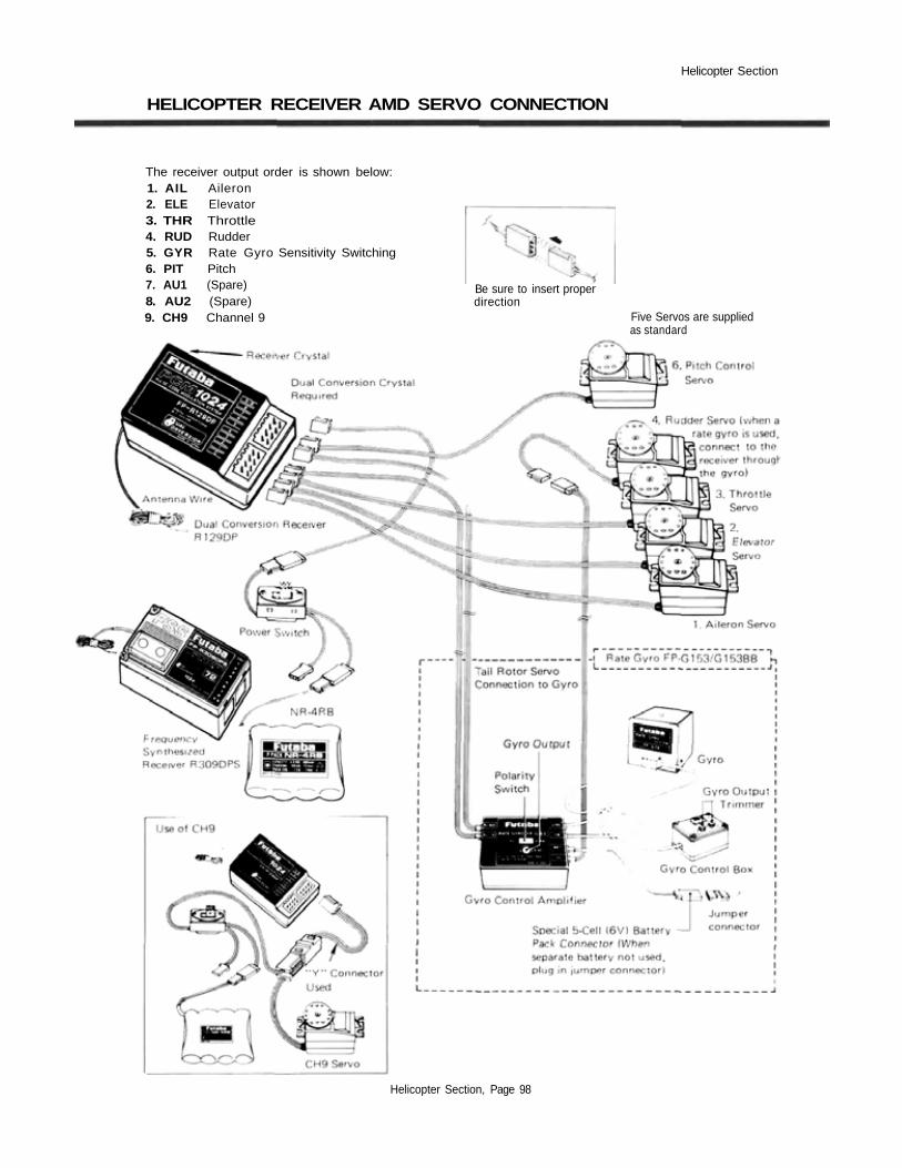
HELICOPTER RECEIVER AMD SERVO CONNECTION
The receiver output order is shown below:1. AIL Aileron2. ELE Elevator3. THR Throttle4. RUD Rudder5. GYR Rate Gyro Sensitivity Switching6. PIT Pitch7. AU1 (Spare)8. AU2 (Spare)9. CH9 Channel 9
Be sure to insert properdirection
Five Servos are suppliedas standard
Helicopter Section, Page 98

Helicopter Section
SAMPLE HELICOPTER SETUP INSTRUCTION
The following example shows how the PCM
1024ZH may be programmed for a contest heli-
copter model, although for completeness we have
added other functions (these will be marked by a
"t" sign). The settings presented here are for a
typical model. Your model's settings are likely to
vary from these, but the procedures given will still
be applicable.
1 Memory SelectionUse the Model Select function MSL to select amodel memory.
Choose the Helicopter Setup using the Type TYPfunction from Model menu.
2 Model NamingName the model using the Model Name MNA func-tion in the model menu. Note that the default flightcondition is named "NORML" (the condition nameis located next to the model name). The systemautomatically adds and names three other flightconditions, which you will program later in this
example.
3t Set Control OrderIf desired, reset the Control Order using the Func-tion Control FNC in the model menu. Here youmay choose what sticks, sliders, and trims controlthe different functions.
4 Hook Up ControlsHookup the aileron, elevator, throttle, and rudderservos in accordance with the model's instructionsor plans.
5 Plug Servos Into ReceiverPlug Servos into Correct Channel Numbers1 . . . .AIL . . . . .Aileron2 . . . .E LE. . . . .Elevator3 . . . .THR . . . .Throttle4 . . . .RUD . . . .Rudder5 . . . .GYR . . . .Rate Gyro Sensitivity6 . . . .PIT . . . . .Pitch7 . . . .AU1 . . . .(Spare)8 . . . .AU2 . . . .(Spare)9 . . . .CH9. . . . .Channel 9
6 Set Servo Throw DirectionCheck the proper direction of throw for each
servo. Use Reversing Function REV in the Modelmenu to set proper throw directions. Reverse chan-nels as necessary to correct throws. Link the carbu-retor to the throttle servo so that the carb may befully closed to shut off engine.
7 Flight Conditions SwitchingYou may set up the system to call up more than
one function or switch to a new set of trims or con-trol settings simultaneously by moving a singleswitch. This is very convenient for loading differentflight conditions such as Idle-up 1 IDL1 , Idle-up 2IDL2 , and Throttle Hold HOLD in addition to thenormal flight condition. You may change EVERYparameter between flight modes.
We recommend that you fly the model and adjusttrims and control responses to your liking beforedefining another flight condition. Then, as describedbelow, you will copy the set of adjustments to a newflight condition (this will maintain all trim settingsbetween the different conditions), and define thecondition switches that activate them. Each may bemodified for the new desired conditions, and youmay add new functions as necessary.
Use the Condition Select CSL button in theModel Menu. The four flight conditions listed abovehave already been allocated. The position and ONdirection of each flight condition call switch are setas follows:
1. Normal. . . . .Operation when. . . .Used in hovering,all switches OFF etc.
2. Idle-up 1 . . . .ON at SW (E) . . . . .For 540° stallCenter position turns, looping,
rolling stall turns
Helicopter Section. Page 99

Helicopter Section
3. Idle-up 2 . . . .ON at SW (E) . . . . .Used for rollingForward position aerobatics.
4. Throttle . . . .ON at SW (G) . . . . .Activate forHold Forward position autorotation.
In the case above, the flight condition priority is4>3>2>D, with 4 having the highest priority. Thismeans that if the Idle-Up 1 switch is on, and Throttlehold is turned on, the system will use the Throttlehold settings.
To set the condition data for each flight condi-tion, be sure that you call the appropriate conditionby turning on the correct switch (as given above).Read the condition name after the model name to besure you are changing the condition you want.
8 Normal Flight ProgramsSelect the Normal flight settings by turning off
all the flight condition switches.
9 Throttle Curve SettingCall the Throttle Curve THA function from the
Model Menu. Check to see that it is activated ACT .
Next, move to the condition menu and pressTCV to get the setting menu. Set the throttle curveto the values shown in the table below:
The throttle responds slowly at first and then theresponse rate increases at the top end.
10 Pitch Curve SettingCall the pitch curve PIT function from the
model menu. Verify that the PIT curve function isactivated ( ACT ) .
The following settings assume a semi-symmetricalrotor blade with no twist. For the pitch curve, theinitial LOW rate is 100% and the HIGH rate is 100%.Set the maximum pitch angle in advance. The pitchangle is -4° to +12°.
When setting the pitch angle, set the hoveringpitch lever and the HIGH side pitch lever to thecenter positions. These levers may be activated inflight to make adjustments. Next, input the data sothat the normal pitch used in hovering becomes-2.5° to+10° by LOW/HIGH side rate setting.
Although unimportant in calm conditions, thepitch angle should be set to that the High side pitchrate is large. This provides high collective sensitivityto help cope with windy conditions.
Pitch Curve Setting.Move to the Condition menu, and select the pitch
curve PCV key. Set the pitch curve to the follow-ing values:
Point
Setting (%)
1
9
2
18
3
27
4
35
5
43
6
52
7
59
8
67
9
73
10 11
78 82
11
86
13
88
The rise at the low end is fast, and then the riserate is reduced at the high end. We recommendsetting the hovering pitch to +4.5°.
11 Flight Condition CopyingUse the Condition Select CSL button in the
Model Menu. This function displays the flight condi-tions associated with the model in active memory.Note the condition number next to the D (default)in the display. This is the set of conditions associatedwith the trimmed model. Also note the three num-bers following: these are the conditions associatedwith Idle-up 1&2 and Throttle Hold, that will becopied into and modified.
Use the Copy Condition CPC from the Systemmenu. This function may be used to copy the con-
tents of one condition into another. Choose thedefault flight condition number (next to the D),press the SET button, then choose the Idle-up 1condition number in the lower box "TO CONDI-TION." Give the command to copy. Repeat forIdle-up 2 and Throttle-hold conditions.
Normal->-ldle-up 1Normal->ldle-up 1Normal->Throttle Hold
Helicopter Section, Page 100
Helicopter Section
12 Idle-Up 1 SettingThe switch that calls the Idle-up 1 conditions
(SW-E, center position) is not yet activated. In theModel menu, press the Condition Select CSL key,then select the condition position. Press the Switchbutton SWT , select SW-E (if it is not alreadyselected), and press the center position button ( Q).Hit the previous key PRE and END to finish.
Move the Idle-up 1 switch to its ON position andverify that the condition name after the model namerefers to Idle-up 1. Then you may go through theCondition menu items to revise the desired settingsin the new mode.
Throttle Curve Setting: move to the condition menuand press TCV to get the setting menu. Change thefirst seven Idle-up 1 throttle curve points to thevalues shown in the table below:
Pitch Curve Setting: Select the pitch curve PCVkey. The Normal curve copied already appears onthe screen. The Idle-up 1 pitch curve uses the samecurve as the normal condition, but the maximumHIGH side pitch angle should be 8° to 10°, depend-ing on the engine used. Set the pitch angle by curveor rate.
Idle-Up 2 Setting13Call up the Idle-up 2 conditions by setting SW-E
to the 1 (forward) position. Be sure that the switchis defined using CSL as in the previous case. Now,you may go through the menu items to revise thedesired settings in the new mode (be sure that thecondition name after the model name refers to Idle-up 2).Throttle Curve Setting: move to the condition menuand press TCV to get the setting menu. Change thefirst seven Idle-up 2 throttle curve points to thevalues shown in the table below:
Pitch Curve Setting: Select the pitch curve PCV
key. The Normal curve copied already appears onthe screen. Set the HIGH side pitch the same as Idle-up 1. Values may be easily compared by switchingbetween Idle-up 1 & 2 with the condition switch, sosettings may be easily matched. Set the LOW sidepitch curve to the following values:
Adjust the pitch curve low side to -4°
14 Throttle Hold SettingNow the Throttle Hold conditions are set for use
in autorotation. Call up the Throttle Hold condi-tions by setting SW-G to the 1 (forward) position.Now you will set the Throttle Hold ON/OFF switchso that SW (G) is turned on in the 1 (forward)position, the same as the flight condition call switch:
Call the Throttle Hold HLD function from the condition menu. Set the condition switch SW (G) to
the 1 (forward) position. Select the Manual modeMAN and activate the throttle hold function. Pressthe SWT button to get to the Switch menu, andactivate the SW (G)-1 position. Hit PRE and ENDto exit.
When SW (G) is in the 1 (forward) position, thethrottle hold function is turned on and when SW (G)is in the 2 (rear) position, the function is turned off.In throttle hold, set the throttle to move the servo toengine idle (approximately 15%).Pitch Curve Setting: Select the pitch curve PVC
key. The Normal curve copied already appears onthe screen. During autorotation. maximum pitch isused at both the HIGH and LOW sides. Therefore,normally set the HIGH and LOW rates to 100% each.The curve must be set so that the rise matches therotor near points 2 to 6. The rotor blade pitch angleis-4° to+12°.The pitch angle for each flight condition is shownbelow:
Normal ....... -2.5° ~ 4.5° ~ 10°Idle-up 1 . . . . . . . -2.5° ~ 4.5° ~ 8°Idle-up 2 . . . . . . . -4° ~ 4.5° ~ 8°Throttle Hold . . . . -4° ~ 4.5° ~ 12°
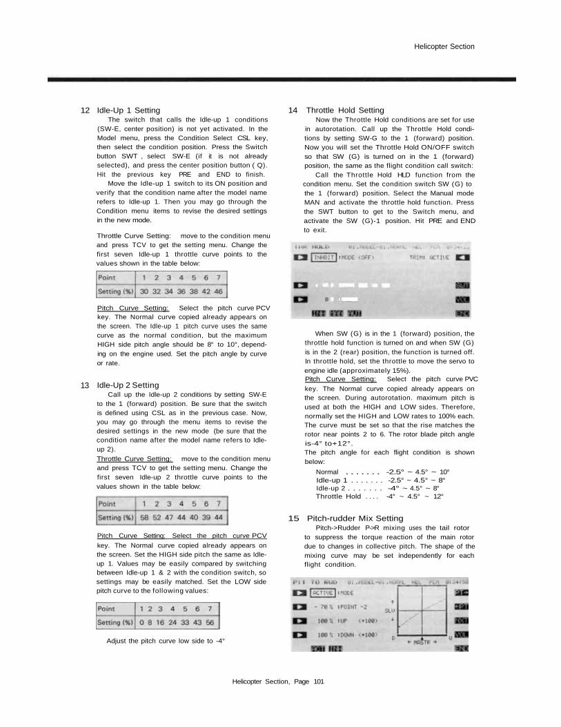
15 Pitch-rudder Mix SettingPitch->Rudder P->R mixing uses the tail rotor
to suppress the torque reaction of the main rotordue to changes in collective pitch. The shape of themixing curve may be set independently for eachflight condition.
Helicopter Section, Page 101

Helicopter Section
To set this feature, call the Pitch->R udder P->Rfrom the Condition Menu. The Normal setting isused during hover, so it should be set to match take-off, landing, and constant speed vertical climbing.
Normal Setting:Select the normal flight conditions by turning off
all the flight condition switches. Set the rudder mix-ing curve to the following values (initial settings):
17 Rudder->Throttle Mix SettingRudder->Throttle R->T mixing is effective in
hovering eight, nose in circle, top hat, pirouette, andother aerobatics. It should be set so that at half-throttle, if the rudder stick is operated, the rotorspeed is maintained to keep altitude constant.
Idle-up 1 Setting:These settings are used in 540° stall turns, loop-
ing, and rolling stall turns and is set to be straightahead when the model is pointing directly into oraway from the wind. Call the Idle-up 1 flight condi-tions by moving switch E to the 0 (center) position.Set the rudder mixing curve to the following values:
When these values are input, the rudder is offsetat the half-throttle position.
Idle-up 2 Setting:These settings are used in rolls. Activate the Idle-
up 2 flight conditions by moving switch E to the 1(forward) position. Set the rudder mixing curve tothe following values:
The rudder is offset at the half-throttle position.
Throttle Hold Setting:Throttle Hold settings are intended to keep the
model pointed straight ahead during linear autorota-tion. The tail rotor pitch angle is nearly 0°. Set theThrottle Hold flight conditions by moving switch Gto the 1 (forward) position. Set the rudder mixingcurve to the following values:
For normal models, commanding right ruddershould increase throttle slightly, while using leftrudder should decrease throttle slightly.
To set this feature, return to the Normal flightcondition. Press the Rudder->Throttle R->T fromthe Condition Menu. Press the ACT button to acti-vate it, and set the Left value to -10%, and theRight value to +10%.
18 Trim Offset SettingThe Trim Offset TOF setting should be adjust-
ed for Idle-up 1 and Idle-up 2. Aileron, elevator, andrudder are offset so that the model flies straightahead during normal flight.
Call the Idle-up 1 or 2 flight condition by settingSwitch E to the 0 (center) position. Press the TOFbutton from the Condition menu. Recommendedsettings for aileron and elevator offsets are 6% to10%. A delay can be set with the digital trim TRMfunction.
Rudder offset is set by the Pitch->Rudder func-tion set previously, so is not set here.
Delay SettingsSet the amount of delay for each flight condi-
tion. We recommend the following settings:Normal . . . . . . . 20%Idle-up 1 . . . . . . . 20%Idle-up 2 . . . . . . .20%Throttle Hold . . . . 60%The delay for Throttle hold should be large, be-
cause the rudder angle changes significantly duringflight condition changes.
Helicopter Section, Page 102
Helicopter Section
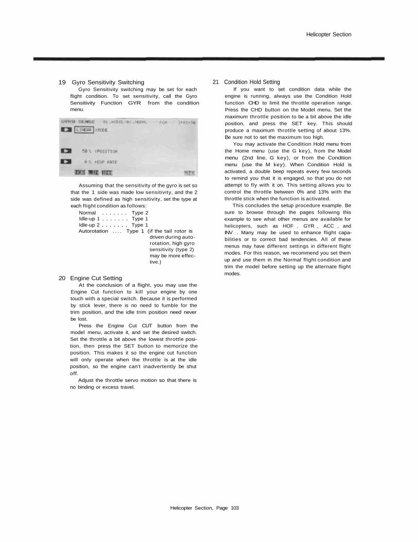
19 Gyro Sensitivity SwitchingGyro Sensitivity switching may be set for each
flight condition. To set sensitivity, call the GyroSensitivity Function GYR from the conditionmenu.
Assuming that the sensitivity of the gyro is set sothat the 1 side was made low sensitivity, and the 2side was defined as high sensitivity, set the type ateach flight condition as follows:
Normal . . . . . . . Type 2Idle-up 1 . . . . . . . Type 1Idle-up 2 . . . . . . . Type 1Autorotation . . . . Type 1 (if the tail rotor is
driven during auto-rotation, high gyrosensitivity (type 2)may be more effec-tive.)
20 Engine Cut SettingAt the conclusion of a flight, you may use the
Engine Cut function to kill your engine by onetouch with a special switch. Because it is performedby stick lever, there is no need to fumble for thetrim position, and the idle trim position need neverbe lost.
Press the Engine Cut CUT button from themodel menu, activate it, and set the desired switch.Set the throttle a bit above the lowest throttle posi-tion, then press the SET button to memorize theposition. This makes it so the engine cut functionwill only operate when the throttle is at the idleposition, so the engine can't inadvertently be shutoff.
Adjust the throttle servo motion so that there isno binding or excess travel.
21 Condition Hold SettingIf you want to set condition data while the
engine is running, always use the Condition Holdfunction CHD to limit the throttle operation range.Press the CHD button on the Model menu. Set themaximum throttle position to be a bit above the idleposition, and press the SET key. This shouldproduce a maximum throttle setting of about 13%.Be sure not to set the maximum too high.
You may activate the Condition Hold menu fromthe Home menu (use the G key), from the Modelmenu (2nd line, G key), or from the Conditionmenu (use the M key). When Condition Hold isactivated, a double beep repeats every few secondsto remind you that it is engaged, so that you do notattempt to fly with it on. This setting allows you tocontrol the throttle between 0% and 13% with thethrottle stick when the function is activated.
This concludes the setup procedure example. Besure to browse through the pages following thisexample to see what other menus are available forhelicopters, such as HOF . GYR , ACC , andINV . Many may be used to enhance flight capa-bilities or to correct bad tendencies. All of thesemenus may have different settings in different flightmodes. For this reason, we recommend you set themup and use them in the Normal flight condition andtrim the model before setting up the alternate flightmodes.
Helicopter Section, Page 103
Helicopter Section
PITCH CURVE (PCV)
This function may be used to set different pitch
response curves for each flight condition (normal,
idle-up 1, idle-up 2, throttle hold, etc.). This func-
tion is activated when the respective flight condi-
tion is selected.
A 13-point curve can be input, and Point 7 can
be defined as the pitch curve reference point. You
may also define High and low side rate trim
volumes (the high-side pitch trim volume control is
defined as the right side lever at initial setting).
Pitch curve activation should be done with the
model menu pitch curve (PIT) function (page 58).
Setting Up Pitch MixingPitch Curve Inputting
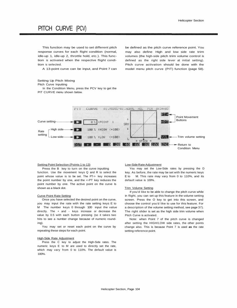
In the Condition Menu, press the PCV key to get thePIT CURVE menu shown below.
Curve setting-
Ratesetting
High side-
Low side-
Point MovementButtons
Trim volume setting
Return toCondition Menu
Setting Point Selection (Points 1 to 13)Press the B key to turn on the curve inputting
function. Use the movement keys Q and R to select thepoint whose value is to be set. The PT-> key increasesthe point number by one, and the <-PT key reduces thepoint number by one. The active point on the curve Isshown as a black dot.
Curve Point Rate SettingOnce you have selected the desired point on the curve,
you may input the rate with the rate setting keys E toM The number keys 0 through 100 input the valuedirectly. The + and - keys increase or decrease thevalue by 0.5 with each button pressing (so it takes twohits to see a number change because of numeric round-ing).
You may set or reset each point on the curve byrepeating these steps for each point.
High-Side Rate AdjustmentPress the C key to adjust the High-Side rates. The
numeric keys E to M are used to directly set the rate,which may vary from 0 to 110%. The default value is
100%.
Low-Side Rate AdjustmentYou may set the Low-Side rates by pressing the D
key. As before, the rate may be set with the numeric keysE to M. This rate may vary from 0 to 110%, and itsdefault value is 100%.
Trim Volume SettingIf you'd like to be able to change the pitch curve while
in flight, you can set up this feature in the volume settingscreen. Press the O key to get into this screen, andchoose the control you'd like to use for this feature. Fora description of the volume setting method, see page 37).The right slider is set as the high side trim volume whenPitch Curve is activated.
Note: when Point 7 of the pitch curve is changedafter setting the HIGH/LOW side rates, the other pointschange also. This is because Point 7 is used as the ratesetting reference point.
Helicopter Section, Page 104

Helicopter Section
HOVERING PITCH (PHV)
This function trims the pitch near the hovering
point. By setting a range, adjustment is possible
without changing the high and low points. This
Hovering pitch setting can be made for each flight
condition, but is commonly used for Normal flight
condition.
At initial definition, the left sliding lever con-
trols hovering pitch volume.
Activation of commandIn the Condition Menu, press the PHV key to get the
PIT HOVER menu shown below. Use the A key toactivate mode setting, then press the ACT or INHkeys ( F and G) to activate or inhibit the function.
Mode setting
Hovering Throttletrim volume setting
• Return toConditionscreen
Trim deflectionsetting
Range setting
Rate setting
Mode selection
Hovering Pitch Trim Deflection SettingPress the B key to allow input to this setting, and
input the rate with the numeric keys F to M . Thedeflection may be set from 0 to 100% (the initial value ofthis parameter is defined to be 100%).
Setting of RangeNow you will set the Range of travel over which
HIGH/LOW sides do not change. Press the Ckey and setthe rate with the numeric keys F to M. The Range maybe set from 0 to 100% (when activated, the initial value ofthis parameter is defined to be 100%).
Offset Rate SettingThe offset amount is entered by pressing the D key,
and input with the numeric keys E to M. This may beinput from -100 to +100%, and the initial value isprogrammed to 0%.
Hovering Pitch Trim Selection and Operation DirectionSetting
Call up the volume setting screen by pressing theVOL O key. Set the volume control as desired (theleft-side slider is set as the pitch trim volume controlinitially). For a description of the volume setting method,see page 37).
PrecautionsWhen the range is set to 100%. the rate changes be-
tween points 1 and 13. When the range is set to 0%, therate changes only between points 6 and 8. When you usethis function, set up the numbers so that when the rangeis small, the trim deflection is also small, and make surethat the preceding and following points are not exceededwhen the range is moved to its maximum position.
Helicopter Section, Page 105

Helicopter Section
PITCH TRIM (PTM)
This function enables you to move the pitch
trim (offset the trim) without changing the pitch
curve. The amount of pitch trim can be adjusted,
and may change for each condition.
At initial setting, the left side knob VR(A) is
defined as the pitch trim volume control. How-
ever, the knob is not activated at initial setting.
Activation of commandIn the Condition Menu, press the PTM key to get the
PITCH TRIM menu shown below. Use the A keyto activate mode setting, then press the ACT or INHkeys (F and G) to activate or inhibit the function.
Servo
Pitch TrimRate
StickPosition
Mode setting
Pitch Trim RateAdjustment
Pitch trimVolume setting
Return toCondition screen
Mode selection
Rate settingPress the B to input the rate to be set with the
numeric keys F to M . The rate setting may range from0 to 100%. and is initially programmed as 30%.
Volume selectionEnter the volume setting screen by pressing theO
key. For a description of the volume setting method, seepage 37. The left side knob is set as the volume control atinitial setting, but is not activated. Be sure that you aresetting for the desired condition by first turning on thecondition switch and verifying the condition name.
Helicopter Section, Page 106

Helicopter Section
THROTTLE CURVE (TCV)
This function programs throttle curves to per-
form hovering, loops, rolls, and other aerobatics in
the different flight modes. The throttle curve sets
the servo response over the full stroke of the
throttle stick by a 13-point curve. The low side
rate can be input (point 7 is the reference). The
servo delay at idle-up and other flight condition
switching can be programmed.
Setting Up The Throttle Curve FunctionThrottle Curve Inputting
In the Condition Menu, press the •TCV key to get theTHR CURVE menu shown in the upper portion of thefigure below.
Curve setting
Low SideRate Setting
Delay AmountSetting
Point Movement
To Next Screen
Return ToCondition Menu
To PrecedingScreen
Setting Point Selection (Points 1 to 13)Press the B key to turn on the curve inputting
function. Use the movement keys Q and R to select thepoint whose value is to be set. The PT-> key increasesthe point number by one, and the <-PT key reduces thepoint number by one. The active point on the curve isshown as a black dot.
Once you have selected the desired point on the curve,you may input the rate with the rate setting keys E toM . The number keys 0 through 100 input the valuedirectly. The + and - keys increase or decrease thevalue by 0.5 with each button pressing (so it takes twohits to see a number change because of numeric round-ing).
You may set or reset each point on the curve byrepeating these steps for each point.
Low-Side Rate AdjustmentPress the D key and you may input the rate with the
numeric keys E to M. You may set anywhere in therange from 0 to 110% (initially the rate is set to 100%).
Delay settingShift to the next screen (the lower one in the figure)
by pressing the NXT (P) key. Enter the delay with therate setting keys E to M. The delay may be set from 0to 100%, and is initially set to 0%.
Use the END (N) key to leave this menu.
Helicopter Section, Page 107

Helicopter Section
HOVERING THROTTLE (THV)
This function is used to trim the throttle
around is hovering position. By setting a range,
adjustment is possible without changing the high
and low points. This Hovering throttle setting can
be changed between the flight conditions, and
ACT/INH may be set separately for each.
At initial definition, the right knob VR(B)
controls hovering throttle trim.
Servo Servo
Stick Stick
Activation of commandIn the Condition Menu, press the THV key to get the
THR HOVER menu shown below. Use the A keyto activate mode setting, then press the ACT or INHkeys F and G) to activate or inhibit the function.
Mode setting
Trim DeflectionWidth Setting
Range setting
Rate setting Hovering Pitchtrim volume setting
Return toCondition Menu
Mode selection Actual Value, Including Volume Adjustment
Hovering Throttle Trim Deflection SettingPress the B key to allow input to this setting, and
input the rate with the numeric keys F to M. Thedeflection may be set from 0 to 100% (when activated,the initial value if this parameter is defined at 100%).
Setting of RangeNow you will set the Range of travel over which
HIGH/LOW sides do not change. Press the C key and setthe rate with the numeric keys F to M. The range maybe set from 0 to 100% (when activated, the initial value ifthis parameter is defined at 100%).
Offset Rate SettingThe offset amount is entered by pressing the D key,
and input with the numeric keys E to M . This may beinput from -100 to +100%, and the initial value isprogrammed to 0%.
Hovering Throttle Trim Selection and Operation DirectionSetting
Call up the volume setting screen by pressing theVOL O key. Set the volume control as desired (theright-side knob VR(B) is set as the pitch trim volumecontrol initially). For a description of the volume settingmethod, see page 37).
Helicopter Section, Page 108
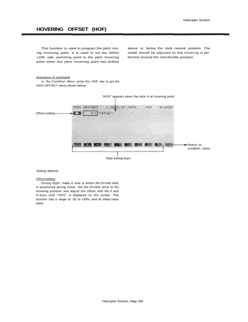
Helicopter Section
HOVERING OFFSET (HOF)
This function is used to program the pitch mix-
ing hovering point. It is used to set the HIGH/
LOW side switching point to the pitch hovering
point when the pitch hovering point has drifted
above or below the stick neutral position. The
model should be adjusted so that hovering is per-
formed around the mid-throttle position.
Activation of commandIn the Condition Menu, press the HOF key to get the
HOV OFFSET menu shown below.
"HOV" appears when the stick is at hovering point
Offset setting
Return tocondition menu
Rate setting keys
Setting Method
Offset settingDuring flight, make a note of where the throttle stick
is positioned during hover. Set the throttle stick to thehovering position and adjust the offset with the F andG keys until "HOV" is displayed on the screen. Thisfunction has a range of -30 to +30%, and its initial valueis0%.
Helicopter Section, Page 109

Helicopter Section
THROTTLE HOLD (HLD)
This function moves the throttle servo to idle
during auto rotation. Either a Manual mode or an
Auto mode can be selected. In the manual mode,
the throttle servo is held by turning on the throttle
hold switch. In the auto mode, the throttle servo is
held when the throttle stick is moved past the set
position on the low throttle side after the throttle
hold switch is turned on.
A delay up to the servo hold position can be
set. Throttle trim can be turned on and off during
throttle hold, but it is usually turned on.
Activation of commandIn the Condition Menu, press the HLD key to get the
THR HOLD menu shown below.
Mode settingThrottle TrimON/OFF
Hold PositionSetting
Delay setting
ON/OFFSwitch Setting
Trim VolumeSetting
Return tocondition menu
Mode selection
Select Operation ModeUse the A key to activate mode setting. Now
you must decide on Manual or Auto operation.Select the manual mode by pressing the MAN (G)
key. Select the auto mode by pressing the AUT ( H)key. You may deactivate the function by pressing the F
(INH) key.
Throttle hold ON/OFF switch settingCall the switch setting screen by pressing the SWT
(P ) key. At initial setting. SW (G) is defined as the con-trol switch. You may choose another switch with thismenu. For a description of the switch setting method, seepage 37.
Stick Position Setting (Auto Mode Only)For the Auto mode, you need to input the position at
which the function will take effect. Press the B key, thenmove the throttle stick to the desired position, and pressthe SET (F) key to memorize the position. If thethrottle stick is near half-throttle position for hovering,this should be around 20% throttle position.
Servo Hold Position SettingPress the C key and set the Idling position with the
rate setting keys F to M . This setting may vary from 0to 100%, and is initially set to 15% by the system. At theset position, the carburetor should be fully closed.
Delay settingPress the D key and set the delay with the rate setting
keys F to M . The setting range is 0 to 100%, and theinitial value loaded is 0%.
Throttle trim ON/OFF at throttle holdPress the R key to enter the throttle trim activation
menu. The function may be activated by pressing theACT ( F) key, and deactivated by pressing the INH(G) key.
Servo Hold Position Trim Volume Selection and Operat-ing Direction Setting
You may set a control to adjust the trim volumeduring flight. For a description of the volume settingmethod, see page 37. This volume is not loaded at initialsetting, but may be adjusted ±10% by the volume control.
Helicopter Section, Page 110

Helicopter Section
SWASHPLATE TYPE (SWP)
The SWP function has two built-in functions:
Swash--Throttle mixing, and Swash rotation.
These functions can be set for each flight condi-
tion. Swash->Throttle mixing is used to correct the
tendency of the model to change altitude when
the rotor is tilted by aileron, elevator, and other
controls. The Swash Rotation function is used
when the swash plate connections are shifted a
fixed angle from the reference position.
Using the Swashplate Menu
In the Condition Menu. press the SWP key to get theSWASH PAR menu shown below.
Mode setting
Mixing ratesetting
Mode setting
Angle setting
Swashthrottlemixing
Swashrotation
Return tocondition menu
Mode selection
Activation of Swash-Throttle Mixing commandUse the R key to activate mode setting, then press the
ACT or INH keys ( F and G ) to activate or inhibitthe aileron differential function.
Swash-Throttle Mixing Rate SettingPress the Q key and enter the desired mixing rate
with the rate setting numeric keys F to M. Mixing maybe set from 0 to 100%; the system enters an initial valueof 50%.
Swash Rotation SettingPress the P to turn the swash rotation setting menu
on. You may activate the offset mixing by pressing theACT (F) key, and deactivate by pressing the INH
(G) key.
Swash Rotation Angle InputtingPress the O key and set the angle with the angle
setting numeric keys E to M . This value may be setanywhere between -30° to +30°, and its initial value isset to 0°.
Helicopter Section, Page 111
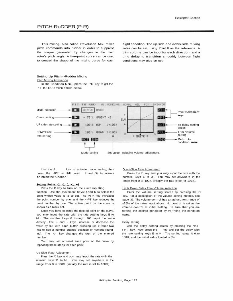
Helicopter Section
PiTCH-RuDDER (P-R)
This mixing, also called Revolution Mix. mixes
pitch commands into rudder in order to suppress
the torque generated by changes in the main
rotor's pitch angle. A five-point curve can be used
to control the shape of the mixing curve for each
flight condition. The up-side and down-side mixing
rates can be set, using Point 0 as the reference. A
trim volume can be input for each direction, and a
time delay to transition smoothly between flight
conditions may also be set.
Setting Up Pitch->Rudder MixingPitch Mixing Activation
In the Condition Menu, press the P-R key to get thePIT TO RUD menu shown below.
Mode selection
Curve setting
UP side rate setting
DOWN siderate setting
Point movementkeys
To delay settingscreen
Trim volumesetting
Return tocondition menu
Mode setting Set value, including volume adjustment.
Use the A key to activate mode setting, thenpress the ACT or INH keys F and G) to activateor inhibit the function.
Setting Points -2, -1, 0, +1, +2Press the B key to turn on the curve inputting
function. Use the movement keys Q and R to select thepoint whose value is to be set. The PT-> key increasesthe point number by one, and the <-PT key reduces thepoint number by one. The active point on the curve isshown as a black dot.
Once you have selected the desired point on the curve,you may input the rate with the rate setting keys E toM . The number keys 0 through 100 input the valuedirectly. The + and - keys increase or decrease thevalue by 0.5 with each button pressing (so it takes twohits to see a number change because of numeric round-ing). The +/- key changes the sign of the enterednumber.
You may set or reset each point on the curve byrepeating these steps for each point.
Up-Side Rate AdjustmentPress the C key and you may input the rate with the
numeric keys E to M . You may set anywhere in therange from 0 to 100% (initially the rate is set to 100%).
Down-Side Rate AdjustmentPress the D key and you may input the rate with the
numeric keys E to M . You may set anywhere in therange from 0 to 100% (initially the rate is set to 100%).
Up & Down Sides Trim Volume selectionEnter the volume setting screen by pressing the O
key. For a description of the volume setting method, seepage 37. The volume control has an adjustment range of±25% of the rates input above. No control is set as thevolume control at initial setting. Be sure that you aresetting the desired condition by verifying the conditionname.
Delay settingCall the delay setting screen by pressing the NXT
( P ) key. Now press the key and set the delay withthe rate setting keys E to M . The setting range is 0 to100%, and the initial value loaded is 0%.
Helicopter Section, Page 112
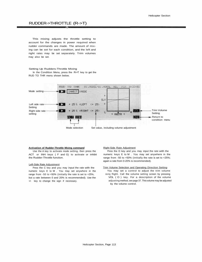
Helicopter Section
RUDDER->THROTTLE (R->T)
This mixing adjusts the throttle setting to
account for the changes in power required when
rudder commands are made. The amount of mix-
ing can be set for each condition, and the left and
right rates may be set separately. Trim volumes
may also be set.
Setting Up Rudders-Throttle Mixing
In the Condition Menu, press the R->T key to get theRUD TO THR menu shown below.
Mode setting
Left side rateSetting
Right side ratesetting
Trim VolumeSetting
Return tocondition menu
Mode selection Set value, including volume adjustment
Activation of Rudder-Throttle Mixing commandUse the A key to activate mode setting, then press the
ACT or INH keys ( F and G) to activate or inhibitthe Rudder-Throttle function.
Left-Side Rate AdjustmentPress the C key and you may input the rate with the
numeric keys E to M . You may set anywhere in therange from -50 to +50% (initially the rate is set to +25%,but a rate between 0 and 20% is recommended). Use the+/- key to change the sign if necessary.
Right-Side Rate AdjustmentPress the D key and you may input the rate with the
numeric keys E to M . You may set anywhere in therange from -50 to +50% (initially the rate is set to +25%;again a rate from 0-20% is recommended).
Trim Volume Selection and Operating Direction SettingYou may set a control to adjust the trim volume
during flight. Call the volume setting screen by pressingVOL ( O ) key. For a description of the volumeadjusting method, see page 37. This volume may be adjusted
by the volume control.
Helicopter Section, Page 113

Helicopter Section
GYRO SENSITIVITY (GYR)
This function switches the gyro sensitivity. Themode depends on the gyro used. Usually, sensiti-vity 1 or 2 is switched in the normal mode.
The Normal mode is used with gyros havingtwo-step switching. The sensitivity is pre-adjustedat two values and is selected by means of thisfunction.
The Linear mode is used with gyros whosesensitivity can be switched linearly. The sensitivitycan be lowered according to the rudder travel bymeans of this function.
An EXP mixing curve may also be input. Thesensitivity remains constant (maximum sensitivity)up to the point at which gyro sensitivity is sup-pressed according to rudder operation. However,the maximum and minimum sensitivities are set atthe gyro.
Linear Mode
Position 0%
Gyro Sensitivity
Position 100%
Gyro Sensitivity
100% 100%
Using the Gyro Sensitivity MenuIn the Condition Menu. press the GYR key to get the
GYRO SENSE menu shown below.
Mode setting
Sensitivity No.Selection
Return tocondition menu
Mode setting
Rudder stickposition settingEXP rate setting
Mode selection
Helicopter Section, Page 114

Helicopter Section
Select the Gyro ModePress the A key to enter the mode selection menu.
Select the normal mode by pressing the NOR ( F ) key.Select the linear mode by pressing the LIN ( G ) key.Deactivate the function by pressing the INH ( H ) key.
Normal mode
Select the sensitivity number by
pressing the F ( 1 ) or G ( 2 )key.
Linear mode
Set Rudder Stick PositionPress the C key and set the rudder stick position with the numeric keys
F to M. You may input from 0 to 100% (initially 50% is entered). Thenumeric keys input the number; ( + ) and ( - ) change the inputted value by+/- 1, and the +/- key changes the sign.
Set EX P ratePress the D key and set the curve rate with the numeric keys F to M.
The numeric keys work the same as given in the previous paragraph.
Press the END (N) key to exit this menu.
Helicopter Section, Page 115

Helicopter Section
ACCELERATION (ACC)
This mixing function is used to cancel the re-
action torque generated by sudden throttle
changes. The amount of mixing and the rudder
servo return delay can both be programmed.
Using the Acceleration FunctionIn the Condition Menu, press the ACC key to get the
ACCELER menu shown below.
Mode setting
Mixing rate setting
Delay setting
• Return toCondition Menu
Mode selection
Activation of Acceleration Command Delay settingUse the A key to activate mode setting, then press the Call the delay setting screen by pressing the 0 key.
ACT or INH keys (F and G) to activate or inhibit Now set the delay with the rate setting keys F to M.the Acceleration function. The setting range is 0 to 100%. and the initial value loaded
is 50%.Mixing rate setting
To input the mixing rate, press the C key and set the Exitingmixing rate with the rate setting keys F to M. The mix- To exit the Acceleration Mix function, use the ENDing rate is initially set to a value of 50%, but may be set N key.from 0 to 100% using the numeric keys.
Helicopter Section, Page 116

Helicopter Section
INVERTED PITCH (INV)
This function sets the inverted pitch high-
side and low-side rates during inverted flight. All
linkages should be set up for inverted flight. In-
verted flight function activation and cross position
setting are performed with the Inverted Pitch
(INV) function in the model menu (page 57).
Setting Up The Inverted Pitch FunctionIn the Condition Menu, press the INH key to get the
INV PITCH menu shown below.
High sidepitch setting
Low side pitchsetting
Return toconditionmenu
Numeric keys
Inverted Flight High Pitch Rate SettingPress the C key and you may input the rate with the
numeric keys F to M . You may set anywhere in therange from 0 to 110% (initially the rate is set to 100%).
Inverted Flight Low Pitch Rate AdjustmentPress the D key and you may input the rate with the
numeric keys F to M. You may set anywhere in therange from 0 to 100% (initially the rate is set to 100%).
ExitingTo exit the Acceleration Mix function, use the END
N key.
Helicopter Section, Page 117

Sailplane Section
SAILPLANE SECTION
This section contains information on the commands that apply to
sailplanes only. Each of these functions can be set independently for
different flight conditions. The sailplane model types are grouped
into 2-S type, 4-S type, and 5-S type by number of servos in the
wing. The Condition menus for these three sailplane types are shown
on the next page.
In this manual, speed flaps are controls that can move together
(as flaps) or differentially (as ailerons), and are commonly found on
most high-performance models. Brake flaps move together only, and
are used for landing. Brake flaps are sometimes found on scale
models. Butterfly is a high drag configuration used for landings,
referred to as "Crow" elsewhere.
If you plan to use the PCM 1024Z system primarily for sailplanes
and would like to have a three position switch on the left-hand side,
we recommend you purchase a Mode I airplane radio (and convert
to Mode II) or a Mode II helicopter radio.
For conditions that apply to all models (ATV, AFR, D/R, PMX,
STM, TOF, CNA, and TRM functions), refer to the Common Con-
ditions section. For instructions on Helicopters and Airplanes, refer
to the sections pertaining to those aircraft.
Sailplane Section Table of Contents___________________________Sailplane Transmitter Controls and Functions. . . . . . . . . . . . . . . . . 120Sailplane Receiver and Servo Connections. . . . . . . . . . . . . . . . . . . 121Sailplane Setup Example. . . . . . . . . . . . . . . . . . . . . . . . . . . . . 122
Control Setup Definitions_________________________________ADF . . . . .Aileron Differential. .. . . . .Sets different aileron up . . . 125
(2-S/4-S/5-S) & down throwsA-R . . . . .Aileron-> Rudder. . . . . . . .Mixing for low-drag, . . . . . 126
(2-S/4-S/5-S) coordinated turnsASF. . . . . .Aileron-» Speed flap . . . . . .Increased roll authority for . 127
(4-S/5-S) 4-S & 5-SVTL . . . . .V-Tail. . . . . . . . . . . . . . .Mixes rudder & elevator . . . 128
for V tailABE . . . . .Air Brake-> Elevator. . . . . .Trims pitch change due. . . . 129
(2-S/4-S/5-S) to airbrakesEBF. . . . . .Elevator-<• Brake Flap . . . . .High lift for better . . . . . . 130
(5-S) turning capability, 5-SESP. . . . . . E I evator-- Speed Flap . . . . .High lift for better . . . . . . 131
(4-S) turning capability, 4-SBKF . . . . .Brake Flap (5-S) . . . . . . . . .Special flap mixing . . . . . . 132
functions, 5-SSPF . . . . . .Speed Flap (4-S) . . . . . . . .Special flap mixing . . . . . . 135
functions, 4-SSFT. . . . . .Speed Flap Trim . . . . . . . .Use to change wing . . . . . . 139
(4-S/5-S) camber on 4-S & 5-SBFY . . . . .Butterfly (4-S/5-S) . . . . . . .High drag for predictable. . . 140
landingsBYE . . . . .Butterfly-> Elevator ..... .Compensates for . . . . . . . 142
(4-S/5-S) butterfly trim changeETM . . . . .Elevator Trim (2-S/5-S) . . . .Elevator Presets for flight . . 143
conditionsTM1&2. . . .Trim Mix 1 & 2 (4-S) . . . . . .Two presets for . . . . . . . . 145
different flight conditionsP-»E . . . . .Flap-» Elevator (2-S). . . . . .Corrects trim change . . . . . 147
due to flap motionE-»F . . . . .Elevator-> Flap (2-S). . . . . .High lift for better . . . . . . 148
turning, 2-SPPN. . . . . .Flaperon (2-S). . . . . . . . . .Combined flap & aileron. . . 149
functions, 2-S
Sailplane Section, Page 118

Sailplane Section
SAILPLANE CONDITION MENUS
Five Servo Type (5-S)
LineSelectionKeys
To Home Screen
To System Menu
To Model Menu
To condition hold menu
Function Selection Keys
Four Servo Type (4-S)
Two Servo Type (2-S)
To get to these settings, press the MDL key from anymenu in an Sailplane setup. To select one, first select theline containing the desired function with the B , C , orD keys. Then use the F to L keys to select the functionto be entered.
Sailplane Section, Page 119

Sailplane Section
SAILPLANE TRANSMITTER CONTROLS AND FUNCTIONS
Functions and locations given in this drawing arethe factory default positions. Each setting can beeasily changed as the owner desires. The FunctionChange menu [FNC] may be used for this pur-pose.
Sail plane Section, Page 120

Sailplane Section
SAILPLANE RECEIVER AMD SERVO CONNECTIONS
The order for connecting the servos depends onthe selected number of wing servos (two, four, orfive wing servos). When dual aileron or flap servos
are not required, the receiver output channels areavailable for other uses. V-tail connections = *The receiver output order is shown below:
Sailplane Section, Page 121
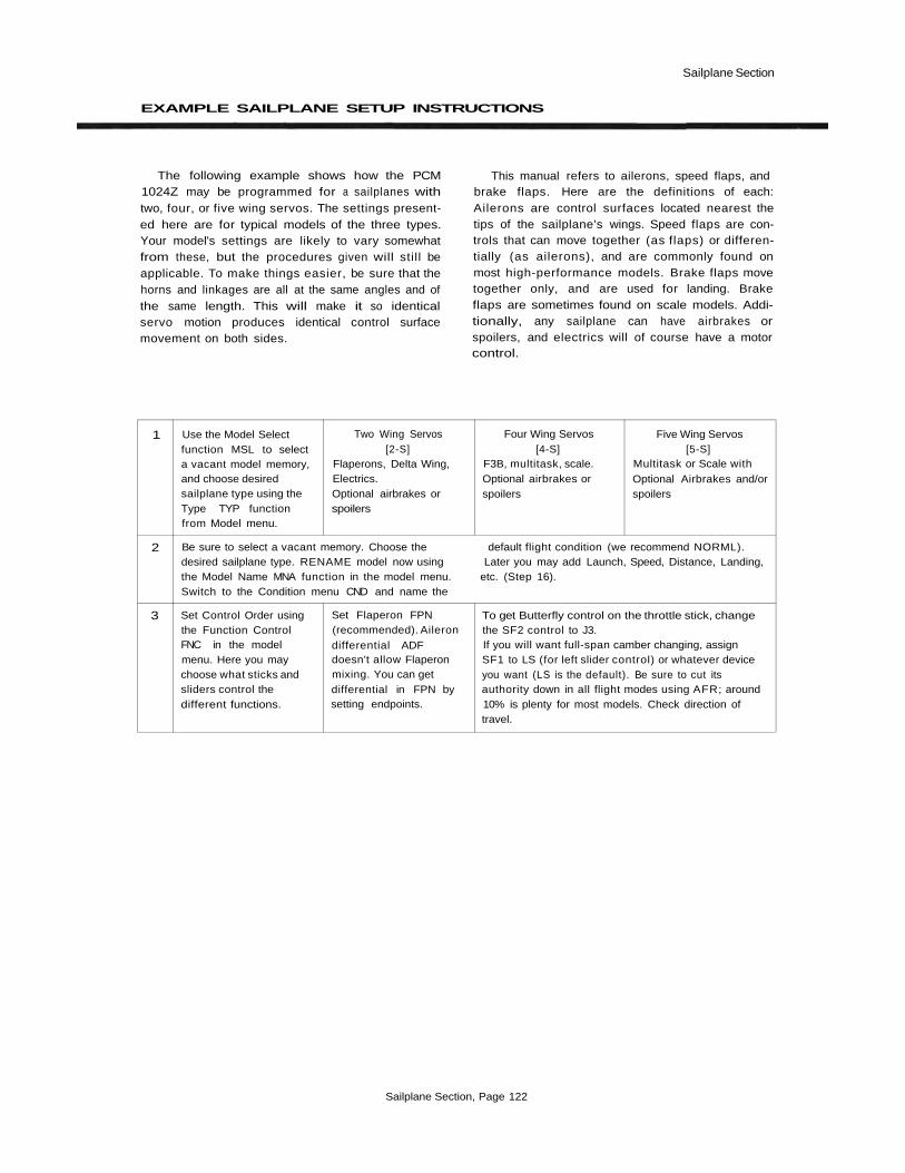
Sailplane Section
EXAMPLE SAILPLANE SETUP INSTRUCTIONS
The following example shows how the PCM1024Z may be programmed for a sailplanes withtwo, four, or five wing servos. The settings present-ed here are for typical models of the three types.Your model's settings are likely to vary somewhatfrom these, but the procedures given will still beapplicable. To make things easier, be sure that thehorns and linkages are all at the same angles and ofthe same length. This will make it so identicalservo motion produces identical control surfacemovement on both sides.
This manual refers to ailerons, speed flaps, andbrake flaps. Here are the definitions of each:Ailerons are control surfaces located nearest thetips of the sailplane's wings. Speed flaps are con-trols that can move together (as flaps) or differen-tially (as ailerons), and are commonly found onmost high-performance models. Brake flaps movetogether only, and are used for landing. Brakeflaps are sometimes found on scale models. Addi-tionally, any sailplane can have airbrakes orspoilers, and electrics will of course have a motorcontrol.
1
2
3
Use the Model Selectfunction MSL to selecta vacant model memory,and choose desiredsailplane type using theType TYP functionfrom Model menu.
Be sure to select a vacant memory. Choose the default flight condition (we recommend NORML).desired sailplane type. RENAME model now using Later you may add Launch, Speed, Distance, Landing,the Model Name MNA function in the model menu. etc. (Step 16).Switch to the Condition menu CND and name the
Set Control Order usingthe Function ControlFNC in the modelmenu. Here you maychoose what sticks andsliders control thedifferent functions.
Two Wing Servos[2-S]
Flaperons, Delta Wing,Electrics.Optional airbrakes orspoilers
Set Flaperon FPN(recommended). Ailerondifferential ADFdoesn't allow Flaperonmixing. You can getdifferential in FPN bysetting endpoints.
Four Wing Servos[4-S]
F3B, multitask, scale.Optional airbrakes orspoilers
To get Butterfly control on the throttle stick, changethe SF2 control to J3.If you will want full-span camber changing, assignSF1 to LS (for left slider control) or whatever deviceyou want (LS is the default). Be sure to cut itsauthority down in all flight modes using AFR; around10% is plenty for most models. Check direction oftravel.
Five Wing Servos[5-S]
Multitask or Scale withOptional Airbrakes and/orspoilers
Sailplane Section, Page 122

Sailplane Section
4
5
6
7
8
9
10
11
12
13
14
15
Instruction
Set V-Tail (if needed).Choose motor control channel from spares (if used).
Plug Servos into CorrectChannel Numbers
* = V-Tail outputsUnnumbered receiver
outputs are spares.
Use Reversing Function REV in the Model menu to necesary to correct throws.set proper throw directions. Reverse channels as
If you will use multiple flight modes, choose and set Typically down is used for launch presets, and up isswitch for default flight mode. We recommend using used for speed presets. These conditions are set inthe center position of the 3-position switch E. step 16.
Set Aileron Differential ADF . More up (reflex) Approximately 2:1 up:down ratio is a good startingthan down helps make coordinated low-drag turns, point. At high speeds less or none is needed.
Set Aileron->Rudder coupling A->R if desired. Only Little or no coupling is needed for high speeds. Usea small percentage is needed, around 10—15%. This the switch SWT command to define the ON positionreduces drag of fuselage yawing to make low-drag of SW-E.turns. Be sure that rudder moves in correct direction.
Glide path controlactivation. Set these upfor steeper descent andmore precise landings.
Couple Flaps to elevatorfor tighter pylon turns("Nobler" mixing).Most models don't needmuch (1/16"-1/8"atwing trailing edge)
Faster roll rate mixing(have the speed flapsmove as ailerons)
Trim inboard flaps
Switchable elevator trim(make small changes)
Set Throw Volumes ATV to prevent binding. Check each servo at each extreme of motion in all flight modes.
2-S
Ch 1 = Ail 1Ch 2 = Elevator*Ch 3 = AirbrakeCh 4 = Rudder*Ch 5= Ail 2 (in FLP
mode)Ch 7= Ail 2 (in DIF
mode)
Set flap travel (usuallyas much as you can getand still have rollcontrol). Spoilers willhelp steepen approach.
Set Elev->Flap E->F
—
Set Elev trim offsetETM for different flightconditions.
4-S
Ch 1 = Ail 1Ch 2= Elevator*Ch 3 = AirbrakeCh 4= Rudder*Ch 5= Flap 1Ch6= Flap 2Ch 7= Ail 2
Set Butterfly BFY .Be sure Aileron go upequal amounts, speedflaps go down equalamounts. Lots of flap(90°) is better.
Set Elev->Speed FlapESF mixing.
AddSpeed Flap->AileronMixing SPF at 100%for uniform wing camberchange.
Aileron->Speed Flapmixing ASF.Suggest 50% forthermalling, 80-100% forspeed.
Set speed flap trim SFT— . This might be used forlanding or cruise preset posit ons.
~~
5-S
Ch 1 = Ail 1Ch 2 = Elevator*Ch 3= AirbrakeCh 4 = Rudder*Ch5=F lap1Ch 6= Flap 2Ch 7 = Ail 2Ch 8 = Brake flap
Set Butterfly BFY .Be sure Ailerons go upequal amounts. BrakeFlaps may be coupled tospeed flaps BKF tormore drag.
Set Elev->Brake FlapEBF mixing.Brake Flaps may becoupled to speed flapsusing BKF for more liftcapability if desired.
Aileron->Speed Flapmixing ASF .
Suggest 50% forthermalling, 80-100% forspeed.
Set Elev trim offsetETM for different flightconditions.
Sailplane Section, Page 123

Sailplane Section
16
Instruction 2-S 4-S 5-S
After a few flights to trim the model, you may set you may go through the Condition menu items todifferent flight modes. You may trim for launch flap/ get the desired settings in the new mode. Read theaileron droop, speed camber reflex, or other desired condition name after the model name to be sure youflight modes. You can have different subtrims, rudder are changing the condition you want.coupling, differential, aileron/speed flap mixing. In Now, you may go through the Condition menu itemsfact you may change EVERY parameter between (i.e. ADF, A->R, etc.) to get the desired settings inflight modes, the new mode. Read the condition name after theUse the Condition Select CSL button in the Model model name to be sure you are changing the conditionMenu. This function allocates the necessary number you want.of flight conditions to the model memory. Note the As an example, for NORML we use approximatelycondition number next to the D (default) in the 50% ASF mixing, 50% differential, and 10% A->Rdisplay. This is the set of conditions that will be coupling. In the speed mode, we use 100% ASF forcopied into a new condition and modified. Also note better roll rate, 0% differential, and turn A->R downthe number after the next display. You will copy to to zero because adverse yaw is very small at highthis condition, speeds. Subtrims and Trim Mixes 1 &2 may be usedNow use the Copy Condition CPC from the System to offset controls for different conditions, like flapmenu to copy the contents of the default condition droop for launch.into another. Choose the default flight condition You can modify all of the settings and adjust each asnumber, press the SET button, then choose the you like. You can add a time delay on many of thesecond condition number in the lower box "TO menus: look for a DELAY setting. You can also haveCONDITION." Give the command to copy. the mixing ratio vary with the motion of anotherThe switch that calls the flight conditions should be slider or knob: look for the VOL key on the Elselected. Return to the Condition Select CSL button in some menus.function, press the desired flight condition number, (Note: In the 4-servo model, if you don't mind havingand use the SWT button to choose the desired the same differential, mixing, etc. settings for allswitch location, modes, you can easily set Trim Mix 1 & Trim Mix 2Once you have selected a condition, use the CNA TM1 , TM2 to droop flaps and ailerons, and trim(Condition Name) button to label the new condition elevator for both launching and speed. Then you do(you may have to flip the chosen switch to the not have to use any other flight condition settings.)correct position to get the desired condition). Now,
After test flying, change compensation for glide path commands reacting & changing trim:
17
18
19
20
Instruction
Set elevator presets for launch and speed, or other flight conditions as desired. Make small changes.
Reduce rudder coupling A->R if fuselage points inward to center of turns, and increase if the fuse pointsoutwards during turns. Turn it off for speed.
Glidepath trimcorrection (Caution:make only small changesin elevator mixing)
Airbrake or spoiler trimcorrection
2-S
For flap actuation trimchange: SetFlap->EIev F->E
Use Airbrake->Elevator ABE mixing to correct trim change due to airbrake/spoiler. Make small changes as trim is very sensitive to this.
4-S
For Butterfly trimchange: Set Butterfly-Elev BYE
5-S
Set Butterfly-ElevBYE . BrakeFlap->Elev BKF
Sailplane Section, Page 124

Sailplane Section
AlLERON DIFFERENTIAL (ADF)
This applies to all three sailplane types, 5-S,
4-S, and 2-S. The aileron differential function is
used to provide more deflection for the up aileron
than for the down aileron. Depending on the
model design, anywhere from 5 to 30% more up
deflection is used. The up and down travel of each
servo may be set separately. If desired, the amount
of down aileron deflection may be trimmed in
flight with a knob or trimmer.
When this function is defined, the required two
servos plug into receiver output channels CH1
(aileron 1) and CH7 (aileron 2).
Setting Up Aileron DifferentialActivation of command
In the Condition Menu, press the ADF key to get theAIL DIFF menu shown below. Use the A keyto activate mode setting, then press the ACT or INH
keys (F and G) activate or inhibit the aileron dif-ferential function.
Mode setting
Aileron 1 Left TravelRate Setting
Aileron 2 Left TravelRate Setting
Aileron 1 RightTravel Rate Setting
Aileron 2 RightTravel Rate Setting
Trim Volume Setting
Return To ConditionMenu
Mode Selection Keys
Aileron 1 Travel SettingYou now set the amount of servo throw for Aileron 1.
Press the B key to activate travel setting for the Leftdirection and set the throw with the numeric keys. Thenumber keys 0 through 100 input the value directly.The + and - keys increase or decrease the value by 1.The +/- key may be used to reverse the throw direc-tion.
If you are not sure what you are changing, hold thestick to one side and press different keys — if there is noeffect, move the aileron stick to the other side and con-tinue. Your setting may vary from —120 to +120%, theinitial value is +100%.
Now set the travel for the Right throw on Aileron 1.Press the Q key to activate travel setting for the Rightdirection and set the throw with the numeric keys asbefore.
Aileron 2 Travel SettingThe setting process given above is repeated for Aileron
2. Press the C key to activate travel setting for the Leftdirection and set the throw with the numeric keys.
Finally, set the travel for the Right throw on Aileron2. Press the P key to activate travel setting for the Rightdirection and set the throw with the numeric keys asbefore.
Trim volume settingYou may set up the Aileron Differential function so
that its effect may be changed in flight by moving a trimcontrol. The trim control adjusts the volume within ±25%of the set differential rate. This option is not activated atinitial setup.
Call the volume setting screen by pressing the VOLO key, and select the desired control using the screenmenus (for a description of the volume setting method,see page 37).
Use the END (N ) key to leave this menu.
Sailplane Section, Page 125

Sailplane Section
ALLERON-RUDDER MIXING (A-R)
This function is used to mix rudder operation
with aileron operation automatically, to make
realistic, coordinated turns. It is especially effec-
tive when turning and banking scale models or
large models that resemble full-sized aircraft. This
mixing keeps the fuselage aligned into the wind,
reducing drag, and helps to make what are called
"coordinated turns."
The function allows you to set up the left and
right mixing rates independently. Furthermore,
mixing can be turned on and off during flight by
setting a switch, or it may be set to stay on all the
time if the function is activated (ACT) without
setting an ON/OFF switch. Also, it is possible to
adjust the amount of rudder coupling in-flight, by
setting a volume control.
Setting Up Rudder CouplingActivation of command
In the Condition Menu, press the A->R key to getthe AIL TO RUD menu, as shown below. Use the
A ( D ) key to activate mode setting, then press theACT or INH keys ( F and G) to activate or inhibitrudder coupling.
Mode setting
Mixing —Leftside-ratesetting I—Right side
ON/OFF switchsetting
Trimming volumesetting
Return toCondition screen
Mode Selection Values in ( ) are the mixing rate, including the trim volume.
Setting the Mixing Ratio — Left and RightFirst set the amount of mixing for left aileron com-
mand. Press the C key to activate mixing ratio for theLeft direction and set the value with the numeric keysE to M . The number keys 0 through 100 input thevalue directly. The + and - keys increase or decreasethe value by 1. The +/- key may be used to reverse thethrow direction.
If you are not sure what you are changing, hold thestick to one side and press different keys — if there is noeffect, move the aileron stick to the other side and con-tinue. Your setting may vary from —100 to +100%, theinitial value is+50%.
Now set the amount of mixing for the Right aileroncommand. Press the D key to activate mixing ratio forthe Right direction and set the throw with the numerickeys as before.
On/Off Switch SettingOn initial setting, an activation switch for rudder
coupling is not set, meaning that once activated, it is onall the time. If you would like to set a switch to turn it onand off, call the Switch Setting screen by pressing theSWT P key. Then use the keys to choose the desiredswitch location and on direction. For more informationon the switch setting method, see page 37).
Trim Volume settingYou may set up the Rudder coupling function so that
its effect may be changed in flight by moving a trimcontrol. The trim control adjusts the volume within ±25%of the set mixing rate. This option is not activated atinitial setup.
Call the volume setting screen by pressing the VOLO key, and select the desired control using the screenmenus (see page 37 for a description of the volume settingmethod.
Use the END (N ) key to leave this menu.
Sailplane Section, Page 126

Sailplane Section
AILERON-SPEED FLAP COUPLING (ASF)
This function may be used to control mixing
from the ailerons to the speed flaps, making the
entire wing act as ailerons. When the aileron stick
is moved, the aileron and speed flap servos operate
simultaneously, which improves the model's roll
rate.
Setting Up Speed Flap CouplingActivation of command
In the Condition Menu, press the ASF key to get theAIL TO SPF menu, as shown below. Use the A ( D ) keyto activate mode setting, then press the ACT or INHkeys ( F and G ) to activate or inhibit speed flap coupl-ing.
The left and right deflection angles of the speed
flap servos can be adjusted. Speed Flap mixing can
be made to turn on and off during flight by setting
a switch. Initially, an ON/OFF switch is not de-
fined, so mixing remains on all the time.
Mode setting
Flap 1 Left TravelRate Setting
Flap 1 Right TravelRate Setting
Next Screen
To On/Off SwitchSetting Menu
Mode Selection Keys
Return ToCondition Menu
Flap 2 Left TravelRate Setting
Flap 2 Right TravelRate Setting
To Next Screen
Flap 1 Left Travel SettingFirst set the amount of mixing throw for Flap 1. Press
the C key to activate travel setting for the Left directionand set the throw with the numeric keys E to M . Thenumber keys 0 through 100 input the value directly.The + and - keys increase or decrease the value by 1.The +/- key may be used to reverse the throw direc-tion.
If you are not sure what you are changing, hold thestick to one side and press different keys — if there is noeffect, move the aileron stick to the other side and con-tinue. Your setting may vary from -100 to +100%, theinitial value is +50%.
Now set the travel for the Right throw on Flap 1.Press the D key to activate travel setting, and set thethrow with the numeric keys as before.
Flap 2 Left Travel SettingYou now set the amount of mixing throw for Flap 2.
Press the NXT Q key to get to the flap 2 menu, thenpress the C key to activate travel setting for the Leftdirection and set the throw with the numeric keys E toM as you did for Flap 1.
Now set the travel for the Right throw on Flap 2.Press the D key to activate travel setting, and set thethrow with the numeric keys as before.
On/Off Switch SettingOn initial setting, an activation switch for speed flap
mixing is not set, meaning that once activated, it is on allthe time. If you would like to set a switch to turn it onand off, call the Switch Setting screen by pressing theSWT P key. Then use the keys to choose the desiredswitch location and on direction. For more informationon the switch setting method, see page 37).
Sailplane Section, Page 127

Sailplane Section
V-TAIL (VTL)
This function automatically sets up the PCM
1024Z to control a V-tail sailplane with com-
bined elevator and rudder functions. It requires
two servos, one hooked up to receiver output CH2
(elevator 1/rudder 2) and the second plugged into
CH4 (elevator 2/rudder 1). The elevator and rud-
der deflections can be adjusted independently.
Setting Up V-Tail MixingActivation of command
In the Condition Menu, press the VTL key to get theV-TAIL Mixing menu shown below. Use the A keyto activate mode setting, then press the ACT or INHkeys ( F and G ) to activate or inhibit V-Tail Mixing.
Elevator 1deflection angle
Rudder 1deflection angle
Elevator 2deflection angle
Rudder 2deflection angle
Return tocondition screen
Mode setting
Mode selection
Setting the Elevator Rates - 1 and 2Begin by setting the rate for Elevator 1. Press the B
key to activate rate setting for Elevator 1 and set the ratewith the numeric keysE to M. The number keys 0through 100 input the value directly. The + and -keys increase or decrease the value by 1. The +/- keymay be used to reverse the throw direction.
If you are not sure what you are changing, hold thestick to one side and press different keys — if there is noeffect, move the elevator stick to the other side and con-tinue. Your setting may vary from —100 to +100%. theinitial value is set to +50%.
Now set the rate for Elevator 2. Press the Q key toactivate Elevator 2 rate setting and set the rate with thenumeric keys as before.
Setting the Rudder Rates - 1 and 2You now set the rate for Rudder 1. Press the C key
to activate rate setting for Rudder 1 and set the rate withthe numeric keys E to M as before.
If you are not sure what you are changing, hold therudder stick to one side and press different keys — if thereis no effect, move the rudder stick to the other side andcontinue. The initial value is +50%, but your setting mayvary from -100 to +100%.
Now set the rate for Rudder 2. Press the P key toactivate Rudder 2 rate setting and set the rate with thenumeric keys as before.
Checking Your WorkAfter you have set up the V-Tail rates, be sure that
they move the correct directions. For up elevator com-mand, both V-tails should move upward. For right ruddercommand, the trailing edge of both surfaces should moveto the right. If they do not, use the +/- to reverse thedirection as needed.
Use the END ( N ) key to leave this menu.
Sailplane Section, Page 128
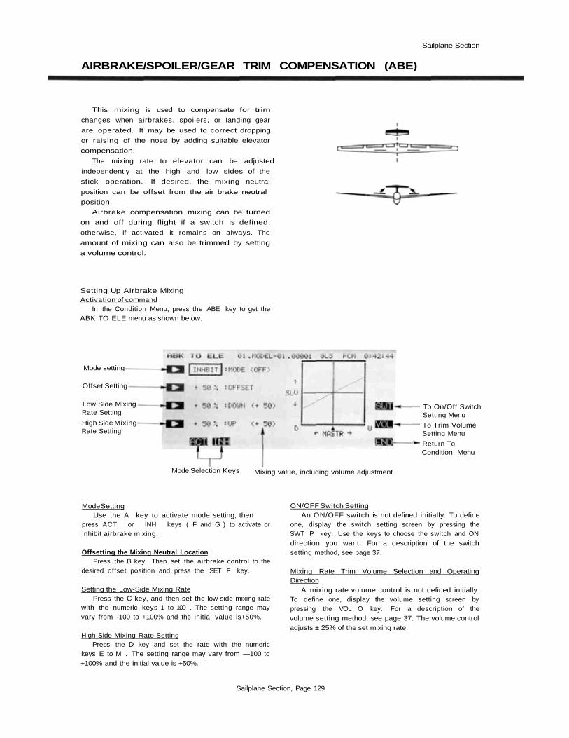
Sailplane Section
AIRBRAKE/SPOILER/GEAR TRIM COMPENSATION (ABE)
This mixing is used to compensate for trim
changes when airbrakes, spoilers, or landing gear
are operated. It may be used to correct dropping
or raising of the nose by adding suitable elevator
compensation.
The mixing rate to elevator can be adjusted
independently at the high and low sides of the
stick operation. If desired, the mixing neutral
position can be offset from the air brake neutral
position.
Airbrake compensation mixing can be turned
on and off during flight if a switch is defined,
otherwise, if activated it remains on always. The
amount of mixing can also be trimmed by setting
a volume control.
Setting Up Airbrake MixingActivation of command
In the Condition Menu, press the ABE key to get theABK TO ELE menu as shown below.
Mode setting
Offset Setting
Low Side MixingRate Setting
High Side MixingRate Setting
Mode Selection Keys
To On/Off SwitchSetting Menu
To Trim VolumeSetting Menu
Return ToCondition Menu
Mixing value, including volume adjustment
Mode SettingUse the A key to activate mode setting, then
press ACT or INH keys ( F and G ) to activate orinhibit airbrake mixing.
Offsetting the Mixing Neutral LocationPress the B key. Then set the airbrake control to the
desired offset position and press the SET F key.
Setting the Low-Side Mixing RatePress the C key, and then set the low-side mixing rate
with the numeric keys 1 to 100 . The setting range mayvary from -100 to +100% and the initial value is+50%.
High Side Mixing Rate SettingPress the D key and set the rate with the numeric
keys E to M . The setting range may vary from —100 to+100% and the initial value is +50%.
ON/OFF Switch SettingAn ON/OFF switch is not defined initially. To define
one, display the switch setting screen by pressing theSWT P key. Use the keys to choose the switch and ONdirection you want. For a description of the switchsetting method, see page 37.
Mixing Rate Trim Volume Selection and OperatingDirection
A mixing rate volume control is not defined initially.To define one, display the volume setting screen bypressing the VOL O key. For a description of thevolume setting method, see page 37. The volume controladjusts ± 25% of the set mixing rate.
Sailplane Section, Page 129

Sailplane Section
ELEVATOR-BRAKE FLAP MIXING (EBF)—5-S
This mixing is used to command the lowering
of the brake flaps when up elevator is given. This
coupling increases the lift that the wing can
deliver, resulting in tighter turns and better ma-
neuverability.
The mixing rates for elevator up and down
deflections can be set independently (for many
airfoils, down elevator to up flap mixing is not
recommended because of a large drag increase).
Mixing can be turned on and off during flight by
setting a switch, and the amount of mixing may
also be trimmed in flight by moving a volume
control.
Setting Up Elevator-Brake Flap CouplingActivation of command
In the Condition Menu, press the EBF key to get theELE TO BKF menu, as shown below.
Mode setting
Down Elev. MixingRate Setting
Up Elev. Mixing —Rate Setting
To On/Off SwitchSetting Menu
Trim VolumeSetting
Return ToCondition Menu
Mode Selection Keys Mixing value, including volume adjustment
Use the A key to activate mode setting, then pressthe ACT or INH keys ( F and G ) to activate orinhibit brake flap coupling.
Setting the Down Elevator Mixing RatePress the C key, and then set the down elevator
mixing rate with the numeric keys E to M . The settingrange may vary from -100 to +100% and the initial valueis +50%.
Up Elevator Mixing Rate SettingPress the D key and set the up elevator mixing rate
with the numeric keys E to M. The setting range mayvary from -100 to +100% and the initial value is +50%.
ON/OFF Switch SettingDisplay the switch setting screen by pressing the
SWT P key. Initially, SW (C) is set to be ON at 1position, but you may use the keys to choose the switchand ON direction you want. For a description of theswitch setting method, see page 37.
Mixing Rate Trim Volume Selection and OperatingDirection
A mixing rate volume control is not defined initially.To define one, display the volume setting screen bypressing the VOL O key. For a description of thevolume setting method, see page 37. The volume controladjusts ±25% of the set mixing rate.
Use the END ( N ) key to leave this menu.
Sailplane Section, Page 130

Sailplane Section
ELEVATOR-SPEED FLAP COUPLING (ESF)—4-S
This mixing is used to command the lowering
of the speed flaps when up elevator is given. This
coupling increases the lift that the wing can
deliver, resulting in tighter turns and better ma-
neuverability.
The mixing rates for elevator up and down
deflections can be set independently (for many
airfoils, down elevator to up flap mixing is not
recommended because of a large drag increase).
Mixing can be turned on and off during flight by
setting a switch, and the amount of mixing may
also be trimmed in flight by moving a volume
control.
Setting Up Elevator-Speed Flap CouplingActivation of command
In the Condition Menu, press the ESF key to get theELE TO SPF menu. as shown below.
Mode setting
Down Elev. MixingRate Setting
Up Elev. MixingRate Setting
To On/Off SwitchSetting Menu
Trim VolumeSetting
Return ToCondition Menu
Mode Selection Keys Mixing value, including volume adjustment
Use the A key to activate mode setting, then pressthe ACT or INH keys ( F and G ) to activate orinhibit speed flap coupling.
Setting the Down Elevator Mixing RatePress the C key, and then set the down elevator
mixing rate with the numeric keys E to M . The settingrange may vary from —100 to +100% and the initial valueis +50%.
Up Elevator Mixing Rate SettingPress the D key and set the up elevator mixing rate
with the numeric keys E to M . The setting range mayvary from -100 to +100% and the initial value is +50%.
Choosing An ON/OFF SwitchDisplay the switch setting screen by pressing the
SWT P key. Initially, SW (C) is set to be ON at 1position, but you may use the keys to choose the switchand ON direction you want. For a description of theswitch setting method, see page 37.
Mixing Rate Trim Volume Selection and OperatingDirection
A mixing rate volume control is not defined initially.To define one, display the volume setting screen bypressing the VOL O key. For a description of thevolume setting method, see page 37. The volume controladjusts ±25% of the set mixing rate.
Use the END ( N ) key to leave this menu.
Sailplane Section, Page 131

Sailplane Section
BRAKE FLAP MIXING (BKF)—5-S
This function is used to define the following
types of brake flap mixing:
Brake flap ->> elevator mixing
Brake flap -> aileron mixing
Brake flap ->speed flaps mixing
These mixing functions are useful for com-
pensating for flap actuation trim changes, increas-
ing the lift capability of the wing, making tighter
turns, and increasing maneuverability. The mixing
neutral position can be offset from the brake flaps
neutral position.
Activation of Brake Flap MixingIn the Condition Menu, press the BKF key to get the
BRAKE FLAP menu, as shown below.
Mixing FunctionSelection
Brake flap -> Elevator Offset setting
Return To ConditionMenu
Brake flap -> Aileron
Brake flap -> SpeedFlaps
Offset Point Set Key
Offsetting the Mixing Neutral LocationPress the R key. Then set the brake control to the
desired offset position and press the SET F key.
Mixing SelectionBrake Flap -> Elevator Mixing may be set up by
pressing the A key. For a description of the settingmethod, see page 133 following.
Brake Flap -> Aileron Mixing: use the B key to callthe setting screen. For a description of the settingmethod, see page 134.
Brake Flap -> Speed Flaps Mixing: call the settingscreen by pressing the C key. A description of the settingmethod may be found on page 135.
Sailplane Section, Page 132

Sailplane Section
BRAKE FLAP-ELEVATOR MIXING —5-S
This function is used to correct the trim change
that occurs when the brake flaps are moved by
applying a small amount of elevator. For example,
if the fuselage pitches up when the brake flaps are
actuated, the elevator is commanded down simul-
taneously.
The mixing rates for up and down brake flap
commands can be set independently. Mixing can
be turned on and off during flight by setting a
switch, and you may also define a volume control
to change the mixing rate in flight. Brake flap
mixing remains on all the time unless an ON/OFF
switch is defined.
Activation of Brake Flap-Elevator MixingIn the Condition Menu, press the BKF key to get the
BRAKE FLAP menu. Press the A key to get the BKF TOELE menu shown below.
Mixing State
Mode setting
MixingRateSetting
To On/Off SwitchSetting Menu
Trim VolumeSetting
Return To BrakeFlap Mixing Menu
Mode Selection Keys Mixing Value, Including Brake Flap Control Current PositionVolume Adjustment
Use the A key to activate mode setting, then pressthe ACT or INH keys ( F and G ) to activate or in-hibit brake flap coupling.
Setting the Down Brake Flap Mixing RatePress the C key, and then set the down elevator mix-
ing rate with the numeric keys E to M The settingrange may vary from —100 to +100% and the initial valueis +50%.
Up Brake Flap Mixing Rate SettingPress the D key and set the up elevator mixing rate
with the numeric keys E to M . The setting range mayvary from -100 to +100% and the initial value is +50%.
ON/OFF Switch SettingOn initial setting, an activation switch for brake flap-
elevator mixing is not set, meaning that once activated, itis on all the time. If you would like to set a switch to turnit on and off, display the switch setting screen by pressingthe SWT P key, and use the keys to choose the switchand ON direction you want. For a description of theswitch setting method, see page 37.
Mixing Rate Trim Volume Selection and OperatingDirection
Display the volume setting screen by pressing theVOL O key. For a description of the volume settingmethod, see page 37. The volume control adjusts ±25% ofthe set mixing rate.
Sailplane Section, Page 133

Sailplane Section
BRAKE FLAP-AILERON MIXING—5-S
This mixing is used to make the ailerons oper-
ate together as brake flaps. When the brake flaps
are deployed, the brake flaps and ailerons all
perform the brake flap operation simultaneously.
The mixing rates for up and down brake flap
movement can be set independently. You may also
set up a switch for switching this mixing on and
off during flight. If this mixing is activated with-
out defining an ON/OFF switch, mixing remains
on all the time.
Activation of Brake Flap-Aileron MixingIn the Condition Menu, press the BKF key to get the
BRAKE FLAP menu. Press the B key to get the BKF TOAIL menu shown below.
Mixing State
Mode setting -
MixingRateSetting
To On/Off SwitchSetting Menu
Return To BrakeFlap Mixing Menu
Mode Selection Keys Brake Flap Control Current Position
Use the A key to activate mode setting, then pressthe ACT or INH keys (F and G) to activate orinhibit brake flap coupling.
Setting the Down Brake Flap Mixing RatePress the C key, and then set the down aileron
mixing rate with the numeric keys E to M . The initialvalue is +50% and the setting range may vary from —100to+100%.
Up Brake Flap Mixing Rate SettingPress the D key and set the up aileron mixing rate
with the numeric keys E to M . The setting range mayvary from -100 to +100% and the initial value is +50%.
ON/OFF Switch SettingOn initial setting, an activation switch for brake flap-
aileron mixing is not set, meaning that once activated, itis on all the time. If you would like to set a switch to turnit on and off, display the switch setting screen by pressingthe SWT P key, and use the keys to choose the switchand ON direction you want. For a description of theswitch setting method, see page 37.
Sailplane Section, Page 134

Sailplane Section
BRAKE FLAP-SPEED FLAP MIXING— 5-S
This mixing is used to make the speed flaps
operate together as brake flaps. When the brake
flaps are deployed, the brake flaps and speed flaps
all perform the brake flap operation simulta-
neously.
The mixing rates for up and down brake flap
movement can be set independently. You may also
set up a switch for switching this mixing on and
off during flight. If this mixing is activated with-
out defining an ON/OFF switch, mixing remains
on all the time.
Activation of Brake Flap->Speed Flap MixingIn the Condition Menu, press the BKF key to get the
BRAKE F LAP menu. Press the C key to get the BKF TOSPF menu shown below.
Mixing State
Mode setting
MixingRateSetting
To On/Off SwitchSetting Menu
Return To BrakeFlap Mixing Menu
Mode Selection Keys Brake Flap Control Current Position
Use the A ( ) key to activate mode setting, then pressthe ACT or INH keys ( F and G) to activate orinhibit brake flap coupling.
Setting the Down Brake Flap Mixing RatePress the C key, and then set the down speed flap
mixing rate with the numeric keys E to M . The initialvalue is +50% and the setting range may vary from -100to+100%.
ON/OFF Switch SettingOn initial setting, an activation switch for brake flap-
speed flap mixing is not set, meaning that once activated,is on all the time. If you would like to set a switch to turnit on and off. display the switch setting screen by pressingthe SWT P key, and use the keys to choose the switchand ON direction you want. For a description of theswitch setting method, see page 37.
Up Brake Flap Mixing Rate SettingPress the D key and set the up speed flap mixing rate
with the numeric keys E to M. The setting range mayvary from -100 to+100% and the initial value is+50%.
Sailplane Section, Page 135

Sailplane Section
SPEED FLAP MIXING (SPF)—4-S
This function is used to define the following
types of speed flap mixing:
Speed flap - elevator mixing
Speed flap - aileron mixing
These mixing functions are useful for com-
pensating for flap actuation trim changes, increas-
ing the lift capability of the wing, making tighter
turns, and increasing maneuverability. The mixing
neutral position can be offset from the speed flaps
neutral position.
Activation of Speed Flap MixingIn the Condition Menu, press the SPF key to get the
SPEED FLAP menu, as shown below.
Mixing FunctionSelection
Speed flapElevator
Speed flapAileron
Return To ConditionMenu
Offset setting
Offsetting the Mixing Neutral LocationPress the R key. Then set the speed flap control to
the desired offset position and press the SET F key.
Mixing SelectionChoose from the two types of mixing as given below.To set Speed Flap - Elevator Mixing, call up the set-
ting screen by pressing the A key. For a description ofthe setting method, see page 137 following.
Speed Flap -> Aileron Mixing: use the B key to callthe setting screen. For a description of the settingmethod, see page 138.
Sailplane Section, Page 136
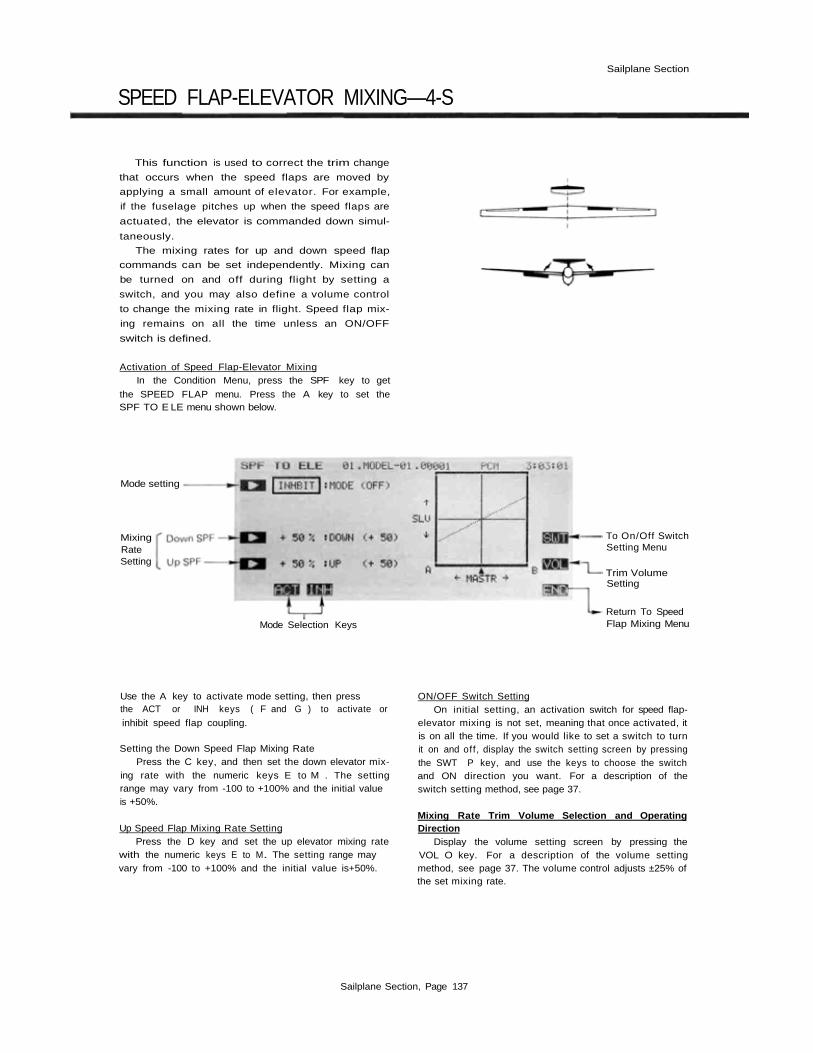
Sailplane Section
SPEED FLAP-ELEVATOR MIXING—4-S
This function is used to correct the trim change
that occurs when the speed flaps are moved by
applying a small amount of elevator. For example,
if the fuselage pitches up when the speed flaps are
actuated, the elevator is commanded down simul-
taneously.
The mixing rates for up and down speed flap
commands can be set independently. Mixing can
be turned on and off during flight by setting a
switch, and you may also define a volume control
to change the mixing rate in flight. Speed flap mix-
ing remains on all the time unless an ON/OFF
switch is defined.
Activation of Speed Flap-Elevator MixingIn the Condition Menu, press the SPF key to get
the SPEED FLAP menu. Press the A key to set theSPF TO E LE menu shown below.
Mode setting
MixingRateSetting
Mode Selection Keys
To On/Off SwitchSetting Menu
Trim VolumeSetting
Return To SpeedFlap Mixing Menu
Use the A key to activate mode setting, then pressthe ACT or INH keys ( F and G ) to activate or
inhibit speed flap coupling.
Setting the Down Speed Flap Mixing RatePress the C key, and then set the down elevator mix-
ing rate with the numeric keys E to M . The settingrange may vary from -100 to +100% and the initial valueis +50%.
Up Speed Flap Mixing Rate SettingPress the D key and set the up elevator mixing rate
with the numeric keys E to M. The setting range mayvary from -100 to +100% and the initial value is+50%.
ON/OFF Switch SettingOn initial setting, an activation switch for speed flap-
elevator mixing is not set, meaning that once activated, itis on all the time. If you would like to set a switch to turnit on and off, display the switch setting screen by pressingthe SWT P key, and use the keys to choose the switchand ON direction you want. For a description of theswitch setting method, see page 37.
Mixing Rate Trim Volume Selection and OperatingDirection
Display the volume setting screen by pressing theVOL O key. For a description of the volume settingmethod, see page 37. The volume control adjusts ±25% ofthe set mixing rate.
Sailplane Section, Page 137

Sailplane Section
SPEED FLAP-AlLERON MIXING—4-S
This mixing is used to make the ailerons oper-
ate together as speed flaps. When the speed flaps
are deployed, the speed flaps and ailerons all
perform the speed flap operation simultaneously.
The mixing rates for up and down speed flap
movement can be set independently. You may also
set up a switch for switching this mixing on and
off during flight. If this mixing is activated with-
out defining an ON/OFF switch, mixing remains
on all the time.
Activation of Speed Flap-Aileron MixingIn the Condition Menu, press the SPF key to get the
SPEED FLAP menu. Press the B key to get the SPF TOAIL menu shown below.
Mode setting
MixingRateSetting
To On/Off SwitchSetting Menu
Return To SpeedFlap Mixing Menu
Mode Selection Keys
Use the A key to activate mode setting, then pressthe ACT or INH keys ( F and G ) to activate orinhibit speed flap coupling.
Setting the Down Speed Flap Mixing RatePress the C key, and then set the down aileron mix-
ing rate with the numeric keys E to M . The initial valueis +50% and the setting range may vary from -100 to+100%.
ON/OFF Switch SettingOn initial setting, an activation switch for speed flap-
aileron mixing is not set, meaning that once activated, itis on all the time. If you would like to set a switch to turnit on and off, display the switch setting screen by pressingthe SWT P key, and use the keys to choose the switchand ON direction you want. For a description of theswitch setting method, see page 37.
Up Speed Flap Mixing Rate SettingPress the D key and set the up aileron mixing rate
with the numeric keys E to M . The setting range mayvary from -100 to +100% and the initial value is+50%.
Sailplane Section, Page 138
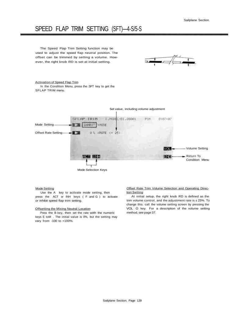
Sailplane Section
SPEED FLAP TRIM SETTING (SFT)—4-S/5-S
The Speed Flap Trim Setting function may be
used to adjust the speed flap neutral position. The
offset can be trimmed by setting a volume. How-
ever, the right knob RD is set at initial setting.
Activation of Speed Flap TrimIn the Condition Menu, press the SFT key to get the
SFLAP TRIM menu.
Set value, including volume adjustment
Mode Setting
Offset Rate Setting
Volume Setting
Return ToCondition Menu
Mode Selection Keys
Mode SettingUse the A key to activate mode setting, then
press the ACT or INH keys ( F and G ) to activateor inhibit speed flap trim setting.
Offsetting the Mixing Neutral LocationPress the B key, then set the rate with the numeric
keys E toM . The initial value is 0%, but the setting mayvary from -100 to +100%.
Offset Rate Trim Volume Selection and Operating Direc-tion Setting
At initial setup, the right knob RD is defined as thetrim volume control, and the adjustment rate is ± 25%. Tochange this. call the volume setting screen by pressing theVOL O key. For a description of the volume settingmethod, see page 37.
Sailplane Section, Page 139

Sailplane Section
BUTTERFLY MIXING (BFY)—4-S/5-S
Butterfly mixing, sometimes canned "crow"
mixing, is a way to get effective glide path control
without using spoilers. The butterfly action simul-
taneously raises the left and right ailerons and
lowers the speed flaps (brake flaps for 5-S).
The total travel can be adjusted by CH6 vol-
ume. The butterfly neutral position can be offset
from the center position. Butterfly mixing can be
turned on and off during flight by setting a switch.
If a switch is not set, mixing remains on all the
time.
5-S BUTTERFLY OPERATION
4-S BUTTERFLY OPERATION
Setting Up Butterfly MixingButterfly is often controlled with the throttle stick,
but at initiation the control is assigned to the left knobVR(A). The FNC command in the Model menu may beused to change the assignment. In that menu, select SF2with the J key, then press CTR. Select the throttle stickby choosing J3 with the K key (null the CTR for airbrakeABK if you want). At this time, be sure that bothailerons and speed flaps (or brake flaps for 5-S) move theproper directions. The default speed flap control is theleft slider. If you use speed flap-aileron mixing, this willbecome the camber control.
Activation of commandIn the Condition Menu, press the BFY key to get the
BUTTERFLY menu, as shown in the figure.
Mode SettingPress the A key to activate mixing, then press the
ACT or INH key ( F or G ) to activate or inhibit thebutterfly function. When you activate, you will noticetwo things: first, all four wing servos move, unless thethrottle stick happens to be at center. Second, the Alarmlight begins flashing. The alarm light is on whenever BFYis active. This is OK, except the transmitter will beep if itis on when first powered up. This is annoying, becauseyou can't stop it!
In just a moment, you will set the offset position forthe butterfly stick. The alarm light and beeping at startupmay be taken care of two ways: either an activationswitch may be defined, or the on position may be setslightly away from the zero-butterfly position. In thelatter case, the function is off until the stick is movedslightly.
Sailplane Section, Page 140
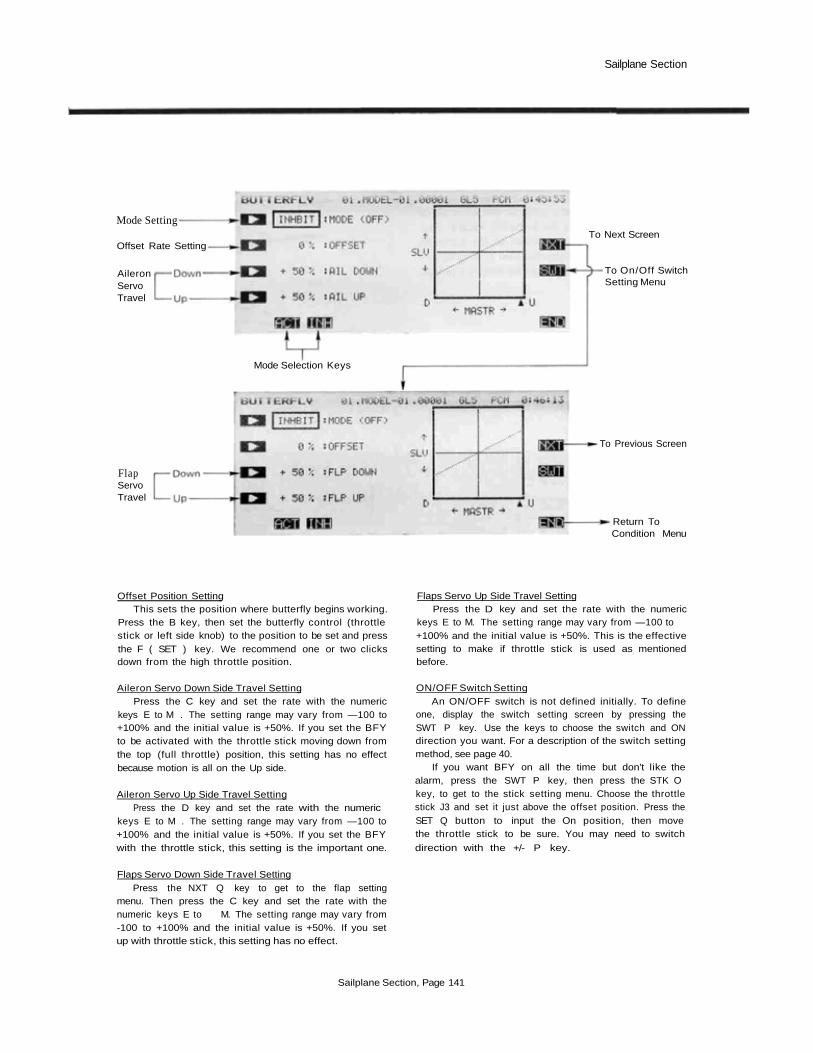
Sailplane Section
Mode Setting
Offset Rate Setting
AileronServoTravel
Mode Selection Keys
To On/Off SwitchSetting Menu
FlapServoTravel
To Previous Screen
Return ToCondition Menu
To Next Screen
Offset Position SettingThis sets the position where butterfly begins working.
Press the B key, then set the butterfly control (throttlestick or left side knob) to the position to be set and pressthe F ( SET ) key. We recommend one or two clicksdown from the high throttle position.
Aileron Servo Down Side Travel SettingPress the C key and set the rate with the numeric
keys E to M . The setting range may vary from —100 to+100% and the initial value is +50%. If you set the BFYto be activated with the throttle stick moving down fromthe top (full throttle) position, this setting has no effectbecause motion is all on the Up side.
Aileron Servo Up Side Travel SettingPress the D key and set the rate with the numeric
keys E to M . The setting range may vary from —100 to+100% and the initial value is +50%. If you set the BFYwith the throttle stick, this setting is the important one.
Flaps Servo Down Side Travel SettingPress the NXT Q key to get to the flap setting
menu. Then press the C key and set the rate with thenumeric keys E to M. The setting range may vary from-100 to +100% and the initial value is +50%. If you setup with throttle stick, this setting has no effect.
Flaps Servo Up Side Travel SettingPress the D key and set the rate with the numeric
keys E to M. The setting range may vary from —100 to+100% and the initial value is +50%. This is the effectivesetting to make if throttle stick is used as mentionedbefore.
ON/OFF Switch SettingAn ON/OFF switch is not defined initially. To define
one, display the switch setting screen by pressing theSWT P key. Use the keys to choose the switch and ONdirection you want. For a description of the switch settingmethod, see page 40.
If you want BFY on all the time but don't like thealarm, press the SWT P key, then press the STK Okey, to get to the stick setting menu. Choose the throttlestick J3 and set it just above the offset position. Press theSET Q button to input the On position, then movethe throttle stick to be sure. You may need to switch
direction with the +/- P key.
Sailplane Section, Page 141

Sailplane Section
BUTTERFLY TRIM Mix (BYE)-4-S/5-S
Butterfly trim mixing uses elevator motion to
correct any change in model attitude when butter-
fly is activated. The CH6 volume up side and down
side correction rates can be set independently.
The correction neutral position can be offset to
a point different from the butterfly neutral posi-
tion, but it should be matched to the butterfly
mixing offset point. Butterfly trim mixing can be
turned on and off during flight by setting a switch.
5-S
4-S
Setting Up Butterfly Trim MixingActivation of command
In the Condition Menu, press the BYE key to get theBFY TO ELE menu as shown below.
Mode setting
Offset Setting
CorrectionRateSetting
To On/Off SwitchSetting Menu
Return ToCondition Menu
Mode Selection Keys
Mode SettingUse the A key to activate mode setting, then
press the ACT or INH keys ( F and G) to activateor inhibit butterfly trim mixing.
Offsetting the Mixing Neutral LocationPress the B key. Then set the butterfly control to the
desired offset position (usually where it begins working)and press the SFT F key.
Down Side Correction Rate SettingPress the C key and set the rate with the numeric
keys E to M . The setting range may vary from —100 to+100% and the initial value is +50%. If you use BFY onthrottle as described previously, this may not do anything.
Up Side Correction Rate SettingPress the D key and set the rate with the numeric
keys E to M . The setting range may vary from —100 to+100% and the initial value is +50%.
ON/OFF Switch SettingAn ON/OFF switch is not defined initially, so the
mixing will be on all the time. To define one, display theswitch setting screen by pressing the SWT P key. Usethe keys to choose the switch and ON direction you want.For a description of the switch setting method, see page
37.
Sailplane Section, Page 142

Sailplane Section
ELEVATOR TRIM (ETM)—2-S/5-S
The two Elevator Trim functions program an
elevator offset position which may be called by a
switch, for example to set the elevator position for
thermalling or cruising. The two offsets may be
set independently. Elevator trim 2 has priority.
To prevent a sudden trim change when the
elevator trim is switched, a delay time can be
entered. The amount of offset may be changed in
flight by moving a volume control.
Activation of commandIn the Condition Menu, press the ETM key to get the
ELE TRIMS menu, as shown in the figure.
Mode SettingThe same procedure is used to program both Trim 1
and Trim 2 settings. To switch between the elevator trim1 and 2 setting screens, press the NXT Q key.
Press the A key to activate mixing, then press theACT or INH key ( F or G ) to activate or inhibit theelevator trim function.
Elevator Trim 1 Setting Screen
Mode Setting
Delay rate setting
Offset Rate Setting
Mode Selection Keys
To Next Screen
To On/Off SwitchSetting Menu
Volume Setting
Return ToCondition Menu
To Previous Screen
Return ToCondition Menu
Set Value, Including Volume Control
Sailplane Section, Page 143

Sailplane Section
Delay Rate SettingPress the C key and enter the rate with the numeric
keys F to M . The delay may vary from 0 to 100% (theinitial value is 0%). A 100% delay takes about five secondsto move full travel.
Entering the Preset PositionPress the D key and set the rate with the numeric
keys E to M . The setting range may vary from —100 to+100% and the initial value is 0%. Press the number youwant. Caution: use small numbers as elevator trim changesare very effective!
ON/OFF Switch SettingAn ON/OFF switch is not defined initially. To define
one. display the switch setting screen by pressing theSWT P key. Use the keys to choose the switch and ONdirection you want. For a description of the switchsetting method, see page 37.
Mixing Rate Trim Volume Selection and OperatingDirection
A mixing rate volume control is not defined initially.To define one, display the volume setting screen bypressing the VOL O key. For a description of thevolume setting method, see page 37. The volume controladjusts ± 25% of the set mixing rate.
Sailplane Section, Page 144
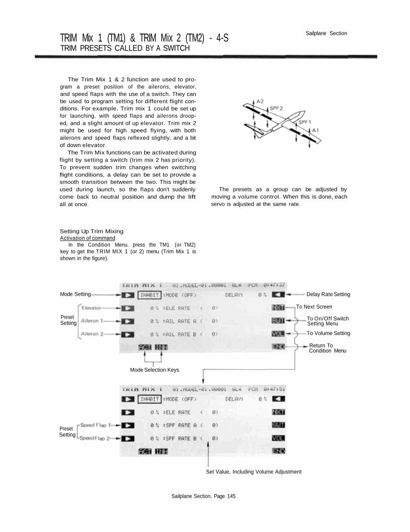
TRIM Mix 1 (TM1) & TRIM Mix 2 (TM2) - 4-STRIM PRESETS CALLED BY A SWITCH
Sailplane Section
The Trim Mix 1 & 2 function are used to pro-gram a preset position of the ailerons, elevator,and speed flaps with the use of a switch. They canbe used to program setting for different flight con-ditions. For example. Trim mix 1 could be set upfor launching, with speed flaps and ailerons droop-ed, and a slight amount of up elevator. Trim mix 2might be used for high speed flying, with bothailerons and speed flaps reflexed slightly, and a bitof down elevator.
The Trim Mix functions can be activated duringflight by setting a switch (trim mix 2 has priority).To prevent sudden trim changes when switchingflight conditions, a delay can be set to provide asmooth transition between the two. This might beused during launch, so the flaps don't suddenlycome back to neutral position and dump the liftall at once.
The presets as a group can be adjusted bymoving a volume control. When this is done, eachservo is adjusted at the same rate.
Setting Up Trim MixingActivation of command
In the Condition Menu. press the TM1 (or TM2)key to get the TRIM MIX 1 (or 2) menu (Trim Mix 1 isshown in the figure).
Mode Setting
PresetSetting
Mode Selection Keys
Delay Rate Setting
To Next Screen
To On/Off SwitchSetting Menu
To Volume Setting
Return ToCondition Menu
PresetSetting
Set Value, Including Volume Adjustment
Sailplane Section, Page 145

Sailplane Section
Mode SettingPress the A key to activate mixing, then press the
ACT or INH key ( F or G ) to activate or inhibit thetrim mix 1 (or 2) function. Now you will input thedesired presets for the elevator, ailerons, and speed flaps.
Setting the Elevator Preset AmountPress the B key and set the rate with the numeric
keys E to M. The initial preset value is set to 0%, butmay vary from -100 to +100%.
Entering the Aileron 1 Servo Preset AmountPress the C key and set the rate with the numeric
keys E to M . The setting range may vary from -100 to+100% and the initial value is 0%.
Aileron 2 Servo Preset InputtingPress the D key and set the rate with the numeric
keys E to M , as before. If your linkages and horns areidentical, this setting should be the same as for Aileron 1.
Speed Flap 1 PresetTo get to the Flap preset inputting menu, press the
NXT Q key. Then press the C key and set the ratewith the numeric keys E to M. As with the ailerons, theinitial value is set to 0%, but may vary from -100 to+100%.
Speed Flap 2 PresetPress the D key and set the rate with the numeric
keys E to M, as before. If your linkages and horns areidenticalM, this setting should be the same as for SpeedFlap 1.
Delay Rate SettingPress the R key and set the rate with the numeric
keys F to M. The initial delay is set to 0%, but mayvary from 0 to 100%. A 100% delay takes about fiveseconds to complete changing.
ON/OFF Switch SettingAn ON/OFF switch is not defined initially. To define
one, display the switch setting screen by pressing theSWT P key. Use the keys to choose the switch and ONdirection you want. For a description of the switch settingmethod, see page 37.
We recommend using the three-position switch forTrim Mix activation. The lower position is usually definedto be the launch mode (use TM1), middle position isnormal, and the upper position is used for the speedsettings (use TM2).
If you use the three position switch, you will want toactivate Trim mix on the middle position also. This willgive the delay in switching both to and From the trimmix.
Trim Volume Control and Direction SettingYou may adjust all the presets as a group, but a
volume control is not defined initially. Call the volumesetting screen by pressing the VOL O key. The volumesetting method is described on page 37. The volume con-trol adds or subtracts ± 25% from all the preset positions.
Sailplane Section, Page 146

Sailplane Section
FLAP-ELEVATOR Mix (F-E)—2-S
This function is used to compensate for trim
changes when flaps are deployed for slow flight or
landing by mixing in a small movement of elevator.
The elevator should be adjusted to move only a
small deflection amount: too much elevator can
make the model difficult to control.
The amount of correction can be adjusted
separately for both positive and negative flap in-
puts, and the neutral mixing position can be offset
from the flap neutral position. Flap-to-elevator
mixing can be turned on and off during flight by
setting a switch, but if an ON/OFF switch is not
set, it remains on all the time. The amount of mix-
ing can be changed by setting a volume control.
Setting Up Flap-to-Elevator MixingActivation of command
In the Condition Menu. press the F->E key to get theFLP TO ELE menu shown below.
Use the A key to activate mode setting, then press.the ACT or INH keys ( F and G ) to activate orinhibit flap-to-elevator coupling.
Offset Position SettingUse the B key to activate offset setting mode.
Then set the flap control to the offset position, and pressthe SET key F to store the desired position in mem-ory.
Setting the Mixing Ratio — Down and Up SideYou now set the amount of mixing for down flap
command. Press the C key to activate mixing ratio forthe down direction and set the value with the numerickeys E to M The number keys 0 through 100 inputthe value directly. The + and - keys increase or de-crease the value by 1. The +/- key may be used toreverse the throw direction. Your setting may vary from-100 to +100%, the initial value is set to +50%.
Now set the amount of mixing for the up flap com-mand. Press the D key to activate mixing ratio for theUp direction and set the throw with the numeric keys asbefore.
On/Off Switch SettingInitially an activation switch for is not set, meaning
that once activated, this function is on all the time. If youwould like to set a switch to turn it on and off , call theSwitch Setting screen by pressing the VOL O key.Then use the keys to choose the desired switch locationand on direction. For more information on the switchsetting method, see page 37.
Trim volume settingYou may set up the Flap-to-Elevator mixing so that its
effect may be changed in flight by moving a trim control.The trim control allows you to adjust the volume within± 25% of the set mixing rate, which can be handy forgetting the best value while flying the model. This optionis not activated at initial setup.
Call the volume setting screen by pressing thekey, and select the desired control using the screen
menus (for a description of the volume setting method,see page 37).
Use the END ( N ) key to leave this menu.
Sailplane Section, Page 147

Sailplane Section
ELEVATOR-FLAP Mix (E-F)—2-S
This mixing is used to droop the flaps whenever
an up elevator command is given (and may be
set up for down elevator as well, helpful during
'outside' maneuvers). It helps aerobatic aircraft to
make tight, square corners in maneuvers.
Elevator-to-flap mixing can be set up to be
turned on and off during flight by a switch (if no
switch is activated, this mixing remains on all the
time). You can also set the flap trim rate in this
function. If the flaperon function is activated, the
elevators are mixed with the ailerons, otherwise,
the mixing is with the flaps only.
Setting Up Elevator-to-Flap MixingActivation of command
In the Condition Menu, press the E->F key to get theELE TO FLP menu shown below. Use the A keyto activate mode setting, then press the ACT or INHkeys (F and G) to activate or inhibit Elevator-to-Flap.
Mixing State
Mode setting
Mixingratesetting
ON/OFF switchsettingTrimming volumesetting
Return to Conditionscreen
Set Value. Including Volume Adjustment
Mode Selection
Setting the Mixing Ratio - Down and Up SideYou now set the amount of mixing for down elevator
command. Press the C key to activate mixing ratio forthe Down direction and set the value with the numerickeys E to M . The number keys 0 through 100 inputthe value directly. The + and - keys increase or de-crease the value by 1. The +/- key may be used toreverse the throw direction. Your setting may vary from-100 to +100%, the initial value is set to +50%.
Now set the amount of mixing for the up elevatorcommand. Press the D key to activate mixing ratio forthe Up direction and set the throw with the numeric keysas before.
On/Off Switch SettingOn initial setting, the activation switch for Elevator-to-
Flap mixing is set as SW C on at the upper position. Ifyou would like to change the switch or turn mixing on allthe time, call the Switch Setting screen by pressing theSWT P key. Then use the keys to choose the desiredswitch location and on direction. For more informationon the switch setting method, see page 37).
Mixing Rate Trim Volume Selection and OperatingDirection
A mixing rate volume control is not defined initially.To define one, display the volume setting screen bypressing the VOL O key. For a description of thevolume setting method, see page 37. The volume controladjusts ±25% of the set mixing rate.
Use the END ( N) key to leave this menu.
Sailplane Section, Page 148

Sailplane Section
FLAPERON MIXING (FPN)—2-S
This function allows you to program theailerons to work in the same direction, giving aflap response as well as aileron control (see figure).For good square maneuvers, and landing, bothailerons can be raised and lowered simultaneously.While this function is on, regular aileron operationis always present.
The Flaperon function requires two separatechannels: Receiver CH1 (aileron 1/flap 2) and CH5(aileron 2/flap 1) are the operating channels. TheAileron 1 and Aileron 2 left and right deflectionangles can be adjusted independently making iteasy to apply differential to the ailerons. Withdifferential, the up side travel is set to around 5%larger than the down travel.
You may also adjust the Flap 1 and Flap 2throws independently, and you can set the flaptrim rate as large or small as you like. Also, theflap trim offset can be adjusted, allowing you to
Flap operation
Aileron operation
freely change the flap neutral angle.When setting aileron differential with this func-
tion, set the trim volume at the aileron differential(ADF) function setting screen.
Setting Up FlaperonsActivation of command
In the Condition Menu, press the FLP key to get theFLAPERON menu as shown below. Use the A keyto activate mode setting, then press the ACT F key to
activate. Next, press the E ( YES ) key. This auto-matically deactivates ( INH ) the aileron differential( ADF ) function.
Deactivate mixing by pressing the INH key G toinhibit the function.
Sailplane Section, Page 149

Sailplane Section
Setting the Aileron 1 TravelYou now set the left-side travel for Aileron 1. Press the
B key to activate left travel setting for Aileron 1 and setthe travel with the numeric keys E to M . The numberkeys 0 through 100 input the value directly. The +and - keys increase or decrease the value by 1. The+/- keys may be used to reverse the throw direction.
If you are not sure what you are changing, hold thestick to one side and press different keys — if there is noeffect, move the aileron stick to the other side and con-tinue. Your setting may vary from —120 to +120%, withan initial value of +100%.
Now set the right-side travel for Aileron 1. Press theQ key to activate Aileron 1 right travel setting and setthe travel with the numeric keys as before.
Setting the Aileron 2 TravelsThis procedure is repeated for Aileron 2. Press the C
key to activate left travel setting for Aileron 2 and set thetravel with the numeric keys E to M as before.
Now set the right-side travel for Aileron 2. Press the13 key to activate Aileron 2 right travel setting and setthe travel as before.
Setting the Flap Travels — 1 and 2You now set the travel for Flap 2. Press the D key to
activate travel setting for Flap 2 and set the travel withthe numeric keys E to M. Your setting may vary from-100 to +100%, with an initial value of +100%.
Now set the travel for Flap 1. Press the O key toactivate Flap 1 travel setting and set its travel with thenumeric keys. Its initial value is —100%.
Flap Trim Offset SettingFlap trim offset sets the flap position from which
motion occurs. To input the flap trim offset amountsetting, move to the next screen by pressing the NXT Rkey. Next, press the B key, then set the flap trim (left-side lever, LS) to the position to be set and press the
F (SET) key.
Flap Trim Authority SettingIn the Flaperon mode, Flap Trim moves both ailerons
upwards or downwards together. To input the Flap TrimAuthority. Press the C key and set the rate with thenumeric keys F to M. You may choose any value from0% to 100% for the Flap Trim Authority. The initialsetting is 30%, but a smaller number is recommended.
Sailplane Section, Page 150

FUTABA PCM1024ZA/ZH MENU GLOSSARY
Home Screen [HOM]S/S. . . . . .Start/Stop TimerRST . . . . .Reset timerTRM. . . . .Show trim menuCHD. . . . .Condition HoldTIM . . . . .To timer menuVLT . . . . .To voltmeter menuTAC . . . . .To tach menuT/R. . . . . .Timer resetSYS . . . . .To system menuMDL. . . . .To model menuCND . . . . .To condition menu
Other CommandsACT . . . . .ActivateA U T. . . . .AutoEND . . . . .Return to prev. menuINH . . . . .InhibitLIN . . . . .LinearLST . . . . .Last part of listMAN. . . . .ManualN X T . . . . .Next menuPRE . . . . .Previous menuPT-> . . . . .Next point to right<-PT . . . . .Next point to leftRST . . . . .Reset menuSEL . . . . .SelectSET . . . . .Yes, command is okSRV . . . . .ServoSWT . . . . .To switch set menuVOL . . . . .To volume set menu[+/-]. . . . .Change sign[ + ] . . . . ..Add1[ - ] . . . . . .Subtract 1[nnn]. . . . .Inputs number 'nnn'
Transmitter AbbreviationsJ1. . . . . . .Right stick horizontalJ2. . . . . . .Right stick verticalJ3. . . . . . .Left stick verticalJ4. . . . . . .Left stick horizontalRS . . . . . .Right sliderLS . . . . . .Left sliderRD. . . . . .Right dial VR(A)LD . . . . . .Left dial VR(B)SW(n) . . . .Switch No. (n)
System Menu [SYS]MSL . . . . .Model SelectionVLT . . . . .Voltmeter
OFF . . . .No load250. . . . .250 mA load
500. . . . .500 mA loadTAC . . . . .TachometerDSP . . . .Display on/offSRV . . . . .Servo Test & Bar Graph DisplayON . . . . .Activate functionOFF . . . .switch offTRN . . . . .Trainer System/Cmd.MIX . . . .Mix trainer commandsDTN . . . . .Data TransferTRN . . . .Transmit model dataRCV . . . .Receive model dataCPM . . . . .Copy ModelCPC . . . . .Copy ConditionPAR . . . . .ParametersUNA. . . . .User Name Def.ENT . . . .Enter letter at cursorFRQ. . . . .Transmitter Frequency Setting
(Syn. only)ABT . . . .Abort setting
Model Menu [MDL]CSL . . . . .Condition SelectTIM . . . . .Timer FunctionUP . . . . -Set timer count upDWN. . . .Set timer countdownS/S. . . . .Start/Stop timerRST . . . .Reset timerF/S . . . . . .Failsafe FunctionBFS . . . .Battery FailsafeNOR. . . .Hold last commandPMD . . . . .Pulse ModePCM . . . .Pulse code modulationPPM . . . .Pulse position modulation (FM)REV. . . . .Servo Reversing
Rev. selected servoFNC . . . . .Function ChangeTRM. . . .Trim tabCTR . . . .Control stick/knobRST . . . . .Data ResetCUT . . . . .Engine Cut
CHD. . . . .Condition HoldTYP . . . . .Model Type SelectionCH9 . . . . .Channel 9 SwitchMNA. . . . .Model Name Def.ALT . . . . .Alternate SwitchTHR . . . . .Throttle CurveSWH . . . . .Swashplate Type
S-1 . . . . .Normal swashS-2,4. . . .Mixed swash type 2,4SN3 . . . .Swash type SN3SR3 . . . .Swash typeSR3
Sailplane Section, Page 151

RDR. . . . .Rotor DirectionCW. . . . .ClockwiseCCW. . . .CounterclockwiseINV . . . . .Inverted PitchPIT. . . . . .Pitch Curve
Common Conditions |CND]CSL . . . . .Condition SelectATV . . . . .Adjustable travel volume/Chanel delayNOR. . . .NormalLIM . . . .LimitedAFR . . . . .Adjustable function rateD/R . . . . .Dual rateP M X . . . . .Programmable mixingSTM . . . . .Sub trimTOF . . . . .Trim offsetCNA. . . . .Condition namingTRM. . . . .Digital trim
T1-4 . . . .Trims 1-4C-M . . . .Current to memoryM-C . . . .Memory into currentATL . . . .Trim at low end onlyCMB. . . .Combined all conds.SEP . . . .Trim this cond. only
Model Type LabelsAIR . . . . .Airplane typeHEL . . . . .Helicopter typeGL2 . . . . .Sailplane 2 wing servosGL4 . . . . .Sailplane, 4 wing servosGL5 . . . . .Sailplane, 5 wing servo
Airplane MenuADF . . . . .Aileron DifferentialA->R. . . . .Aileron-»-Rudder MixingVTL . . . . .V-TailR->A. . . . .Rudder->Aileron MixingEVN . . . . .ElevonE->F . . . . .Elevator->Flap MixingF->E . . . . .Flap->Elevator MixingCPT . . . . .Collective PitchALV . . . . .AilevatorFPN . . . . .FlaperonABK . . . . .Air brakeSPO . . . .Spoiler control
AUT . . . .Automatic modeMAN. . . .Manual mode
SNP . . . . .Snap RollTCV . . . . .Throttle curve
Sailplane MenuADF. . . . .Ail. DifferentialA->R. . . . .Rudder Coupling
ASF . . . . .Ail.-Speed Flap MixingVTL . . . . .V-tail MixingABE . . . . .AirbrakeEBF . . . . .Elevators-Brake Flap MixingESF . . . . .Elevator-Speed Flap MixingBKF . . . . .Brake flapSPF . . . . .Speed FlapSFT . . . . .Flap Trim SettingBFY . . . . .ButterflyBYE . . . . .Butterfly Trim MixETM . . . . .Elevator Trim SetsTM1 . . . . .Trim set 1TM2 . . . . .Trim Set 2F->E . . . . .Flap-Elevator mixingE->F . . . . .Elevator-Flap MixingFPN . . . . .Flaperon Mixing
Helicopter MenuPCV . . . . .Pitch MixingPHV . . . . .Hovering PitchPTM . . . . .Pitch TrimTCV . . . . .Throttle CurveTHV. . . . .Hovering ThrottleHOF . . . . .Hovering OffsetHLD. . . . .Throttle HoldSWP . . . . .Swashplate TypeP->R . . . . .Pitch-RudderR->T. . . . .Rudder-ThrottleGYR. . . . .Gyro SensitivityACC . . . . .AccelerationINV . . . . .Inverted Pitch
Model Control Abbrevs.AIL . . . . .AileronAU1 . . . . .Aux Channel 1AU2 . . . . .Aux Channel 2BKF . . . . .Brake flapCH9 . . . . .Channel 9ELE . . . . .ElevatorFLP . . . . .FlapGEA. . . . .GearGYR. . . . .GyroPIT. . . . . .PitchRUD. . . . .RudderSF1 . . . . .Speed flap 1SF2 . . . . .Speed flap 2SPO . . . . .SpoilerTHR. . . . .Throttle
Misc. AbbreviationsSyn. . . . . .SynthesizedIndented listings are subcommands
Sailplane Section, Page 152
FutabaLIMITED WARRANTY
FUTABA CORPORATION OF AMERICA warrants this FUTABA Digital Proportional R/C System againstany detects in material or workmanship (or a period of one (1) year from the date of original consumer purc-hase. If the product becomes defective during this warranty period, FUTABA will repair it. or replace it atFUTABA'S discretion, without charge for parts or tabor, in accordance with the warranty service procedure de-scribed below This warranty extends only to the original consumer buyer and is not assignable or Iransferrableto any other person,
This Limited Warranty does not cover any damage to the product caused by faulty or leaking batteriesnot supplied by FUTABA, force major. accident, misuse, faulty installation, improper maintenance, or repair oralteration by unauthorized persons or agents. This Limited Warranty also does not cover any FUTABA productspurchased or used outside of the United Stales and Canada or in any of its territorial possessions.
Repair or replacement of the product is the SOLE AND EXCLUSIVE REMEDY for any loss or damage.no matter what form or how arising, due to a defect in a FUTABA product. THIS WARRANTY IS EXCLUSIVEAND IS IN LIEU OF ALL OTHER WARRANTIES, EXPRESS. IMPLIED OR STATUTORY. INCLUDING BUT NOTLIMITED TO ANY WARRANTIES OR MERCHANTABILITY OR FITNESS FOR A PARTICULAR PURPOSE, WITHALL IMPLIED WARRANTIES DISCLAIMED TO THE FULLEST EXTENT PERMITTED BY LAW AND IN NOEVENT TO EXCEED ONE YEAR Some slates do not allow limitations on how long an implied warranty lasts.so the above limitation may not apply to you.
FUTABA SHALL NOT BE LIABLE UNDER THIS LIMITED WARRANTY FOR ANY INCIDENTAL, CONS-EQUENTIAL. INDIRECT OR SPECIAL DAMAGES. INCLUDING WITHOUT LIMITATION, LOSS OF PROFITS OROTHER ECONOMIC DAMAGES Some stales do not allow the exclusion or limitation of incidental or conse-quential damages so that this above limitation or exclusion of incidental and consequential damages may notapply to you.
This Limited Warranty sets forth FUTABA'S entire warranty (or these products and may not be modifiedor supplemented by any written or oral statements by any person or in any other document. This Limited Wa-rranty gives you specific legal rights, and you may also have other rights which vary from state to stale
This Limited Warranty applies only to the Radio Contorol Equipment purchased and used in the UnitedStates of America (excluding its possessions and territories) and/or Canada-
WARRANTY SERVICE PROCEDUREWe urge you to complete and mail the attached registration card within thirty (30) days after the
original purchase date The information on this card will enable FUTABA to provide you with better serviceKeep the owner's portion along with your original bill of sale.
If you need service for your product under this Limited Warranty, you must deliver the product toFUTABA at the address noted below at your expense before the end of the warranty period. All transportation,postage and other charges to ship the product to FUTABA must be prepaid by you FUTABA will not acceptcollect or postage due shipments, FUTABA will also not be responsible for any damages occurring duringdelivery to FUTABA so you should safely and securely pack the product, preferably in its original carton Ofequivalent, and purchase insurance for the shipment. You should also include in the package a legible copyof the bill of sale and a written note which gives your name, return address and contact telephone number.a description of the product returned (model number, frequency, and serial number) and a full explanationof the problem FUTABA pays the cost of returning products serviced under this Limited Warranty.
Warranty returns should be sent to the following address:
SERVICE DEPARTMENT OF HOBBY R/CFUTABA CORPORATION OF AMERICA
4 STUDEBAKERIRVINE, CA 927 1 8
Printed in Japan/990606 *