Embed Size (px)
Citation preview
8/3/2019 Front Bumper Assembly
http://slidepdf.com/reader/full/front-bumper-assembly 1/14
Audi > A4, S4 (B6, B7) > 2002-2008Body Exterior63 - Removal and Installation
.
Front Bumper
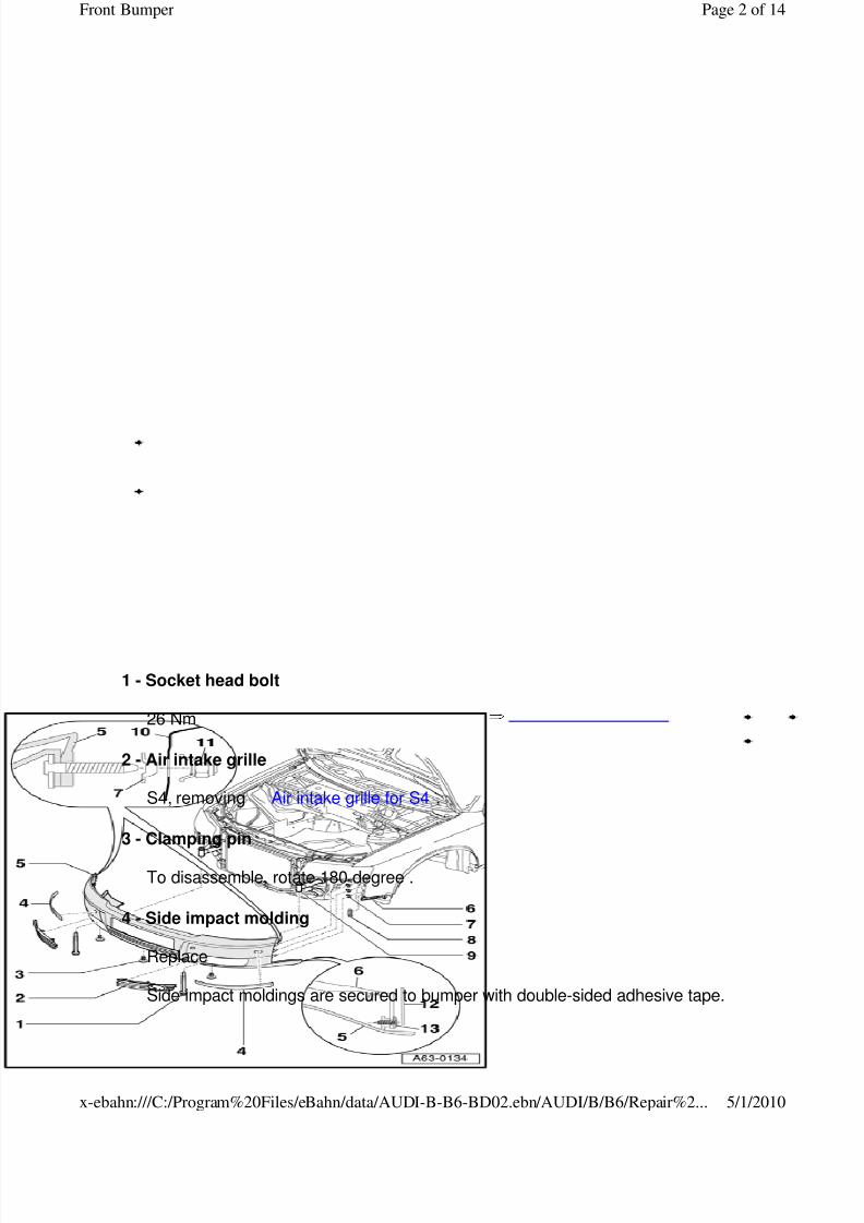
Special tools, testers and auxiliary items required
Socket T 40078
Use socket T 40078 to screw in cap nuts on fender bolts.
Assembly overview: up to Vehicle Identification Number (VIN) 400 000
Page 1 of 14Front Bumper
5/1/2010x-ebahn:///C:/Program%20Files/eBahn/data/AUDI-B-B6-BD02.ebn/AUDI/B/B6/Repair%2...
8/3/2019 Front Bumper Assembly
http://slidepdf.com/reader/full/front-bumper-assembly 2/14
8/3/2019 Front Bumper Assembly
http://slidepdf.com/reader/full/front-bumper-assembly 3/14
It is not possible to remove without destroying.
To remove, pull side impact molding away from bumper.
Remove any residual adhesive on bumper.
Installation on same bumper
Bumper must be free of dust and grease in adhesion area
Clean bumper using petroleum spirits or cleaning solution D 009 401 04.
Note:
Centering holes for centering pins for the exact installation of side impact moldings arealready present in bumper
Position centering pins with double-sided adhesive tape onto markings of side impactmolding Adhering centering pins on side impact molding .
Remove protective foil from double-sided adhesive tape for side impact molding.
Press side impact molding with attached centering pins firmly onto bumper over theentire surface.
Installing on new bumper
Note:
Centering holes for side impact molding must be drilled on the new bumper beforepainting.
Position centering holes for side impact moldings on bumper Side Impact MoldingCentering Holes .
Apply side impact moldings to bumper as described above.
5 - Bumper
With crossmember
Bumper, removing and installing Front Bumper
Removing and installing crossmember Front Bumper Crossmember
Separating two-piece bumper cover Front Bumper Cover, Separating
Positioning license plate mounting holes Positioning license plate mounting holes
Page 3 of 14Front Bumper
5/1/2010x-ebahn:///C:/Program%20Files/eBahn/data/AUDI-B-B6-BD02.ebn/AUDI/B/B6/Repair%2...
8/3/2019 Front Bumper Assembly
http://slidepdf.com/reader/full/front-bumper-assembly 4/14
6 - Guide piece
Removing and installing Guide Piece
7 - Expanding clip
6x
Must be inserted into fender before installing bumper cover
8 - Grommet
2x
Must be inserted into fender before installing bumper cover
9 - Shock absorber
self-aligns to correct height in crossmember Front Bumper Mounting to ShockAbsorber
10 - Fender
11 - Special nut
4 Nm
12 - Wheelhousing liner
13 - Bolt
1 Nm
2x
Assembly overview: as of Vehicle Identification Number (VIN) 400 001
Page 4 of 14Front Bumper
5/1/2010x-ebahn:///C:/Program%20Files/eBahn/data/AUDI-B-B6-BD02.ebn/AUDI/B/B6/Repair%2...
8/3/2019 Front Bumper Assembly
http://slidepdf.com/reader/full/front-bumper-assembly 5/14
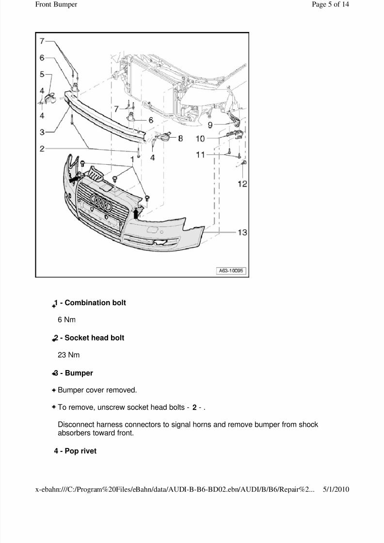
1 - Combination bolt
6 Nm
2 - Socket head bolt
23 Nm
3 - Bumper
Bumper cover removed.
To remove, unscrew socket head bolts - 2 - .
Disconnect harness connectors to signal horns and remove bumper from shockabsorbers toward front.
4 - Pop rivet
Page 5 of 14Front Bumper
5/1/2010x-ebahn:///C:/Program%20Files/eBahn/data/AUDI-B-B6-BD02.ebn/AUDI/B/B6/Repair%2...
8/3/2019 Front Bumper Assembly
http://slidepdf.com/reader/full/front-bumper-assembly 6/14
5 - Signal horn
To remove, drill off rivet heads.
6 - Support piece
Note:
When turning adjustment screw, make sure mounting bracket is raised
Before assembling bumper cover, adjustment screw for support piece must be adjustedAdjusting support piece
Tighten adjustment screw to 2 Nm with a long Torx wrench - T 30 - through holes incover - arrows - .
To disassemble, drill off pop rivet heads.
7 - Pop rivet
8 - Signal horn
9 - Brace for fender
10 - Guide piece
Side piece of bumper cover must be clipped in between fender and guide pieceRemoving guide piece
11 - Torx screw
1 Nm
12 - Combination screw
1 Nm
13 - Bumper cover
Note:
While installing, the following sequence described for assembling/bolting must be observed for correct assembly.
Set cover onto vehicle and first clip the left and right side piece into guide parts - 10 - .
Tighten cap nuts on fender bolts to 4 Nm Fender bolts .
Page 6 of 14Front Bumper
5/1/2010x-ebahn:///C:/Program%20Files/eBahn/data/AUDI-B-B6-BD02.ebn/AUDI/B/B6/Repair%2...
8/3/2019 Front Bumper Assembly
http://slidepdf.com/reader/full/front-bumper-assembly 7/14
Tighten bolts - 12 - to wheelhousing liner.
Loosely thread in bolts - 1 - .
Close hood and check cover for projection and recess.
If necessary, correct the cover position and tighten bolts -12
- to 6 Nm.
Tighten bolt on support piece to 2 Nm.
Bumper, removing and installing Front Bumper
Removing and installing crossmember Front Bumper Crossmember
RS 4 assembly overview
Note:
Removal and installation is performed as with standard production bumpers as of Vehicle Identification Number (VIN) 400 001.
Only differing steps are described.
Page 7 of 14Front Bumper
5/1/2010x-ebahn:///C:/Program%20Files/eBahn/data/AUDI-B-B6-BD02.ebn/AUDI/B/B6/Repair%2...
8/3/2019 Front Bumper Assembly
http://slidepdf.com/reader/full/front-bumper-assembly 8/14
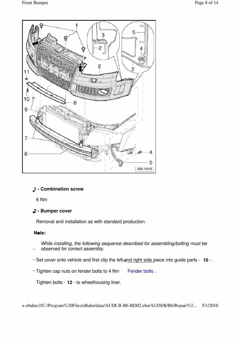
1 - Combination screw
6 Nm
2 - Bumper cover
Removal and installation as with standard production.
Note:
While installing, the following sequence described for assembling/bolting must be observed for correct assembly.
Set cover onto vehicle and first clip the left and right side piece into guide parts - 10 - .
Tighten cap nuts on fender bolts to 4 Nm Fender bolts .
Tighten bolts - 12 - to wheelhousing liner.
Page 8 of 14Front Bumper
5/1/2010x-ebahn:///C:/Program%20Files/eBahn/data/AUDI-B-B6-BD02.ebn/AUDI/B/B6/Repair%2...
8/3/2019 Front Bumper Assembly
http://slidepdf.com/reader/full/front-bumper-assembly 9/14
Loosely thread in bolts - 1 - .
Close hood and check cover for projection and recess.
If necessary, correct the cover position and tighten bolts - 12 - to 6 Nm.
Tighten bolt on support piece to 2 Nm Adjusting support piece .
Bumper, removing and installing Front Bumper
Removing and installing crossmember Front Bumper Crossmember
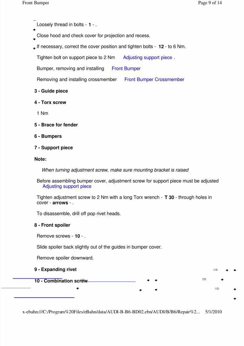
3 - Guide piece
4 - Torx screw
1 Nm
5 - Brace for fender
6 - Bumpers
7 - Support piece
Note:
When turning adjustment screw, make sure mounting bracket is raised
Before assembling bumper cover, adjustment screw for support piece must be adjustedAdjusting support piece
Tighten adjustment screw to 2 Nm with a long Torx wrench - T 30 - through holes incover - arrows - .
To disassemble, drill off pop rivet heads.
8 - Front spoiler
Remove screws - 10 - .
Slide spoiler back slightly out of the guides in bumper cover.
Remove spoiler downward.
9 - Expanding rivet
10 - Combination screw
Page 9 of 14Front Bumper
5/1/2010x-ebahn:///C:/Program%20Files/eBahn/data/AUDI-B-B6-BD02.ebn/AUDI/B/B6/Repair%2...
8/3/2019 Front Bumper Assembly
http://slidepdf.com/reader/full/front-bumper-assembly 10/14
2 Nm
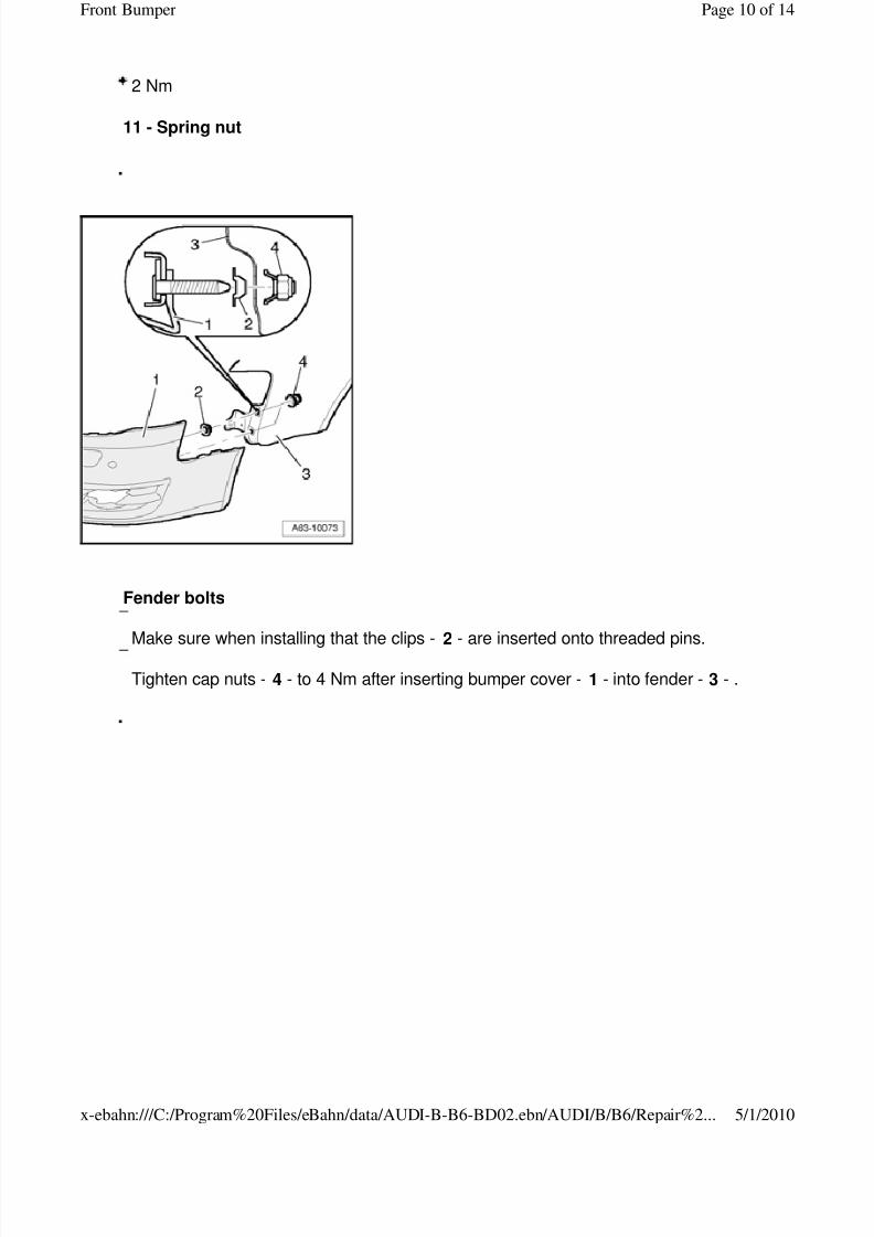
11 - Spring nut
.
Fender bolts
Make sure when installing that the clips - 2 - are inserted onto threaded pins.
Tighten cap nuts - 4 - to 4 Nm after inserting bumper cover - 1 - into fender - 3 - .
.
Page 10 of 14Front Bumper
5/1/2010x-ebahn:///C:/Program%20Files/eBahn/data/AUDI-B-B6-BD02.ebn/AUDI/B/B6/Repair%2...
8/3/2019 Front Bumper Assembly
http://slidepdf.com/reader/full/front-bumper-assembly 11/14
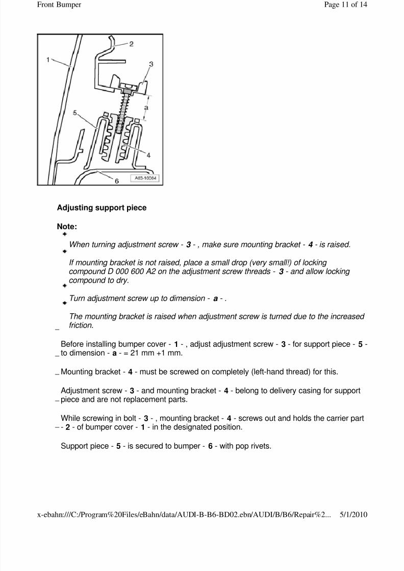
Adjusting support piece
Note:
When turning adjustment screw - 3 - , make sure mounting bracket - 4 - is raised.
If mounting bracket is not raised, place a small drop (very small!) of locking compound D 000 600 A2 on the adjustment screw threads - 3 - and allow locking compound to dry.
Turn adjustment screw up to dimension - a - .
The mounting bracket is raised when adjustment screw is turned due to the increased friction.
Before installing bumper cover - 1 - , adjust adjustment screw - 3 - for support piece - 5 -to dimension - a - = 21 mm +1 mm.
Mounting bracket - 4 - must be screwed on completely (left-hand thread) for this.
Adjustment screw - 3 - and mounting bracket - 4 - belong to delivery casing for support
piece and are not replacement parts.
While screwing in bolt - 3 - , mounting bracket - 4 - screws out and holds the carrier part- 2 - of bumper cover - 1 - in the designated position.
Support piece - 5 - is secured to bumper - 6 - with pop rivets.
Page 11 of 14Front Bumper
5/1/2010x-ebahn:///C:/Program%20Files/eBahn/data/AUDI-B-B6-BD02.ebn/AUDI/B/B6/Repair%2...
8/3/2019 Front Bumper Assembly
http://slidepdf.com/reader/full/front-bumper-assembly 12/14
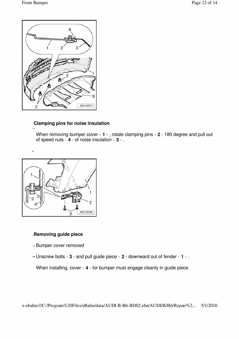
Clamping pins for noise insulation
When removing bumper cover - 1 - , rotate clamping pins - 2 - 180 degree and pull outof speed nuts - 4 - of noise insulation - 3 - .
.
Removing guide piece
Bumper cover removed
Unscrew bolts - 3 - and pull guide piece - 2 - downward out of fender - 1 - .
When installing, cover - 4 - for bumper must engage cleanly in guide piece.
Page 12 of 14Front Bumper
5/1/2010x-ebahn:///C:/Program%20Files/eBahn/data/AUDI-B-B6-BD02.ebn/AUDI/B/B6/Repair%2...
8/3/2019 Front Bumper Assembly
http://slidepdf.com/reader/full/front-bumper-assembly 13/14
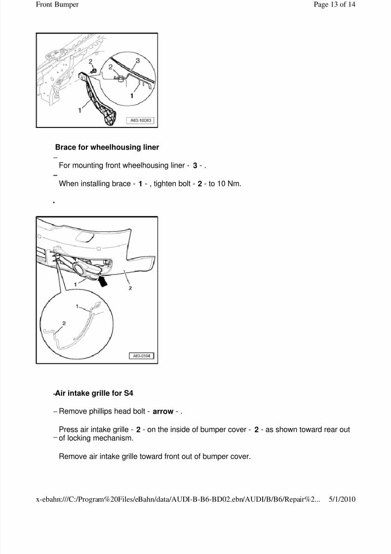
Brace for wheelhousing liner
For mounting front wheelhousing liner - 3 - .
When installing brace - 1 - , tighten bolt - 2 - to 10 Nm.
.
Air intake grille for S4
Remove phillips head bolt - arrow - .
Press air intake grille - 2 - on the inside of bumper cover - 2 - as shown toward rear outof locking mechanism.
Remove air intake grille toward front out of bumper cover.
Page 13 of 14Front Bumper
5/1/2010x-ebahn:///C:/Program%20Files/eBahn/data/AUDI-B-B6-BD02.ebn/AUDI/B/B6/Repair%2...
8/3/2019 Front Bumper Assembly
http://slidepdf.com/reader/full/front-bumper-assembly 14/14
Copyright © 2008 Audi of America, Inc. and Bentley Publishers. All rights reserved. Last processed:
Page 14 of 14Front Bumper