Embed Size (px)
Citation preview

GROUP 51
EXTERIORCONTENTS
FRONT BUMPER ASSEMBLY AND RADIATOR GRILLE. . . . . . . . . . . . . . 51-2
ADHESIVE . . . . . . . . . . . . . . . . . . . . . . . . . 51-2REMOVAL AND INSTALLATION . . . . . . . . 51-2DISASSEMBLY AND REASSEMBLY. . . . . 51-5
REAR BUMPER ASSEMBLY . . . . . . 51-7REMOVAL AND INSTALLATION . . . . . . . . 51-7
OVERFENDER <RALLIART Version-R> . . . . . . . . . . 51-11
ADHESIVE . . . . . . . . . . . . . . . . . . . . . . . . . 51-11REMOVAL AND INSTALLATION . . . . . . . . 51-11
MOULDINGS . . . . . . . . . . . . . . . . . . . 51-14SPECIAL TOOL . . . . . . . . . . . . . . . . . . . . . 51-14MOULDINGS . . . . . . . . . . . . . . . . . . . . . . . 51-14REMOVAL AND INSTALLATION . . . . . . . . 51-14
DOOR SASH TAPE . . . . . . . . . . . . . . 51-16SPECIAL TOOL . . . . . . . . . . . . . . . . . . . . . 51-16DOOR SASH TAPE . . . . . . . . . . . . . . . . . . 51-17REMOVAL AND INSTALLATION . . . . . . . . 51-17
SIDE AIR DAM. . . . . . . . . . . . . . . . . . 51-23ADHESIVE . . . . . . . . . . . . . . . . . . . . . . . . . 51-23SIDE AIR DAM . . . . . . . . . . . . . . . . . . . . . . 51-23REMOVAL AND INSTALLATION <EXCEPT RALLIART Version-R> . . . . . . . 51-23REMOVAL AND INSTALLATION <RALLIART Version-R> . . . . . . . . . . . . . . . 51-25
GARNISHES <RALLIART Version-R>. . . . . . . . . . 51-26
ADHESIVE . . . . . . . . . . . . . . . . . . . . . . . . . 51-26
REMOVAL AND INSTALLATION <RALLIART VERSION-R> . . . . . . . . . . . . . 51-26
TAILGATE SPOILER . . . . . . . . . . . . . 51-27ADHESIVE . . . . . . . . . . . . . . . . . . . . . . . . . 51-27REMOVAL AND INSTALLATION . . . . . . . . 51-27
WINDSHIELD WIPER AND WASHER. . . . . . . . . . . . . . . . . . . . . . . 51-28
SERVICE SPECIFICATION . . . . . . . . . . . . 51-28TROUBLESHOOTING . . . . . . . . . . . . . . . . 51-28ON-VEHICLE SERVICE . . . . . . . . . . . . . . . 51-28WINDSHIELD WIPER . . . . . . . . . . . . . . . . . 51-29REMOVAL AND INSTALLATION . . . . . . . . 51-29INSPECTION. . . . . . . . . . . . . . . . . . . . . . . . 51-31WINDSHIELD WASHER . . . . . . . . . . . . . . . 51-33REMOVAL AND INSTALLATION . . . . . . . . 51-33INSPECTION. . . . . . . . . . . . . . . . . . . . . . . . 51-35
REAR WIPER AND WASHER . . . . . . 51-36TROUBLESHOOTING . . . . . . . . . . . . . . . . 51-36ON-VEHICLE SERVICE . . . . . . . . . . . . . . . 51-36REAR WIPER AND WASHER . . . . . . . . . . 51-37REMOVAL AND INSTALLATION . . . . . . . . 51-37INSPECTION. . . . . . . . . . . . . . . . . . . . . . . . 51-38
MARK . . . . . . . . . . . . . . . . . . . . . . . . . 51-40REMOVAL AND INSTALLATION . . . . . . . . 51-40
DOOR MIRROR . . . . . . . . . . . . . . . . . 51-42TROUBLESHOOTING . . . . . . . . . . . . . . . . 51-42DOOR MIRROR . . . . . . . . . . . . . . . . . . . . . 51-42REMOVAL AND INSTALLATION . . . . . . . . 51-42INSPECTION. . . . . . . . . . . . . . . . . . . . . . . . 51-43

FRONT BUMPER ASSEMBLY AND RADIATOR GRILLEEXTERIOR51-2
FRONT BUMPER ASSEMBLY AND RADIATOR GRILLEADHESIVE
M1511000501021
Application Specified adhesiveFront three-diamond mark Double-sided tape: Generic products
18 mm width and 0.8 mm thickness
REMOVAL AND INSTALLATION M1511025400170
<EXCEPT RALLIART Version-R>
AC403339AE
4 4
44
4
5
Double-sided tape: Generic products [ 18 mm width and 0.8 mm thickness ]
Double-sided tape affixed location
Section A – A Section B – B
Section C – C Section D – D Section E – E
Clip
Front end centre member
Splash shield
Clip
Clip Front fender
Claw
Claw

FRONT BUMPER ASSEMBLY AND RADIATOR GRILLEEXTERIOR 51-3
AC405501
12
2
AB
3
4
5
A
A
B
B
E
E EE
C
C
D
D
Removal steps 1. Front under cover panel assembly2. Side under cover panel mounting
clips3. Splash shield mounting clips
• Fog lamp connector connection <vehicles with fog lamp>
4. Front bumper assembly5. Front bumper bracket
Removal steps (Continued)

FRONT BUMPER ASSEMBLY AND RADIATOR GRILLEEXTERIOR51-4
<RALLIART Version-R>AC402777AC511769
AC511768
B
AC402777AC511769
AC511768
1
2
2AB
3
4
5
A
AB
B
Section A – A SectionB – B
Bolt
Front end centre member
4
5
4
Screw
B
Removal steps 1. Front under cover panel assembly2. Side under cover panel mounting
clips and screw3. Splash shield mounting clips and
screw
• Fog lamp connector connection <vehicles with fog lamp>
4. Front bumper assembly5. Front bumper bracket
Removal steps (Continued)

FRONT BUMPER ASSEMBLY AND RADIATOR GRILLEEXTERIOR 51-5
DISASSEMBLY AND REASSEMBLY M1511025500155
<EXCEPT RALLIART Version-R>
AC601359
8
AB
9
3
9
10
1
2
2
6
7
5
6
4
Disassembly steps 1. Front bumper grille2. Front bumper side grille3. Front bumper cap4. Radiator grille assembly5. Front three-diamond mark6. Front bumper bracket
7. Front bumper nut8. Front fog lamp <vehicles with fog
lamp>9. Front fog lamp bezel <vehicles with
fog lamp>10. Front bumper face
Disassembly steps (Continued)

FRONT BUMPER ASSEMBLY AND RADIATOR GRILLEEXTERIOR51-6
<RALLIART Version-R>
AC51176911
AB
14
1
9
15
2
3
104
7
12
6
68
5
15
13
44
155 7Screw
Boss
B
A
B CC
Double-sided tape: Generic products [ 18 mm width and 0.8 mm thickness ]
View A: Double-sided tape affixed location Section B – B Section C – C
Boss Screw
Disassembly steps 1. Front bumper cover2. Front bumper bracket A3. Front bumper net4. Three-diamond mark5. Radiator grille assembly6. Front bumper bracket B7. RALLIART mark8. Front bumper nut9. Front bumper cap
10. Air dam skirt panel A11. Front fog lamp bezel <vehicles with
fog lamp>12. Front fog lamp <vehicles with fog
lamp>13. Front bumper extension14. Air dam skirt panel B15. Front bumper face
Disassembly steps (Continued)

REAR BUMPER ASSEMBLYEXTERIOR 51-7
REAR BUMPER ASSEMBLYREMOVAL AND INSTALLATION
M1511001901323
<EXCEPT RALLIART Version-R>
AC601386
1
1
2 3
12 2
AB
1
BC
N
A
A
CB
Section A – A Section B – B Section C – C
Clip
Clip
Claw
2 2
<From April, 2006> <Up to March, 2006>
Removal steps • Rear combination lamp (Refer to
GROUP 54A, Rear combination lamp P.54A-81).
<<A>> 1. Rear bumper assembly
2. Rear bumper side bracket>>A<< 3. Rear bumper support plate
Removal steps (Continued)

REAR BUMPER ASSEMBLYEXTERIOR51-8
REMOVAL SERVICE POINT<<A>>REAR BUMPER ASSEMBLY REMOVAL
CAUTIONWhen removing the rear bumper, wrap a protec-tive tape around the licence plate to avoid dam-age to the bumper with the licence plate.
AC403411AB
A
A
A
A
Section A – A
Rear bumper
Rear bumpercentre upper bracket
Slide the rear bumper assembly sideways, and remove it.
INSTALLATION SERVICE POINT>>A<<REAR BUMPER SUPPORT PLATE INSTALLATION
AC401752AE
Rear bumper harness (LH)
Rear bumper support plate (LH)
For rear bumper support plate (LH), a cutout for rear bumper harness installation is provided. Install the harness as shown in the illustration.

REAR BUMPER ASSEMBLYEXTERIOR 51-9
<RALLIART Version-R>
AC511776
Rearoverfender
6
8
6
5
7
9
8
9
4
138
AB
72
B
N
N
AA
AA
B
Section A – A Section B – B
ClipClaw
Removal steps • Rear combination lamp GROUP 54A,
Rear combination lamp P.54A-81).1. Licence plate lamp connector
connection<<A>> 2. Rear bumper assembly
3. Licence plate lamp assembly4. Rear bumper bracket
>>A<< 5. Rear bumper support plate<<B>> >>B<< 6. Rivet
7. Rear bumper side lower bracket8. Rear bumper face9. Rear bumper side bracket
NOTE: Refer to REMOVAL AND INSTALLATION <EXCEPT RALLIART Version-R> for the rear bumper assembly removal and rear bumper support plate installation.
Removal steps (Continued)

REAR BUMPER ASSEMBLYEXTERIOR51-10
REMOVAL SERVICE POINT<<B>> RIVETS REMOVAL
AC600336AB
Rivet
Drill
Rear bumperside lowerbracket
Use a drill (4.0 mm) to make a hole in the rivet to break it, and then remove the rivet.
INSTALLATION SERVICE POINT>>B<< RIVETS INSTALLATION
AC600337AB
Unit: mm
10.2
Ø4.0Ø8.0
Use a rivet tool to attach the rivet by the following procedure.1. Insert the rivet into the base material rear bumper
side lower bracket.2. Attach the rivet by using the rivet tool.

OVERFENDER <RALLIART Version-R>EXTERIOR 51-11
OVERFENDER <RALLIART Version-R>ADHESIVE
M1511000501452
Application Specified adhesiveFront / Rear/Rear door overfender
Double-sided tape: Generic productsa: 3.0 mm width and 1.2mm thicknessb: 0.8mm thickness
REMOVAL AND INSTALLATIONM1511024700178
AC511796
5
3
1
4
AB
C
C
D
D
A
AB
B
2
6
8
7
1 14
33
Boss
Section A – A Section B – B Section C – C Section D – D
Clip
Clip
Clip

OVERFENDER <RALLIART Version-R>EXTERIOR51-12
AC511797AB
a
bb
b b
b
b
a
a
a
a
E E
E
E
E
E
3
2,5,6,7
4
5
62
1
E
E
7
Double-sided tape: Generic products,a: 3.0 mm width and 1.2 mm thicknessb: 0.8 mm thickness
Double-sided tape affixed location
Section E – E
Removal steps • Side air dam (Refer to P.51-25)1. Front overfender2. Front overfender pad3. Rear overfender4. Rear door overfender
5. Rear overfender pad A6. Rear door garnish pad7. Rear overfender pad B
>>A<< 8. Rear door lower black-out tape (body side)
Removal steps (Continued)

OVERFENDER <RALLIART Version-R>EXTERIOR 51-13
INSTALLATION SERVICE POINT>>A<<REAR DOOR LOWER BLACK-OUT TAPE INSTALLATION1. INSTALLATION POSITION
AC600859AB
Door opening line
43.6 mm
A
A
Rear door lowerblack-out tape
Black-out tape1.7 mm
Rear overfenderinstallation hole
Section A – A Rear door overfender
Rearoverfender
CAUTION• The ambient temperature should be 20 to
38°C. Ensure that the working area is clean.• If ambient temperature is less than 15°C, heat
the black-out tape and application surface to a temperature of 20 to 30°C.
• Be careful that air bubbles are not formed under the black-out tape.
2. INSTALLATION PROCEDURE(1) Wipe the black-out tape application surface
and clean it with a rag moistened with isopropyl alcohol.
(2) Remove backing paper from the black-out tape, and apply the tape to the specified position.
(3) Remove an application tape from the black-out tape.
MOULDINGSEXTERIOR51-14
MOULDINGSSPECIAL TOOL
M1511000601578
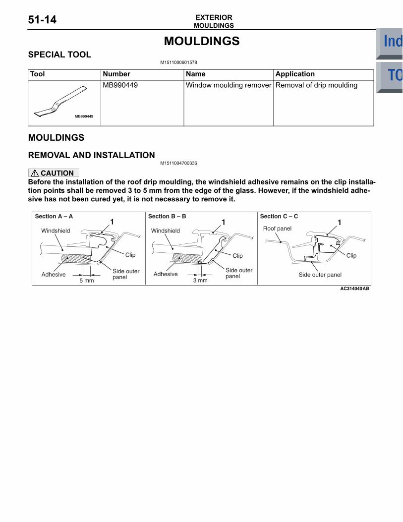
Tool Number Name Application
MB990449
MB990449 Window moulding remover Removal of drip moulding
MOULDINGS
REMOVAL AND INSTALLATIONM1511004700336
CAUTIONBefore the installation of the roof drip moulding, the windshield adhesive remains on the clip installa-tion points shall be removed 3 to 5 mm from the edge of the glass. However, if the windshield adhe-sive has not been cured yet, it is not necessary to remove it.
AC314040
1 1
Clip Clip
Section A – A Section B – B Section C – C
Clip
1
Side outer panel
Windshield Roof panelWindshield
Side outer panelSide outer panelAdhesive
5 mmAdhesive
3 mmAB

MOULDINGSEXTERIOR 51-15
AC314046
1
CC
AA
AB
BB
Roof drip moulding removal step
<<A>> 1. Roof drip moulding
REMOVAL SERVICE POINT<<A>> ROOF DRIP MOULDING REMOVAL
CAUTIONIf the moulding has become warped, it should not be reused.
AC313298ABMB990449
Use special tool window moulding remover (MB990449) to pry out the moulding.

DOOR SASH TAPEEXTERIOR51-16
DOOR SASH TAPESPECIAL TOOL
M1511000601589
Tool Number Name Application
MB990528
MB990528 Stripe tape spatula Door sash tape

DOOR SASH TAPEEXTERIOR 51-17
DOOR SASH TAPE
REMOVAL AND INSTALLATIONM1511024100110
Pre-removal and Post-installation Operation• Door Beltline Weather Strip Inner Removal and Installa-
tion (Refer to GROUP 42, Window Glass Runchannel and Door Opening Weatherstrip P.42-48).
• Door Opening Weather Strip Outer Removal and Installa-tion (Refer to GROUP 42, Window Glass Runchannel and Door Opening Weatherstrip P.42-48).
• Door Window Glass Runchannel Removal and Installation (Refer to GROUP 42, Window Glass Runchannel and Door Opening Weatherstrip P.42-48).
• Door Beltline Moulding Removal and Installation (Refer to GROUP 42, Window Glass Runchannel and Door Open-ing Weatherstrip P.42-48).
AC3135441
2
3
4
N
N
N
N
AB
Front door sash outer tape removal steps
<<A>> >>A<< 1. Door sash outer tape A<<A>> >>A<< 2. Door sash outer tape B
Rear door sash outer tape removal steps
<<A>> >>B<< 3. Door sash outer tape C<<A>> >>B<< 4. Door sash outer tape D

DOOR SASH TAPEEXTERIOR51-18
REMOVAL SERVICE POINT<<A>> DOOR SASH TAPES REMOVAL
CAUTIONPay attention to keep from getting burned by hot door panel or tapes.1. Use a hair drier to warm the tape.2. Peel the tip of the tape with your finger, and then
peel off the tape parallel to the application surface.
INSTALLATION SERVICE POINT>>A<< FRONT DOOR SASH OUTER TAPES INSTALLATION
CAUTION• The ambient temperature should be 20 to
30°C. Ensure that the working area is clean. Ideally, the tape application should be done at ambient temperature of 25°C.
• If ambient temperature is less than 15°C, heat the tape and application surface to a tempera-ture of 20 to 30°C. If ambient temperature is 35°C or higher, cool down them.
• The adhesive property of the tape is deterio-rated at low temperature, so the tape may come adrift easily. Meanwhile, it gets softened at hot temperature.
• When beginning to apply the tape, pay partic-ular attention. If the end of the tape cannot be applied to the specified position with an accu-racy of less than 1 mm, it may cause the poor appearance or adhesion.
•
AC303428
40 to 50˚
30 to 45˚
10 to 20 mm
10 to 20 mm
AB
MB990528
MB990528
Door sash tape
Door sash tape
Backing paper
Backing paper
<Pushing direction>
<Pulling direction>
3 to 7 cm/sec.
3 to 7 cm/sec.
DOOR SASH TAPEEXTERIOR 51-19
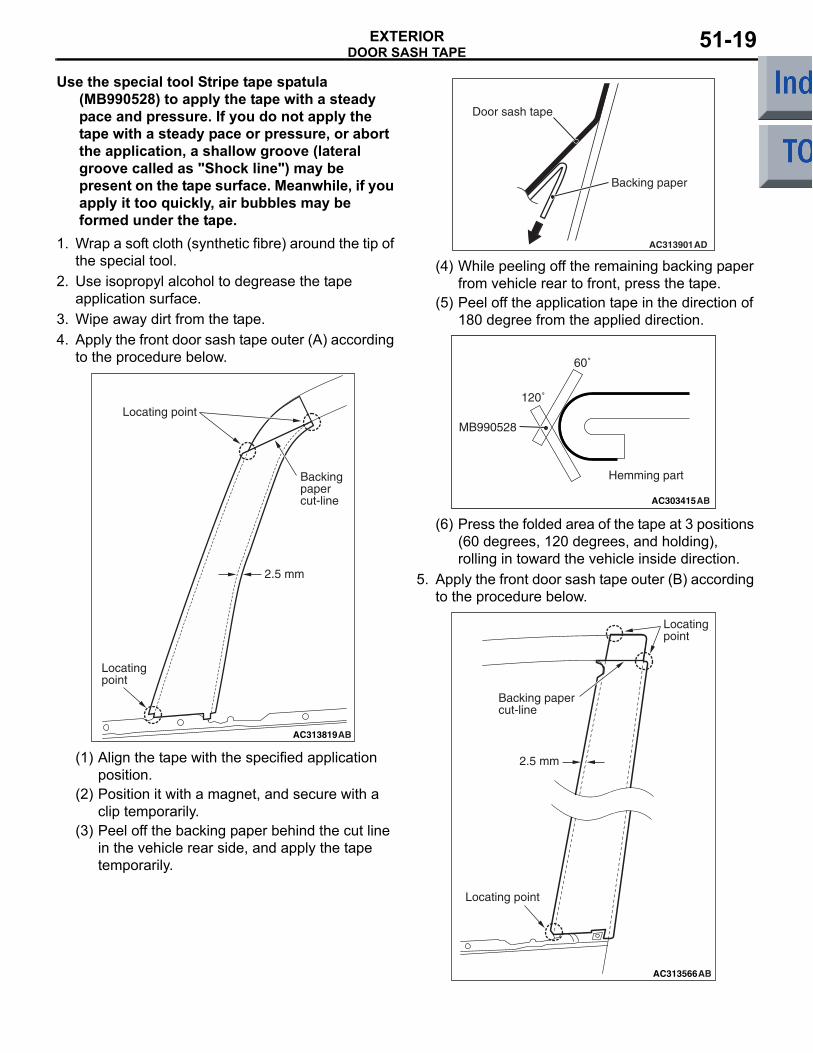
Use the special tool Stripe tape spatula (MB990528) to apply the tape with a steady pace and pressure. If you do not apply the tape with a steady pace or pressure, or abort the application, a shallow groove (lateral groove called as "Shock line") may be present on the tape surface. Meanwhile, if you apply it too quickly, air bubbles may be formed under the tape.
1. Wrap a soft cloth (synthetic fibre) around the tip of the special tool.
2. Use isopropyl alcohol to degrease the tape application surface.
3. Wipe away dirt from the tape.4. Apply the front door sash tape outer (A) according
to the procedure below.
AC313819AB
Locating point
2.5 mm
Backing papercut-line
Locating point
(1) Align the tape with the specified application position.
(2) Position it with a magnet, and secure with a clip temporarily.
(3) Peel off the backing paper behind the cut line in the vehicle rear side, and apply the tape temporarily.
AC313901
Door sash tape
AD
Backing paper
(4) While peeling off the remaining backing paper from vehicle rear to front, press the tape.
(5) Peel off the application tape in the direction of 180 degree from the applied direction.
AC303415AB
MB990528
120˚
60˚
Hemming part
(6) Press the folded area of the tape at 3 positions (60 degrees, 120 degrees, and holding), rolling in toward the vehicle inside direction.
5. Apply the front door sash tape outer (B) according to the procedure below.
AC313566AB
Locating point
Backing papercut-line
2.5 mm
Locating point

DOOR SASH TAPEEXTERIOR51-20
(1) Align the tape with the specified application position.
(2) Position it with a magnet, and secure with a clip temporarily.
(3) Peel off the backing paper in the upper area of the tape upward the cut line, and apply the tape temporarily.
AC313901
Door sash tape
AD
Backing paper
(4) While peeling off the remaining backing paper downward, press the tape.
(5) Peel off the application tape upward in the direction of 180 degrees.
AC303415AB
MB990528
120˚
60˚
Hemming part
(6) Press the folded area of the tape at 3 positions (60 degrees, 120 degrees, and holding), rolling in toward the vehicle inside direction.
>>B<< REAR DOOR SASH OUTER TAPES INSTALLATION
CAUTION• The ambient temperature should be 20 to
30°C. Ensure that the working area is clean. Ideally, the tape application should be done at ambient temperature of 25°C.
• If ambient temperature is less than 15°C, heat the tape and application surface to a tempera-ture of 20 to 30°C. If ambient temperature is 35°C or higher, cool down them.
• The adhesive property of the tape is deterio-rated at low temperature, so the tape may come adrift easily. Meanwhile, it gets softened at hot temperature.
• When beginning to apply the tape, pay partic-ular attention. If the end of the tape cannot be applied to the specified position with an accu-racy of less than 1 mm, it may cause the poor appearance or adhesion.
•
AC303428
40 to 50˚
30 to 45˚
10 to 20 mm
10 to 20 mm
AB
MB990528
MB990528
Door sash tape
Door sash tape
Backing paper
Backing paper
<Pushing direction>
<Pulling direction>
3 to 7 cm/sec.
3 to 7 cm/sec.
Use the special tool Stripe tape spatula with a steady pace and pressure. If you do not apply the tape with a steady pace or pressure, or abort the application, a shallow groove (lat-eral groove called as "Shock line") may be present on the tape surface. Meanwhile, if you apply it too quickly, air bubbles may be formed under the tape.
1. Wrap a soft cloth (synthetic fibre) around the tip of the special tool.

DOOR SASH TAPEEXTERIOR 51-21
2. Use isopropyl alcohol to degrease the tape application surface.
3. Wipe away dirt from the tape.4. Apply the door sash tape outer (C) according to
the procedure below.
AC313573AB
2.5 mm
Backing papercut-line
Backing papercut-line
Locating point
Locating point
Locating point
(1) Align the tape with the specified application position.
(2) Position it with a magnet, and secure with a clip temporarily.
(3) Peel off the backing paper in the upper area of the tape upward the cut line, and apply the tape temporarily.
AC313901
Door sash tape
AD
Backing paper
(4) While peeling off the remaining backing paper from vehicle rear to front, press the tape.
(5) Peel off the application tape upward in the direction of 180 degrees.
AC313587AB
Vertical surface
Corner
Horizontal surface
1
23
(6) Apply the tape to vertical surface (1), and peel off the remaining backing paper. Then apply the tape to corner (2) and horizontal surface (3) in that order.
AC303415AB
MB990528
120˚
60˚
Hemming part
(7) Press the folded area of the tape at 3 positions (60 degrees, 120 degrees, and holding), rolling in toward the vehicle inside direction.
DOOR SASH TAPEEXTERIOR51-22
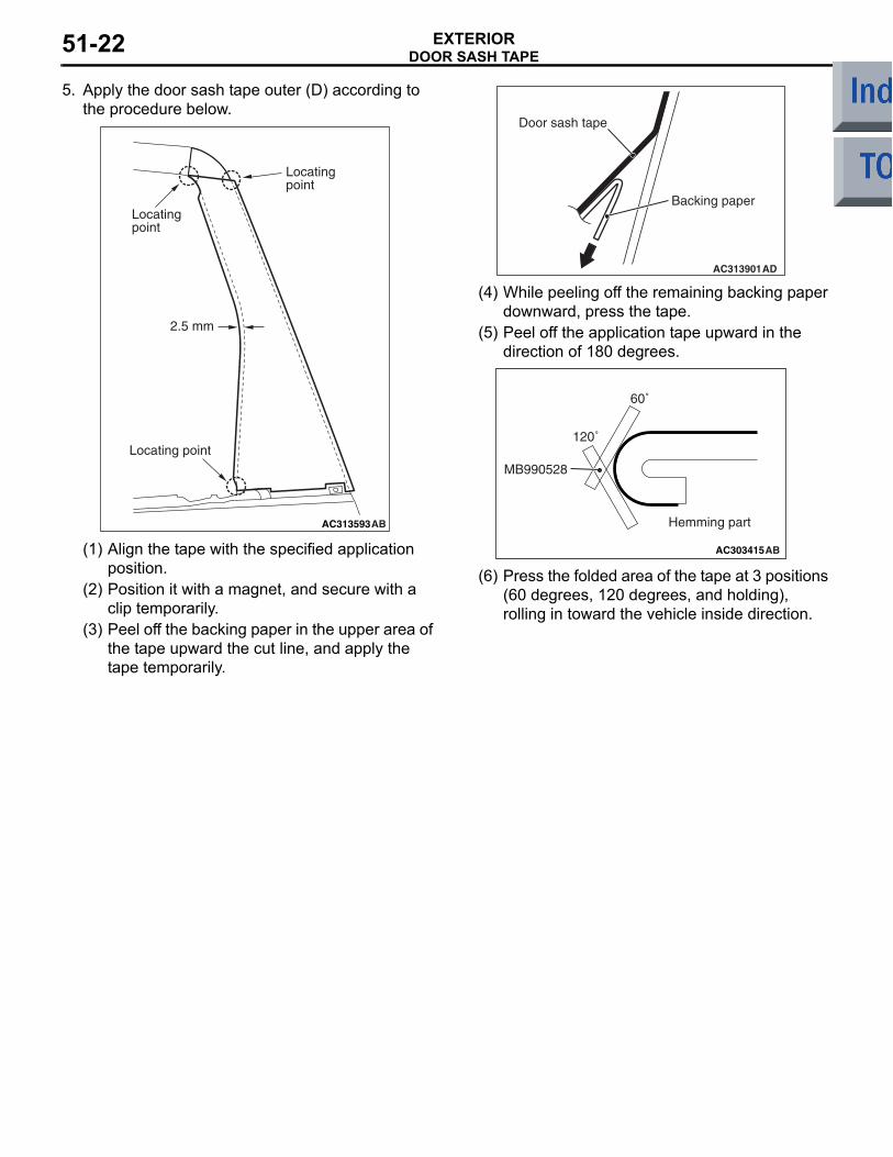
5. Apply the door sash tape outer (D) according to the procedure below.
AC313593AB
Locating point
Locating point
Locating point
2.5 mm
(1) Align the tape with the specified application position.
(2) Position it with a magnet, and secure with a clip temporarily.
(3) Peel off the backing paper in the upper area of the tape upward the cut line, and apply the tape temporarily.
AC313901
Door sash tape
AD
Backing paper
(4) While peeling off the remaining backing paper downward, press the tape.
(5) Peel off the application tape upward in the direction of 180 degrees.
AC303415AB
MB990528
120˚
60˚
Hemming part
(6) Press the folded area of the tape at 3 positions (60 degrees, 120 degrees, and holding), rolling in toward the vehicle inside direction.

SIDE AIR DAMEXTERIOR 51-23
SIDE AIR DAMADHESIVE
M1511000501010
Application Specified adhesiveSide air dam Double-sided tape: Generic products
4 mm width and 0.8 mm thickness
SIDE AIR DAMREMOVAL AND INSTALLATION <EXCEPT RALLIART Version-R>
M1511005500432
AC405461
AC4028791
AB
Double-sided tape affixed location
Double-sided tape: Generic products 4.0 mm width, 0.8 mm thickness
1
B
C
C
A
A
B
Clip
Clip
Side outer panel
Section A – A
Section B – B
Section C – C
1
1
1
Side outer panel
Front fender
Splash shield
Grommet
Screw
Removal <<A>> >>A<< 1. Side air dam

SIDE AIR DAMEXTERIOR51-24
REMOVAL SERVICE POINT<<A>> SIDE AIR DAM REMOVALGently lift and remove the side air dam. If there is any double-sided tape remaining on the side air dam, remove according to the following instructions.<Remove double-sided tape remaining on the body surface>
AC200049ABProtection tape
Double-sided tape
1. Attach protection tape all the way along the edges of the double-sided tape which is still adhering to the body.
AC200050AB
Double-sided tape
2. Scrape off the double-sided tape with a resin spatula as much as possible.
3. Peel off the protection tape.4. Wipe the body surface and clean it with a rag
moistened with isopropyl alcohol.
<Remove double-sided tape remaining on side air dam and adhere double-sided tape (when re-using side air dam)>
AC103187
1. Scrape off the double-sided tape on the side air dam with a resin spatula as much as possible.
2. Wipe the side air dam surface and clean it with a rag moistened with isopropyl alcohol.
3. Remove only a small portion of the residual adhesive.
4. Adhere the double-sided tape as specified on the side air dam (Refer to double-sided tape adherence location ).
INSTALLATION SERVICE POINT>>A<< SIDE AIR DAM INSTALLATION
AC103247
Backing paper
Adhesive tapeAC
1. Tear off the double-sided tape backing paper.NOTE: If attach the adhesive tape to the edge of the backing paper, it will be easy to tear off.
2. Install the side air dam.NOTE: If the double-sided tape is difficult to affix in cold temperature, etc., warm the bonding sur-faces of the body and side air dam to about 40− 60°C before affixing the tape.
3. Firmly press in the side air dam.
SIDE AIR DAMEXTERIOR 51-25
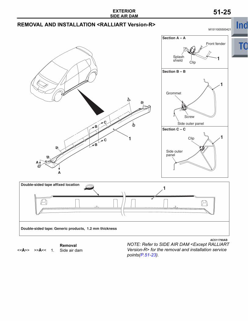
REMOVAL AND INSTALLATION <RALLIART Version-R>M1511005500421
AC511790
Grommet
Screw
1 1
1
1
1
AB
B
C
C
A
A
B
Clip
Clip
Side outer panel
Section A – A
Section B – B
Section C – C
Side outer panel
Front fender
Splash shield
Double-sided tape affixed location
Double-sided tape: Generic products, 1.2 mm thickness
Removal <<A>> >>A<< 1. Side air dam
NOTE: Refer to SIDE AIR DAM <Except RALLIART Version-R> for the removal and installation service points(P.51-23).
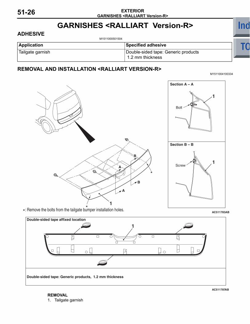
GARNISHES <RALLIART Version-R>EXTERIOR51-26
GARNISHES <RALLIART Version-R>ADHESIVE
M1511000501504
Application Specified adhesiveTailgate garnish Double-sided tape: Generic products
1.2 mm thickness
REMOVAL AND INSTALLATION <RALLIART VERSION-R>M1511004100334
AC511783
1
1
1
AB
A
B
*
*A
B
Section A – A
Section B – B
Bolt
Screw
: Remove the bolts from the tailgate bumper installation holes.*
AC511787AB
1Double-sided tape affixed location
Double-sided tape: Generic products, 1.2 mm thickness
REMOVAL 1. Tailgate garnish
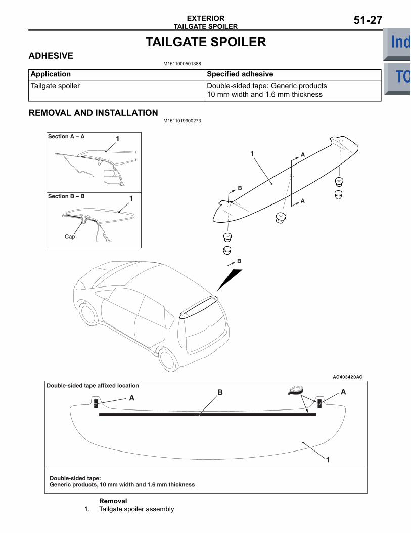
TAILGATE SPOILEREXTERIOR 51-27
TAILGATE SPOILERADHESIVE
M1511000501388
Application Specified adhesiveTailgate spoiler Double-sided tape: Generic products
10 mm width and 1.6 mm thickness
REMOVAL AND INSTALLATIONM1511019900273
AC403420AC
1
1
AB
A
A
1
1
B
B
A
Section A – A
Section B – B
Cap
Double-sided tape: Generic products, 10 mm width and 1.6 mm thickness
Double-sided tape affixed location
Removal 1. Tailgate spoiler assembly

WINDSHIELD WIPER AND WASHEREXTERIOR51-28
WINDSHIELD WIPER AND WASHERSERVICE SPECIFICATION
M1511000300596
Item Standard valueStop position of the windshield wiper arm/blade assembly (Distance between the edge of the wiper blade and the end of the deck garnish) mm
Drivers side: 40 ± 5Passengers side: 25 ± 5
TROUBLESHOOTINGM1511020000393
The windshield wiper and washer are controlled by the Smart Wiring System (SWS). For troubleshoot-ing, refer to GROUP 54B, Troubleshooting P.54B-35 or GROUP 54C, Troubleshooting P.54C-29.NOTE: Even when the ETACS-ECU has failed, the windshield wiper can work at low speed as fail-safe mode. (Normally, the windshield wiper operates when the ignition switch is at the "ACC" position. But, if it enters the fail-safe mode, the wiper can operate only when the ignition switch is at the "ON" position).
ON-VEHICLE SERVICEM1511000801022
WINDSHIELD INTERMITTENT WIPER INSPECTION1. Check the wipers operate in the intermittent
action when the windshield intermittent wiper switch is at the intermittent operation.
2. Check that the intermittent wiper interval is changed as the intermittent wiper knob is oper-ated.
3. Turn the windshield intermittent wiper switch to the intermittent operation position. Use the M.U.T.-III to set a simulated vehicle speed with the wiper knob held. The intermittent wiper inter-val should be changed as the simulated vehicle speed is changed.
4. If either of above is defective, carry out the trou-bleshooting. For troubleshooting, refer to GROUP 54B, Troubleshooting P.54B-35 or GROUP 54C, Troubleshooting P.54C-29.
WASHER MOTOR INSPECTION (WIND-SHIELD WASHER)
2 1
AC405556
1. Check the washer fluid level of washer tank located at front right corner, and refill fluid if necessary.
2. Remove the front part of splash shield (RH).3. Disconnect the washer motor connector.4. Connect the battery to the washer motor
connector as shown. Check that the washer motor delivers washer strongly.

WINDSHIELD WIPER AND WASHEREXTERIOR 51-29
WINDSHIELD WIPER
REMOVAL AND INSTALLATIONM1511007900577
AC313851
View A Section B – B
Section C – C
Section D – D
5
Windshield
5
Clip a
5
Clip b
Clip b
Clip a
4
AC
21
3
28 ± 5 N·m
4
5
A
8
6
7
7.4 ± 1.5 N·m
D
D
Claw
C
C
B
B
Note: Clip a positions : Clip b positions : Claw positions

WINDSHIELD WIPER AND WASHEREXTERIOR51-30
Wiper blade assembly removal steps
1. Wiper blade assembly>>A<< 2. Wiper blade
Windshield wiper motor removal steps
>>B<< 3. Wiper arm and blade assembly4. Hood weather strip5. Front deck garnish
6. Windshield wiper motor and link assembly
7. Windshield wiper link<<A>> 8. Windshield wiper motorNOTE: For removal and installation of the wiper and washer switch, refer to GROUP 54A, Column switch P.54A-89.
REMOVAL SERVICE POINT<<A>> WINDSHIELD WIPER MOTOR REMOVAL1. Remove the windshield wiper motor mounting
bolts.CAUTION
Don't remove the crank arm of the windshield wiper motor if not necessary, because it is installed to the motor body to the specified auto-stop angle. If it is necessary to remove the crank arm, make the mating marks on the crank arm and the motor body.
AC207096AB
Wiper motor
Wiper link assembly
Flat-tipped screwdriver
2. Disconnect the crank arm of the windshield wiper motor and the windshield wiper link assembly with a flat-tipped screwdriver, and then remove the windshield wiper motor.
INSTALLATION SERVICE POINT>>A<< WIPER BLADE INSTALLATION
AC101090AE
A
A
Wiper blade
Backing
Backing
Section A – A
Wiperblade Backing
CAUTION
Ensure that the backings are bent in the shown direction, and then install the backings to the wiper blade.
>>B<< WIPER BLADE ASSEMBLY INSTALLATION
AC207110
40 ± 5 mm
25 ± 5 mmAB
Wiper arm and blade assembly (LH)
Front deck garnish terminal
Wiper arm and blade assembly (RH)
Install the wiper arm and blade assembly so that its tip is positioned as shown.
Windshield wiper motor removal steps (Continued)

WINDSHIELD WIPER AND WASHEREXTERIOR 51-31
INSPECTIONM1511019101032
WINDSHIELD WIPER MOTOR CHECKOPERATION CHECK OF THE WIND-SHIELD WIPER MOTOR WHEN IT IS WORKING AT LOW OR HIGH SPEED
14
2 35
14
2 35
14
2 35
AC208222
1. Connect the positive battery terminal to windshield wiper motor connector terminal No.4 as shown. Check the low-speed operation of the motor by earthing windshield wiper motor connector terminal No.5.
2. Connect the positive battery terminal to windshield wiper motor connector terminal No.1 as shown. Check the high-speed operation of the motor by earthing windshield wiper motor connector terminal No.5.
CHECK OF STOP POSITION OF THE WINDSHIELD WIPER MOTORPrior to this check, ensure that there is no excessive play at the windshield wiper link.
14
2 35
14
2 35
AC208257
1. Connect the positive battery terminal to windshield wiper motor connector terminal No.4 as shown. Operate the motor at low speed by earthing the motor.
2. Disconnect the battery cable from motor connector terminal No.4. The motor should stop.

WINDSHIELD WIPER AND WASHEREXTERIOR51-32
14
2 35
14
2 35
AC208258
3. Connect the positive battery terminal to motor connector terminal No.2 as shown.
4. Connect motor connector terminal No.3 to No.4 as shown.
5. Check to see that the motor runs at low speed and then stops at the automatic stop position.
WINDSHIELD WIPER SWITCH CHECKCheck the input signals (mist, intermittent, low speed and high speed) from the windshield wiper switch. (Refer to GROUP 54B, Troubleshooting P.54B-35 or GROUP 54C, Troubleshooting P.54C-29).
WINDSHIELD WIPER AND WASHEREXTERIOR 51-33
WINDSHIELD WASHER
REMOVAL AND INSTALLATIONM1511008200690
AC403712
AC402056
2
1
5.0 ± 1.0 N·m
5.0 ± 1.0 N·m
1
1
6
4
7
8
5
22
3
A
A
AC
ClawClaw
Section A – A
Windshield washer nozzle removal steps
• Hood insulator1. Windshield washer nozzle2. Front washer hose
Washer tank removal steps • Headlamp assembly mounting clips• Washer motor connector
connection• Windshield washer hose
connection3. Rear washer hose connection4. Washer tank assembly
5. Washer tank6. Cap
Washer motor removal steps • Splash shield mounting clips• Washer motor connector
connection• Windshield washer hose connector
connection• Rear washer hose connector
connection<<A>> 7. Washer motor
8. Gasket
Washer tank removal steps

WINDSHIELD WIPER AND WASHEREXTERIOR51-34
NOTE: For removal and installation of the wiper and washer switch, refer to GROUP 54A, Column switch P.54A-89.
REMOVAL SERVICE POINTS<<A>>WASHER MOTOR REMOVAL
AC402414ABWasher motor
Washer tank
Flat-tipped screwdriver
Insert a flat-tipped screwdriver wrapped with protec-tive tape between the washer tank and the lower outer side of the washer motor. Pry out the washer motor.

WINDSHIELD WIPER AND WASHEREXTERIOR 51-35
INSPECTIONM1511019101281
WINDSHIELD WASHER FLUID EJECTION CHECK
AC402352AB
335
600
367
131160 175
129145
105100
140
70
265283
70
215
110
125
255
95
270
140
75
180
155
Windshield washer nozzle perpendicular
Windshield washer nozzle perpendicular
<Right> <Left>
Unit: mm
Ceramic line terminal
Windshield washer nozzle
Move the nozzle to adjust the position so that the spray is in the area shown in the illustration.

REAR WIPER AND WASHEREXTERIOR51-36
REAR WIPER AND WASHERTROUBLESHOOTING
M1511020000401The rear wiper washer is controlled by the Smart Wiring System (SWS). For troubleshooting, refer to GROUP 54B, Troubleshooting P.54B-35 or GROUP 54C, Troubleshooting P.54C-29.
ON-VEHICLE SERVICEM1511000801033
OPERATION CHECK OF REVERSE GEAR-LINKED OPERATION OF THE REAR WIPER1. When the selector lever is moved to the "R" posi-
tion with the rear wiper switch at the "INT" posi-tion, the wiper should operate twice or three times at low speed after approximately one sec-ond.
2. If not, carry out the troubleshooting. (Refer to GROUP 54B, Troubleshooting P.54B-35 or GROUP54C, Troubleshooting P.54C-29).
WASHER MOTOR INSPECTION (REAR WASHER)
2 1
AC405555
1. Check the washer fluid level of washer tank located at front right corner, and refill fluid if necessary.
2. Remove the front part of splash shield (RH).3. Disconnect the washer motor connector. 4. Connect the battery to the washer motor
connector as shown. Check that the washer motor delivers washer strongly.

REAR WIPER AND WASHEREXTERIOR 51-37
REAR WIPER AND WASHER
REMOVAL AND INSTALLATIONM1511008500505
AC510260
4
AB
3
2
1
6
5 5.4 ± 1.4 N·m
7.4 ± 1.4 N·m
AA
1
Claw
Tailgate outer panel
Claw
Section A – A
Washer tank assembly removal • Washer tank (Refer to P.51-33).• Washer motor (Refer to P.51-33).Rear washer nozzle removal steps • Tailgate spoiler (Refer to P.51-27).• High-mounted stop lamp assembly
(Refer to GROUP 54A, High-mounted stop lamp P.54A-83).
1. Rear washer nozzle assemblyRear wiper blade removal steps 2. Rear wiper blade assembly
>>A<< 3. Rear wiper blade
Rear wiper motor removal steps >>B<< 4. Rear wiper arm blade assembly
• Tailgate trim (Refer to GROUP 52A, Tailgate trim P.52A-15).
5. Rear wiper motor assemblyRear washer hose removal steps • Cowl side trim, front scuff plate, rear
scuff plate, quarter trim (Refer to GROUP 52A, Interior trim P.52A-11).
• Tailgate trim (Refer to GROUP 52A, Tailgate trim P.52A-15).
6. Rear washer hoseNOTE: For removal and installation of the wiper and washer switch, refer to GROUP 54A, Column switch P.54A-89.

REAR WIPER AND WASHEREXTERIOR51-38
INSTALLATION SERVICE POINTS>>A<< WIPER BLADE INSTALLATION
AC101090AE
A
A
Wiper blade
Backing
Backing
Section A – A
Wiperblade Backing
CAUTION
Ensure that the backings are bent in the shown direction, and then install the backings to the wiper blade.
>>B<< REAR WIPER ARM AND BLADE ASSEMBLY
AC207142AB
Wiper blade
Mating mark
Install the wiper arm and blade assembly so that the blade end stops at the mating mark.
INSPECTIONM1511019101504
REAR WIPER MOTOR CHECKInspect the rear wiper motor by removing the har-ness connector with the motor attached to the vehi-cle.OPERATION CHECK OF THE REAR WIPER MOTOR
CAUTIONBefore operating the rear wiper motor, apply water to the tailgate glass to avoid damage to the tailgate glass surface or the wiper blade due to dry wiping.
AC208436
1 2 3 4
1 2 3 4
Check the motor operation by connecting the battery to the rear wiper motor as shown.
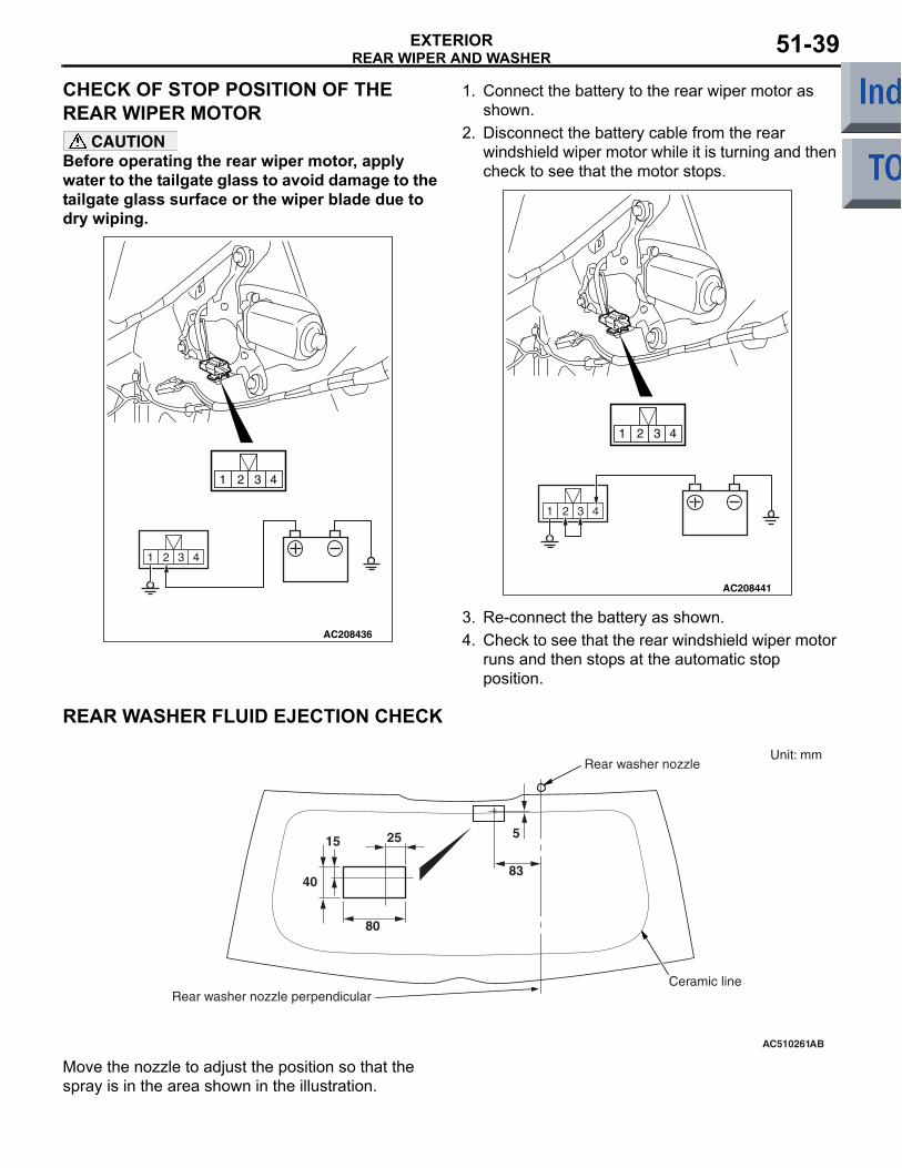
REAR WIPER AND WASHEREXTERIOR 51-39
CHECK OF STOP POSITION OF THE REAR WIPER MOTOR
CAUTIONBefore operating the rear wiper motor, apply water to the tailgate glass to avoid damage to the tailgate glass surface or the wiper blade due to dry wiping.
AC208436
1 2 3 4
1 2 3 4
1. Connect the battery to the rear wiper motor as shown.
2. Disconnect the battery cable from the rear windshield wiper motor while it is turning and then check to see that the motor stops.
AC208441
1 2 3 4
1 2 3 4
3. Re-connect the battery as shown.4. Check to see that the rear windshield wiper motor
runs and then stops at the automatic stop position.
REAR WASHER FLUID EJECTION CHECK
AC510261AB
Unit: mm
40
80
2515
83
5
Ceramic line
Rear washer nozzle
Rear washer nozzle perpendicular
Move the nozzle to adjust the position so that the spray is in the area shown in the illustration.

MARKEXTERIOR51-40
MARKREMOVAL AND INSTALLATION
M1511011801833
AC600667AB
1
4
5
N
N
2 6
3
1. Front three-diamond mark (Refer to P.51-2)
2. RALLIART icon mark <RALLIART> (Refer to P.51-2)
>>A<< 3. Front step plate <RALLIART>>>A<< 4. Rear three-diamond mark>>A<< 5. COLT mark>>A<< 6. RALLIART mark <RALLIART>
INSTALLATION SERVICE POINT>>A<<MARK APPLICATION1. Installation position
Attach each mark to the position shown in the illustration.
AC403306
A
A
285 mm
20 mm
AH
Scuff plate
Front step plate
Section A - A
Front seat attaching nut
3. Front step plate <RALLIART>

MARKEXTERIOR 51-41
AC403267
106 mm
AB
Centre line of vehicle
Tailgate outer panel press line
Rear three-diamond mark
4. Rear three-diamond mark
AC206522
9 mm
36 mm
AF
Tailgate outer panel end
Tailgate outer panel press line
Combination lamp end
5. COLT mark
AC403269AC
12 mm
50 mmRALLIART mark
Tailgate outer panel end
Tailgate outer panel press line
6. RALLIART mark <RALLIART>
2. Installation procedure(1) Use 3M ATD part number 8906 or equivalent
to clean the mark installation surfaces on the body.
CAUTIONWhen attaching the marks, the ambient tempera-ture should be 20 − 38°C and the air should be completely free of dust. If the ambient tempera-ture is lower than 20°C, the marks and the places on the vehicle body where the marks are to be attached should be heated to 20 − 30°C.
(2) Peel off the protection sheet on the back of the marks to paste it on the installation position.

DOOR MIRROREXTERIOR51-42
DOOR MIRRORTROUBLESHOOTING
M1511020000412The door mirror are controlled by the Smart Wiring System (SWS). For troubleshooting, refer to GROUP 54B, troubleshooting P.54B-35 or GROUP 54C, Troubleshooting P.54C-29.
DOOR MIRROR
REMOVAL AND INSTALLATIONM1511006400654
AC403307
1
2
AD
5
4
3
4.9 ± 0.7 N·m
2
4
A
A
Section A – AClaw
Remote controlled mirror switch removal steps
• Instrument panel under cover (Refer to group 52A, Instrument panel assembly P.52A-3).
1. Remote controlled mirror switch
Door mirror assembly removal steps
2. Door mirror base cover3. Door mirror assembly4. Door mirror
<<A>> 5. Mirror

DOOR MIRROREXTERIOR 51-43
REMOVAL SERVICE POINT<<A>> MIRROR REMOVAL
CAUTIONThe tab of the mirror is prone to breakage when working in cold temperature. Always use a hair drier or the like to warm up the mirror tab and its periphery to 20°C or higher prior to work. When the mirror is heated too quickly from its cold state, it may be broken.
AC207500
AA
AD
Section A – A
Claw positions
Claws
ClawClaw
Pivot plate
Recesses
Mirror
Mirror
Flat-tipped screwdriver
Flat-tipped screwdriver
Flat-tipped screwdriver
Slant the mirror upward with your hands. Then insert flat-tipped screwdriver wrapped with protective tape between the pivot plate and mirror through the cut-out from behind the mirror. Now pry off the mirror tab and release the lower side of the mirror as shown in the illustration.
INSPECTIONM1511019101548
DOOR MIRROR ASSEMBLY OPERATION CHECKRemove the door trim, and then connect the battery to the door mirror assembly connector to check that the door mirror operates.
AC313903
1 2 3 4 5 6 7
AB
Return
Retract
Forward-folding
Battery connection Direction operation
• Connect terminal 3 to the negative battery terminal.
• Connect terminal 5 to the positive battery terminal.
Up
• Connect terminal 3 to the positive battery terminal.
• Connect terminal 5 to the negative battery terminal.
Down
• Connect terminal 3 to the negative battery terminal.
• Connect terminal 4 to the positive battery terminal.
Right
• Connect terminal 3 to the positive battery terminal.
• Connect terminal 4 to the negative battery terminal.
Left
• Connect terminal 6 to the positive battery terminal.
• Connect terminal 7 to the negative battery terminal.
Retract
• Connect terminal 6 to the negative battery terminal.
• Connect terminal 7 to the positive battery terminal.
Return

DOOR MIRROREXTERIOR51-44
DOOR MIRROR CONTROL SWITCH CON-TINUITY CHECK
AC208667
1 25 6 7 8 9 10 11
3 4
Switch position Tester connection
Specified condition
OFF 1 − 2, 1 − 3, 1 − 4, 1 − 6, 1 − 10, 1 − 11, 2 − 9, 3 − 9, 6 − 9, 9 − 10, 9 − 11
Open circuit
Left side OFF 1 − 6, 1 − 10, 1 − 11, 6 − 9, 9 − 10, 9 − 11
Open circuit
Up 1 − 6, 9 − 11 Continuity (Less than 2Ω)
Down 1 − 11, 6 − 9Right 1 − 6, 9 − 10Left 1 − 10, 6 − 9
Right side
OFF 1 − 2, 1 − 3, 1 − 6, 2 − 9, 3 − 9, 6 − 9
Open circuit
Up 1 − 6, 3 − 9 Continuity (Less than 2Ω)
Down 1 − 3, 6 − 9Right 1 − 6, 2 − 9Left 1 − 2, 6 − 9
Retract and return 1 − 4 Continuity (Less than 2Ω)


![· Travelator design 51] TRAVELATOR SERIES 51] TRAVELATOR SERIES Exterior design Handrail design:Common type/slim type, vertical 1 Omm tempered glass](https://img.dokumen.tips/doc/110x75/5b3f35cd7f8b9af6438bdd61/-travelator-design-51-travelator-series-51-travelator-series-exterior-design.jpg)


