Embed Size (px)
Citation preview
EXTERIOR – FRONT BUMPER ET–1
ET
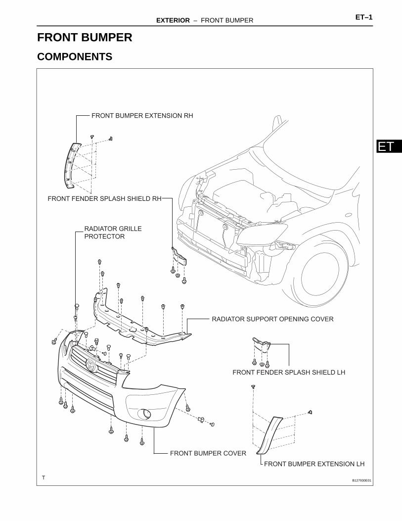
BODYEXTERIORFRONT BUMPERCOMPONENTS
FRONT BUMPER COVER
RADIATOR SUPPORT OPENING COVER
FRONT FENDER SPLASH SHIELD LH
FRONT FENDER SPLASH SHIELD RH
FRONT BUMPER EXTENSION LH
FRONT BUMPER EXTENSION RH
RADIATOR GRILLE
PROTECTOR
B127930E01
ET–2 EXTERIOR – FRONT BUMPER
ET
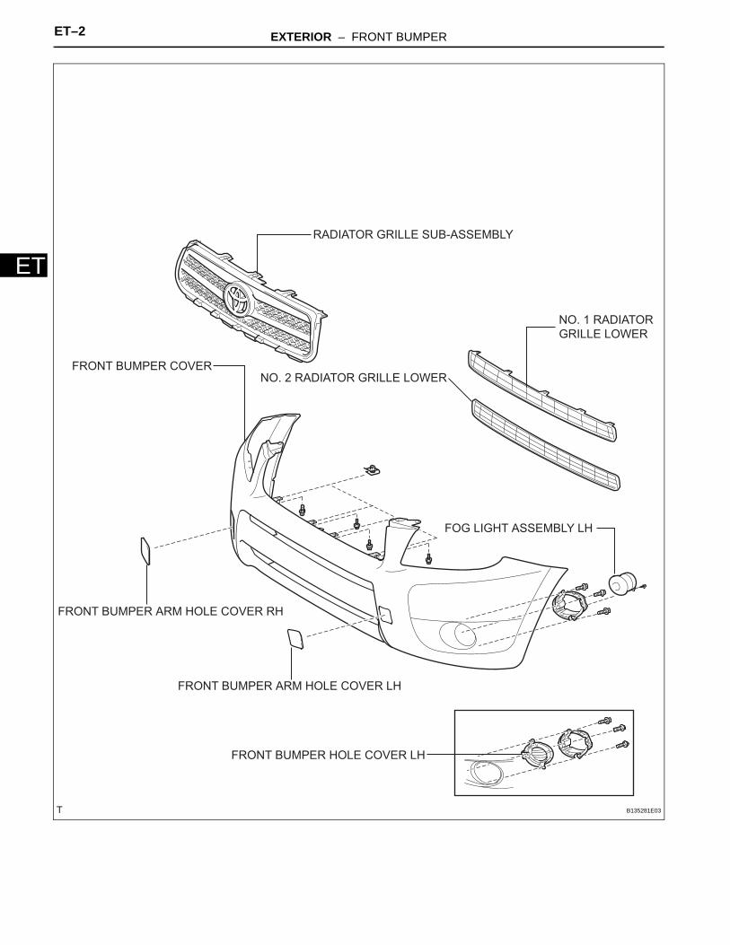
FOG LIGHT ASSEMBLY LH
FRONT BUMPER ARM HOLE COVER LH
FRONT BUMPER ARM HOLE COVER RH
FRONT BUMPER COVER
FRONT BUMPER HOLE COVER LH
RADIATOR GRILLE SUB-ASSEMBLY
NO. 1 RADIATOR
GRILLE LOWER
NO. 2 RADIATOR GRILLE LOWER
B135281E03
EXTERIOR – FRONT BUMPER ET–3
ET
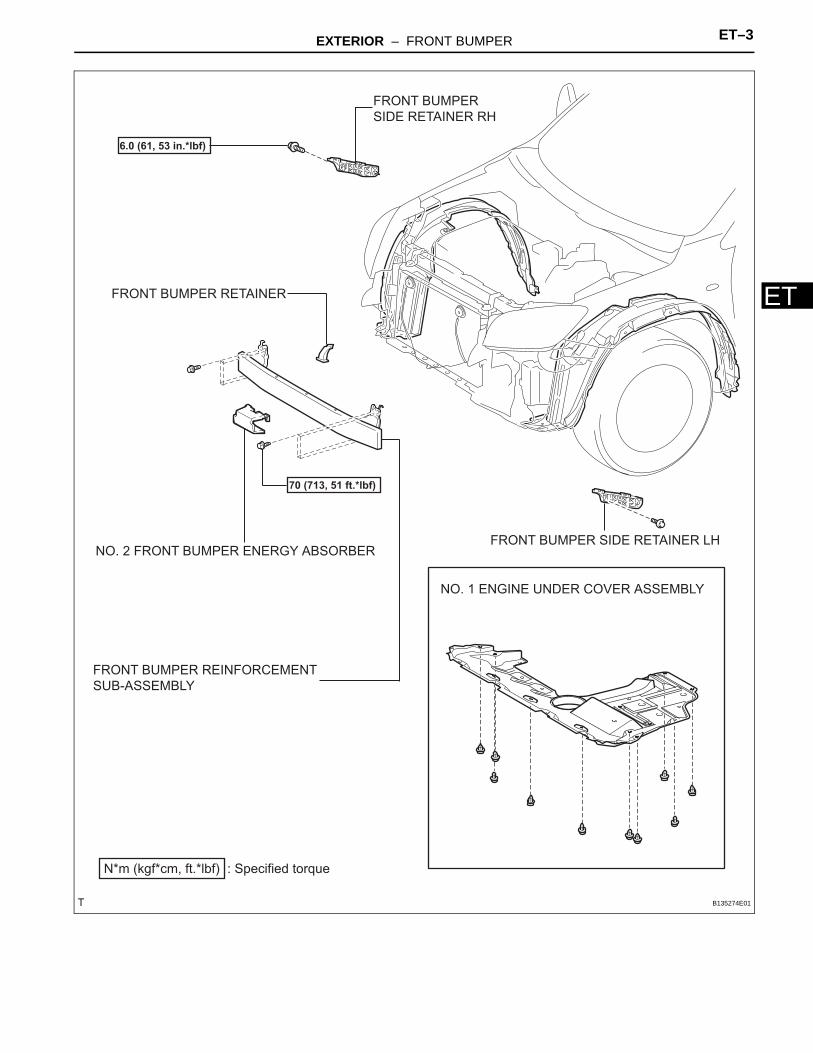
NO. 1 ENGINE UNDER COVER ASSEMBLY
FRONT BUMPER REINFORCEMENT
SUB-ASSEMBLY
FRONT BUMPER SIDE RETAINER LH
FRONT BUMPER
SIDE RETAINER RH
: Specified torqueN*m (kgf*cm, ft.*lbf)
70 (713, 51 ft.*lbf)
6.0 (61, 53 in.*lbf)
FRONT BUMPER RETAINER
NO. 2 FRONT BUMPER ENERGY ABSORBER
B135274E01
ET–4 EXTERIOR – FRONT BUMPER
ET
REMOVAL1. DISCONNECT CABLE FROM NEGATIVE BATTERY
TERMINALCAUTION:Wait at least 90 seconds after disconnecting the cable from the negative (-) battery terminal to prevent airbag and seat belt pretensioner activation.
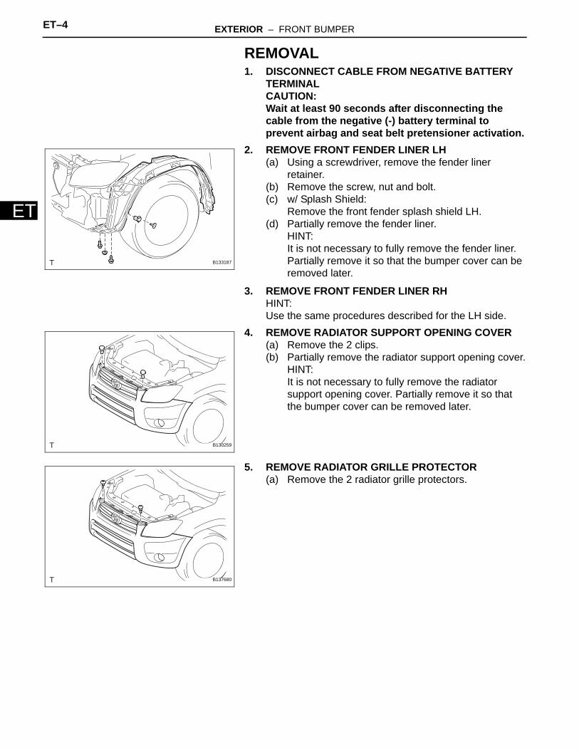
2. REMOVE FRONT FENDER LINER LH(a) Using a screwdriver, remove the fender liner
retainer.(b) Remove the screw, nut and bolt.(c) w/ Splash Shield:
Remove the front fender splash shield LH.(d) Partially remove the fender liner.
HINT:It is not necessary to fully remove the fender liner. Partially remove it so that the bumper cover can be removed later.
3. REMOVE FRONT FENDER LINER RHHINT:Use the same procedures described for the LH side.
4. REMOVE RADIATOR SUPPORT OPENING COVER(a) Remove the 2 clips.(b) Partially remove the radiator support opening cover.
HINT:It is not necessary to fully remove the radiator support opening cover. Partially remove it so that the bumper cover can be removed later.
5. REMOVE RADIATOR GRILLE PROTECTOR(a) Remove the 2 radiator grille protectors.
B133187
B130259
B137680
EXTERIOR – FRONT BUMPER ET–5
ET
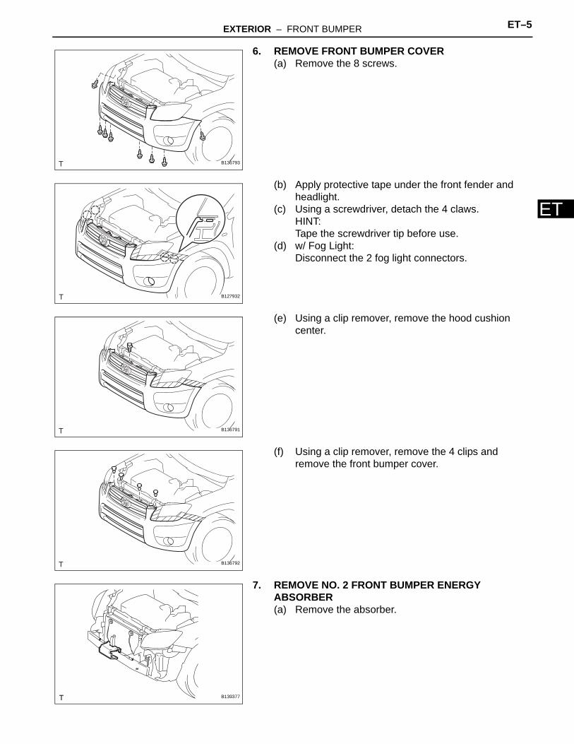
6. REMOVE FRONT BUMPER COVER(a) Remove the 8 screws.
(b) Apply protective tape under the front fender and headlight.
(c) Using a screwdriver, detach the 4 claws.HINT:Tape the screwdriver tip before use.
(d) w/ Fog Light:Disconnect the 2 fog light connectors.
(e) Using a clip remover, remove the hood cushion center.
(f) Using a clip remover, remove the 4 clips and remove the front bumper cover.
7. REMOVE NO. 2 FRONT BUMPER ENERGY ABSORBER(a) Remove the absorber.
B136793
B127932
B136791
B136792
B139377
ET–6 EXTERIOR – FRONT BUMPER
ET
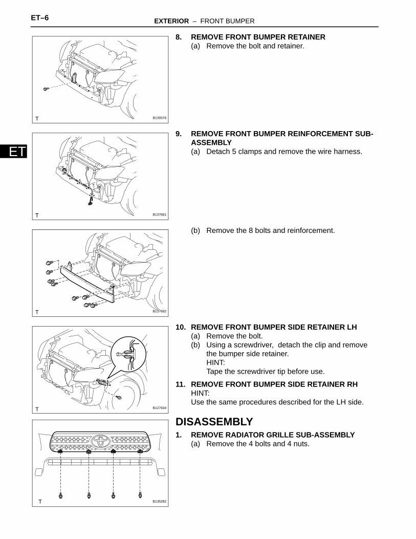
8. REMOVE FRONT BUMPER RETAINER(a) Remove the bolt and retainer.
9. REMOVE FRONT BUMPER REINFORCEMENT SUB-ASSEMBLY(a) Detach 5 clamps and remove the wire harness.
(b) Remove the 8 bolts and reinforcement.
10. REMOVE FRONT BUMPER SIDE RETAINER LH(a) Remove the bolt.(b) Using a screwdriver, detach the clip and remove
the bumper side retainer.HINT:Tape the screwdriver tip before use.
11. REMOVE FRONT BUMPER SIDE RETAINER RHHINT:Use the same procedures described for the LH side.
DISASSEMBLY1. REMOVE RADIATOR GRILLE SUB-ASSEMBLY
(a) Remove the 4 bolts and 4 nuts.
B139376
B137681
B137682
B127934
B135282
EXTERIOR – FRONT BUMPER ET–7
ET
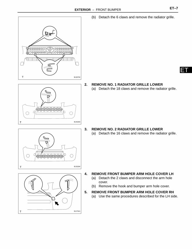
(b) Detach the 6 claws and remove the radiator grille.
2. REMOVE NO. 1 RADIATOR GRILLE LOWER(a) Detach the 18 claws and remove the radiator grille.
3. REMOVE NO. 2 RADIATOR GRILLE LOWER(a) Detach the 16 claws and remove the radiator grille.
4. REMOVE FRONT BUMPER ARM HOLE COVER LH(a) Detach the 2 claws and disconnect the arm hole
cover.(b) Remove the hook and bumper arm hole cover.
5. REMOVE FRONT BUMPER ARM HOLE COVER RH(a) Use the same procedures described for the LH side.
B136794
B135283
B135284
B127941
ET–8 EXTERIOR – FRONT BUMPER
ET
6. REMOVE FOG LIGHT ASSEMBLY LH(a) Remove the screw and fog light.(b) Remove the 3 bolts and fog light mounting bracket.
7. REMOVE FOG LIGHT ASSEMBLY RHHINT:Use the same procedures described for the LH side.
8. REMOVE FRONT BUMPER HOLE COVER LH (w/o Fog Light)(a) Remove the 3 bolts, bumper hole cover and fog light
mounting bracket.
9. REMOVE FRONT BUMPER HOLE COVER RH (w/o Fog Light)HINT:Use the same procedures described for the LH side.
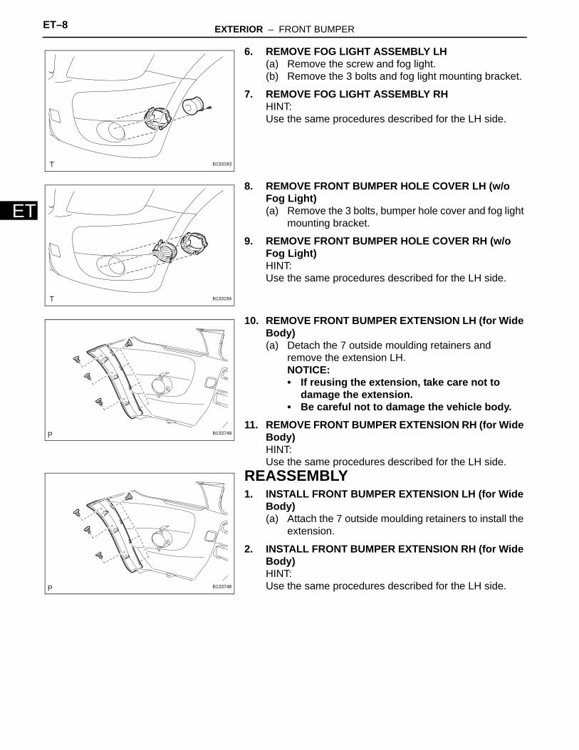
10. REMOVE FRONT BUMPER EXTENSION LH (for Wide Body)(a) Detach the 7 outside moulding retainers and
remove the extension LH.NOTICE:• If reusing the extension, take care not to
damage the extension.• Be careful not to damage the vehicle body.
11. REMOVE FRONT BUMPER EXTENSION RH (for Wide Body)HINT:Use the same procedures described for the LH side.
REASSEMBLY1. INSTALL FRONT BUMPER EXTENSION LH (for Wide
Body)(a) Attach the 7 outside moulding retainers to install the
extension.
2. INSTALL FRONT BUMPER EXTENSION RH (for Wide Body)HINT:Use the same procedures described for the LH side.
B133193
B133194
B133748
B133748
EXTERIOR – FRONT BUMPER ET–9
ET
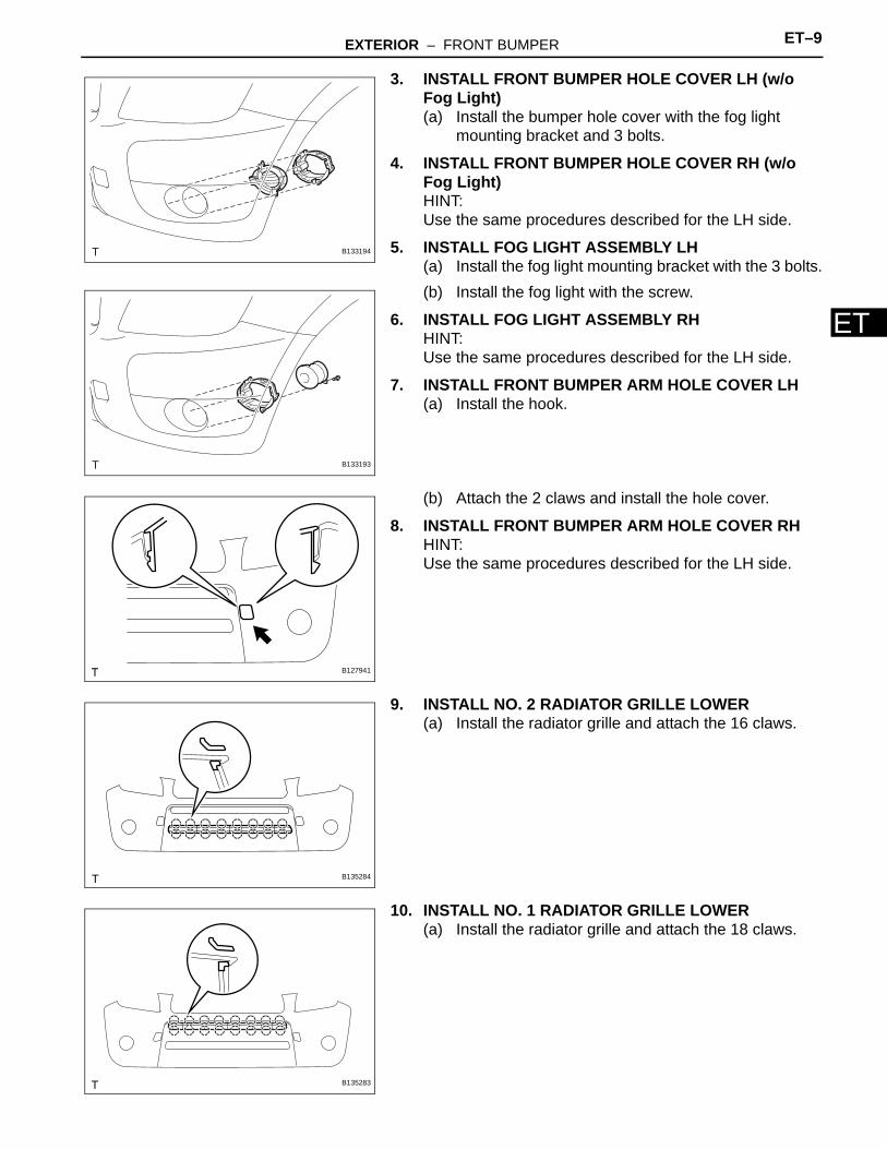
3. INSTALL FRONT BUMPER HOLE COVER LH (w/o Fog Light)(a) Install the bumper hole cover with the fog light
mounting bracket and 3 bolts.
4. INSTALL FRONT BUMPER HOLE COVER RH (w/o Fog Light)HINT:Use the same procedures described for the LH side.
5. INSTALL FOG LIGHT ASSEMBLY LH(a) Install the fog light mounting bracket with the 3 bolts.(b) Install the fog light with the screw.
6. INSTALL FOG LIGHT ASSEMBLY RHHINT:Use the same procedures described for the LH side.
7. INSTALL FRONT BUMPER ARM HOLE COVER LH(a) Install the hook.
(b) Attach the 2 claws and install the hole cover.
8. INSTALL FRONT BUMPER ARM HOLE COVER RHHINT:Use the same procedures described for the LH side.
9. INSTALL NO. 2 RADIATOR GRILLE LOWER(a) Install the radiator grille and attach the 16 claws.
10. INSTALL NO. 1 RADIATOR GRILLE LOWER(a) Install the radiator grille and attach the 18 claws.
B133194
B133193
B127941
B135284
B135283
ET–10 EXTERIOR – FRONT BUMPER
ET
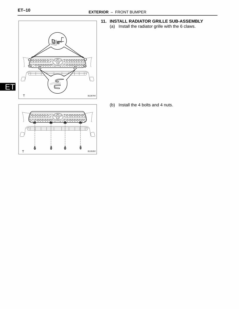
11. INSTALL RADIATOR GRILLE SUB-ASSEMBLY(a) Install the radiator grille with the 6 claws.
(b) Install the 4 bolts and 4 nuts.
B136794
B135282
EXTERIOR – FRONT BUMPER ET–11
ET
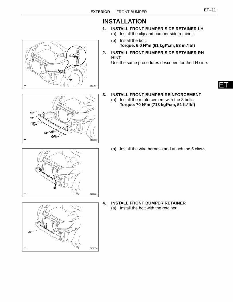
INSTALLATION1. INSTALL FRONT BUMPER SIDE RETAINER LH
(a) Install the clip and bumper side retainer.(b) Install the bolt.
Torque: 6.0 N*m (61 kgf*cm, 53 in.*lbf)2. INSTALL FRONT BUMPER SIDE RETAINER RH
HINT:Use the same procedures described for the LH side.
3. INSTALL FRONT BUMPER REINFORCEMENT(a) Install the reinforcement with the 8 bolts.
Torque: 70 N*m (713 kgf*cm, 51 ft.*lbf)
(b) Install the wire harness and attach the 5 claws.
4. INSTALL FRONT BUMPER RETAINER(a) Install the bolt with the retainer.
B127934
B137682
B137681
B139376
ET–12 EXTERIOR – FRONT BUMPER
ET
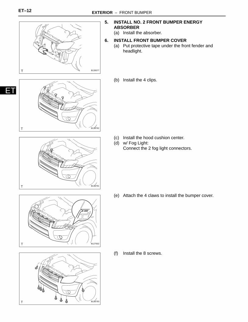
5. INSTALL NO. 2 FRONT BUMPER ENERGY ABSORBER(a) Install the absorber.
6. INSTALL FRONT BUMPER COVER(a) Put protective tape under the front fender and
headlight.
(b) Install the 4 clips.
(c) Install the hood cushion center.(d) w/ Fog Light:
Connect the 2 fog light connectors.
(e) Attach the 4 claws to install the bumper cover.
(f) Install the 8 screws.
B139377
B136792
B136791
B127932
B136793
EXTERIOR – FRONT BUMPER ET–13
ET
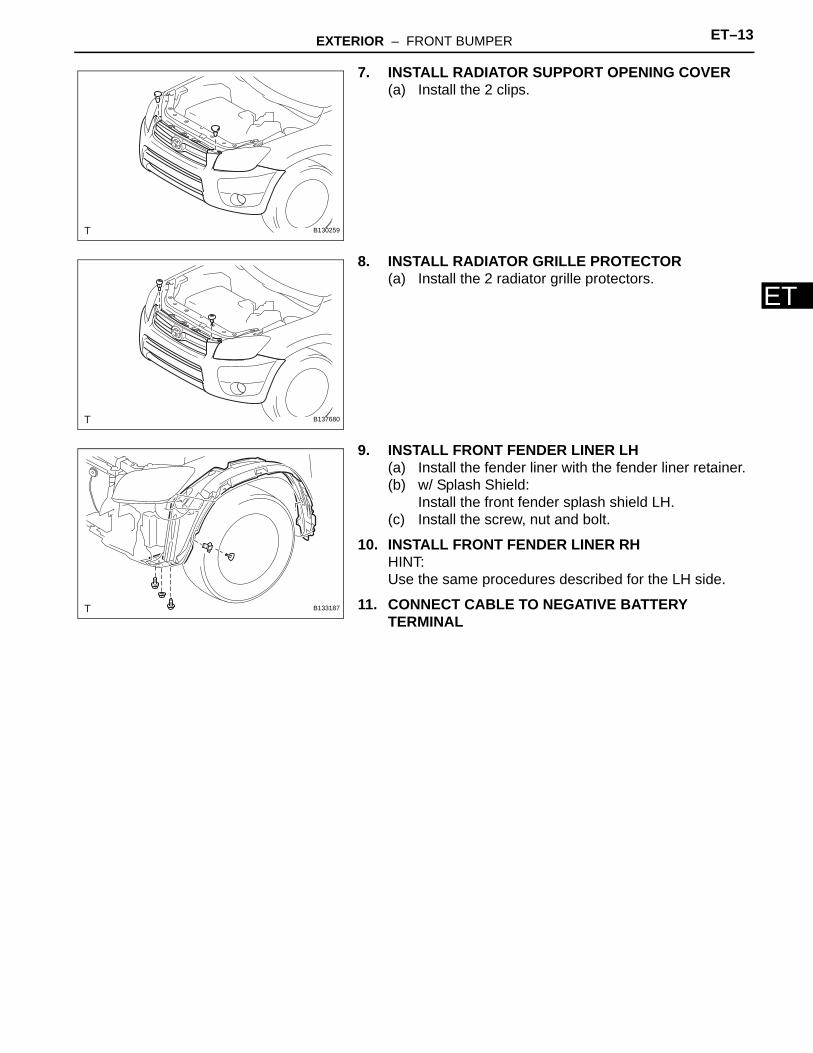
7. INSTALL RADIATOR SUPPORT OPENING COVER(a) Install the 2 clips.
8. INSTALL RADIATOR GRILLE PROTECTOR(a) Install the 2 radiator grille protectors.
9. INSTALL FRONT FENDER LINER LH(a) Install the fender liner with the fender liner retainer.(b) w/ Splash Shield:
Install the front fender splash shield LH.(c) Install the screw, nut and bolt.
10. INSTALL FRONT FENDER LINER RHHINT:Use the same procedures described for the LH side.
11. CONNECT CABLE TO NEGATIVE BATTERY TERMINAL
B130259
B137680
B133187
EXTERIOR – REAR BUMPER ET–13
ET
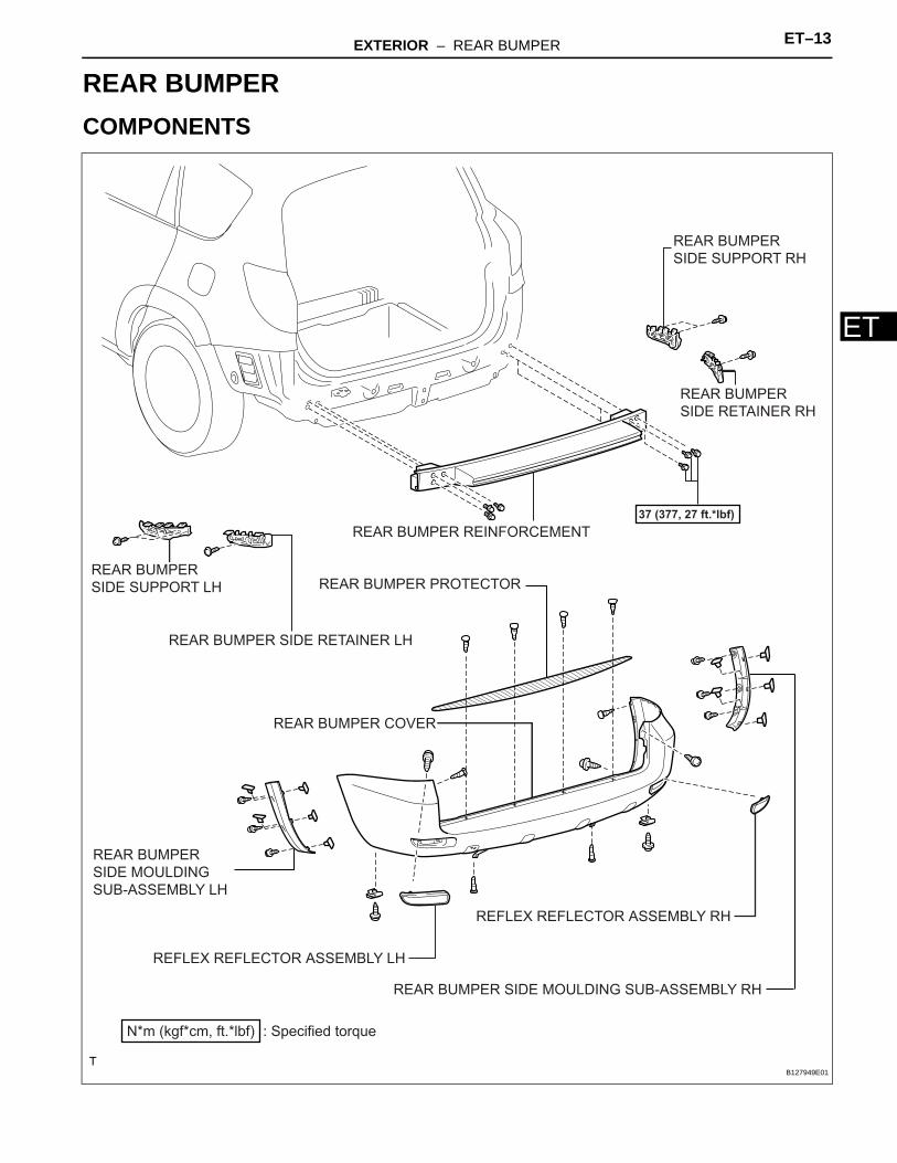
BODYEXTERIORREAR BUMPERCOMPONENTS
REAR BUMPER COVER
REAR BUMPER PROTECTOR
REAR BUMPER REINFORCEMENT
REAR BUMPER SIDE RETAINER LH
REAR BUMPER
SIDE RETAINER RH
REAR BUMPER
SIDE SUPPORT LH
REAR BUMPER
SIDE SUPPORT RH
REFLEX REFLECTOR ASSEMBLY LH
REFLEX REFLECTOR ASSEMBLY RH
: Specified torqueN*m (kgf*cm, ft.*lbf)
37 (377, 27 ft.*lbf)
REAR BUMPER
SIDE MOULDING
SUB-ASSEMBLY LH
REAR BUMPER SIDE MOULDING SUB-ASSEMBLY RH
B127949E01
ET–14 EXTERIOR – REAR BUMPER
ET
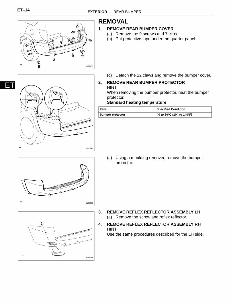
REMOVAL1. REMOVE REAR BUMPER COVER
(a) Remove the 9 screws and 7 clips.(b) Put protective tape under the quarter panel.
(c) Detach the 12 claws and remove the bumper cover.
2. REMOVE REAR BUMPER PROTECTORHINT:When removing the bumper protector, heat the bumper protector.Standard heating temperature
(a) Using a moulding remover, remove the bumper protector.
3. REMOVE REFLEX REFLECTOR ASSEMBLY LH(a) Remove the screw and reflex reflector.
4. REMOVE REFLEX REFLECTOR ASSEMBLY RHHINT:Use the same procedures described for the LH side.
B127951
B135275
Item Specified Condition
bumper protector 40 to 60°C (104 to 140°F)
B136795
B135278
EXTERIOR – REAR BUMPER ET–15
ET
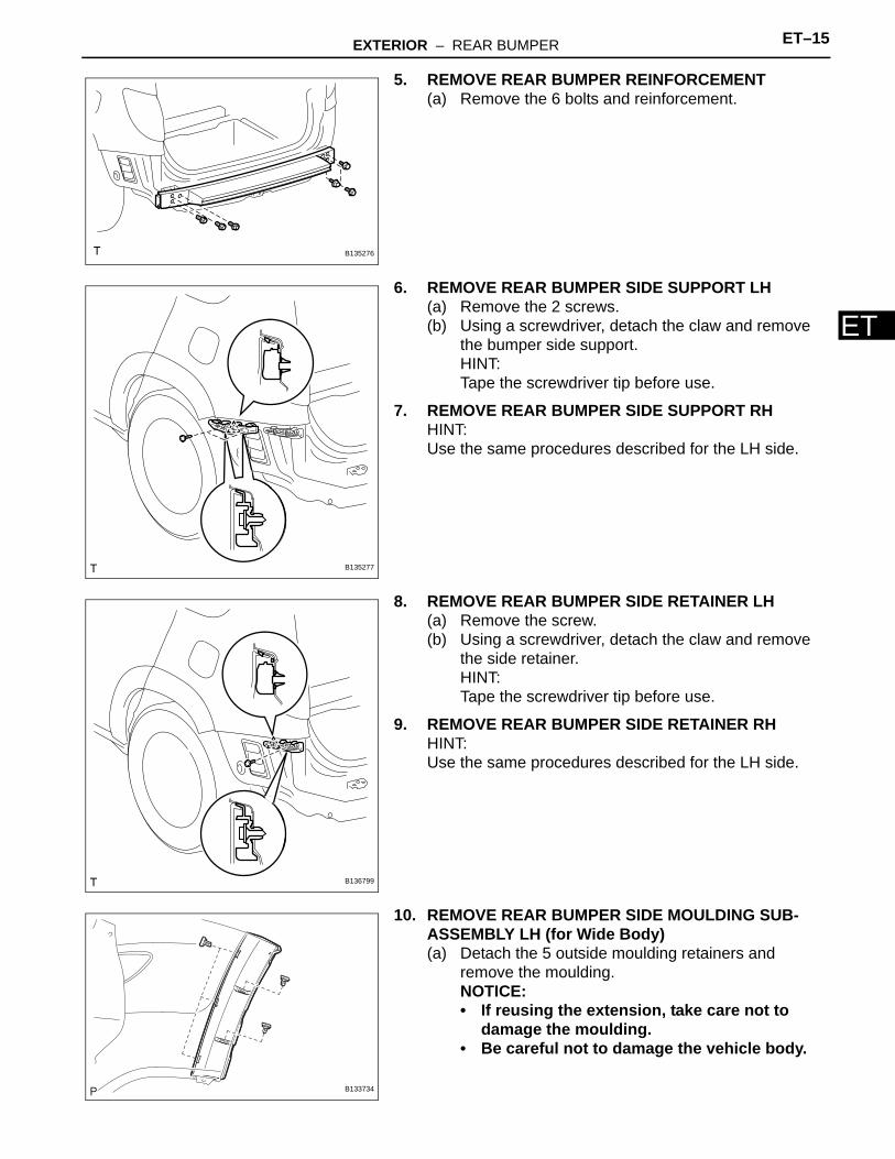
5. REMOVE REAR BUMPER REINFORCEMENT(a) Remove the 6 bolts and reinforcement.
6. REMOVE REAR BUMPER SIDE SUPPORT LH(a) Remove the 2 screws.(b) Using a screwdriver, detach the claw and remove
the bumper side support.HINT:Tape the screwdriver tip before use.
7. REMOVE REAR BUMPER SIDE SUPPORT RHHINT:Use the same procedures described for the LH side.
8. REMOVE REAR BUMPER SIDE RETAINER LH(a) Remove the screw.(b) Using a screwdriver, detach the claw and remove
the side retainer.HINT:Tape the screwdriver tip before use.
9. REMOVE REAR BUMPER SIDE RETAINER RHHINT:Use the same procedures described for the LH side.
10. REMOVE REAR BUMPER SIDE MOULDING SUB-ASSEMBLY LH (for Wide Body)(a) Detach the 5 outside moulding retainers and
remove the moulding.NOTICE:• If reusing the extension, take care not to
damage the moulding.• Be careful not to damage the vehicle body.
B135276
B135277
B136799
B133734
ET–16 EXTERIOR – REAR BUMPER
ET
11. REMOVE REAR BUMPER SIDE MOULDING SUB-ASSEMBLY RH (for Wide Body)HINT:Use the same procedures described for the LH side.
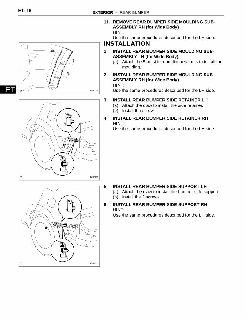
INSTALLATION1. INSTALL REAR BUMPER SIDE MOULDING SUB-
ASSEMBLY LH (for Wide Body)(a) Attach the 5 outside moulding retainers to install the
moulding.
2. INSTALL REAR BUMPER SIDE MOULDING SUB-ASSEMBLY RH (for Wide Body)HINT:Use the same procedures described for the LH side.
3. INSTALL REAR BUMPER SIDE RETAINER LH(a) Attach the claw to install the side retainer.(b) Install the screw.
4. INSTALL REAR BUMPER SIDE RETAINER RHHINT:Use the same procedures described for the LH side.
5. INSTALL REAR BUMPER SIDE SUPPORT LH(a) Attach the claw to install the bumper side support.(b) Install the 2 screws.
6. INSTALL REAR BUMPER SIDE SUPPORT RHHINT:Use the same procedures described for the LH side.
B133734
B136799
B135277
EXTERIOR – REAR BUMPER ET–17
ET
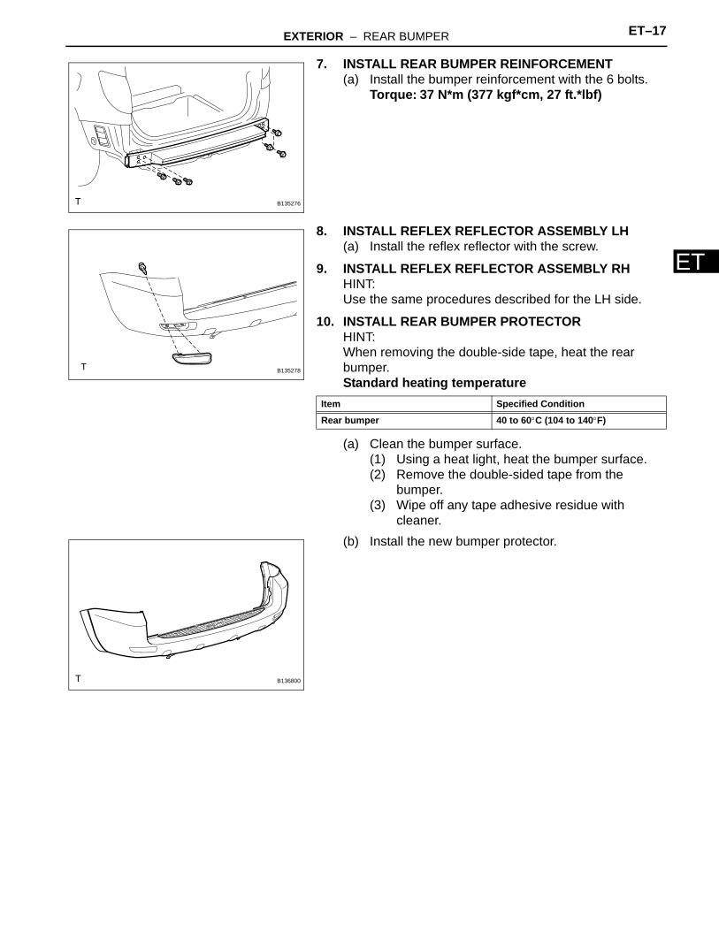
7. INSTALL REAR BUMPER REINFORCEMENT(a) Install the bumper reinforcement with the 6 bolts.
Torque: 37 N*m (377 kgf*cm, 27 ft.*lbf)
8. INSTALL REFLEX REFLECTOR ASSEMBLY LH(a) Install the reflex reflector with the screw.
9. INSTALL REFLEX REFLECTOR ASSEMBLY RHHINT:Use the same procedures described for the LH side.
10. INSTALL REAR BUMPER PROTECTORHINT:When removing the double-side tape, heat the rear bumper.Standard heating temperature
(a) Clean the bumper surface.(1) Using a heat light, heat the bumper surface.(2) Remove the double-sided tape from the
bumper.(3) Wipe off any tape adhesive residue with
cleaner.(b) Install the new bumper protector.
B135276
B135278
Item Specified Condition
Rear bumper 40 to 60°C (104 to 140°F)
B136800
ET–18 EXTERIOR – REAR BUMPER
ET
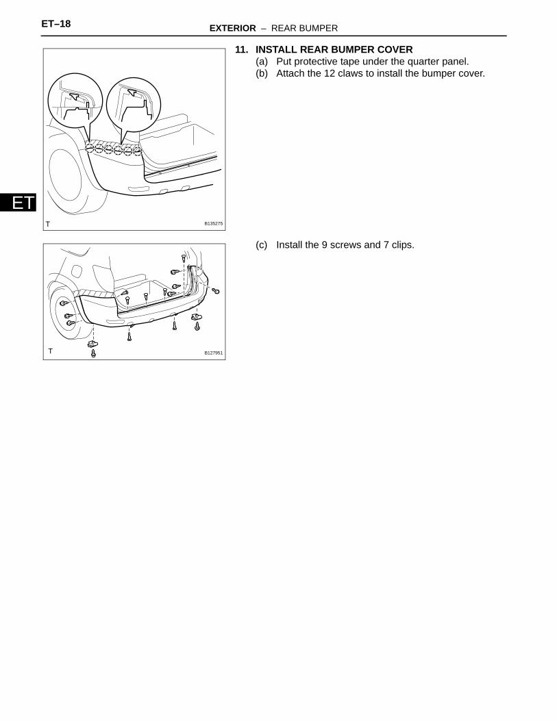
11. INSTALL REAR BUMPER COVER(a) Put protective tape under the quarter panel.(b) Attach the 12 claws to install the bumper cover.
(c) Install the 9 screws and 7 clips.
B135275
B127951
EXTERIOR – RADIATOR GRILLE ET–19
ET
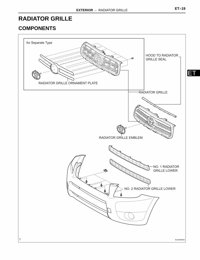
BODYEXTERIORRADIATOR GRILLECOMPONENTS
NO. 1 RADIATOR
GRILLE LOWER
NO. 2 RADIATOR GRILLE LOWER
RADIATOR GRILLE
RADIATOR GRILLE EMBLEM
RADIATOR GRILLE ORNAMENT PLATE
HOOD TO RADIATOR
GRILLE SEAL
for Separate Type
B135285E05
ET–20 EXTERIOR – RADIATOR GRILLE
ET
REMOVAL1. REMOVE RADIATOR GRILLE (See page ET-6)2. REMOVE NO. 1 RADIATOR GRILLE LOWER (See
page ET-7)3. REMOVE NO. 2 RADIATOR GRILLE LOWER (See
page ET-7)
EXTERIOR – RADIATOR GRILLE ET–21
ET
DISASSEMBLYHINT:When removing the ornament plate and emblem, heat the radiator grille, ornament plate and emblem using a heat light.Standard heating temperature
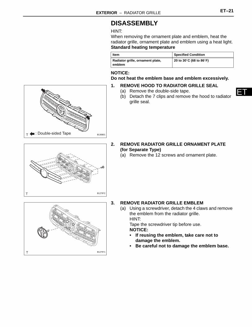
NOTICE:Do not heat the emblem base and emblem excessively.1. REMOVE HOOD TO RADIATOR GRILLE SEAL
(a) Remove the double-side tape.(b) Detach the 7 clips and remove the hood to radiator
grille seal.
2. REMOVE RADIATOR GRILLE ORNAMENT PLATE (for Separate Type)(a) Remove the 12 screws and ornament plate.
3. REMOVE RADIATOR GRILLE EMBLEM(a) Using a screwdriver, detach the 4 claws and remove
the emblem from the radiator grille.HINT:Tape the screwdriver tip before use.NOTICE:• If reusing the emblem, take care not to
damage the emblem.• Be careful not to damage the emblem base.
Item Specified Condition
Radiator grille, ornament plate, emblem
20 to 30°C (68 to 86°F)
: Double-sided Tape B136801
B127972
B127971
ET–22 EXTERIOR – RADIATOR GRILLE
ET
REASSEMBLYHINT:When installing the ornament plate and emblem, heat the radiator grille, ornament plate and emblem using a heat light.Standard heating temperature
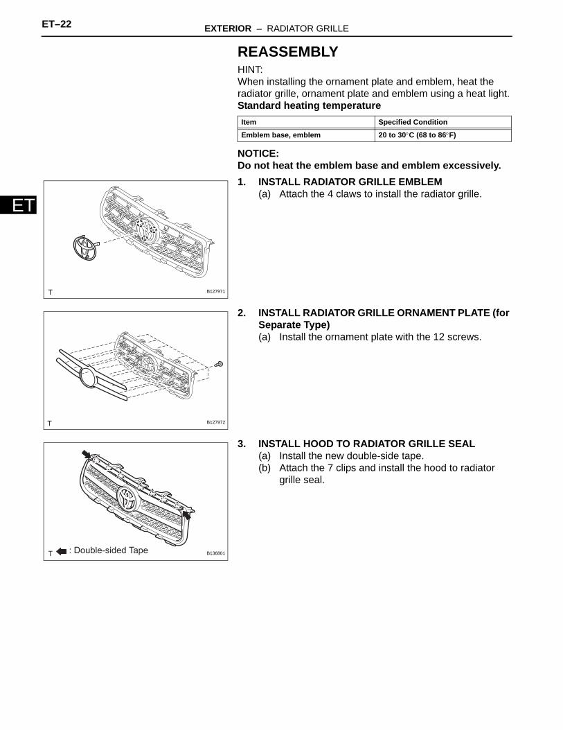
NOTICE:Do not heat the emblem base and emblem excessively.1. INSTALL RADIATOR GRILLE EMBLEM
(a) Attach the 4 claws to install the radiator grille.
2. INSTALL RADIATOR GRILLE ORNAMENT PLATE (for Separate Type)(a) Install the ornament plate with the 12 screws.
3. INSTALL HOOD TO RADIATOR GRILLE SEAL(a) Install the new double-side tape.(b) Attach the 7 clips and install the hood to radiator
grille seal.
Item Specified Condition
Emblem base, emblem 20 to 30°C (68 to 86°F)
B127971
B127972
: Double-sided Tape B136801
EXTERIOR – RADIATOR GRILLE ET–23
ET
INSTALLATION1. INSTALL NO. 2 RADIATOR GRILLE LOWER (See
page ET-9)2. INSTALL NO. 1 RADIATOR GRILLE LOWER (See
page ET-9)3. INSTALL RADIATOR GRILLE (See page ET-10)
ET–22 EXTERIOR – RADIATOR GRILLE (for 2GR-FE)
ET
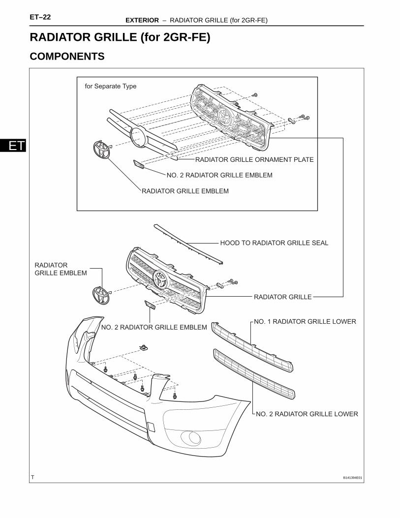
BODYEXTERIORRADIATOR GRILLE (for 2GR-FE)COMPONENTS
HOOD TO RADIATOR GRILLE SEAL
NO. 2 RADIATOR GRILLE EMBLEM
RADIATOR GRILLE EMBLEM
RADIATOR GRILLE ORNAMENT PLATE
NO. 1 RADIATOR GRILLE LOWER
NO. 2 RADIATOR GRILLE LOWER
RADIATOR GRILLE
for Separate Type
NO. 2 RADIATOR GRILLE EMBLEM
RADIATOR
GRILLE EMBLEM
B141394E01
EXTERIOR – RADIATOR GRILLE (for 2GR-FE) ET–23
ET
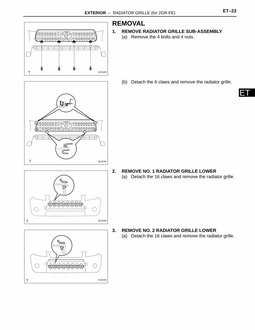
REMOVAL1. REMOVE RADIATOR GRILLE SUB-ASSEMBLY
(a) Remove the 4 bolts and 4 nuts.
(b) Detach the 6 claws and remove the radiator grille.
2. REMOVE NO. 1 RADIATOR GRILLE LOWER(a) Detach the 16 claws and remove the radiator grille.
3. REMOVE NO. 2 RADIATOR GRILLE LOWER(a) Detach the 16 claws and remove the radiator grille.
B135282
B136794
B135283
B135284
ET–24 EXTERIOR – RADIATOR GRILLE (for 2GR-FE)
ET
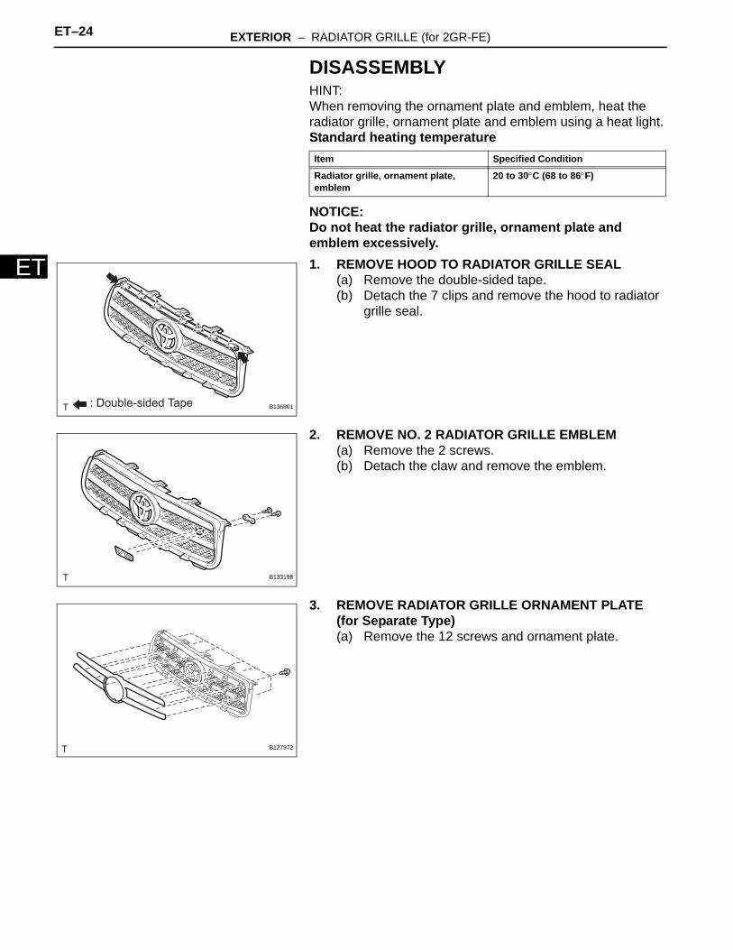
DISASSEMBLYHINT:When removing the ornament plate and emblem, heat the radiator grille, ornament plate and emblem using a heat light.Standard heating temperature
NOTICE:Do not heat the radiator grille, ornament plate and emblem excessively.1. REMOVE HOOD TO RADIATOR GRILLE SEAL
(a) Remove the double-sided tape.(b) Detach the 7 clips and remove the hood to radiator
grille seal.
2. REMOVE NO. 2 RADIATOR GRILLE EMBLEM(a) Remove the 2 screws.(b) Detach the claw and remove the emblem.
3. REMOVE RADIATOR GRILLE ORNAMENT PLATE (for Separate Type)(a) Remove the 12 screws and ornament plate.
Item Specified Condition
Radiator grille, ornament plate, emblem
20 to 30°C (68 to 86°F)
: Double-sided Tape B136801
B133198
B127972
EXTERIOR – RADIATOR GRILLE (for 2GR-FE) ET–25
ET
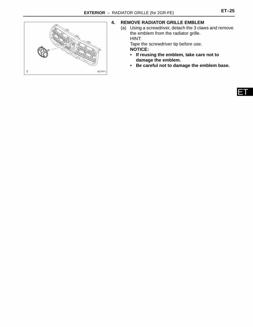
4. REMOVE RADIATOR GRILLE EMBLEM(a) Using a screwdriver, detach the 3 claws and remove
the emblem from the radiator grille.HINT:Tape the screwdriver tip before use.NOTICE:• If reusing the emblem, take care not to
damage the emblem.• Be careful not to damage the emblem base.
B127971
ET–26 EXTERIOR – RADIATOR GRILLE (for 2GR-FE)
ET
REASSEMBLYHINT:When installing the ornament plate and emblem, heat the radiator grille, ornament plate and emblem using a heat light.Standard heating temperature
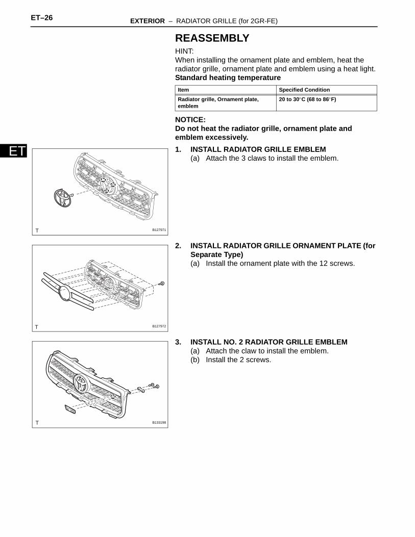
NOTICE:Do not heat the radiator grille, ornament plate and emblem excessively.1. INSTALL RADIATOR GRILLE EMBLEM
(a) Attach the 3 claws to install the emblem.
2. INSTALL RADIATOR GRILLE ORNAMENT PLATE (for Separate Type)(a) Install the ornament plate with the 12 screws.
3. INSTALL NO. 2 RADIATOR GRILLE EMBLEM(a) Attach the claw to install the emblem.(b) Install the 2 screws.
Item Specified Condition
Radiator grille, Ornament plate, emblem
20 to 30°C (68 to 86°F)
B127971
B127972
B133198
EXTERIOR – RADIATOR GRILLE (for 2GR-FE) ET–27
ET
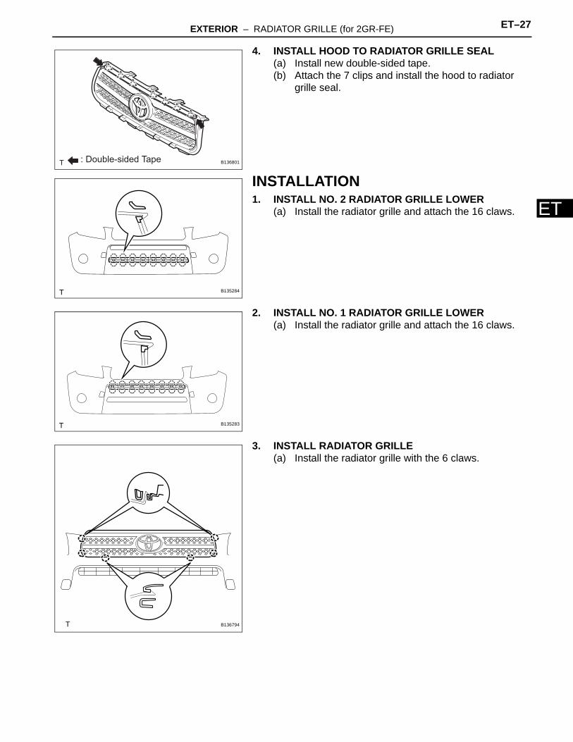
4. INSTALL HOOD TO RADIATOR GRILLE SEAL(a) Install new double-sided tape.(b) Attach the 7 clips and install the hood to radiator
grille seal.
INSTALLATION1. INSTALL NO. 2 RADIATOR GRILLE LOWER
(a) Install the radiator grille and attach the 16 claws.
2. INSTALL NO. 1 RADIATOR GRILLE LOWER(a) Install the radiator grille and attach the 16 claws.
3. INSTALL RADIATOR GRILLE(a) Install the radiator grille with the 6 claws.
: Double-sided Tape B136801
B135284
B135283
B136794
ET–28 EXTERIOR – RADIATOR GRILLE (for 2GR-FE)
ET
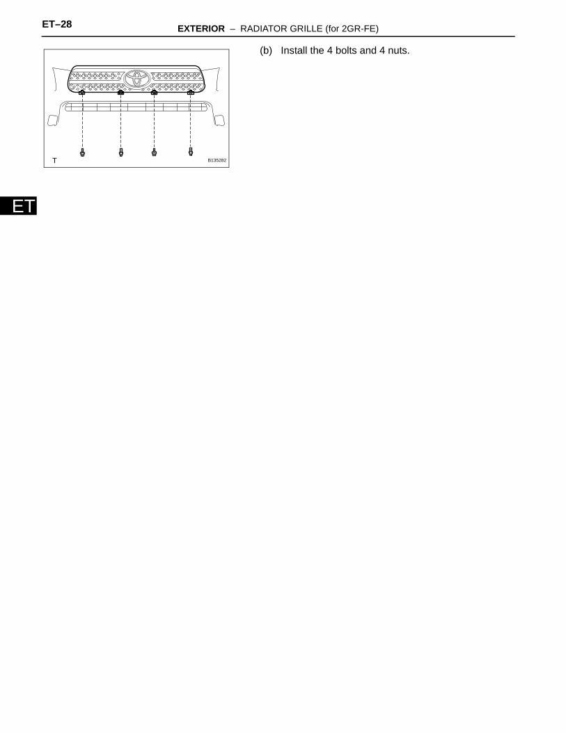
(b) Install the 4 bolts and 4 nuts.
B135282
EXTERIOR – NAME PLATE ET–27
ET
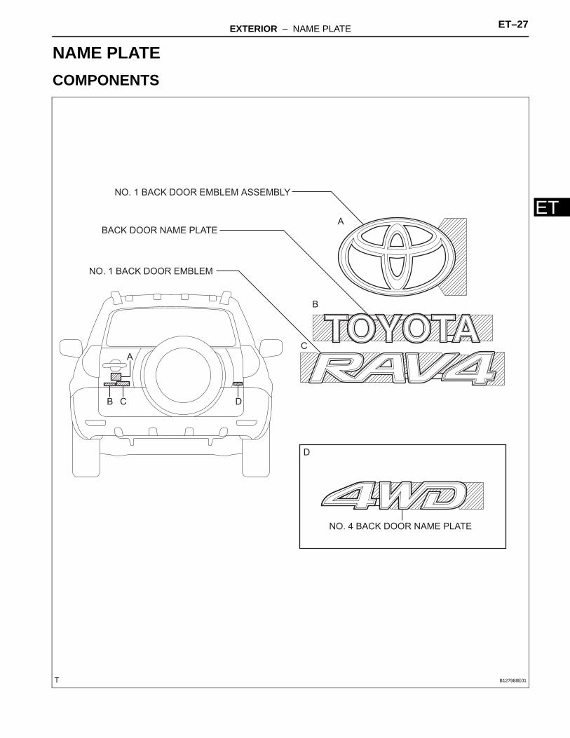
BODYEXTERIORNAME PLATECOMPONENTS
A
B
C
D
A
B C D
BACK DOOR NAME PLATE
NO. 4 BACK DOOR NAME PLATE
NO. 1 BACK DOOR EMBLEM
NO. 1 BACK DOOR EMBLEM ASSEMBLY
B127988E01
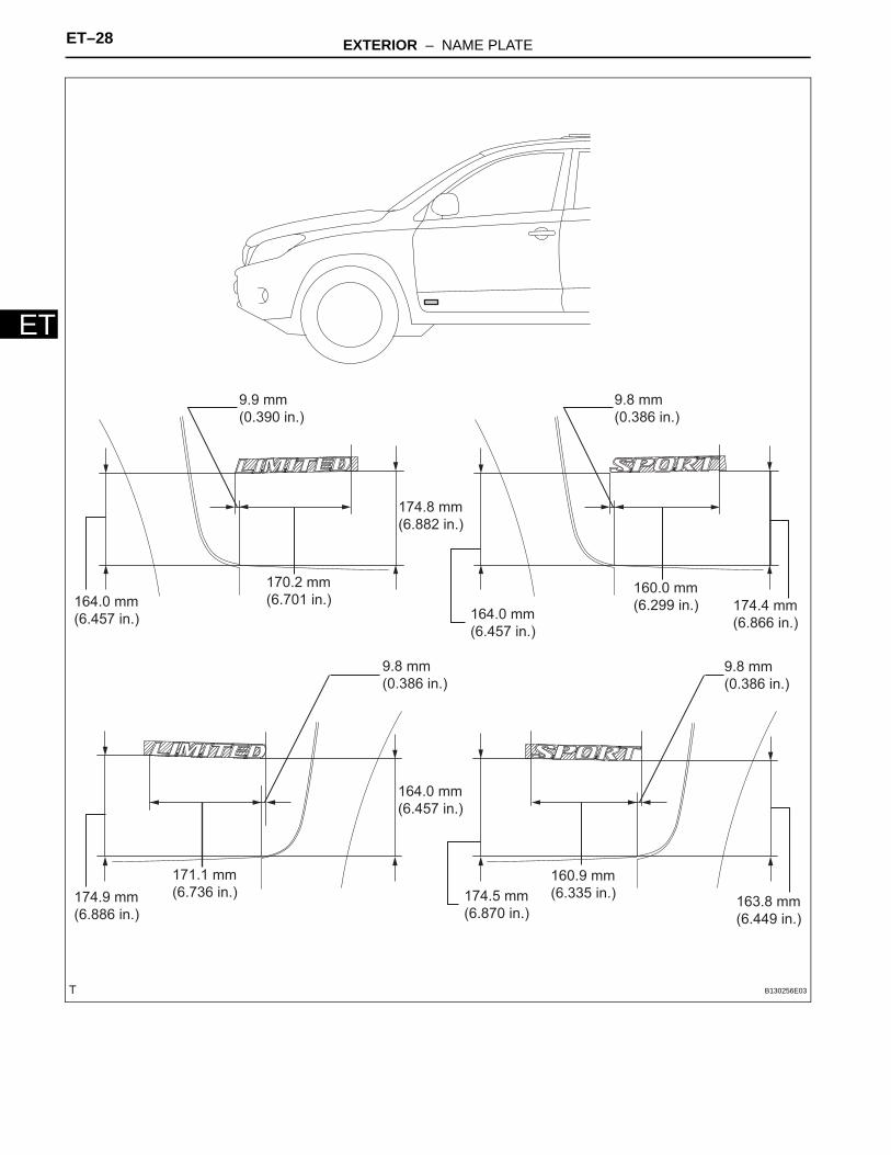
ET–28 EXTERIOR – NAME PLATE
ET
170.2 mm
(6.701 in.)164.0 mm
(6.457 in.) 164.0 mm
(6.457 in.)
164.0 mm
(6.457 in.)
174.8 mm
(6.882 in.)
9.9 mm
(0.390 in.)
9.8 mm
(0.386 in.)
9.8 mm
(0.386 in.)
160.0 mm
(6.299 in.) 174.4 mm
(6.866 in.)
174.9 mm
(6.886 in.)
171.1 mm
(6.736 in.) 174.5 mm
(6.870 in.)
160.9 mm
(6.335 in.)163.8 mm
(6.449 in.)
9.8 mm
(0.386 in.)
B130256E03
EXTERIOR – NAME PLATE ET–29
ET
REMOVALNOTICE:Do not heat the vehicle body, emblem and name plate excessively.HINT:When removing the emblem and name plate, heat the vehicle body, emblem and name plate using a heat light.Standard heating temperature
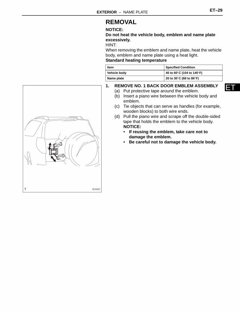
1. REMOVE NO. 1 BACK DOOR EMBLEM ASSEMBLY(a) Put protective tape around the emblem.(b) Insert a piano wire between the vehicle body and
emblem.(c) Tie objects that can serve as handles (for example,
wooden blocks) to both wire ends.(d) Pull the piano wire and scrape off the double-sided
tape that holds the emblem to the vehicle body.NOTICE:• If reusing the emblem, take care not to
damage the emblem.• Be careful not to damage the vehicle body.
Item Specified Condition
Vehicle body 40 to 60°C (104 to 140°F)
Name plate 20 to 30°C (68 to 86°F)
B131627
ET–30 EXTERIOR – NAME PLATE
ET
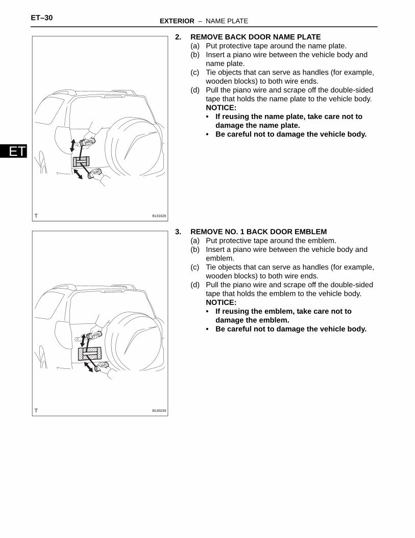
2. REMOVE BACK DOOR NAME PLATE(a) Put protective tape around the name plate.(b) Insert a piano wire between the vehicle body and
name plate.(c) Tie objects that can serve as handles (for example,
wooden blocks) to both wire ends.(d) Pull the piano wire and scrape off the double-sided
tape that holds the name plate to the vehicle body.NOTICE:• If reusing the name plate, take care not to
damage the name plate.• Be careful not to damage the vehicle body.
3. REMOVE NO. 1 BACK DOOR EMBLEM(a) Put protective tape around the emblem.(b) Insert a piano wire between the vehicle body and
emblem.(c) Tie objects that can serve as handles (for example,
wooden blocks) to both wire ends.(d) Pull the piano wire and scrape off the double-sided
tape that holds the emblem to the vehicle body.NOTICE:• If reusing the emblem, take care not to
damage the emblem.• Be careful not to damage the vehicle body.
B131628
B130239
EXTERIOR – NAME PLATE ET–31
ET
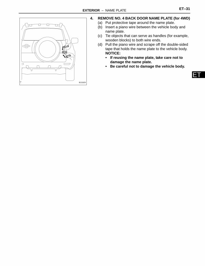
4. REMOVE NO. 4 BACK DOOR NAME PLATE (for 4WD)(a) Put protective tape around the name plate.(b) Insert a piano wire between the vehicle body and
name plate.(c) Tie objects that can serve as handles (for example,
wooden blocks) to both wire ends.(d) Pull the piano wire and scrape off the double-sided
tape that holds the name plate to the vehicle body.NOTICE:• If reusing the name plate, take care not to
damage the name plate.• Be careful not to damage the vehicle body.
B131629
ET–32 EXTERIOR – NAME PLATE
ET
INSTALLATIONNOTICE:Do not heat the vehicle body, emblem and name plate excessively.HINT:When installing the emblem and name plate, heat the vehicle body, emblem and name plate using a heat light.Standard heating temperature
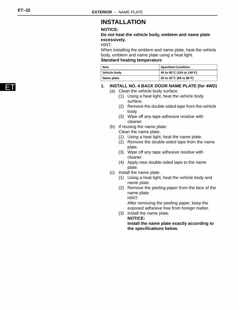
1. INSTALL NO. 4 BACK DOOR NAME PLATE (for 4WD)(a) Clean the vehicle body surface.
(1) Using a heat light, heat the vehicle body surface.
(2) Remove the double-sided tape from the vehicle body.
(3) Wipe off any tape adhesive residue with cleaner.
(b) If reusing the name plate:Clean the name plate.(1) Using a heat light, heat the name plate.(2) Remove the double-sided tape from the name
plate.(3) Wipe off any tape adhesive residue with
cleaner.(4) Apply new double-sided tape to the name
plate.(c) Install the name plate.
(1) Using a heat light, heat the vehicle body and name plate.
(2) Remove the peeling paper from the face of the name plate.HINT:After removing the peeling paper, keep the exposed adhesive free from foreign matter.
(3) Install the name plate.NOTICE:Install the name plate exactly according to the specifications below.
Item Specified Condition
Vehicle body 40 to 60°C (104 to 140°F)
Name plate 20 to 30°C (68 to 86°F)
EXTERIOR – NAME PLATE ET–33
ET
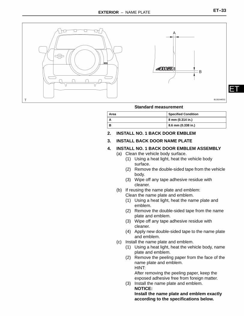
Standard measurement
2. INSTALL NO. 1 BACK DOOR EMBLEM3. INSTALL BACK DOOR NAME PLATE4. INSTALL NO. 1 BACK DOOR EMBLEM ASSEMBLY
(a) Clean the vehicle body surface.(1) Using a heat light, heat the vehicle body
surface.(2) Remove the double-sided tape from the vehicle
body.(3) Wipe off any tape adhesive residue with
cleaner.(b) If reusing the name plate and emblem:
Clean the name plate and emblem.(1) Using a heat light, heat the name plate and
emblem.(2) Remove the double-sided tape from the name
plate and emblem.(3) Wipe off any tape adhesive residue with
cleaner.(4) Apply new double-sided tape to the name plate
and emblem.(c) Install the name plate and emblem.
(1) Using a heat light, heat the vehicle body, name plate and emblem.
(2) Remove the peeling paper from the face of the name plate and emblem.HINT:After removing the peeling paper, keep the exposed adhesive free from foreign matter.
(3) Install the name plate and emblem.NOTICE:Install the name plate and emblem exactly according to the specifications below.
A
B
B130244E02
Area Specified Condition
A 8 mm (0.314 in.)
B 8.6 mm (0.338 in.)
ET–34 EXTERIOR – NAME PLATE
ET
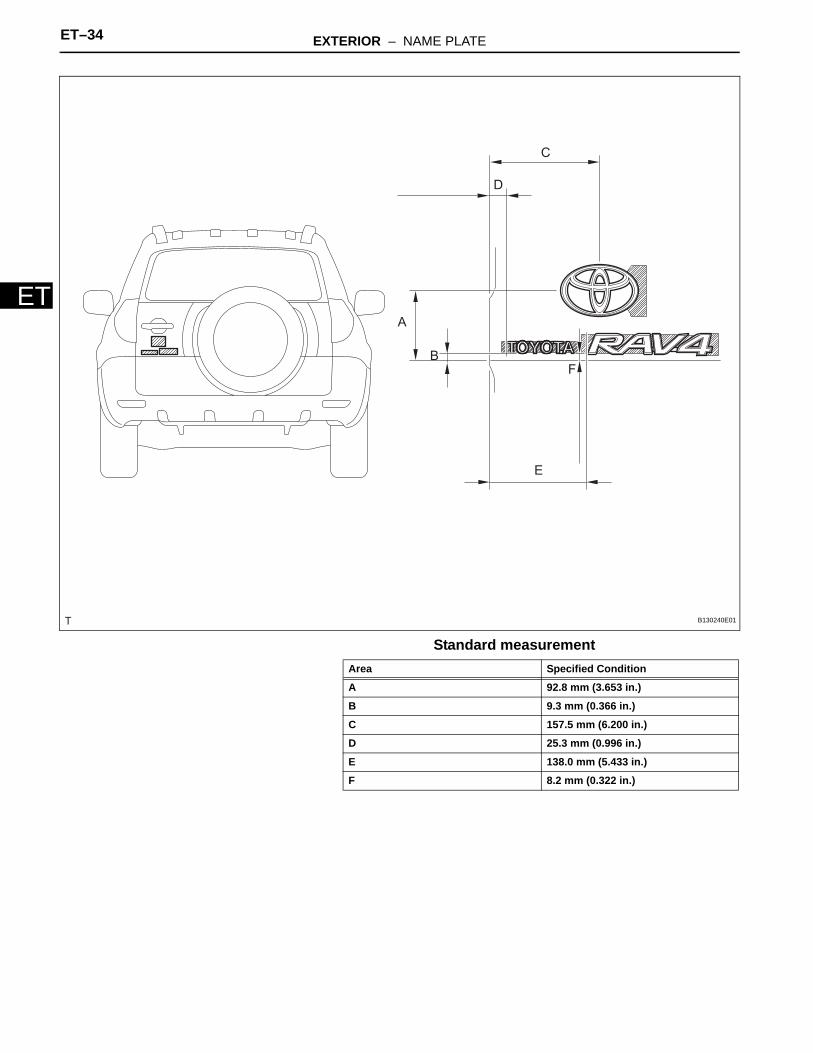
Standard measurement
A
B
C
D
E
F
B130240E01
Area Specified Condition
A 92.8 mm (3.653 in.)
B 9.3 mm (0.366 in.)
C 157.5 mm (6.200 in.)
D 25.3 mm (0.996 in.)
E 138.0 mm (5.433 in.)
F 8.2 mm (0.322 in.)
ET–34 EXTERIOR – REAR SPOILER
ET
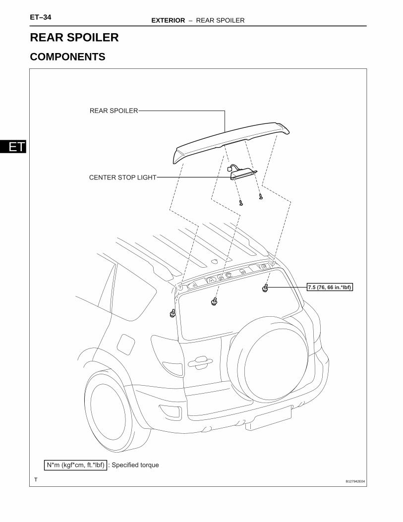
BODYEXTERIORREAR SPOILERCOMPONENTS
REAR SPOILER
: Specified torqueN*m (kgf*cm, ft.*lbf)
7.5 (76, 66 in.*lbf)
CENTER STOP LIGHT
B127942E04
EXTERIOR – REAR SPOILER ET–35
ET
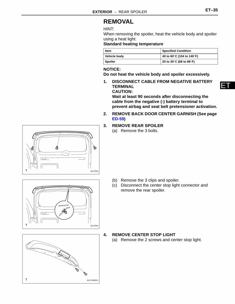
REMOVALHINT:When removing the spoiler, heat the vehicle body and spoiler using a heat light.Standard heating temperature
NOTICE:Do not heat the vehicle body and spoiler excessively.1. DISCONNECT CABLE FROM NEGATIVE BATTERY
TERMINALCAUTION:Wait at least 90 seconds after disconnecting the cable from the negative (-) battery terminal to prevent airbag and seat belt pretensioner activation.
2. REMOVE BACK DOOR CENTER GARNISH (See page ED-59)
3. REMOVE REAR SPOILER(a) Remove the 3 bolts.
(b) Remove the 3 clips and spoiler.(c) Disconnect the center stop light connector and
remove the rear spoiler.
4. REMOVE CENTER STOP LIGHT(a) Remove the 2 screws and center stop light.
Item Specified Condition
Vehicle body 40 to 60°C (104 to 140°F)
Spoiler 20 to 30°C (68 to 86°F)
B127943
B127944
B127945E01
ET–36 EXTERIOR – REAR SPOILER
ET
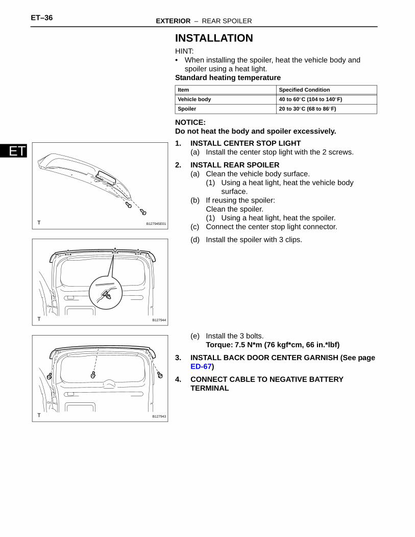
INSTALLATIONHINT:• When installing the spoiler, heat the vehicle body and
spoiler using a heat light.Standard heating temperature
NOTICE:Do not heat the body and spoiler excessively.1. INSTALL CENTER STOP LIGHT
(a) Install the center stop light with the 2 screws.
2. INSTALL REAR SPOILER(a) Clean the vehicle body surface.
(1) Using a heat light, heat the vehicle body surface.
(b) If reusing the spoiler:Clean the spoiler.(1) Using a heat light, heat the spoiler.
(c) Connect the center stop light connector.
(d) Install the spoiler with 3 clips.
(e) Install the 3 bolts.Torque: 7.5 N*m (76 kgf*cm, 66 in.*lbf)
3. INSTALL BACK DOOR CENTER GARNISH (See page ED-67)
4. CONNECT CABLE TO NEGATIVE BATTERY TERMINAL
Item Specified Condition
Vehicle body 40 to 60°C (104 to 140°F)
Spoiler 20 to 30°C (68 to 86°F)
B127945E01
B127944
B127943
EXTERIOR – ROOF RACK ET–37
ET
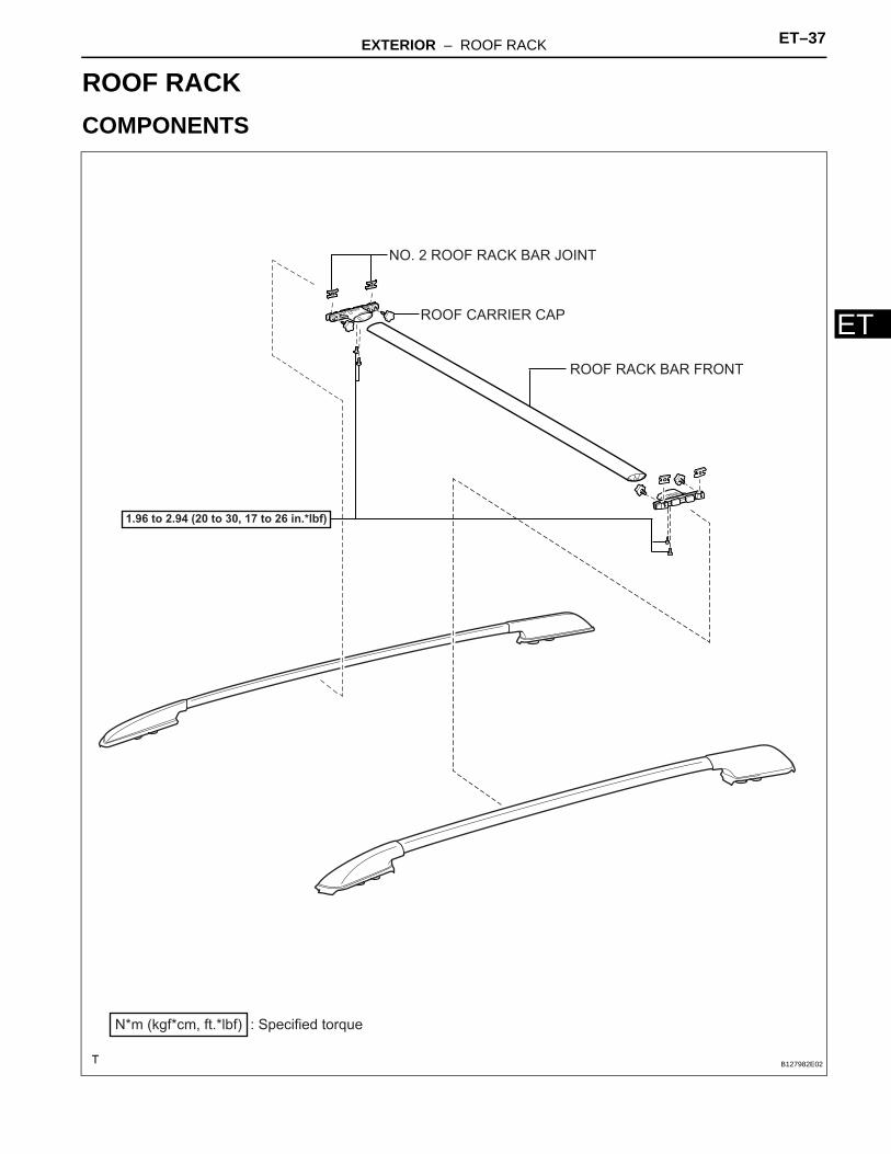
BODYEXTERIORROOF RACKCOMPONENTS
ROOF RACK BAR FRONT
NO. 2 ROOF RACK BAR JOINT
ROOF CARRIER CAP
: Specified torqueN*m (kgf*cm, ft.*lbf)
1.96 to 2.94 (20 to 30, 17 to 26 in.*lbf)
B127982E02
ET–38 EXTERIOR – ROOF RACK
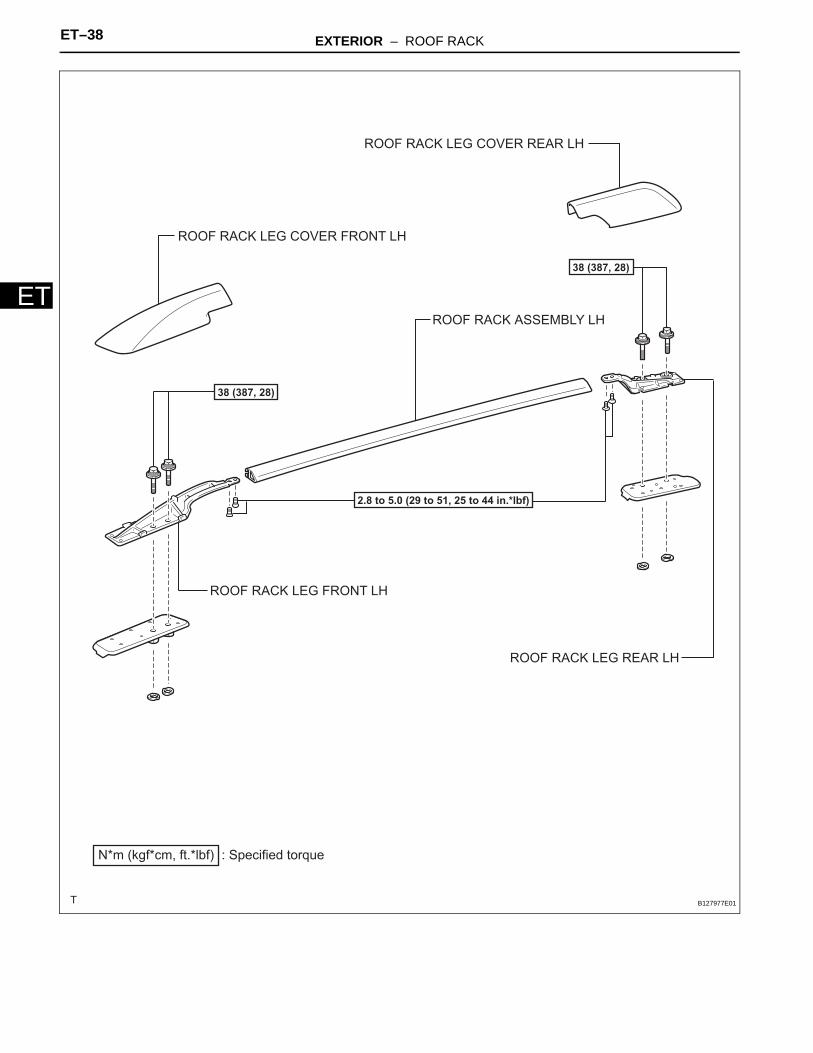
ETROOF RACK ASSEMBLY LH
ROOF RACK LEG COVER FRONT LH
ROOF RACK LEG COVER REAR LH
ROOF RACK LEG FRONT LH
ROOF RACK LEG REAR LH
: Specified torqueN*m (kgf*cm, ft.*lbf)
38 (387, 28)
38 (387, 28)
2.8 to 5.0 (29 to 51, 25 to 44 in.*lbf)
B127977E01
EXTERIOR – ROOF RACK ET–39
ET
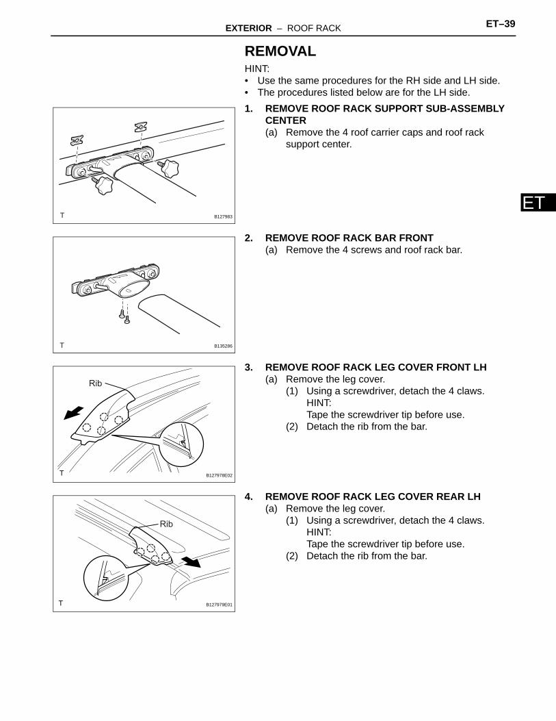
REMOVALHINT:• Use the same procedures for the RH side and LH side.• The procedures listed below are for the LH side.1. REMOVE ROOF RACK SUPPORT SUB-ASSEMBLY
CENTER(a) Remove the 4 roof carrier caps and roof rack
support center.
2. REMOVE ROOF RACK BAR FRONT(a) Remove the 4 screws and roof rack bar.
3. REMOVE ROOF RACK LEG COVER FRONT LH(a) Remove the leg cover.
(1) Using a screwdriver, detach the 4 claws.HINT:Tape the screwdriver tip before use.
(2) Detach the rib from the bar.
4. REMOVE ROOF RACK LEG COVER REAR LH(a) Remove the leg cover.
(1) Using a screwdriver, detach the 4 claws.HINT:Tape the screwdriver tip before use.
(2) Detach the rib from the bar.
B127983
B135286
Rib
B127978E02
Rib
B127979E01
ET–40 EXTERIOR – ROOF RACK
ET
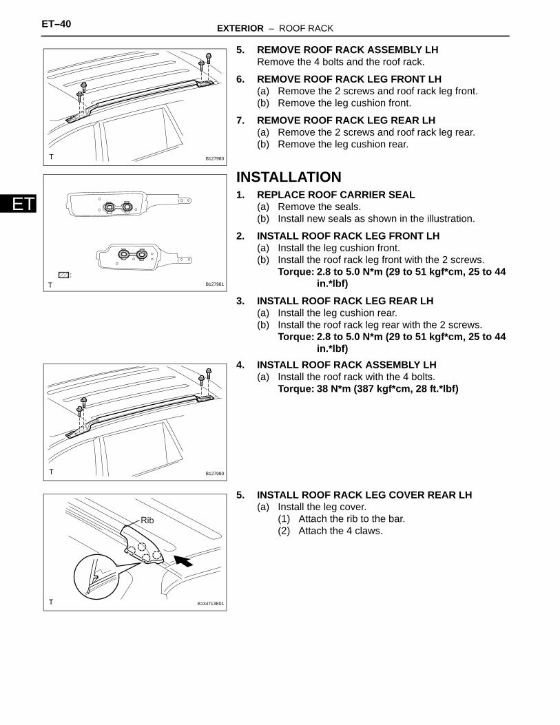
5. REMOVE ROOF RACK ASSEMBLY LHRemove the 4 bolts and the roof rack.
6. REMOVE ROOF RACK LEG FRONT LH(a) Remove the 2 screws and roof rack leg front.(b) Remove the leg cushion front.
7. REMOVE ROOF RACK LEG REAR LH(a) Remove the 2 screws and roof rack leg rear.(b) Remove the leg cushion rear.
INSTALLATION1. REPLACE ROOF CARRIER SEAL
(a) Remove the seals.(b) Install new seals as shown in the illustration.
2. INSTALL ROOF RACK LEG FRONT LH(a) Install the leg cushion front.(b) Install the roof rack leg front with the 2 screws.
Torque: 2.8 to 5.0 N*m (29 to 51 kgf*cm, 25 to 44 in.*lbf)
3. INSTALL ROOF RACK LEG REAR LH(a) Install the leg cushion rear.(b) Install the roof rack leg rear with the 2 screws.
Torque: 2.8 to 5.0 N*m (29 to 51 kgf*cm, 25 to 44 in.*lbf)
4. INSTALL ROOF RACK ASSEMBLY LH(a) Install the roof rack with the 4 bolts.
Torque: 38 N*m (387 kgf*cm, 28 ft.*lbf)
5. INSTALL ROOF RACK LEG COVER REAR LH(a) Install the leg cover.
(1) Attach the rib to the bar.(2) Attach the 4 claws.
B127980
B127981
B127980
Rib
B134713E01
EXTERIOR – ROOF RACK ET–41
ET
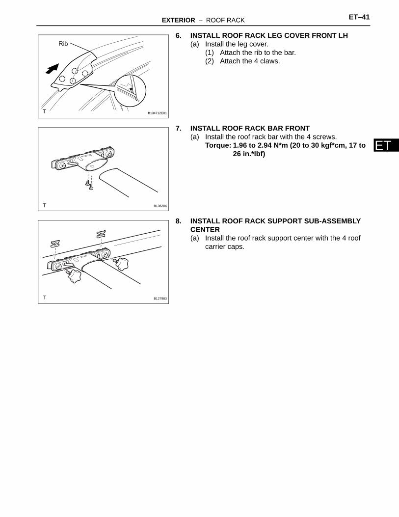
6. INSTALL ROOF RACK LEG COVER FRONT LH(a) Install the leg cover.
(1) Attach the rib to the bar.(2) Attach the 4 claws.
7. INSTALL ROOF RACK BAR FRONT(a) Install the roof rack bar with the 4 screws.
Torque: 1.96 to 2.94 N*m (20 to 30 kgf*cm, 17 to 26 in.*lbf)
8. INSTALL ROOF RACK SUPPORT SUB-ASSEMBLY CENTER(a) Install the roof rack support center with the 4 roof
carrier caps.
Rib
B134712E01
B135286
B127983
ET–42 EXTERIOR – FRONT DOOR BELT MOULDING
ET
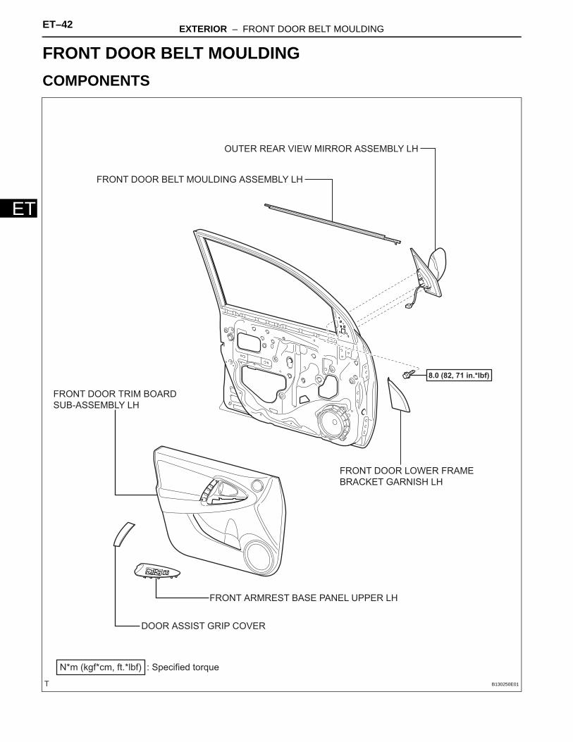
BODYEXTERIORFRONT DOOR BELT MOULDINGCOMPONENTS
FRONT ARMREST BASE PANEL UPPER LH
FRONT DOOR BELT MOULDING ASSEMBLY LH
FRONT DOOR LOWER FRAME
BRACKET GARNISH LH
FRONT DOOR TRIM BOARD
SUB-ASSEMBLY LH
OUTER REAR VIEW MIRROR ASSEMBLY LH
: Specified torqueN*m (kgf*cm, ft.*lbf)
8.0 (82, 71 in.*lbf)
DOOR ASSIST GRIP COVER
B130250E01
EXTERIOR – FRONT DOOR BELT MOULDING ET–43
ET
REMOVALHINT:• Use the same procedures for the RH side and LH side.• The procedures listed below are for the LH side.
1. DISCONNECT CABLE FROM NEGATIVE BATTERY TERMINALNOTICE:Wait at least 90 seconds after disconnecting the cable from the negative (-) battery terminal to prevent airbag and seat belt pretensioner activation.
2. REMOVE FRONT DOOR LOWER FRAME BRACKET GARNISH LH (See page ED-19)
3. REMOVE FRONT ARMREST BASE PANEL UPPER LH (See page ED-19)
4. REMOVE FRONT DOOR TRIM BOARD SUB-ASSEMBLY LH (See page ED-20)
5. REMOVE OUTER REAR VIEW MIRROR ASSEMBLY LH (See page MI-8)
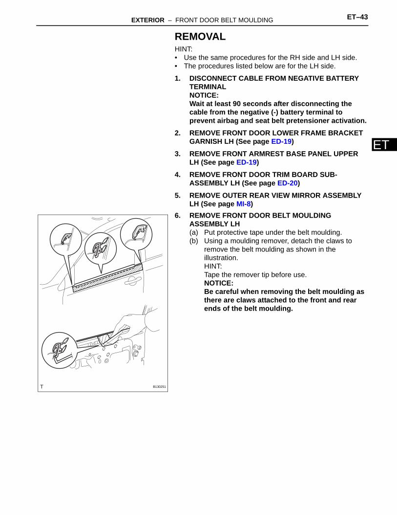
6. REMOVE FRONT DOOR BELT MOULDING ASSEMBLY LH(a) Put protective tape under the belt moulding.(b) Using a moulding remover, detach the claws to
remove the belt moulding as shown in the illustration.HINT:Tape the remover tip before use.NOTICE:Be careful when removing the belt moulding as there are claws attached to the front and rear ends of the belt moulding.
B130251
ET–44 EXTERIOR – FRONT DOOR BELT MOULDING
ET
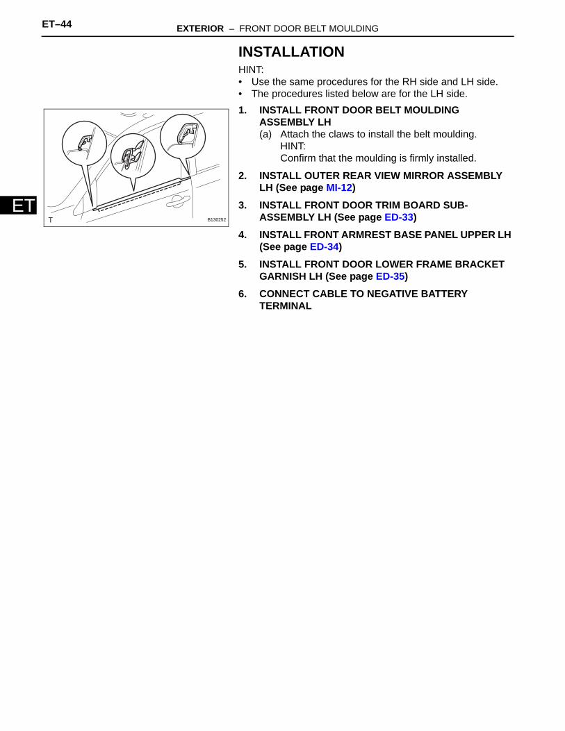
INSTALLATIONHINT:• Use the same procedures for the RH side and LH side.• The procedures listed below are for the LH side.1. INSTALL FRONT DOOR BELT MOULDING
ASSEMBLY LH(a) Attach the claws to install the belt moulding.
HINT:Confirm that the moulding is firmly installed.
2. INSTALL OUTER REAR VIEW MIRROR ASSEMBLY LH (See page MI-12)
3. INSTALL FRONT DOOR TRIM BOARD SUB-ASSEMBLY LH (See page ED-33)
4. INSTALL FRONT ARMREST BASE PANEL UPPER LH (See page ED-34)
5. INSTALL FRONT DOOR LOWER FRAME BRACKET GARNISH LH (See page ED-35)
6. CONNECT CABLE TO NEGATIVE BATTERY TERMINAL
B130252
EXTERIOR – REAR DOOR BELT MOULDING ET–45
ET
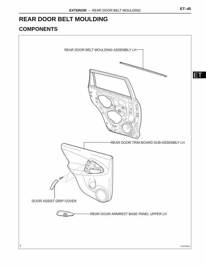
BODYEXTERIORREAR DOOR BELT MOULDINGCOMPONENTS
REAR DOOR ARMREST BASE PANEL UPPER LH
REAR DOOR BELT MOULDING ASSEMBLY LH
REAR DOOR TRIM BOARD SUB-ASSEMBLY LH
DOOR ASSIST GRIP COVER
B130253E01
ET–46 EXTERIOR – REAR DOOR BELT MOULDING
ET
REMOVALHINT:• Use the same procedures for the RH side and LH side.• The procedures listed below are for the LH side.
1. DISCONNECT CABLE FROM NEGATIVE BATTERY TERMINALCAUTION:Wait at least 90 seconds after disconnecting the cable from the negative (-) battery terminal to prevent airbag and seat belt pretensioner activation.
2. REMOVE REAR DOOR ARMREST BASE PANEL UPPER LH (See page ED-40)
3. REMOVE REAR DOOR TRIM BOARD SUB-ASSEMBLY LH (See page ED-40)
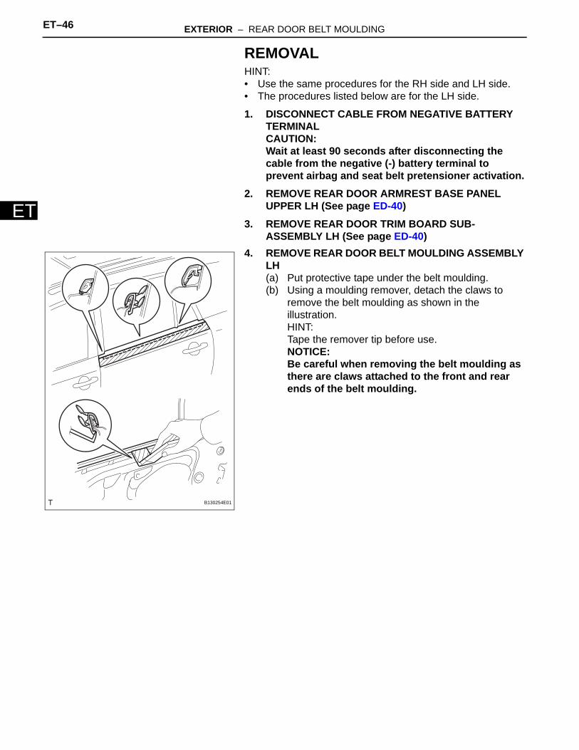
4. REMOVE REAR DOOR BELT MOULDING ASSEMBLY LH(a) Put protective tape under the belt moulding.(b) Using a moulding remover, detach the claws to
remove the belt moulding as shown in the illustration.HINT:Tape the remover tip before use.NOTICE:Be careful when removing the belt moulding as there are claws attached to the front and rear ends of the belt moulding.
C130254-A20B130254E01
EXTERIOR – FRONT PILLAR UPPER COVER ET–47
ET
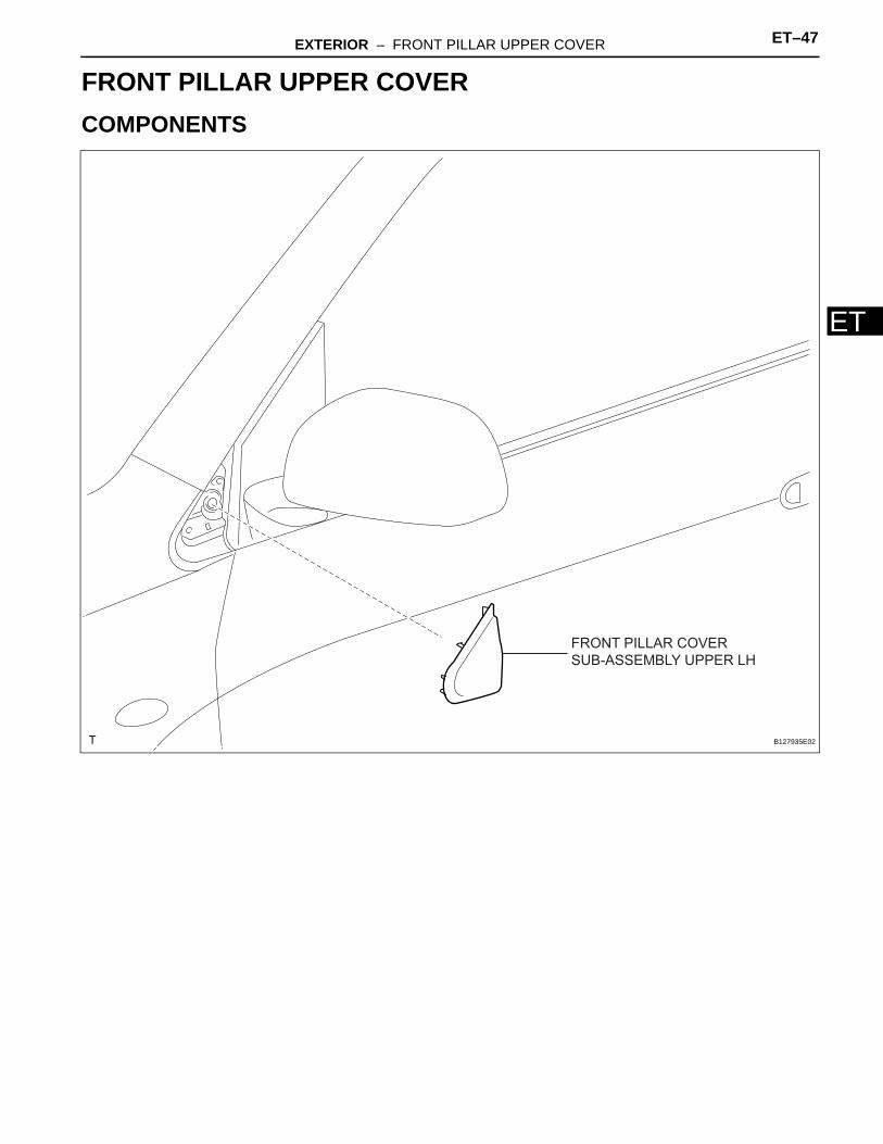
BODYEXTERIORFRONT PILLAR UPPER COVERCOMPONENTS
FRONT PILLAR COVER SUB-ASSEMBLY UPPER LH
B127935E02
ET–48 EXTERIOR – FRONT PILLAR UPPER COVER
ET
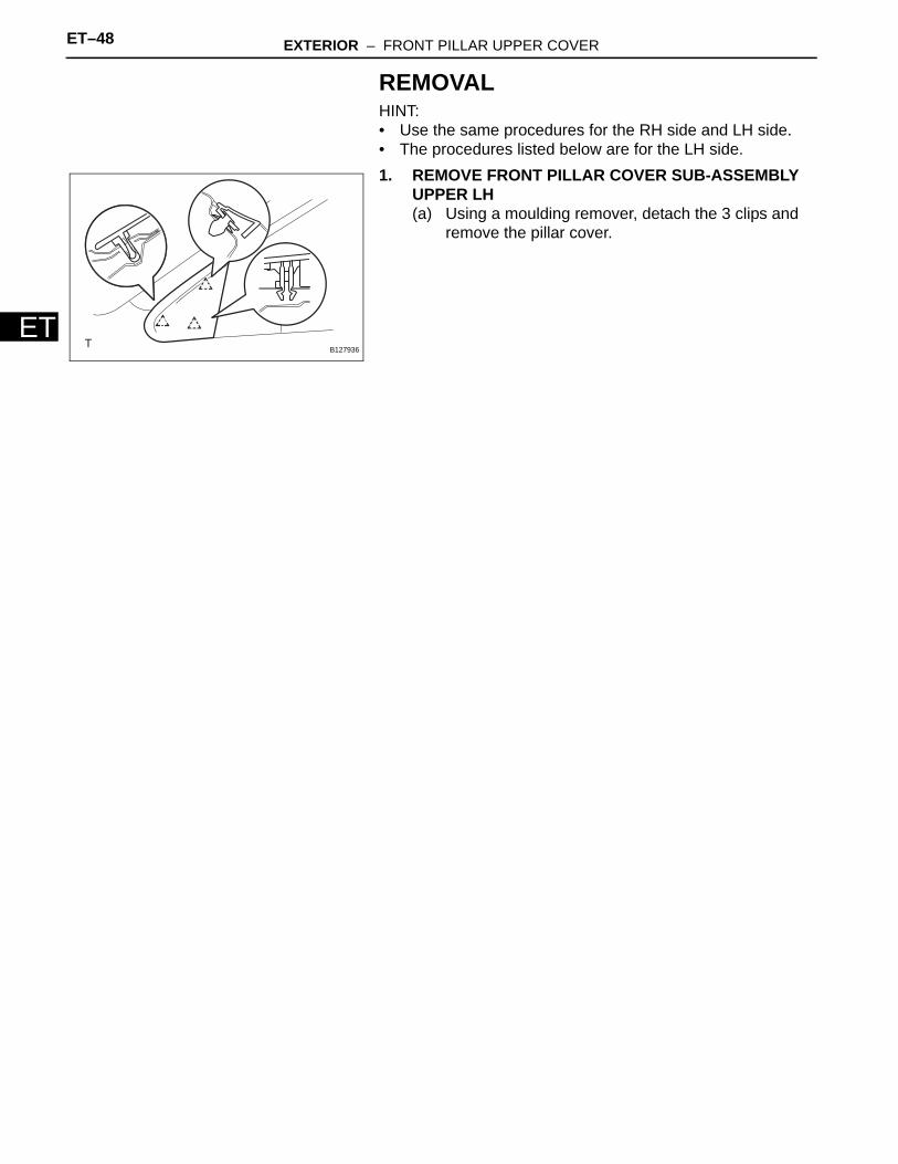
REMOVALHINT:• Use the same procedures for the RH side and LH side.• The procedures listed below are for the LH side.1. REMOVE FRONT PILLAR COVER SUB-ASSEMBLY
UPPER LH(a) Using a moulding remover, detach the 3 clips and
remove the pillar cover.
B127936
EXTERIOR – REAR DOOR BELT MOULDING ET–47
ET
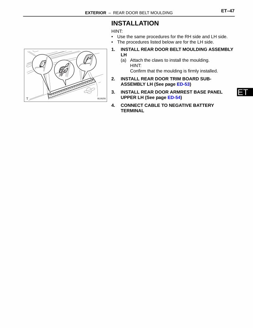
INSTALLATIONHINT:• Use the same procedures for the RH side and LH side.• The procedures listed below are for the LH side.1. INSTALL REAR DOOR BELT MOULDING ASSEMBLY
LH(a) Attach the claws to install the moulding.
HINT:Confirm that the moulding is firmly installed.
2. INSTALL REAR DOOR TRIM BOARD SUB-ASSEMBLY LH (See page ED-53)
3. INSTALL REAR DOOR ARMREST BASE PANEL UPPER LH (See page ED-54)
4. CONNECT CABLE TO NEGATIVE BATTERY TERMINAL
B130255
EXTERIOR – FRONT PILLAR UPPER COVER ET–49
ET
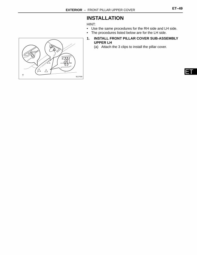
INSTALLATIONHINT:• Use the same procedures for the RH side and LH side.• The procedures listed below are for the LH side.1. INSTALL FRONT PILLAR COVER SUB-ASSEMBLY
UPPER LH(a) Attach the 3 clips to install the pillar cover.
B127936
EXTERIOR – ROOF DRIP SIDE FINISH MOULDING ET–49
ET
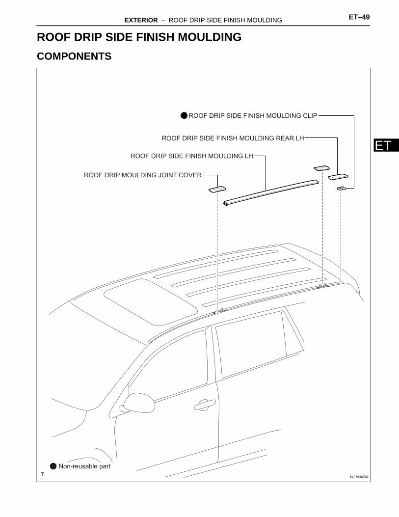
BODYEXTERIORROOF DRIP SIDE FINISH MOULDINGCOMPONENTS
ROOF DRIP SIDE FINISH MOULDING LH
ROOF DRIP SIDE FINISH MOULDING REAR LH
ROOF DRIP SIDE FINISH MOULDING CLIP
Non-reusable part
ROOF DRIP MOULDING JOINT COVER
B127946E02
ET–50 EXTERIOR – ROOF DRIP SIDE FINISH MOULDING
ET
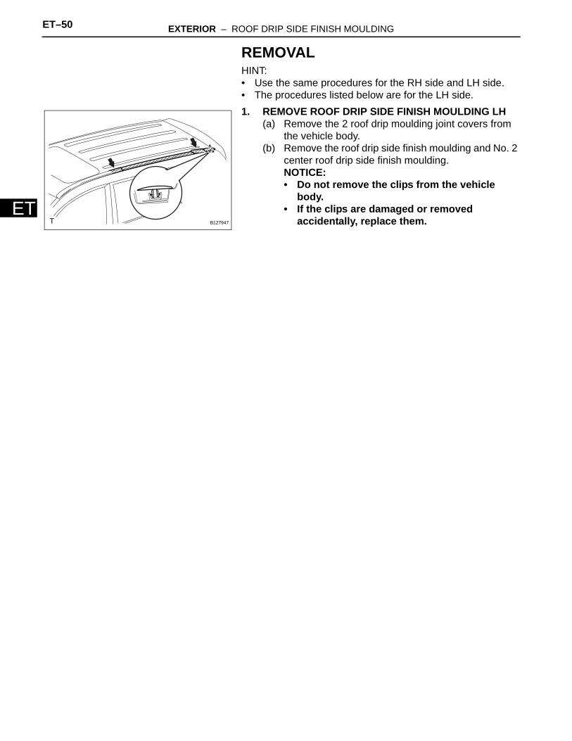
REMOVALHINT:• Use the same procedures for the RH side and LH side.• The procedures listed below are for the LH side.1. REMOVE ROOF DRIP SIDE FINISH MOULDING LH
(a) Remove the 2 roof drip moulding joint covers from the vehicle body.
(b) Remove the roof drip side finish moulding and No. 2 center roof drip side finish moulding.NOTICE:• Do not remove the clips from the vehicle
body.• If the clips are damaged or removed
accidentally, replace them.B127947
EXTERIOR – ROOF DRIP SIDE FINISH MOULDING ET–51
ET
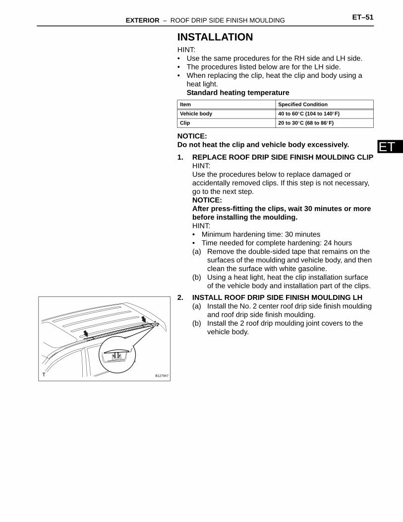
INSTALLATIONHINT:• Use the same procedures for the RH side and LH side.• The procedures listed below are for the LH side.• When replacing the clip, heat the clip and body using a
heat light.Standard heating temperature
NOTICE:Do not heat the clip and vehicle body excessively.1. REPLACE ROOF DRIP SIDE FINISH MOULDING CLIP
HINT:Use the procedures below to replace damaged or accidentally removed clips. If this step is not necessary, go to the next step.NOTICE:After press-fitting the clips, wait 30 minutes or more before installing the moulding.HINT:• Minimum hardening time: 30 minutes• Time needed for complete hardening: 24 hours(a) Remove the double-sided tape that remains on the
surfaces of the moulding and vehicle body, and then clean the surface with white gasoline.
(b) Using a heat light, heat the clip installation surface of the vehicle body and installation part of the clips.
2. INSTALL ROOF DRIP SIDE FINISH MOULDING LH(a) Install the No. 2 center roof drip side finish moulding
and roof drip side finish moulding.(b) Install the 2 roof drip moulding joint covers to the
vehicle body.
Item Specified Condition
Vehicle body 40 to 60°C (104 to 140°F)
Clip 20 to 30°C (68 to 86°F)
B127947
ET–52 EXTERIOR – OUTSIDE MOULDING
ET
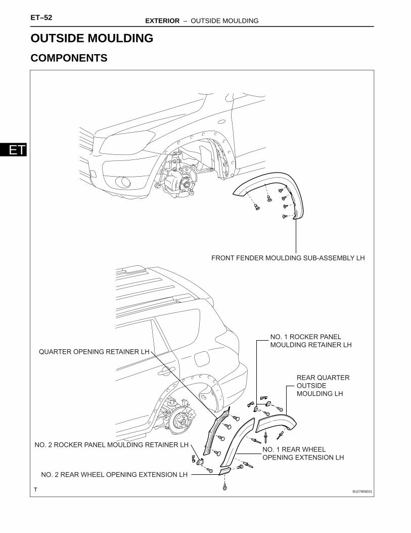
BODYEXTERIOROUTSIDE MOULDINGCOMPONENTS
FRONT FENDER MOULDING SUB-ASSEMBLY LH
NO. 1 REAR WHEEL
OPENING EXTENSION LH
NO. 2 REAR WHEEL OPENING EXTENSION LH
NO. 1 ROCKER PANEL
MOULDING RETAINER LH
NO. 2 ROCKER PANEL MOULDING RETAINER LH
QUARTER OPENING RETAINER LH
REAR QUARTER
OUTSIDE
MOULDING LH
B127955E01
EXTERIOR – OUTSIDE MOULDING ET–53
ET
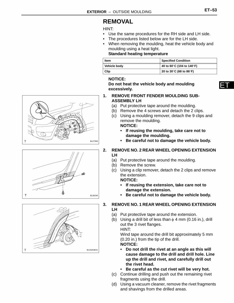
REMOVALHINT:• Use the same procedures for the RH side and LH side.• The procedures listed below are for the LH side.• When removing the moulding, heat the vehicle body and
moulding using a heat light.Standard heating temperature
NOTICE:Do not heat the vehicle body and moulding excessively.
1. REMOVE FRONT FENDER MOULDING SUB-ASSEMBLY LH(a) Put protective tape around the moulding.(b) Remove the 4 screws and detach the 2 clips.(c) Using a moulding remover, detach the 9 clips and
remove the moulding.NOTICE:• If reusing the moulding, take care not to
damage the moulding.• Be careful not to damage the vehicle body.
2. REMOVE NO. 2 REAR WHEEL OPENING EXTENSION LH(a) Put protective tape around the moulding.(b) Remove the screw.(c) Using a clip remover, detach the 2 clips and remove
the extension.NOTICE:• If reusing the extension, take care not to
damage the extension.• Be careful not to damage the vehicle body.
3. REMOVE NO. 1 REAR WHEEL OPENING EXTENSION LH(a) Put protective tape around the extension.(b) Using a drill bit of less than φ 4 mm (0.16 in.), drill
out the 3 rivet flanges.HINT:Wind tape around the drill bit approximately 5 mm (0.20 in.) from the tip of the drill.NOTICE:• Do not drill the rivet at an angle as this will
cause damage to the drill and drill hole. Line up the drill and rivet, and carefully drill out the rivet head.
• Be careful as the cut rivet will be very hot.(c) Continue drilling and push out the remaining rivet
fragments using the drill.(d) Using a vacuum cleaner, remove the rivet fragments
and shavings from the drilled areas.
Item Specified Condition
Vehicle body 40 to 60°C (104 to 140°F)
Clip 20 to 30°C (68 to 86°F)
B127958
B130248
B133203E01
ET–54 EXTERIOR – OUTSIDE MOULDING
ET
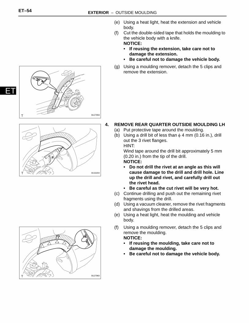
(e) Using a heat light, heat the extension and vehicle body.
(f) Cut the double-sided tape that holds the moulding to the vehicle body with a knife.NOTICE:• If reusing the extension, take care not to
damage the extension.• Be careful not to damage the vehicle body.
(g) Using a moulding remover, detach the 5 clips and remove the extension.
4. REMOVE REAR QUARTER OUTSIDE MOULDING LH(a) Put protective tape around the moulding.(b) Using a drill bit of less than φ 4 mm (0.16 in.), drill
out the 3 rivet flanges.HINT:Wind tape around the drill bit approximately 5 mm (0.20 in.) from the tip of the drill.NOTICE:• Do not drill the rivet at an angle as this will
cause damage to the drill and drill hole. Line up the drill and rivet, and carefully drill out the rivet head.
• Be careful as the cut rivet will be very hot.(c) Continue drilling and push out the remaining rivet
fragments using the drill.(d) Using a vacuum cleaner, remove the rivet fragments
and shavings from the drilled areas.(e) Using a heat light, heat the moulding and vehicle
body.(f) Using a moulding remover, detach the 5 clips and
remove the moulding.NOTICE:• If reusing the moulding, take care not to
damage the moulding.• Be careful not to damage the vehicle body.
B127959
B133204
B127960
EXTERIOR – OUTSIDE MOULDING ET–55
ET
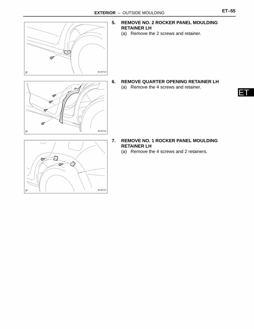
5. REMOVE NO. 2 ROCKER PANEL MOULDING RETAINER LH(a) Remove the 2 screws and retainer.
6. REMOVE QUARTER OPENING RETAINER LH(a) Remove the 4 screws and retainer.
7. REMOVE NO. 1 ROCKER PANEL MOULDING RETAINER LH(a) Remove the 4 screws and 2 retainers.
B133713
B133714
B133715
ET–56 EXTERIOR – OUTSIDE MOULDING
ET
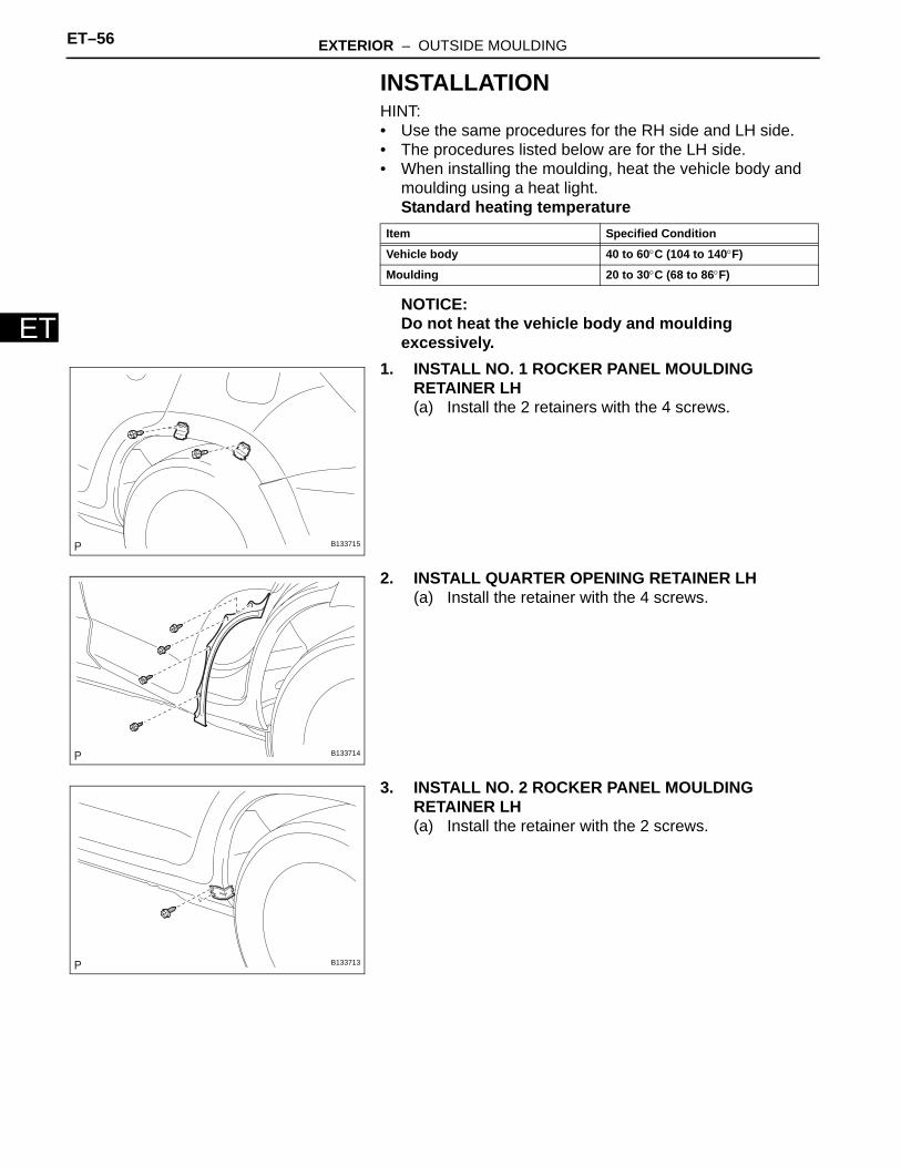
INSTALLATIONHINT:• Use the same procedures for the RH side and LH side.• The procedures listed below are for the LH side.• When installing the moulding, heat the vehicle body and
moulding using a heat light.Standard heating temperature
NOTICE:Do not heat the vehicle body and moulding excessively.
1. INSTALL NO. 1 ROCKER PANEL MOULDING RETAINER LH(a) Install the 2 retainers with the 4 screws.
2. INSTALL QUARTER OPENING RETAINER LH(a) Install the retainer with the 4 screws.
3. INSTALL NO. 2 ROCKER PANEL MOULDING RETAINER LH(a) Install the retainer with the 2 screws.
Item Specified Condition
Vehicle body 40 to 60°C (104 to 140°F)
Moulding 20 to 30°C (68 to 86°F)
B133715
B133714
B133713
EXTERIOR – OUTSIDE MOULDING ET–57
ET
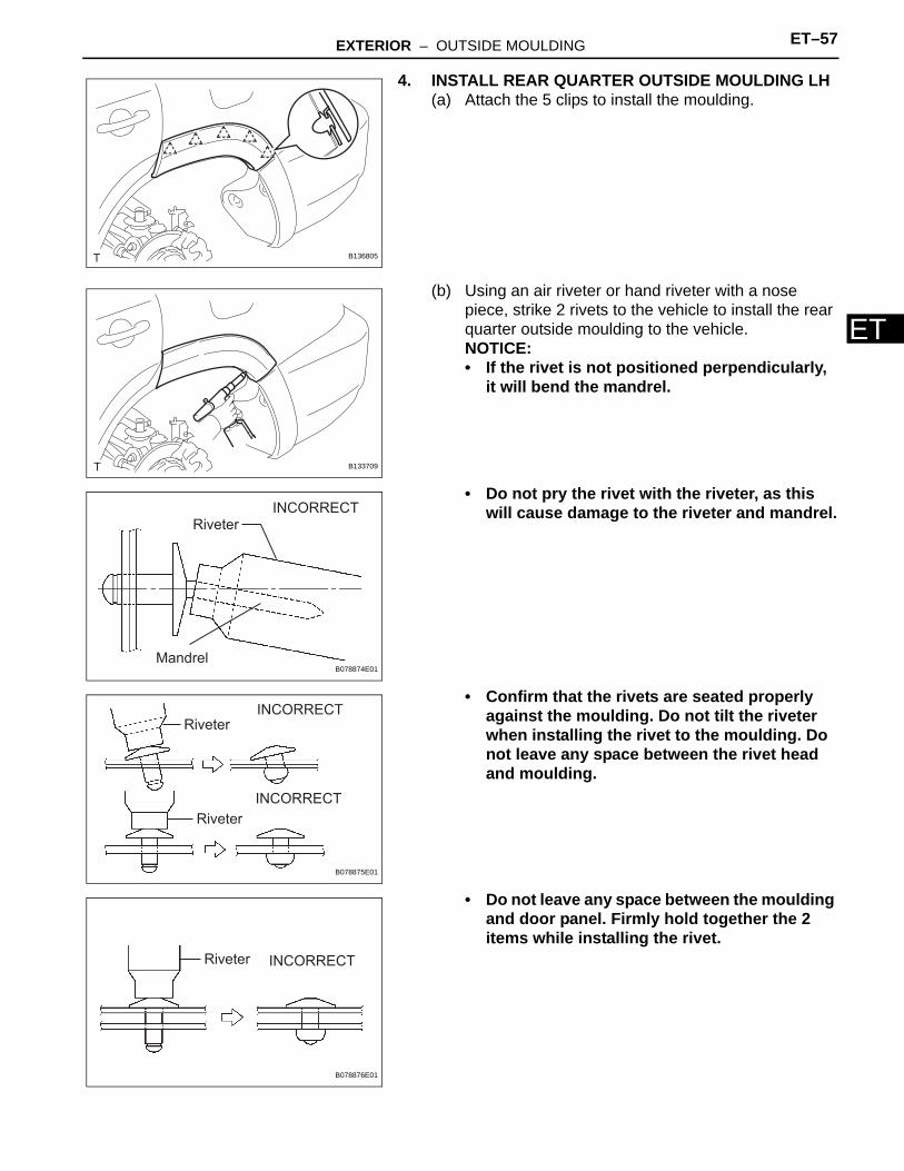
4. INSTALL REAR QUARTER OUTSIDE MOULDING LH(a) Attach the 5 clips to install the moulding.
(b) Using an air riveter or hand riveter with a nose piece, strike 2 rivets to the vehicle to install the rear quarter outside moulding to the vehicle.NOTICE:• If the rivet is not positioned perpendicularly,
it will bend the mandrel.
• Do not pry the rivet with the riveter, as this will cause damage to the riveter and mandrel.
• Confirm that the rivets are seated properly against the moulding. Do not tilt the riveter when installing the rivet to the moulding. Do not leave any space between the rivet head and moulding.
• Do not leave any space between the moulding and door panel. Firmly hold together the 2 items while installing the rivet.
B136805
B133709
INCORRECT
Riveter
MandrelB078874E01
INCORRECT
INCORRECT
Riveter
Riveter
B078875E01
Riveter INCORRECT
B078876E01
ET–58 EXTERIOR – OUTSIDE MOULDING
ET
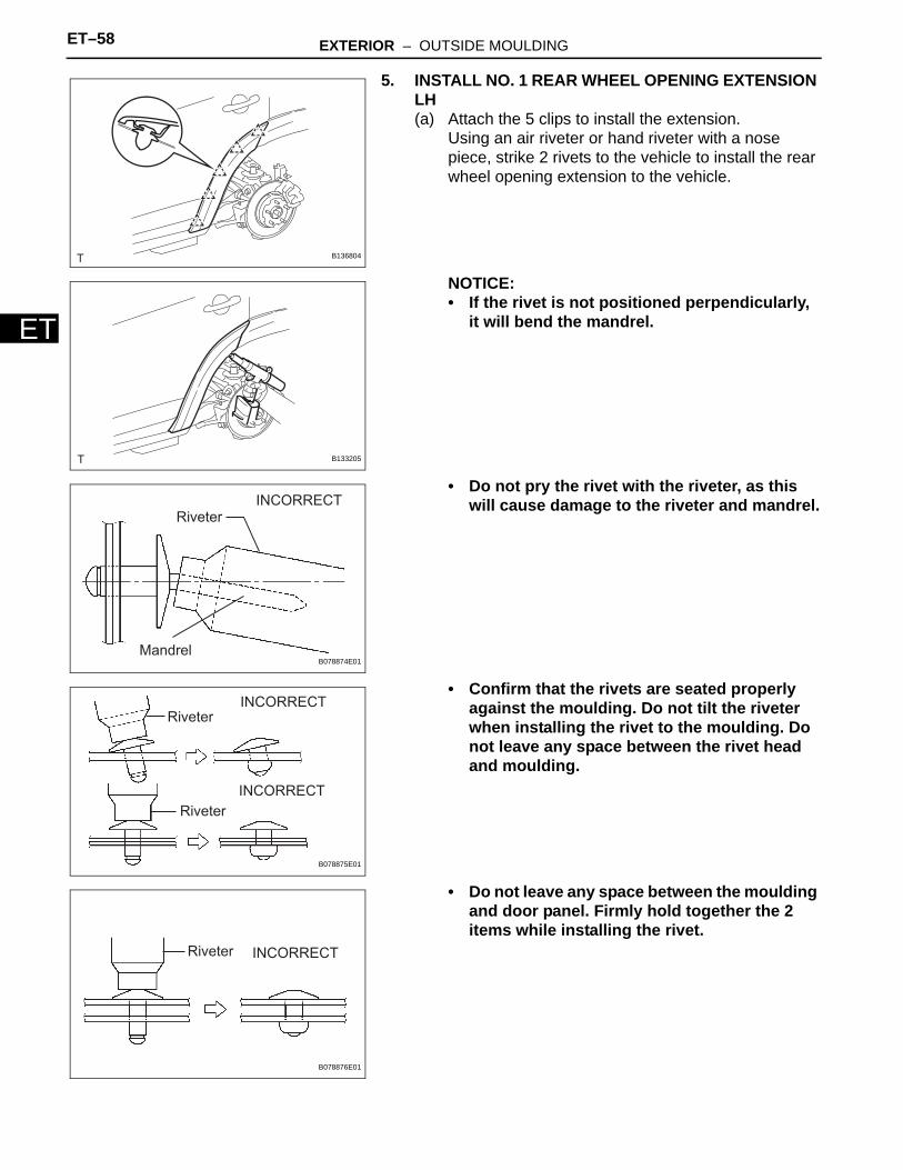
5. INSTALL NO. 1 REAR WHEEL OPENING EXTENSION LH(a) Attach the 5 clips to install the extension.
Using an air riveter or hand riveter with a nose piece, strike 2 rivets to the vehicle to install the rear wheel opening extension to the vehicle.
NOTICE:• If the rivet is not positioned perpendicularly,
it will bend the mandrel.
• Do not pry the rivet with the riveter, as this will cause damage to the riveter and mandrel.
• Confirm that the rivets are seated properly against the moulding. Do not tilt the riveter when installing the rivet to the moulding. Do not leave any space between the rivet head and moulding.
• Do not leave any space between the moulding and door panel. Firmly hold together the 2 items while installing the rivet.
B136804
B133205
INCORRECT
Riveter
MandrelB078874E01
INCORRECT
INCORRECT
Riveter
Riveter
B078875E01
Riveter INCORRECT
B078876E01
EXTERIOR – OUTSIDE MOULDING ET–59
ET
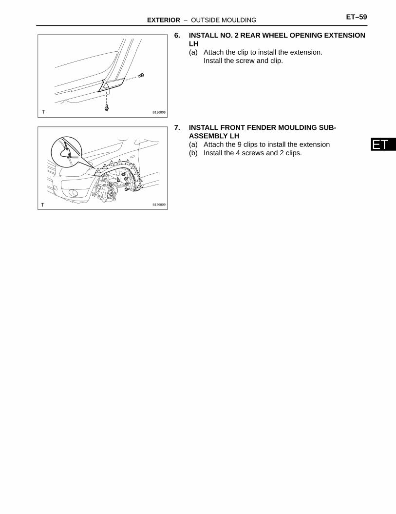
6. INSTALL NO. 2 REAR WHEEL OPENING EXTENSION LH(a) Attach the clip to install the extension.
Install the screw and clip.
7. INSTALL FRONT FENDER MOULDING SUB-ASSEMBLY LH(a) Attach the 9 clips to install the extension(b) Install the 4 screws and 2 clips.
B136808
B136809
EXTERIOR – BACK DOOR OUTSIDE GARNISH ET–59
ET
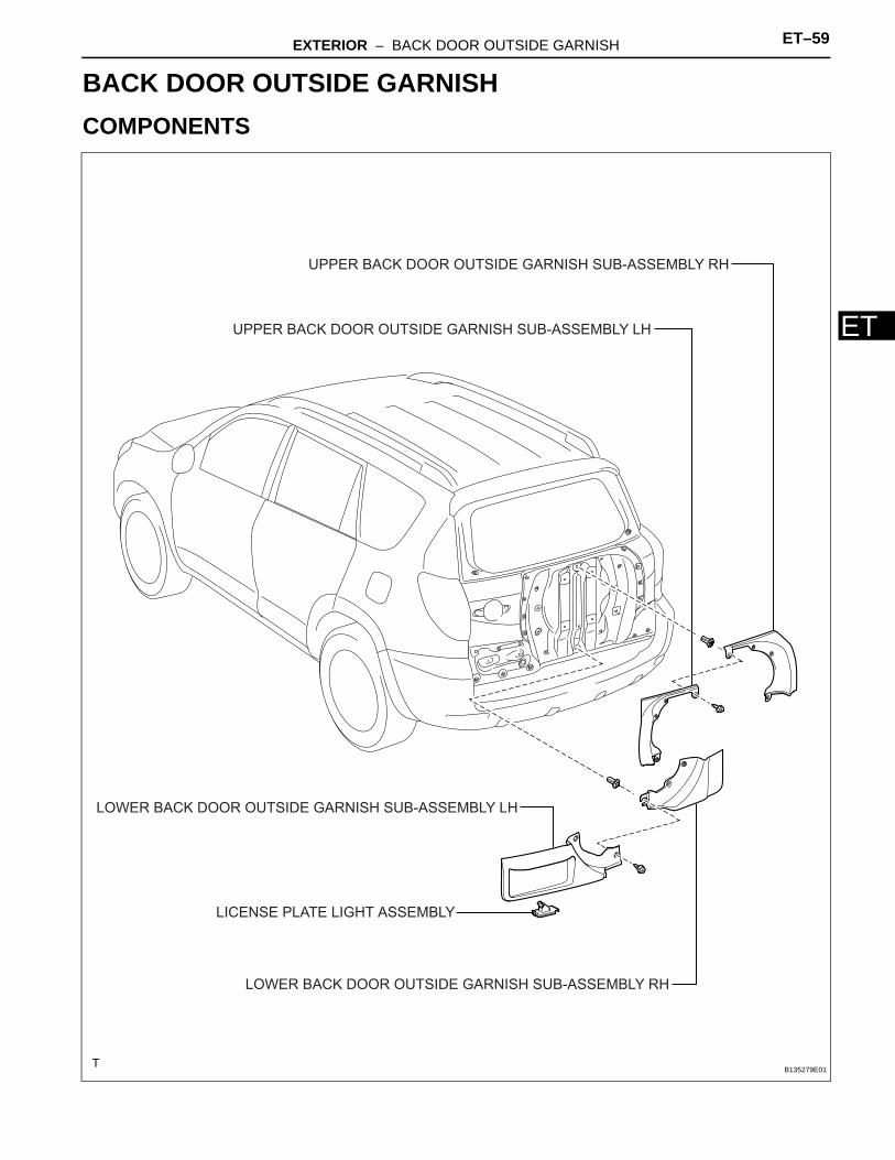
BODYEXTERIORBACK DOOR OUTSIDE GARNISHCOMPONENTS
LOWER BACK DOOR OUTSIDE GARNISH SUB-ASSEMBLY LH
LOWER BACK DOOR OUTSIDE GARNISH SUB-ASSEMBLY RH
UPPER BACK DOOR OUTSIDE GARNISH SUB-ASSEMBLY LH
UPPER BACK DOOR OUTSIDE GARNISH SUB-ASSEMBLY RH
LICENSE PLATE LIGHT ASSEMBLY
B135279E01
ET–60 EXTERIOR – BACK DOOR OUTSIDE GARNISH
ET
REMOVAL1. DISCONNECT CABLE FROM NEGATIVE BATTERY
TERMINALCAUTION:Wait at least 90 seconds after disconnecting the cable from the negative (-) battery terminal to prevent airbag and seat belt pretensioner activation.
2. REMOVE BACK DOOR CENTER GARNISH (See page ED-59)
3. REMOVE BACK DOOR SIDE GARNISH LH (See page ED-59)
4. REMOVE BACK DOOR SIDE GARNISH RH (See page ED-59)
5. REMOVE BACK DOOR COURTESY LIGHT SWITCH ASSEMBLY (See page LI-122)
6. REMOVE BACK DOOR TRIM BOARD (See page ED-59)
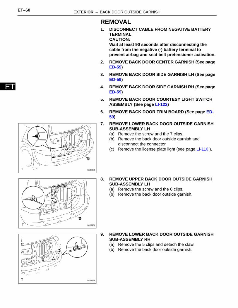
7. REMOVE LOWER BACK DOOR OUTSIDE GARNISH SUB-ASSEMBLY LH(a) Remove the screw and the 7 clips.(b) Remove the back door outside garnish and
disconnect the connector.(c) Remove the license plate light (see page LI-110 ).
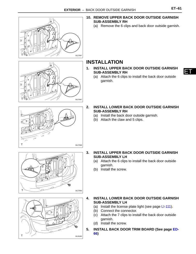
8. REMOVE UPPER BACK DOOR OUTSIDE GARNISH SUB-ASSEMBLY LH(a) Remove the screw and the 6 clips.(b) Remove the back door outside garnish.
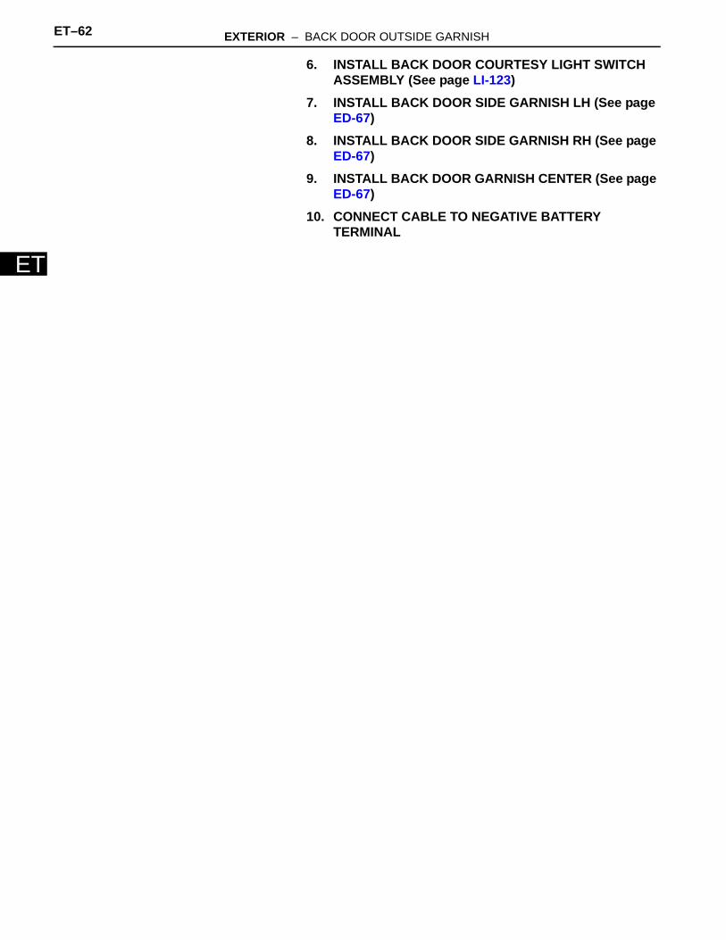
9. REMOVE LOWER BACK DOOR OUTSIDE GARNISH SUB-ASSEMBLY RH(a) Remove the 5 clips and detach the claw.(b) Remove the back door outside garnish.
B135280
B127966
B127968
EXTERIOR – BACK DOOR OUTSIDE GARNISH ET–61
ET
10. REMOVE UPPER BACK DOOR OUTSIDE GARNISH SUB-ASSEMBLY RH(a) Remove the 6 clips and back door outside garnish.
INSTALLATION1. INSTALL UPPER BACK DOOR OUTSIDE GARNISH
SUB-ASSEMBLY RH(a) Attach the 6 clips to install the back door outside
garnish.
2. INSTALL LOWER BACK DOOR OUTSIDE GARNISH SUB-ASSEMBLY RH(a) Install the back door outside garnish.(b) Attach the claw and 5 clips.
3. INSTALL UPPER BACK DOOR OUTSIDE GARNISH SUB-ASSEMBLY LH(a) Attach the 6 clips to install the back door outside
garnish.(b) Install the screw.
4. INSTALL LOWER BACK DOOR OUTSIDE GARNISH SUB-ASSEMBLY LH(a) Install the license plate light (see page LI-111).(b) Connect the connector.(c) Attach the 7 clips to install the back door outside
garnish.(d) Install the screw.
5. INSTALL BACK DOOR TRIM BOARD (See page ED-66)
B127967
B127967
B127968
B127966
B135280
ET–62 EXTERIOR – BACK DOOR OUTSIDE GARNISH
ET
6. INSTALL BACK DOOR COURTESY LIGHT SWITCH ASSEMBLY (See page LI-123)
7. INSTALL BACK DOOR SIDE GARNISH LH (See page ED-67)
8. INSTALL BACK DOOR SIDE GARNISH RH (See page ED-67)
9. INSTALL BACK DOOR GARNISH CENTER (See page ED-67)
10. CONNECT CABLE TO NEGATIVE BATTERY TERMINAL
![Strength Enhancement of Car Front Bumper for Slow … · Strength Enhancement of Car Front Bumper for Slow Speed ... Marzbanrad, et al [1] studied a front bumper beam made ... 15%](https://img.dokumen.tips/doc/110x75/5b0791c47f8b9a58148e78cb/strength-enhancement-of-car-front-bumper-for-slow-enhancement-of-car-front-bumper.jpg)