Embed Size (px)
Citation preview
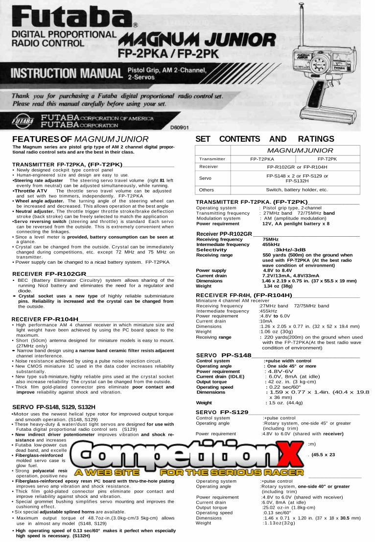
FEATURES OF MAGNUM JUNIORThe Magnum series are pistol grip type of AM 2 channel digital propor-tional radio control sets and are the best in their class.
TRANSMITTER FP-T2PKA, (FP-T2PK)_____________• Newly designed cockpit type control panel• Human-engineered size and design are easy to use.•Steering rate adjuster The steering servo travel volume (right 81 left
evenly from neutral) can be adjusted simultaneously, while running.•Throttle ATV The throttle servo travel volume can be adjusted
and set with two trimmers, independently. FP-T2PKA• Wheel angle adjuster. The turning angle of the steering wheel can
be increased and decreased. This allows operation at the best angle• Neutral adjuster. The throttle trigger thrott le stroke/brake deflection
stroke (back stroke) can be freely selected to match the application•Servo reversing switch (steering and thrott le) is standard Each servo
can be reversed from the outside. This is extremely convenient whenconnecting the linkages.
• Since a level meter is provided, battery consumption can be seen ata glance.
• Crystal can be changed from the outside. Crystal can be immediatelychanged during competitions, etc. except 72 MHz and 75 MHz ontransmitter.
• Power supply can be changed to a nicad battery system. FP-T2PKA
RECEIVER FP-R102GR_____________________• BEC (Battery Eliminator Circuitry) system allows sharing of the
running Nicd battery and eliminates the need for a regulator anddiode.
• Crystal socket uses a new type of highly reliable subminiaturepins. Reliability is increased and the crystal can be changed fromthe outside.
RECEIVER FP-R104H_______________________• High performance AM 4 channel receiver in which miniature size and
light weight have been achieved by using the PC board space to themaximum.
• Short (50cm) antenna designed for miniature models is easy to mount.(27MHz only)
• Narrow band design using a narrow band ceramic filter resists adjacentchannel interference.
• Noise resistance achieved by using a pulse noise rejection circuit.• New CMOS miniature 1C used in the data coder increases reliability
substantially.• New type sub miniature, highly reliable pins used at the crystal socket
also increase reliability The crystal can be changed from the outside.• Thick film gold-plated connector pins eliminate poor contact and
improve reliability against shock and vibration.
SERVO FP-S148, S129, S132H•Motor uses the newest helical type rotor for improved output torque
and smooth operation. (S148, S129)• These heavy-duty & water/dust tight servos are designed for use with
Futaba digital proportional radio control sets (S129)• New indirect driver potentiometer improves vibration and shock re-
sistance and increases neutral precision tremendously.• Futaba low-power custom 1C provides high starting torque, narrow
dead band, and excellent trackability.• Fiberglass-reinforced PBT (polybutylene terephthalate) injection
molded servo case is mechanically strong and invulnerable againstglow fuel.
• Strong polyacetal resin ultra-precision servo gear features smoothoperation, positive neutral, and very l i t t le backlash.
• Fiberglass-reinforced epoxy resin PC board with thru-the-hole platingimproves servo amp vibration and shock resistance.
• Thick film gold-plated connector pins eliminate poor contact andimprove reliability against shock and vibration.
• Special grommet bushing simplifies servo mounting and improves thecushioning effect.
• Six special adjustable splined horns are available.• Maximum output torque of 48.7oz-in.(3.0kg-cm/3 5kg-cm) allows
use in almost any model (S148, S129)• High operating speed of 0.13 sec/60° makes it perfect when especially
high speed is necessary. (S132H)
SET CONTENTS AND RATINGS
Transmitter
Receiver
Servo
Others
MAGNUM JUNIORFP-T2PKA
FP-R102GR or FP-R104H
FP-S148 x 2 or FP-S129 orFP-S132H
Switch, battery holder, etc.
FP-T2PK
TRANSMITTER FP-T2PKA. (FP-T2PK)_____________Operating system : Pistol grip type, 2-channelTransmitting frequency : 27MHz band 72/75MHz bandModulation system : AM (amplitude modulation)Power requirement 12V, AA penlight battery x 8
Receiver PP-R102GR ________________________Receiving frequency 75MHzIntermediate frequency 455kHzSelectivity :3kHz/-3dBReceiving range 550 yards (500m) on the ground when
used with FP-T2PKA (At the best radiowave condition of environment)
Power supply 4.8V to 8.4VCurrent drain 7.2V/13mA, 4.8V/33mADimensions 1.46 x 2.19 x 0.75 in. (37 x 55.5 x 19 mm)Weight 1.34 oz (38g)
RECEIVER FP-R4H, (FP-R104H)_________________Miniature 4 channel AM receiverReceiving frequency :27MHz band 72/75MHz bandIntermediate frequency :455kHzPower requirement :4.8V to 6.0VCurrent drain :10mADimensions :1.26 x 2.05 x 0.77 in. (32 x 52 x 19.4 mm)Weight :1.06 oz (30g)Receiving range : 220 yards(200m) on the ground when used
with the FP-T2PKA(At the best radio wavecondition of environment)
SERVO PP-S148__________________________Control system :+pulse width controlOperating angle : One side 45° or morePower requirement : 4.8V-6VCurrent drain (IDLE) : 6.0V, 8mA (at idle)Output torque : 42 oz. in. (3 kg-cm)Operating speed : 0.22 sec/60°Dimensions : 1.59 x 0.77 x 1.4in. (40.4 x 19.8
x 36 mm) Weight : 1.5 oz. (44.4g)
SERVO FP-S129____________________________Control system :+pulse controlOperating angle :Rotary system, one-side 45" or greater
(including trim)Power requirement :4.8V to 6.0V (shared with receiver)Current drain :6.0V, 8mA (at idle)Output torque :48.7 oz-in (3.5kg-cm)Operating speed :0.25 sec /60"Dimensions :1.79 x 0.9 x 1.71 in. (45.5 x 23
x 43 5 mm)Weight :2.1 oz (60g)
SERVO FP-S132H___________________________Operating system :+pulse controlOperating angle :Rotary system, one-side 40" or greater
(including trim)Power requirement :4.8V to 6.0V (shared with receiver)Current drain :6.0V, 8mA (at idle)Output torque :25.02 oz-in (1.8kg-cm)Operating speed :0.13 sec/60°Dimensions :1.46 x 0.71 x 1.20 in. (37 x 18 x 30.5 mm)Weight :1 .13oz(32g)
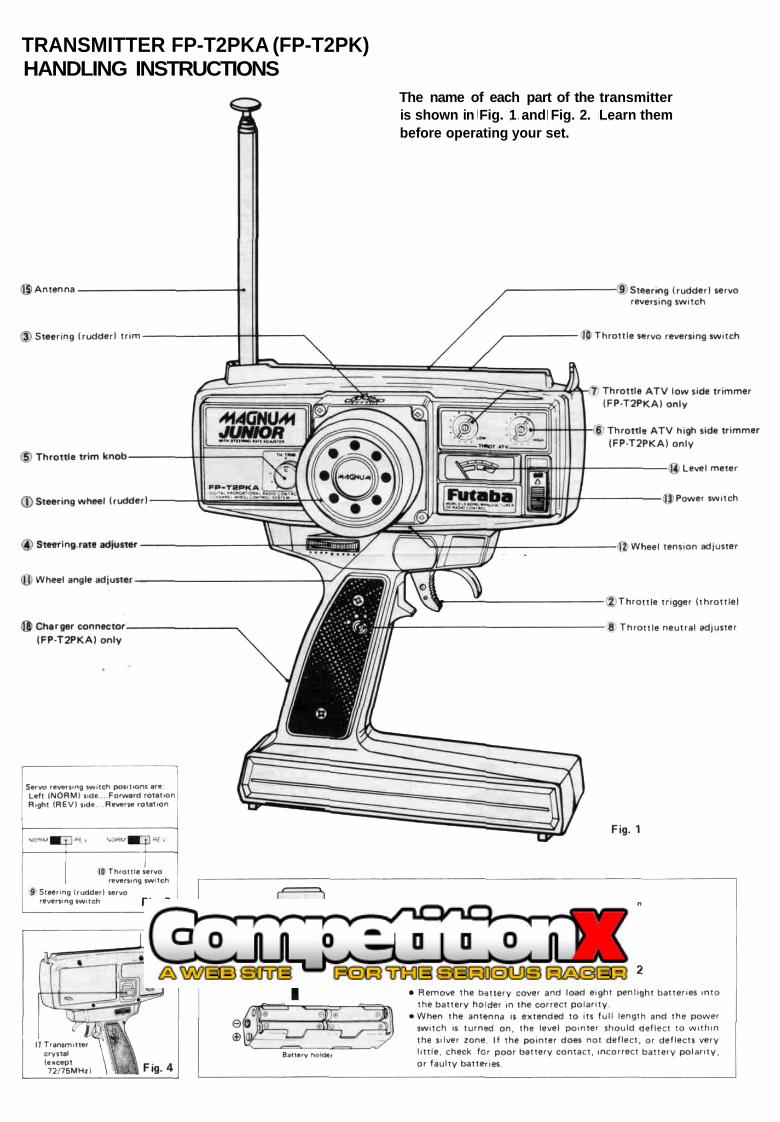
TRANSMITTER FP-T2PKA (FP-T2PK)HANDLING INSTRUCTIONS
The name of each part of the transmitteris shown in Fig. 1 and Fig. 2. Learn thembefore operating your set.
The servo reversing switches are assumed to be in the normalposition in the descriptions in this section. When the servoswitches are in the reverse position, operation is the oppositeof that described here.
(1) Steering wheel (rudder)Steering (rudder) operation.
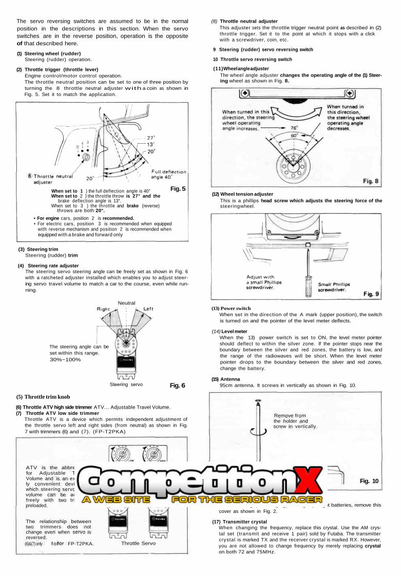
(2) Throttle trigger (throttle lever)Engine control/motor control operation.The throttle neutral position can be set to one of three position byturning the 8 throttle neutral adjuster wi th a coin as shown inFig. 5. Set it to match the application.
When set to 1 ) the full deflection angle is 40°When set to 2 ) the throttle throw is 27° and the
brake deflection angle is 13°.When set to 3 ) the throttle and brake (reverse)
throws are both 20°.• For engine cars, position 2 is recommended.• For electric cars, position 3 is recommended when equipped
with reverse mechanism and position 2 is recommended whenequipped with a brake and forward only
(3) Steering trimSteering (rudder) trim
(4) Steering rate adjusterThe steering servo steering angle can be freely set as shown in Fig. 6with a ratcheted adjuster installed which enables you to adjust steer-ing servo travel volume to match a car to the course, even while run-ning.
Neutral
Fig. 5
(8) Throttle neutral adjusterThis adjuster sets the throttle trigger neutral point as described in (2)throttle trigger. Set it to the point at which it stops with a clickwith a screwdriver, coin, etc.
9 Steering (rudder) servo reversing switch
10 Throttle servo reversing switch
(11) Wheel angle adjusterThe wheel angle adjuster changes the operating angle of the (1) Steer-ing wheel as shown in Fig. 8.
(12) Wheel tension adjusterThis is a phillips head screw which adjusts the steering force of thesteering wheel.
The steering angle can beset within this range.30%~100%
Steering servo Fig. 6
(13) Power switchWhen set in the direction of the A mark (upper position), the switchis turned on and the pointer of the level meter deflects.
(14) Level meterWhen the 13) power switch is set to ON, the level meter pointershould deflect to within the silver zone. If the pointer stops near theboundary between the silver and red zones, the battery is low, andthe range of the radiowaves will be short. When the level meterpointer drops to the boundary between the silver and red zones,change the battery.
(15) Antenna95cm antenna. It screws in vertically as shown in Fig. 10.
(5) Throttle trim knob
(6) Throttle ATV high side trimmer ATV... Adjustable Travel Volume.(7) Throttle ATV low side trimmer
Throttle ATV is a device which permits independent adjustment ofthe throttle servo left and right sides (from neutral) as shown in Fig.7 with trimmers (6) and (7). (FP-T2PKA)
ATV is the abbreviationfor Adjustable ThrottleVolume and is an extreme-ly convenient device bywhich steering servo travelvolume can be adjustedfreely with two trimmerspreloaded.
The relationship betweentwo trimmers does notchange even when servo isreversed.
(6)&(7):only for FP-T2PKA. Throttle Servo
Fig. 7
Remove fromthe holder andscrew in vertically.
Fig. 10
(16) Battery coverWhen loading (or changing) the eight penlight batteries, remove thiscover as shown in Fig. 2.
(17) Transmitter crystalWhen changing the frequency, replace this crystal. Use the AM crys-tal set (transmit and receive 1 pair) sold by Futaba. The transmittercrystal is marked TX and the receiver crystal is marked RX. However,you are not allowed to change frequency by merely replacing crystalon both 72 and 75MHz.
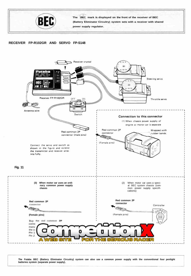
The BEC mark is displayed on the front of the receiver of BEC
(Battery Eliminator Circuitry) system sets with a receiver with shared
power supply regulator.
RECEIVER FP-R102GR AND SERVO FP-S148
Fig. 11
(3) When motor car uses an ordi-nary common power supplychassis
Red common 2Pconnector
(Female pins)
Buy the red common 2Pconnector from the kitmanufacturer and connect tothe controller.Pin 1: MinusPin 2. Plus
(2) When motor car uses a speci-al BEC system chassis (com-mon power supply specifi-cations)
Red common 2Pconnector
Connect to the red common2P connector of the control-ler.
The Futaba BEC (Battery Eliminator Circuitry) system can also use a common power supply with the conventional four penlightbatteries system (separate power supply).
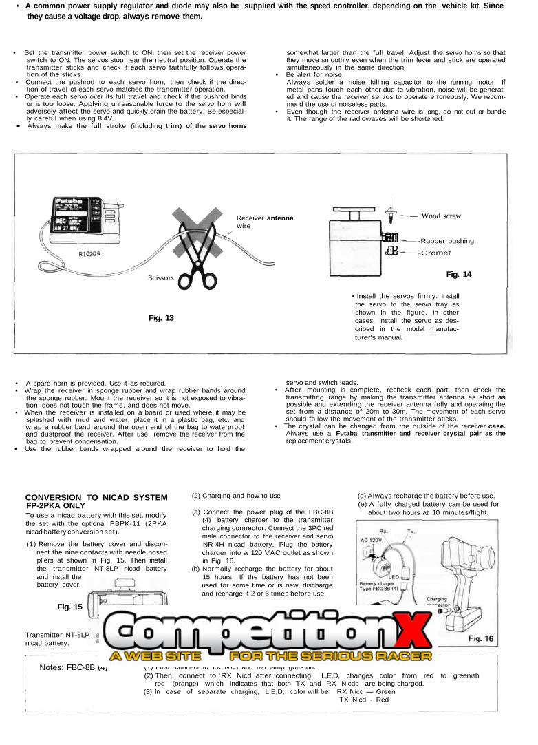
• A common power supply regulator and diode may also be supplied with the speed controller, depending on the vehicle kit. Sincethey cause a voltage drop, always remove them.
• Set the transmitter power switch to ON, then set the receiver powerswitch to ON. The servos stop near the neutral position. Operate thetransmitter sticks and check if each servo faithfully follows opera-tion of the sticks.
• Connect the pushrod to each servo horn, then check if the direc-tion of travel of each servo matches the transmitter operation.
• Operate each servo over its full travel and check if the pushrod bindsor is too loose. Applying unreasonable force to the servo horn willadversely affect the servo and quickly drain the battery. Be especial-ly careful when using 8.4V.
• Always make the full stroke (including trim) of the servo horns
somewhat larger than the full travel. Adjust the servo horns so thatthey move smoothly even when the trim lever and stick are operatedsimultaneously in the same direction.
• Be alert for noise.Always solder a noise killing capacitor to the running motor. Ifmetal pans touch each other due to vibration, noise will be generat-ed and cause the receiver servos to operate erroneously. We recom-mend the use of noiseless parts.
• Even though the receiver antenna wire is long, do not cut or bundleit. The range of the radiowaves will be shortened.
Receiver antennawire
— Wood screw
tencB
-Rubber bushing
-Gromet
Fig. 14
Fig. 13
• Install the servos firmly. Installthe servo to the servo tray asshown in the figure. In othercases, install the servo as des-cribed in the model manufac-turer's manual.
• A spare horn is provided. Use it as required.• Wrap the receiver in sponge rubber and wrap rubber bands around
the sponge rubber. Mount the receiver so it is not exposed to vibra-tion, does not touch the frame, and does not move.
• When the receiver is installed on a board or used where it may besplashed with mud and water, place it in a plastic bag, etc. andwrap a rubber band around the open end of the bag to waterproofand dustproof the receiver. After use, remove the receiver from thebag to prevent condensation.
• Use the rubber bands wrapped around the receiver to hold the
servo and switch leads.• After mounting is complete, recheck each part, then check the
transmitting range by making the transmitter antenna as short aspossible and extending the receiver antenna fully and operating theset from a distance of 20m to 30m. The movement of each servoshould follow the movement of the transmitter sticks.
• The crystal can be changed from the outside of the receiver case.Always use a Futaba transmitter and receiver crystal pair as thereplacement crystals.
CONVERSION TO NICAD SYSTEMFP-2PKA ONLYTo use a nicad battery with this set, modifythe set with the optional PBPK-11 (2PKAnicad battery conversion set).
(1) Remove the battery cover and discon-nect the nine contacts with needle nosedpliers at shown in Fig. 15. Then installthe transmitter NT-8LP nicad batteryand install thebattery cover.
Fig. 15
Transmitter NT-8LPnicad battery.
(2) Charging and how to use
(a) Connect the power plug of the FBC-8B(4) battery charger to the transmittercharging connector. Connect the 3PC redmale connector to the receiver and servoNR-4H nicad battery. Plug the batterycharger into a 120 VAC outlet as shownin Fig. 16.
(b) Normally recharge the battery for about15 hours. If the battery has not beenused for some time or is new, dischargeand recharge it 2 or 3 times before use.
(c) If the battery is left discharged for a longtime, its capacity will decrease and thelife of the battery will be shortened.After use, recharge the battery beforestoring it.
(d) Always recharge the battery before use.(e) A fully charged battery can be used for
about two hours at 10 minutes/flight.
Notes: FBC-8B (4) (1) First, connect to TX Nicd and red lamp goes on.(2) Then, connect to RX Nicd after connecting, L,E,D, changes color from red to greenish
red (orange) which indicates that both TX and RX Nicds are being charged.(3) In case of separate charging, L,E,D, color will be: RX Nicd — Green
TX Nicd - Red
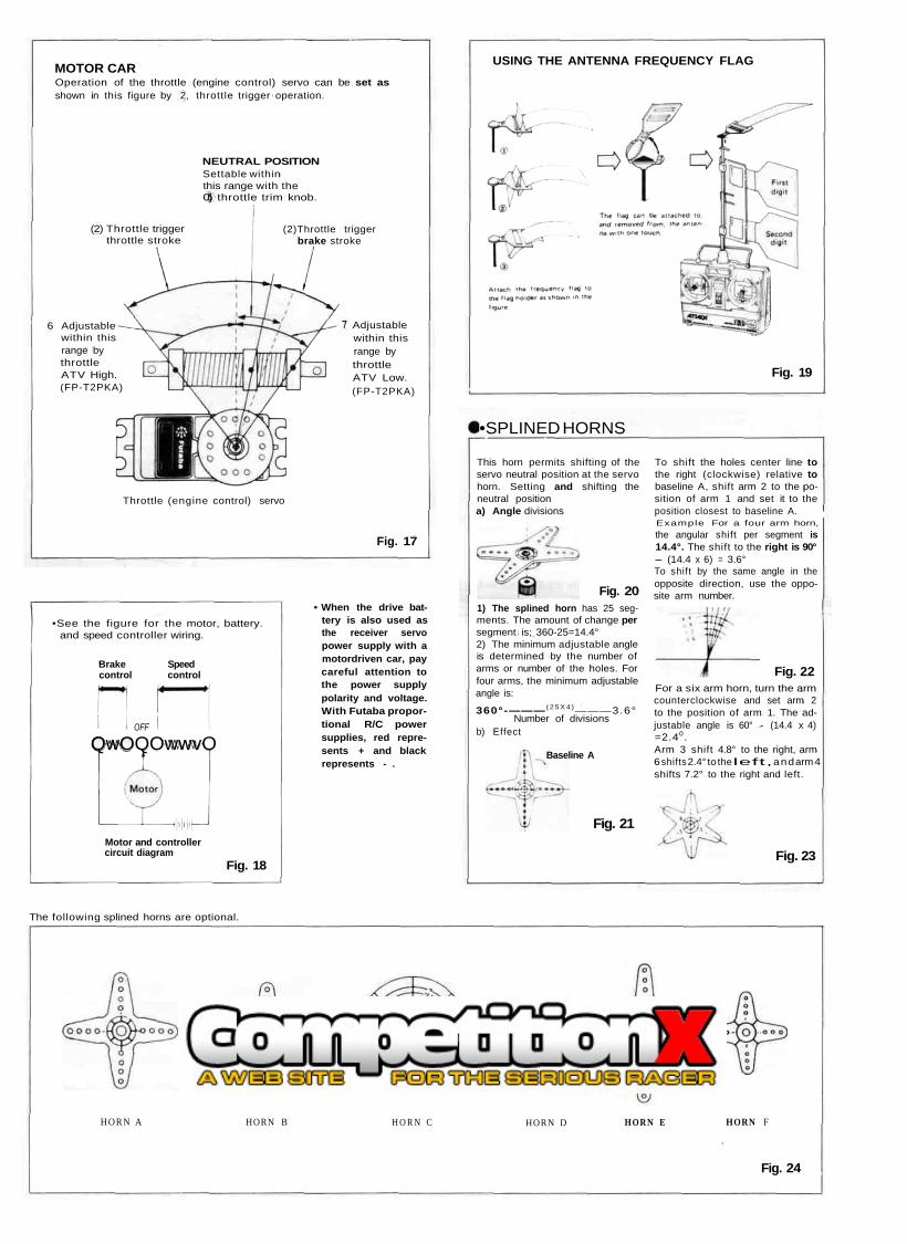
MOTOR CAROperation of the throttle (engine control) servo can be set asshown in this figure by 2, throttle trigger operation.
NEUTRAL POSITIONSettable withinthis range with the0) throttle trim knob.
(2) Throttle triggerthrottle stroke
(2)Throttle triggerbrake stroke
Adjustablewithin thisrange bythrottleATV Low.(FP-T2PKA)
Throttle (engine control) servo
• When the drive bat-tery is also used asthe receiver servopower supply with amotordriven car, paycareful attention tothe power supplypolarity and voltage.With Futaba propor-tional R/C powersupplies, red repre-sents + and blackrepresents - .
OFF
QwOQOwwvO
6 Adjustablewithin thisrange bythrottleATV High.(FP-T2PKA)
Fig. 17
•See the figure for the motor, battery.and speed controller wiring.
Brake Speedcontrol control
Motor and controllercircuit diagram
Fig. 18
USING THE ANTENNA FREQUENCY FLAG
Fig. 19
•SPLINED HORNS
This horn permits shifting of theservo neutral position at the servohorn. Setting and shifting theneutral positiona) Angle divisions
Fig. 201) The splined horn has 25 seg-ments. The amount of change persegment is; 360-25=14.4°2) The minimum adjustable angleis determined by the number ofarms or number of the holes. Forfour arms, the minimum adjustableangle is:
360°-——— ( 2 5 X 4 )———3.6°Number of divisions
b) Effect
Baseline A
To shift the holes center line tothe right (clockwise) relative tobaseline A, shift arm 2 to the po-sition of arm 1 and set it to theposition closest to baseline A.Example For a four arm horn,the angular shift per segment is14.4°. The shift to the right is 90°- (14.4 x 6) = 3.6°To shift by the same angle in theopposite direction, use the oppo-site arm number.
Fig. 21
Fig. 22For a six arm horn, turn the armcounterclockwise and set arm 2to the position of arm 1. The ad-justable angle is 60° - (14.4 x 4)=2.40.Arm 3 shift 4.8° to the right, arm6 shifts 2.4° to the left, and arm 4shifts 7.2° to the right and left.
Fig. 23
The following splined horns are optional.
HORN A HORN B H O R N C HORN D HORN E HORN F
Fig. 24
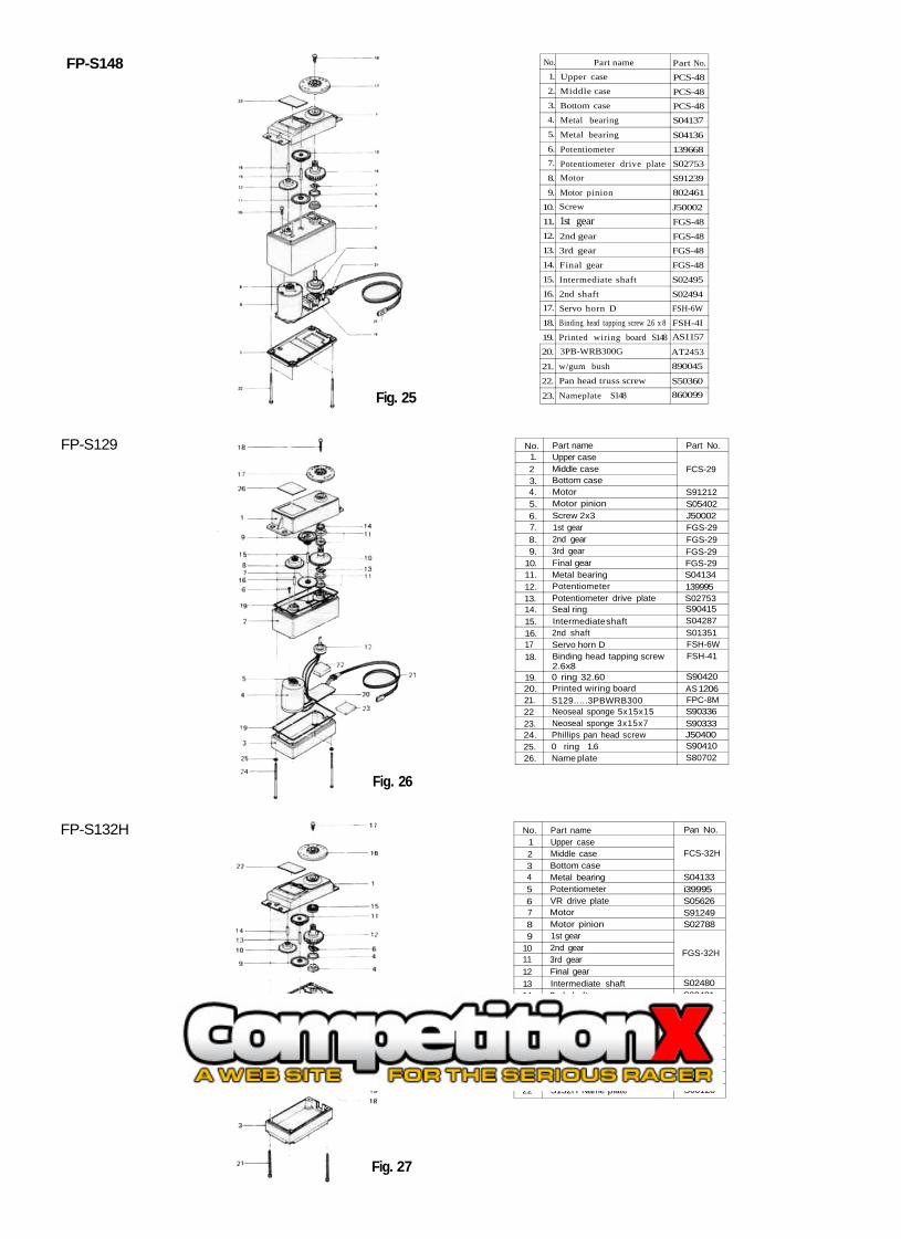
FP-S148 No.1.
2.
3.4.
5.
6.7.
8.
9.
10.
11.12.
13.
14.
15.
16.17.
18.
19.20.
21.
22.
23.
Part nameUpper case
Middle case
Bottom case
Metal bearing
Metal bearing
Potentiometer
Potentiometer drive plateMotor
Motor pinionScrew
1st gear2nd gear
3rd gear
Final gear
Intermediate shaft
2nd shaft
Servo horn D
Binding head tapping screw 2.6 x 8
Printed wiring board S1483PB-WRB300G
w/gum bush
Pan head truss screw
Nameplate S148
Part No.
PCS-48
PCS-48PCS-48S04137
S04136
139668S02753
S91239802461
J50002
FGS-48
FGS-48FGS-48
FGS-48
S02495
S02494FSH-6W
FSH-4IAS1157
AT2453890045
S50360860099Fig. 25
No.1.23.4.5.6.7.8.9.
10.11.12.13.14.15.16.1718.
19.20.21.2223.24.25.26.
Part nameUpper caseMiddle caseBottom caseMotorMotor pinionScrew 2x31st gear2nd gear3rd gearFinal gearMetal bearingPotentiometerPotentiometer drive plateSeal ringIntermediate shaft2nd shaftServo horn DBinding head tapping screw2.6x80 ring 32.60Printed wiring boardS129.....3PBWRB300Neoseal sponge 5x15x15Neoseal sponge 3x15x7Phillips pan head screw0 ring 1.6Name plate
Part No.
FCS-29
S91212S05402J50002FGS-29FGS-29FGS-29FGS-29S04134139995S02753S90415S04287S01351FSH-6WFSH-41
S90420AS 1206FPC-8MS90336S90333J50400S90410S80702
FP-S129
Fig. 26
No.123456789
10111213141516171819202122
Part nameUpper caseMiddle caseBottom caseMetal bearingPotentiometerVR drive plateMotorMotor pinion1st gear2nd gear3rd gearFinal gearIntermediate shaft2nd shaftBall bearingServo horn 0Horn mounting screwS132H Printed wiring boardS132H 3PBWRB-300Lead wire packingCase mounting screwS132H Name plate
Pan No.
FCS-32H
S04133i39995S05626S91249S02788
FGS-32H
S02480S02481S04130FSH 6WFSH-41AS1271FPC-8MS90045J50082S60128
FP-S132H
Fig. 27
GUARANTEE
Your NEW FUTABA Digital Proportional R/C system is guaranteed against defects inworkmanship and material for 180 days from the date of purchase when the attachedregistration card is returned to us within ten days of purchase.
This Guarantee is null and void if the R/C system has been improperly handled, damagedin a crash, or tampered with and does not cover the replacement of plastic housings orelectronic components damaged due to the use of improper voltages.
When service is required, please take your equipment to your local authorized servicestation or ship it directly to us. All postage, shipping, and insurance charges must be paidby the user.
REPAIR SERVICE
• When requesting repair of trouble that has occurred suddenly of from long use, de-scribe the trouble symptoms in as much detail as possible.This will facilitate detection of the trouble point and shorten the repair period greatly.
• Defects caused by faulty materials of workmanship will be corrected free of charge.
• This limited warranty is null and void if the set has been tampered with or dis-assembled.Refer to warranty statement for details.
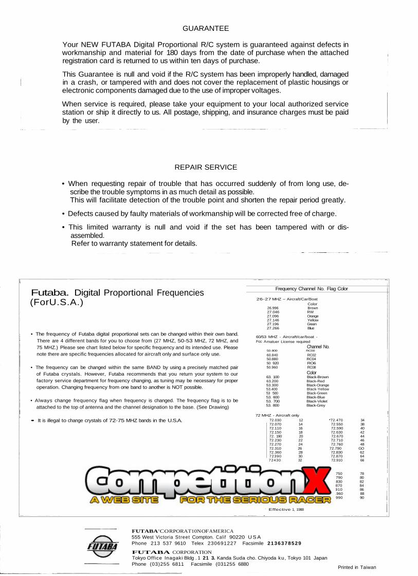
Futaba. Digital Proportional Frequencies(For U.S.A.)
26.996 Brown27.046 RW27.096 Orange27.146 Yellow27.196 Green27.266 Blue
• The frequency of Futaba digital proportional sets can be changed within their own band.There are 4 different bands for you to choose from (27 MHZ, 50-53 MHZ, 72 MHZ, and75 MHZ.) Please see chart listed below for specific frequency and its intended use. Pleasenote there are specific frequencies allocated for aircraft only and surface only use.
50.880 RC0450 920 RO6
• The frequency can be changed within the same BAND by using a precisely matched pairof Futaba crystals. However, Futaba recommends that you return your system to ourfactory service department for frequency changing, as tuning may be necessary for properoperation. Changing frequency from one band to another is NOT possible.
53 500 Black-Green
• Always change frequency flag when frequency is changed. The frequency flag is to beattached to the top of antenna and the channel designation to the base. (See Drawing)
72 MHZ - Aircraft only• It is illegal to change crystals of 72-75 MHZ bands in the U.S.A.
75 MHZ - Car/Boat only
• 75.630 72 • 76.960 88
26-27 MHZ - Aircraft/Car/BoatColor
60/53 MHZ - Aircraft/car/boat -Fcc A
60.840 RC02
50.960 RC08Color
63. 100 Black-Brown63.200 Black-Red53.300 Black-Orange53.400 Black-Yellow
53. 600 Black-Blue53. 700 Black-Violet53. 800 Black-Grey
Frequency Channel No. Flag Color
matuer License requiredChannel No.
50.800 RC00
72.030 12 *72.470 3472.070 14 72.550 3872.110 16 72.590 4072.150 18 72.630 4272. 190 20 72.670 4472.230 22 72.710 4672.270 24 72.760 4872.310 26 72.790 GO72.360 28 72.830 6272390 30 72.870 6472430 32 72.910 66
76.430 62 75.750 7876.470 64 76.790 8076.610 66 76.830 8276.650 68 76.870 8476.690 70 *75.910 86
76.670 74 *76.990 9076.710 76
Effective 1, 1988
FUTABA ' CO RPORAT10N OF AMERICA555 West Victoria Street Compton. Calif 90220 U S APhone 213 537 9610 Telex 230691227 Facsimile 2136378529
FUTABA CORPORATIONTokyo Office Inagaki BIdg . 1 21 3. Kanda Suda cho. Chiyoda ku, Tokyo 101 JapanPhone (03)255 6811 Facsimile (031255 6880
Printed in Taiwan