Embed Size (px)
Citation preview

Purdue UniversityPurdue e-Pubs
Open Access Theses Theses and Dissertations
4-2016
Failure pressure and fatigue analysis of the API 12Fshop welded, flat bottom tanksAndres E. Rondon AnduezaPurdue University
Follow this and additional works at: https://docs.lib.purdue.edu/open_access_theses
Part of the Civil Engineering Commons
This document has been made available through Purdue e-Pubs, a service of the Purdue University Libraries. Please contact [email protected] foradditional information.
Recommended CitationRondon Andueza, Andres E., "Failure pressure and fatigue analysis of the API 12F shop welded, flat bottom tanks" (2016). Open AccessTheses. 811.https://docs.lib.purdue.edu/open_access_theses/811
Graduate School Form30 Updated
PURDUE UNIVERSITYGRADUATE SCHOOL
Thesis/Dissertation Acceptance
This is to certify that the thesis/dissertation prepared
By
Entitled
For the degree of
Is approved by the final examining committee:
To the best of my knowledge and as understood by the student in the Thesis/Dissertation Agreement, Publication Delay, and Certification Disclaimer (Graduate School Form 32), this thesis/dissertation adheres to the provisions of Purdue University’s “Policy of Integrity in Research” and the use of copyright material.
Approved by Major Professor(s):
Approved by:Head of the Departmental Graduate Program Date
ANDRES EDUARDO RONDON ANDUEZA
FAILURE PRESSURE AND FATIGUE ANALYSIS OF THE API 12F SHOP WELDED, FLAT BOTTOM TANKS
Master of Science in Civil Engineering
Sukru GuzeyCo-chair
Mark Bowman Co-chair
Ghadir Haikal
Sukru Guzey
Dulcy Abraham 04/20/2016

i
i
FAILURE PRESSURE AND FATIGUE ANALYSIS OF THE API 12F SHOP
WELDED, FLAT BOTTOM TANKS
A Thesis
Submitted to the Faculty
of
Purdue University
by
Andres E Rondon Andueza
In Partial Fulfillment of the
Requirements for the Degree
of
Master of Science in Civil Engineering
May 2016
Purdue University
West Lafayette, Indiana
ii
ii
To my beloved wife
Gisela
To my mother
Carmen
For all the love and support they have given me throughout all these years.

iii
iii
ACKNOWLEDGEMENTS
I would like to express my sincere gratitude to my advisor Professor Sukru Guzey for his
invaluable support, advice, and friendship throughout the development of this project. My
research would not have been possible without his guidance and motivation
I would also like to thank my examination committee members, Professor Mark
Bowman, and Professor Ghadir Haikal for serving on my defense committee and for their
support and advice throughout my time at Purdue.
Additionally, I would like to gratefully acknowledge the support from the American
Petroleum Institute, Committee on Refinery Equipment, Subcommittee on Aboveground
Storage Tanks, Work Group on 12 Series documents, and Task Group on 12F Pressure
Research Project. I would also like thank to George Morovich, Mark Baker, David Nadel,
Philip Myers, Kieran Claffey, and Nathaniel Wall for fruitful discussion and support
throughout the study.

iv
iv
TABLE OF CONTENTS
Page
LIST OF TABLES ............................................................................................................. vi
LIST OF FIGURES ......................................................................................................... viii
ABSTRACT ........................................................................................................................ x
CHAPTER 1. INTRODUCTION .................................................................................... 1
1.1 Thesis Background .................................................................................................... 1
1.2 Objective and Scope .................................................................................................. 2
1.3 Organization .............................................................................................................. 2
CHAPTER 2. FAILURE PRESSURE OF THE API 12F STORAGE TANKS .............. 4
2.1 Introduction ............................................................................................................... 4
2.2 Background Information ........................................................................................... 5
2.2.1 API 12F Specification for Shop Welded Tanks for Storage of Production
Liquids [1] ....................................................................................................... 5
2.2.2 API 937 Evaluation of Design Criteria for Storage Tanks with Frangible Roof
Joints [5] .......................................................................................................... 8
2.3 Methodology ........................................................................................................... 11
2.3.1 Elastic Stress Analysis ................................................................................... 17
2.3.2 Elastic Buckling Mode Analysis ................................................................... 18
2.3.3 Elastic-Plastic Stress Analysis ....................................................................... 19
2.3.4 Wind Load Analysis ...................................................................................... 21
2.4 Analysis and Discussion .......................................................................................... 22
2.5 Conclusions ............................................................................................................. 38
CHAPTER 3. FATIGUE ANALYSIS OF THE API 12F TANKS ............................... 41
3.1 Introduction ............................................................................................................. 41

v
v
Page
3.2 Background Information ......................................................................................... 42
3.2.1 API 12F Specification for Shop Welded Tanks for Storage of Production
Liquids [1] ..................................................................................................... 42
3.2.2 ASME Boiler and Pressure Vessel Code. Section VIII. Division 2 [15] ...... 45
3.3 Computational Models ............................................................................................ 48
3.4 Fatigue Evaluation - Elastic Stress Analysis ........................................................... 54
3.5 Conclusions ............................................................................................................. 63
CHAPTER 4. CONCLUSION ....................................................................................... 65
4.1 Failure Pressure of the API 12F Storage Tanks ...................................................... 65
4.2 Fatigue Analysis of the API 12F Tanks .................................................................. 66
LIST OF REFERENCES .................................................................................................. 67

vi
vi
LIST OF TABLES
Table .............................................................................................................................. Page
1. Tank Dimensions ....................................................................................................... 8
2. Summary of FE cases and subcases ......................................................................... 16
3. Additional tank dimensions. .................................................................................... 17
4. Summary of yielding and buckling pressures for tanks with diameters from
7ft. 11in. (2.4 m) to 11ft (3.4 m). ............................................................................. 23
5. Summary of yielding and buckling pressures for tanks with 12 ft. (3.7 m) diameter
.................................................................................................................................. 23
6. Summary of yielding and buckling pressures for tanks with 15 ft. 6 in. (4.7 m)
diameter.................................................................................................................... 24
7. Summary of yielding and buckling pressures for tank with 21 ft. 6 in. (6.6 m)
diameter.................................................................................................................... 24
8. Uplift and stresses occurring at the shell-to-bottom joint due to a 24 oz./in²
(10.3 kPa) pressure - Shell thickness 3/16 in (4.8 mm). SCL1: Highest membrane
stress at bottom joint. SCL2: Highest membrane plus bending stress at bottom joint
.................................................................................................................................. 30
9. Uplift and stresses occurring at the shell-to-bottom joint due to a 24 oz./in² (10 kPa)
pressure - Shell thickness 1/4 in (6.4 mm). SCL1: Highest membrane stress at
bottom joint. SCL2: Highest membrane plus bending stress at bottom joint .......... 31

vii
vii
Table .............................................................................................................................. Page
10. Results of the wind load analysis for the of the 12 ft. (3.7 m) diameter and 25 ft.
(7.6 m) high shop-welded tank ................................................................................ 37
11. Tank Dimensions ..................................................................................................... 45
12. Summary of pressure cycles and thicknesses in the tank models. ........................... 53
13. Number of permissible cycles at the top and bottom joints of API 12F shop welded
tanks ......................................................................................................................... 60
14. Number of allowable pressure cycles at clean-out joints of API 12F shop welded
flat bottom tanks ...................................................................................................... 61

viii
viii
LIST OF FIGURES
Figure ............................................................................................................................. Page
1. Typical shop-welded, flat-bottom, storage tank with proposed semicircular
top clean out .................................................................................................................. 6
2. Typical roof-to-shell joint. .......................................................................................... 11
3. Typical API 12F finite element tank model. ............................................................... 12
4. Typical rafter configuration. ....................................................................................... 13
5. Top and bottom welded joints. .................................................................................... 14
6. Stress-strain curve of mild steel material .................................................................... 20
7. Wind pressure distribution over the shell ................................................................... 21
8. Springs distribution on the tank bottom ...................................................................... 21
9. Effect of the tank height in the top joint yielding ....................................................... 25
10. Effect of the tank height in the top joint yielding ....................................................... 26
11. Relative Strength Ratio (shell-to-bottom strength / roof-to-shell strength) for
tanks with 3/16 in. (4.8 mm) shell thickness .............................................................. 27
12. Relative Strength Ratio (shell-to-bottom strength / roof-to-shell strength) for
tanks with 1/4 in. (6.4 mm) shell thickness ................................................................ 28
13. Critical Yielding Pressure occurring at the top or bottom joints, uplift pressure
obtained through FEA, and failure and uplift pressures computed by hand calculations
using API 937 formulation. Tanks with 3/16 in. (4.8 mm) shell thickness ................ 28

ix
ix
Figure ............................................................................................................................. Page
14. Critical Yielding Pressure occurring at the top or bottom joints, uplift pressure
obtained through FEA, and failure and uplift pressures computed by hand calculations
using API 937 formulation. Tanks with 1/4 in. (6.4 mm) shell thickness .................. 29
15. Buckling pressure vs roof-to-shell yielding pressure.................................................. 32
16. Typical roof-to-shell joint and shell-to-bottom joint buckling modes ........................ 33
17. Typical tank model subjected to internal pressure until rupture or plastic collapse ... 33
18. Typical Internal Pressure-Strain Curve ....................................................................... 34
19. Average rupture-to-yielding ratios for tanks with 3/16 in. (4.8 mm) shell thickness. 35
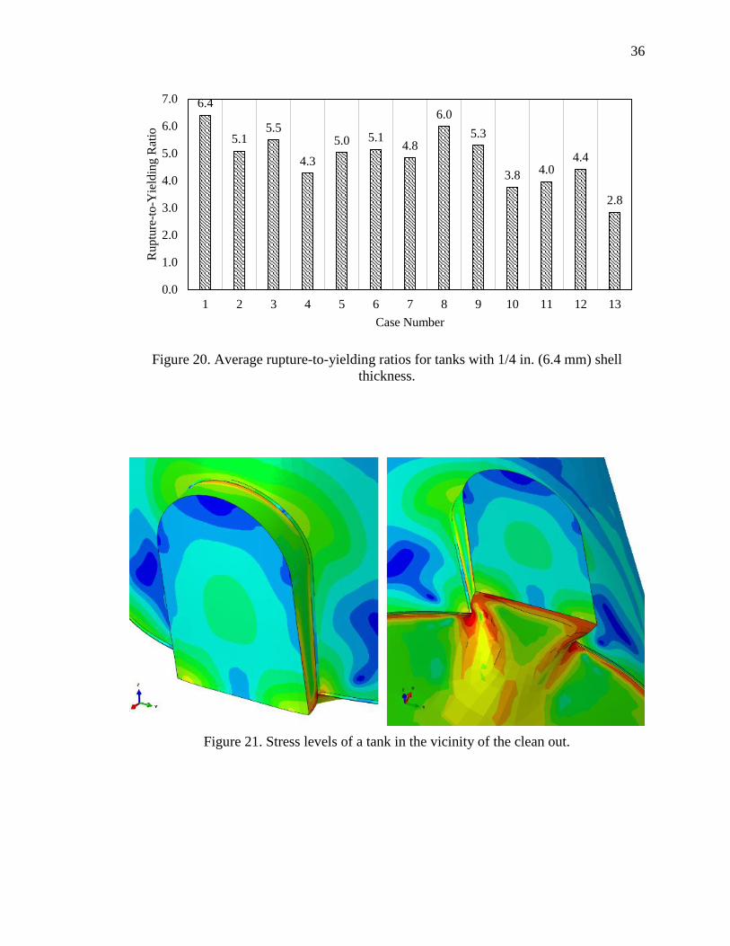
20. Average rupture-to-yielding ratios for tanks with 1/4 in. (6.4 mm) shell thickness. .. 36
21. Stress levels of a tank in the vicinity of the clean out. ................................................ 36
22. Scaled deformation and stress levels due to wind pressure. ....................................... 37
23. Typical shop-welded, flat-bottom, storage tank with proposed semicircular
top clean out ................................................................................................................ 44
24. Typical API 12F finite element tank 3D model. ......................................................... 50
25. Typical welded joints of the API 12F axisymmetric tank models .............................. 51
26. Typical submodel of the intersection between the clean-out and the tank bottom. .... 52
27. Stress Classification Lines .......................................................................................... 55
28. Typical stress classification for a cross section .......................................................... 57
29. Smooth bar design fatigue curve for Carbon, Low Alloy, Series 4xx, and High
Tensile Strength Steels for temperatures not exceeding 371°C (700°F) where
𝜎𝑢𝑡𝑠 ≤ 80 Ksi (552 MPa) ............................................................................................ 58
30. Minimum number of cycles for each API 12F tank and location of the most
critical joint. ................................................................................................................ 62

x
x
ABSTRACT
Rondon Andueza, Andres E M.S.C.E., Purdue University, May 2016. Failure Pressure and
Fatigue Analysis of the API 12F Shop Welded, Flat Bottom Tanks.
Major Professor: Sukru Guzey.
This study investigates the failure pressure on the API 12F shop welded steel tanks and
performs a fatigue evaluation to estimate the permissible number of pressure cycles for
these equipment. Four different analyses were carried out on more than 350 finite element
models to determine various failure pressure modes of these storage tanks. An elastic
analysis considering potential buckling modes was developed to determine the yielding
pressure of the tanks. The redistribution of stresses due to inelastic deformations and plastic
collapse were evaluated through an elastic-plastic stress analysis considering the plastic
hardening of the material. A wind load analysis was performed to evaluate the stress levels
at all regions of the tank and estimate the uplift deformations. Moreover, the increase of
the design pressure was investigated regarding the stress levels and bottom uplift.
Additionally, an elastic stress analysis following the ASME Boiler & Pressure Vessel Code
Section VIII, Division 2, Design-by-Analysis rules was implemented to determine the
fatigue life of the storage tanks. This research provides engineering calculations to evaluate
the current design of the API 12F tanks and the design internal pressures guaranteeing a
safe performance of the equipment.

1
1
CHAPTER 1. INTRODUCTION
1.1 Thesis Background
The API specification 12F is intended to provide material, design, fabrication, and testing
requirements for a list of standard shop-built, flat bottom steel storage tanks. These tanks
are often used in the exploration and production phases of the oil and gas industry and they
are fabricated, completely furnished in accordance to the need of the purchaser, and
shipped ready for installation in the field.
The motivation of this research is to investigate the behavior of shop-welded tanks under
different load cases. The American Petroleum Institute, Committee on Refinery Equipment,
Subcommittee on Aboveground Storage Tanks (API SCAST) identified the need to
determine the failure modes for tanks built to API 12F. Thus, API 12F Flat Bottom Tanks
Failure Pressure Study (Phase 1) was developed under the API Contract #2015-109646 and
presented the research findings in the report #15G06-01 dated November 11, 2015 as well
as submitted as a technical paper in the Thin-Walled Structures journal.
The analysis and results obtained in Phase 1 of the mentioned study are summarized in
Chapter 2 of this thesis. Based on the conclusions of Phase 1, API SCAST identified the
need to further investigate the API 12F Flat Bottom Tanks to determine the fatigue life and
perform brittle fracture evaluation of the subject tanks by using established fatigue and
fracture mechanics principles.

2
2
The fatigue analysis and estimation of allowable pressure cycles of each tank are presented
in Chapter 3. The brittle fracture evaluation is not part of the scope of this thesis.
1.2 Objective and Scope
The objective of this study is to determine the various failure pressure modes for shop-
welded flat-bottom tanks for oilfield production liquids. Moreover, this investigation aims
to perform a fatigue analysis to estimate the minimum number of pressure cycles for each
API 12F storage tank.
The scope of the study included: (a) an elastic stress analysis to determine the yielding
pressure of the steel tanks, evaluate the relative strength ratio between the roof-to-shell and
bottom-to-shell joints, and investigate stress levels and uplift deformations due to the
design internal pressure, (b) an elastic buckling mode analysis to estimate potential
buckling modes of the tanks, (c) an elastic-plastic stress analysis considering the plastic
hardening of the material and non-linear deformations to determine the plastic collapse of
the tanks, (d) a wind load analysis on the API 12F shop-welded tank with the greatest
height-diameter ratio to show the stress levels at all regions of the tank and uplift
deformation, (e) a fatigue analysis to estimate the allowable number of pressure cycles
caused by different loading conditions.
1.3 Organization
The thesis contains four chapters. The layout presented in this thesis is as follows:
Chapter 1: background information, objective and scope.
Chapter 2: reviews the investigation developed to evaluate the failure pressure modes of
the API 12F shop-welded flat bottom tanks.

3
3
Chapter 3: describes the methodology and results of the fatigue evaluation to determine
the number of permissible cycles for each steel tank studied.
Chapter 4: summarizes the findings and conclusions presented in this research.

4
4
CHAPTER 2. FAILURE PRESSURE OF THE API 12F STORAGE TANKS
2.1 Introduction
API 12F tanks are used for the storage of petroleum production liquids in the upstream,
exploration, and production segment of the oil and gas industry. They are shop-fabricated
and furnished by the manufacturer ready for the installation. The API 12F specification
sets the minimum requirements for material, design, fabrication, and inspection of shop-
welded tanks for oilfield production liquids 0. This specification is intended to provide a
list of recommended tanks with dimensions and internal pressure capacities for the
convenience of purchasers. Moreover, the minimum metal thickness and permissible
design pressure suggested by the API 12F are determined to provide tanks of adequate
safety and economy.
Failure of aboveground storage tanks can be environmentally threatening and lead to a
significant cost impact [2]-[3]. Therefore, engineering calculations in compliance with
industry standards and codes have been developed to ensure safe and reliable equipment
and designs. Recently, the oil and gas industry identified the need to further investigate the
failure pressure modes of the API 12F shop-welded tanks. The purpose of this investigation
is to improve the operation performance and evaluate the pressure limits of these tanks.
Furthermore, the results of this research is of the interest of tank designers, manufacturers,
and purchasers.

5
The main objective of this study is to develop a stress analysis using finite element models
(FEM) to determine the failure pressure on the eleven current API 12F flat bottom tank
sizes as well as two proposed new sizes. Since a critical tank problem occurs when the
shell-to-bottom joint fails before the roof-to-shell joint [4] and some uncertainty exists
regarding the relative strength between both joints [5], the present research evaluates the
capacity of the API 12F tanks considering the yielding strength, buckling strength and
plastic deformations of the shell-to-bottom and roof-to-shell joint in order to clarify
unresolved issues.
The following section provides background information regarding the publications and
specifications used for the development of the present study. The mentioned works were
used as reference for the construction of the computational models as well as for the
validation of the results obtained in the analyses.
2.2 Background Information
2.2.1 API 12F Specification for Shop Welded Tanks for Storage of Production
Liquids 0
This specification presents the requirements for shop-welded tanks and provides the oil
and gas industry with a series of safe and reasonably economic tanks for the convenience
of the manufacturers and purchasers. Moreover, tanks covered in API 12F have been
accordingly calculated to assure structural stability and safety while using the minimum
metal thickness, welding, and bolting specifications for each size.
API 12F tanks consist of shop-fabricated vertical, cylindrical, aboveground, closed top,
welded steel storage tanks, and they are completely fabricated and furnished according to

6
various standard sizes and capacities for internal pressures stipulated in the specification.
The tank bottom shall be flat (Type A) or conical (Type B) while the roof deck shall be
self-supported, cone type, with a slope of 1 in. (25.4 mm) in 1 ft. (0.3 m). Diameters of the
tanks range from 7 ft. 11 in. (2.4 m) to 15 ft. 6 in (4.7 m), and the heights vary from 8 ft.
(4.7 m) to 24 ft. (7.3 m). The working capacity of the tanks range from 72 bbl. (11.4 m3)
to 746 bbl. (118.6 m3). It can be noted that the dimensions are not particularly large since
the purpose of these tanks is to be built in the shop of the manufacturer, transported, and
delivered ready for installation in the field.
Figure 1. Typical shop-welded, flat-bottom, storage tank with proposed semicircular top
clean-out

7
The materials listed in the specification were selected to provide sufficient strength and
reasonable service life. However, if the manufacturer, in agreement with the purchaser,
decides to fabricate tanks with higher strength materials, the minimum thickness stipulated
in the API 12F shall not be reduced. The thickness of the bottom plates shall be either 1/4 in.
(6.4 mm) or 3/8 in. (9.5 mm). Moreover, the thickness of the shell and roof plates shall be
the same (3/16 in. (4.8 mm) or 1/4 in (6.4 mm)), except for 15 ft. 6 in. (4.7 m) and larger
diameters tanks where the roof shall be 1/4 in. (6.4 mm) nominal unless rafters are provided.
Additionally, API 12F tanks shall be furnished with a 36 in. (0.9 m) by 24 in. (0.6 m)
extended-neck cleanout. A new 36 in. (0.9 m) high by 24 in. (0.6 m) wide rectangular and
semicircular top clean out design has been proposed to avoid local stress concentrations in
the proximity of this opening. Typical API 12F shop welded tanks for storage of production
liquids with the proposed clean out design is shown in Figure 1.
Table 1 summarizes the standard dimensions and establishes the maximum internal design
pressure and vacuum of the eleven current API 12F shop-welded tanks. The limit pressures
were obtained from engineering calculations following the minimum metal thickness and
bolting specifications for each tank filled with water 0. In addition, the American Petroleum
Institute (API) has evaluated to include two new tank sizes: 21 ft. 6 in. (6.6 m) diameter by
16 ft. (4.9 m) high and 15 ft. 6 in. (4.7 m) diameter by 30 ft. (9.1 m) high.

8
Table 1. Tank Dimensions
Nominal
Capacity
Design Pressure
oz./in² (kPa)
Approximate
Working
Capacity
Outside
Diameter Height
bbl., m3 Pressure,
Vacuum bbl., m3 ft-in. (m) ft., m
90, 14.3 16, ½ (6.9, 0.2) 72, 11.4 7-11 (2.4) 10, 3.0
100, 15.9 16, ½ (6.9, 0.2) 79, 12.6 9-6 (2.9) 8, 2.4
150, 23.8 16, ½ (6.9, 0.2) 129, 20.5 9-6 (2.9) 12, 3.7
200, 31.8 16, ½ (6.9, 0.2) 166, 26.4 12 (3.7) 10, 3.0
210, 33.4 16, ½ (6.9, 0.2) 200, 31.8 10 (3.0) 15, 4.6
250, 39.7 16, ½ (6.9, 0.2) 224,35.6 11 (3.4) 15, 4.6
300, 47.7 16, ½ (6.9, 0.2) 266, 42.3 12 (3.7) 15, 4.6
400, 63.6 16, ½ (6.9, 0.2) 366, 58.2 12 (3.7) 20, 6.1
500, 79.5 16, ½ (6.9, 0.2) 466, 74.1 12 (3.7) 25, 7.6
500,79.5 8, ½ (3.5, 0.2) 479, 76.2 15-6 (4.7) 16, 4.9
750,119.2 8, ½ (3.5, 0.2) 746, 118.6 15-6 (4.7) 24, 7.3
2.2.2 API 937 Evaluation of Design Criteria for Storage Tanks with Frangible Roof
Joints [5]
The design procedures and performance of aboveground storage tanks have been
influenced by unexpected failures that led to tragic environmental impacts and substantial
loss of capital. One of the most undesirable failure modes is the loss of the shell-to-bottom
joint of the tank, which not only affects the tank’s operation but also can produce major
leaks of the content into the ground [6]. Storage tanks with frangible roof joints are
designed considering that the roof-to-shell joint will fail before the shell-to-bottom joint in
case of excessive internal pressure. The API 650 [7] standard provides the calculation rules
for frangible roof tanks and has been a reference of the design of welded tanks for oil
storage since it was first published in 1961.
9
Swenson et al. [8] evaluated the design procedures for frangible roof tanks stated in the
API 650, and provided new insights to guarantee the appropriate roof-to-shell joint
behavior. The work presented by Swenson was summarized and compiled into the API 937
publication, “Evaluation of Design Criteria for Storage Tanks with Frangible Roof Joints”.
This publication derived the API 650 design formulation for frangible roofs and compared
the failure pressures calculated using these equations with results obtained from the
analysis of finite element tank models. Moreover, API 937 concluded that the pressures
reported in accordance with the API 650 are significantly lower than the ones computed
from the FEA. Additionally, the uplift pressures were calculated using the API 650 rules
and FEA, and in this case the results were similar.
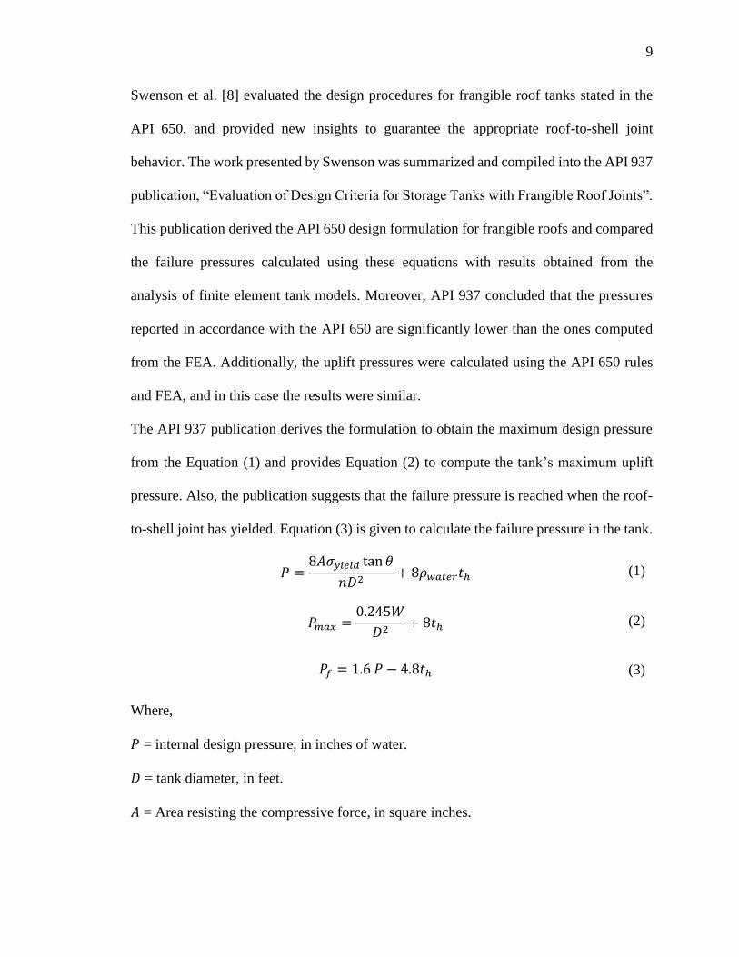
The API 937 publication derives the formulation to obtain the maximum design pressure
from the Equation (1) and provides Equation (2) to compute the tank’s maximum uplift
pressure. Also, the publication suggests that the failure pressure is reached when the roof-
to-shell joint has yielded. Equation (3) is given to calculate the failure pressure in the tank.
𝑃 =8𝐴𝜎𝑦𝑖𝑒𝑙𝑑 tan 𝜃
𝑛𝐷2+ 8𝜌𝑤𝑎𝑡𝑒𝑟𝑡ℎ (1)
𝑃𝑚𝑎𝑥 =0.245𝑊
𝐷2+ 8𝑡ℎ (2)
𝑃𝑓 = 1.6 𝑃 − 4.8𝑡ℎ (3)
Where,
𝑃 = internal design pressure, in inches of water.
𝐷 = tank diameter, in feet.
𝐴 = Area resisting the compressive force, in square inches.

10
𝜎𝑦𝑖𝑒𝑙𝑑 = Compressive yield strength, in pounds per square foot.
𝜃 = Angle between the roof and a horizontal plane at the roof-to-shell junction, in degrees.
𝑛 = 1.6. Safety factor
𝜌𝑤𝑎𝑡𝑒𝑟 = Density of water, in pounds per cubic foot.
𝑡ℎ = nominal roof thickness, in inches.
𝑃𝑚𝑎𝑥 = maximum design pressure, limited by uplift
𝑊 = Total weight of the shell and any framing (but not roof plates) supported by the shell
and roof, in pounds,
𝑃𝑓 = calculated failure pressure, in inches of water.
1 inch of water = 0.03606 psi
Since the failure mechanism of the tanks with frangible roof joints establishes that the roof-
to-shell joint shall fail prior the shell-to-bottom joint, the cross-sectional area of the roof-
to-shell joint is limited by Equation (4). For the purpose of this investigation, the cross-
sectional area of the roof-to-shell joint was estimated using Figure 2.
𝐴 =𝑊
2𝜋 𝜎𝑦𝑖𝑒𝑙𝑑 tan 𝜃 (4)
The relative strength between the roof-to-shell joint and the shell-to-bottom joint was
investigated by Swenson et al. [8]. It was suggested that the liquid level is an important
parameter to consider in the failure of tanks due to overpressurization. Swenson identified
that the liquid pressure over the bottom of the tank relieves the stresses at that juncture.
However, especially for small empty tanks or those with low liquid level, the ratio between
the top-yielding pressure and the bottom-yielding pressure is not significant, leading the
design to have a small safety factor. Moreover, API 937 suggests that the liquid level to be
11
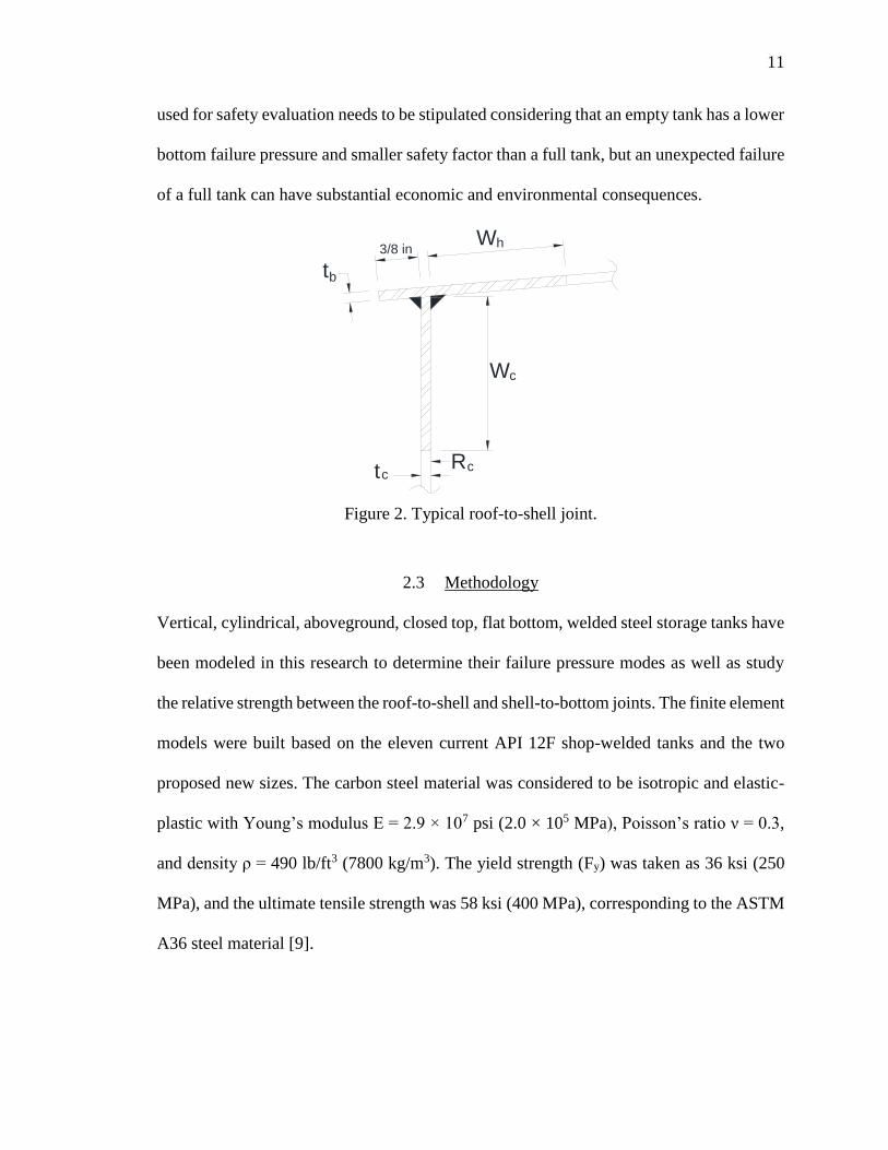
used for safety evaluation needs to be stipulated considering that an empty tank has a lower
bottom failure pressure and smaller safety factor than a full tank, but an unexpected failure
of a full tank can have substantial economic and environmental consequences.
Figure 2. Typical roof-to-shell joint.
2.3 Methodology
Vertical, cylindrical, aboveground, closed top, flat bottom, welded steel storage tanks have
been modeled in this research to determine their failure pressure modes as well as study
the relative strength between the roof-to-shell and shell-to-bottom joints. The finite element
models were built based on the eleven current API 12F shop-welded tanks and the two
proposed new sizes. The carbon steel material was considered to be isotropic and elastic-
plastic with Young’s modulus E = 2.9 × 10⁷ psi (2.0 × 10⁵ MPa), Poisson’s ratio ν = 0.3,
and density ρ = 490 lb/ft3 (7800 kg/m3). The yield strength (Fy) was taken as 36 ksi (250
MPa), and the ultimate tensile strength was 58 ksi (400 MPa), corresponding to the ASTM
A36 steel material [9].
3/8 in
t
Wh
W
R
c
b
tcc
12
The finite element software ABAQUS version 6.13 [10] was used in this study to perform
the stress analysis and determine the failure pressures. Since this research required several
FE tank models, quadrilateral shell elements S4R were used to optimize the number of
nodes in the simulations and reduce computational time. S4R elements are four-node,
doubly curved elements with hourglass control, finite membrane strain, and reduced
integration formulation. The mesh size on each tank gradually varies from the center of the
shell to the roof and bottom junctures, being coarse in the middle and much finer near the
joints. A convergence analysis was performed to evaluate the stresses in the proximity of
the welded joints and discard any stress singularity in the computational models. After
several iterations and mesh refinements, the convergence of results were verified along the
top and bottom joints of the tanks. A typical finite element model is shown in Figure 3.
Figure 3. Typical API 12F finite element tank model.

13
In accordance with the API 12F specification, the flat bottom plate thicknesses used were
1/4 in. (6.4 mm) and 3/8 in. (9.5 mm). Also, the thickness of the cylindrical shell plates
were 3/16 in. (4.8 mm) and 1/4 in. (6.4 mm) The roof design was cone-type with a slope
of 1 in. (25.4 mm) in 1 ft. (0.3 m), and the plate thicknesses were the same as the shell
plates. Additional structural supports in the form of rafters were included in the larger
diameter tank models when 3/16 in. (4.8 mm) thick roof plates were used. The models
assumed that the rafters were welded to the cylindrical shell and supported by a center
column. Moreover, the roof deck was not attached to the rafters. Eight and ten C6x8.2
beam shapes were used for the 15 ft. 6 in. (4.7 m) and 21 ft. 6 in. (6.6 m) diameter tanks,
respectively, and a 6 in. (150 mm) standard pipe was assigned to the central column. The
center ring plate had a thickness of 1/4 in. (6.4 mm). A typical rafter configuration can be
observed in Figure 4.
Figure 4. Typical rafter configuration.

14
The flat bottom and the tank roof had a chime projection of 3/8 in. (9.5 mm) measured
from the outer surface of the shell. The non-flanged shell-to-bottom joint included full-
fillet welds on the inside and outside surfaces of the tank’s shell, and the roof-to-shell was
welded with a maximum 3/16 in. (4.8 mm) continuous fillet weld. The computational
models of the welded joints were built following the methodology presented by Niemi et
al. [11] as shown in Figure 5. A 36 in. (0.9 m) high by 24 in. (0.6 m) wide rectangular and
semicircular top clean-out was modeled as shown in Figure 1. The tank models show the
local stress concentrations in the proximity of this openings. Table 2 summarizes the FE
cases and subcases developed in this research and provides geometric information of each
model.
Figure 5. Top and bottom welded joints.
Since the models shall be capable of estimating the bottom uplift at specific pressures,
linear elastic springs acting along the vertical Z direction were attached to the tank bottom
elements to simulate the soil interaction with the tank. Only compression springs were
considered in the analysis. Thus, after applying the liquid and internal pressure as well as
Roof
Shell
Shell
Fillet Weld
Full-Fillet Weld
Bottom
SCL 1
SCL 2

15
the self-weight, those springs in tension were removed from the models. Furthermore, the
analysis considered that the unanchored tanks were placed over a compacted sand soil and
supported by concrete ringwalls six inches wide measured from the tank shell. Therefore,
the spring stiffness assumed subgrade modulus of 250 lbf/in3 (68000 kN/m3) and
1000 lbf/in3 (270000 kN/m3) to represent the compacted sand base and the concrete
ringwall, respectively [5]. Finally, the mechanical properties of the A36 steel materials as
well as additional tank dimensions are presented in Table 3.
The tank models were subjected to internal pressure and hydrostatic pressure with 18 in.
(0.45 m) of product level and the tank half full. The density of water was taken as 62.4 lb/ft3
(1000 kg/m³). Four types of analyses were carried out to determine the failure modes of the
finite element models, i.e. elastic stress analysis, elastic buckling mode analysis, elastic-
plastic analysis, and wind load analysis. Considering the different thirteen API 12F tanks
as well as all the geometric parameters, a total of 356 finite element models were studied
throughout this research.

16
Table 2. Summary of FE cases and subcases
Cases Diameter Height Sub
cases
Shell
Thick
Roof
Thick
Bottom
Thick
Liquid
Levels Internal Pressure
ft-in (m) ft (m) in (mm) in (mm) in (mm) in (m)
1 7-11 (2.4) 10 (3.0) A 3/16 (4.8) 3/16 (4.8) 1/4 (6.4) 18 (0.45) Bottom Joint Yielding
2 9-6 (2.9) 8 (2.4) B 3/16 (4.8) 3/16 (4.8) 1/4 (6.4) 18 (0.45) Top Joint Yielding
3 9-6 (2.9) 12 (3.7) C 3/16 (4.8) 3/16 (4.8) 1/4 (6.4) - Buckling
4 12 (3.7) 10 (3.0) D 3/16 (4.8) 3/16 (4.8) 1/4 (6.4) Half Full Wind Pressure
5 10 (3.0) 15 (4.6) E 3/16 (4.8) 3/16 (4.8) 3/8 (9.5) 18 (0.45) Bottom Joint Yielding
6 11 (3.4) 15 (4.6) F 3/16 (4.8) 3/16 (4.8) 3/8 (9.5) 18 (0.45) Top Joint Yielding
7 12 (3.7) 15 (4.6) G 3/16 (4.8) 3/16 (4.8) 3/8 (9.5) - Buckling
8 12 (3.7) 20 (6.1) I 3/16 (4.8) 3/16 (4.8) 1/4 (6.4) 18 (0.45) Design Pressure
9 12 (3.7) 25 (7.6) J 3/16 (4.8) 3/16 (4.8) 3/8 (9.5) 18 (0.45) Design Pressure
10* 15-6 (4.7) 16 (4.9) K 3/16 (4.8) 3/16 (4.8) 1/4 (6.4) Half Full Bottom Joint Yielding
11* 15-6 (4.7) 24 (7.3) L 3/16 (4.8) 3/16 (4.8) 1/4 (6.4) Half Full Top Joint Yielding
12* 15-6 (4.7) 30 (9.1) M 3/16 (4.8) 3/16 (4.8) 3/8 (9.5) Half Full Bottom Joint Yielding
13* 21-6 (6.6) 16 (4.9) N 3/16 (4.8) 3/16 (4.8) 3/8 (9.5) Half Full Top Joint Yielding
* These cases included rafters
when the roof thickness was 3/16
in.
O 3/16 (4.8) 3/16 (4.8) 1/4 (6.4) 18 (0.45) Plastic Collapse
P 3/16 (4.8) 3/16 (4.8) 3/8 (9.5) 18 (0.45) Plastic Collapse
Q 3/16 (4.8) 3/16 (4.8) 1/4 (6.4) Half Full Plastic Collapse
R 3/16 (4.8) 3/16 (4.8) 3/8 (9.5) Half Full Plastic Collapse
A2 1/4 (6.4) 1/4 (6.4) 1/4 (6.4) 18 (0.45) Bottom Joint Yielding
B2 1/4 (6.4) 1/4 (6.4) 1/4 (6.4) 18 (0.45) Top Joint Yielding
C2 1/4 (6.4) 1/4 (6.4) 1/4 (6.4) - Buckling
D2 1/4 (6.4) 1/4 (6.4) 1/4 (6.4) Half Full Wind Pressure
E2 1/4 (6.4) 1/4 (6.4) 3/8 (9.5) 18 (0.45) Bottom Joint Yielding
F2 1/4 (6.4) 1/4 (6.4) 3/8 (9.5) 18 (0.45) Top Joint Yielding
G2 1/4 (6.4) 1/4 (6.4) 3/8 (9.5) - Buckling
I2 1/4 (6.4) 1/4 (6.4) 1/4 (6.4) 18 (0.45) Design Pressure
J2 1/4 (6.4) 1/4 (6.4) 3/8 (9.5) 18 (0.45) Design Pressure
K2 1/4 (6.4) 1/4 (6.4) 1/4 (6.4) Half Full Bottom Joint Yielding
L2 1/4 (6.4) 1/4 (6.4) 1/4 (6.4) Half Full Top Joint Yielding
M2 1/4 (6.4) 1/4 (6.4) 3/8 (9.5) Half Full Bottom Joint Yielding
N2 1/4 (6.4) 1/4 (6.4) 3/8 (9.5) Half Full Top Joint Yielding
O2 1/4 (6.4) 1/4 (6.4) 1/4 (6.4) 18 (0.45) Plastic Collapse
P2 1/4 (6.4) 1/4 (6.4) 3/8 (9.5) 18 (0.45) Plastic Collapse
Q2 1/4 (6.4) 1/4 (6.4) 1/4 (6.4) Half Full Plastic Collapse
R2 1/4 (6.4) 1/4 (6.4) 3/8 (9.5) Half Full Plastic Collapse

17
Table 3. Additional tank dimensions.
Dimensions
(US customary) (SI)
Young's Modulus 2.9×10⁷ psi 2.0×10⁵ MPa
Poisson's Ratio 0.3 0.3
Steel Density 490 lb/ft3 7850 kg/m³
A36 Yield strength 36 ksi 250 MPa
A36 Tensile strength 58 ksi 400 MPa
Roof Slope 1:12 1:12
Rafter's Beam Shape C6x8.2 C6x8.2
Column Pipe 6 in. STD 150 mm STD
Ring Plate Thick 1/4 in. 6.35 mm
Chime Projection 3/8 in. 9.5 mm
Bottom Joint Weld Full-fillet Full-fillet
Top Joint Weld Max 3/16 in. Fillet Max 5 mm Fillet
Top clean-out 24 in. wide
36 in. high
610 mm wide
915 mm high
Sand base modulus 250 lbf/in3 68000 kN/m3
Ring-wall Modulus 1000 lbf/in3 270000 kN/m3
Water Density 62.4 lb/ft3 1000 kg/m³
2.3.1 Elastic Stress Analysis
An elastic analysis was developed considering the elastic range of the ASTM A36 steel
material of the tank to evaluate the relative strength of the roof-to-shell and bottom- to-
shell joints as well as to determine the limiting internal pressure that causes yielding in the
tank. Hence, the models were studied to find the internal pressure that produced bottom
and roof yielding considering the tanks’ dimensions, range of thicknesses, and different
liquid product levels and weld sizes.
Moreover, the elastic analysis was carried out to investigate the maximum design pressure
of all the thirteen API 12F tank sizes. This research reports the uplift pressure of each tank

18
as well as the stress levels and vertical displacement values at the shell-to-bottom joint after
raising the design pressure to failure or 24 oz./in2 (10.3 kPa).
Von Mises equivalent stresses were computed at the integration point in the mid-surface
of the shell elements of the tanks. This type of stress contemplates the hoop and meridional
component stress distributions along with the three principal stress values of each element.
The von Mises equivalent stress is calculated using Equation (5).
se = σe =1
√2[(σ1 − σ2)2 + (σ2 − σ3)2 + (σ3 − σ1)2]0.5 (5)
Where se or σe are the von Mises equivalent stress and σ1, σ2, σ3 are the three principal
stresses at the evaluation point in the shell. Additionally, hand calculations were carried
out following the API 937 guidelines to determine the failure and uplift pressures and
compare them with the results obtained from the FE models.
2.3.2 Elastic Buckling Mode Analysis
An Eigenvalue buckling analysis was used to estimate the critical buckling modes of the
tank models. This analysis calculates the load required to convert the stiffness matrix of
the problem to singular. The first positive eigenvalue represents the internal pressure that
produces the first buckling mode in the tank, this value is reported in this investigation [12].
Negative eigenvalues were neglected because they do not have physical meaning in this
investigation. Thus, the Lanczos extraction method was used to optimize the simulation
time [13]. Additionally, the membrane equivalent stress was compared to 0.55Sy (Sy is
yield stress of material) as stated in the API 579 [14] to ensure that the buckling stresses
remain in the elastic range.

19
The purpose of this analysis is to investigate the structural stability of the API 12F steel
tanks as well as determine the influence of the critical buckling pressure in the failure mode
of the tanks. Hence, complete 3-D tank models were constructed for this analysis and,
following the structural analysis of the API 937, a buckling mode with many waves was
expected to occur in the models.
2.3.3 Elastic-Plastic Stress Analysis
Even though the API 650 Annex F [7] describes the tank’s failure pressure as the one that
causes yielding in the compression ring area, plastic collapse of the API 12F tanks was
investigated in this research using an elastic-plastic analysis. The stress redistribution and
inelastic deformations were considered in the numerical analysis by including an elastic-
plastic steel material in the computations. Finite element models were built to show the
non-linear deformations due to the internal pressure. Moreover, no imperfections or
fabrication tolerances were included in the analysis. The results of these analyses showed
the failure pressure that causes structural instability in the tank by producing large
deformation for a small increase of load or by the inability of the model to resist more
acting pressure achieving the plastic collapse.
An elastic plastic material was used, and plastic hardening was included up to the true
ultimate stress in the analysis. ASME BPVC 2013, Section VIII, Division 2 [15] was
referenced to obtain the true stress-strain curve used in the computational models. The
material was considered isotropic and elastic-plastic with Young’s modulus
E = 2.9 × 10⁷ psi (2.0 × 10⁵ MPa), yield strength Fy = 36 ksi (250 MPa) and the ultimate

20
tensile strength Fu = 58 ksi (400 MPa) corresponding to the ASTM A36 steel material. The
true stress-strain curve used in the finite element simulations is shown in Figure 6.
Figure 6. Stress-strain curve of mild steel material
The modified Riks method [16] was used to predict the unstable, geometrically nonlinear
collapse of the tank models. In general, this method is used when a structure must release
strain energy to remain in equilibrium, and the load value is unknown. Since the purpose
of this analysis was to investigate the plastic collapse of the tanks considering significant
geometry changes and the material nonlinearity, a load-displacement (Riks) analysis was
suitable to accurately evaluate the behavior of the models. The analysis was carried out in
two steps. First, the selfweight and liquid pressure were applied to the model. Second, the
Riks method was perfomed, an initial unit internal pressure or reference load was applied
to the tank and proportionally increased to achieve the plastic collapse pressure. According
to the Abaqus User Manual [10], the Riks method treats the load magnitude as an additional
unknown and simultaneously solves loads and displacements. However, some nonlinear
0
10
20
30
40
50
60
0.00 0.01 0.02 0.03 0.04 0.05 0.06 0.07 0.08 0.09 0.10 0.11 0.12 0.13
Str
ess
(ksi
)
Strain

21
models may have convergence problems because of excessive distortions or very large
plastic strain increments.
2.3.4 Wind Load Analysis
A wind load was applied to the cylindrical shell and conical roof of the 12 ft. (3.7 m)
diameter and 25 ft. (7.6 m) high shop-welded tank. This tank model was selected as a
reference for further investigations since it has the greatest height-diameter ratio
(H/D = 2.1) among the API 12F tanks. The wind pressure was calculated in accordance
with the API 650 standard [7] using a wind speed of 90 mph (145 km/h), and the
ASTM A36 steel material was considered to remain elastic. Moreover, the tank was
assumed to be half full of product with specific gravity (SG). of 0.7 based on API 650
paragraph 5.11.2.3 [7].
Figure 7. Wind pressure distribution
over the shell
Figure 8. Springs distribution on the tank
bottom
The internal pressures for 3/16 in. (4.8 mm) and 1/4 in. (6.4 mm) thick shells and roofs
were 5.5 oz./in2 (2.4 kPa) and 7.0 oz./in2 (3.0 kPa), respectively. Since ABAQUS does not
provide a projected area loading option, a sinusoidal function was approximated to apply
R
O
Y
X

22
the horizontal wind pressure to the cylindrical shell as seen in Figure 7 [17]. Also, the wind
uplift pressure was uniformly distributed on the conical roof. Finally, several iterations
were carried out to remove the linear elastic springs and to only consider the springs in
compression during the analysis. A typical distribution of the springs under the tank
subjected to some uplift is shown in Figure 8.
2.4 Analysis and Discussion
The present study evaluated the failure pressure of the current eleven and two proposed
API 12F shop welded, flat bottom, tanks. The shell and roof thicknesses, the bottom
thickness as well as the product level were evaluated to determine their influence in the
failure of the tanks. Moreover, four different analyses were carried out to address the
objective of this research. The elastic stress analysis determined the internal pressure that
produced yielding in the cross section of the roof-to-shell and shell-to-bottom joints, the
elastic buckling mode analysis reported the buckling internal pressure of the tank, the
elastic-plastic analysis evaluated the rupture pressure of each API 12F tank and the wind
load analysis presented the stresses and uplift of a API 12F due to a wind pressure.
Since several finite element models were studied in this investigation, the thirteen API 12F
shop welded tanks were classified in four groups according to their diameters to summarize
the results. Table 4 to Table 7 show the internal pressure ranges obtained for each group of
tanks.
23
Table 4. Summary of yielding and buckling pressures for tanks with diameters from
7ft. 11in. (2.4 m) to 11ft (3.4 m).
Tank Diameter 7ft.11in. to 11 ft.
Shell Thickness
3/16 in 1/4 in
Roof to Shell Yielding Pressure (psi) 5.8-9.5 8.0-13.2
Bottom to Shell Yielding Pressure (psi)
Bottom Thick. 1/4 in and Product Level: 18 in 6.5-10.5 8.3-13.4
Bottom Thick. 3/8 in and Product Level: 18 in 7.1-11.5 10.5-16.9
Bottom Thick. 1/4 in and Product Level: Half Full 7.4-11.0 9.4-14.10
Bottom Thick. 3/8 in and Product Level: Half Full 8.0-12.0 11.5-17.6
Buckling Pressure (psi)
Bottom Thick. 1/4 in 7.3-18.8 16.4-43.1
Bottom Thick. 3/8 in 7.3-18.8 16.4-43.1
Table 5. Summary of yielding and buckling pressures for tanks with 12 ft. (3.7 m)
diameter
Tank Diameter 12ft.
Shell Thickness
3/16 in 1/4 in
Roof to Shell Yielding Pressure (psi) 4.9 6.8
Bottom to Shell Yielding Pressure (psi)
Bottom Thick. 1/4 in and Product Level: 18 in 5.6-5.9 7.1-7.6
Bottom Thick. 3/8 in and Product Level: 18 in 6.2-6.5 9.0-9.5
Bottom Thick. 1/4 in and Product Level: Half Full 6.1-7.4 7.7-9.3
Bottom Thick. 3/8 in and Product Level: Half Full 6.7-8.0 9.6-11.1
Buckling Pressure (psi)
Bottom Thick. 1/4 in 5.0-5.2 11.2-11.7
Bottom Thick. 3/8 in 5.0-5.2 11.2-11.7

24
Table 6. Summary of yielding and buckling pressures for tanks with 15 ft. 6 in. (4.7 m)
diameter
Tank Diameter 15 ft. 6in.
Shell Thickness
3/16 in 1/4 in
Roof to Shell Yielding Pressure (psi) 4.6 4.6
Bottom to Shell Yielding Pressure (psi)
Bottom Thick. 1/4 in and Product Level: 18 in 4.0-4.3 5.1-5.5
Bottom Thick. 3/8 in and Product Level: 18 in 4.4-4.9 6.4-7.0
Bottom Thick. 1/4 in and Product Level: Half Full 4.8-5.9 6.0-7.3
Bottom Thick. 3/8 in and Product Level: Half Full 5.2-6.5 7.3-8.8
Buckling Pressure (psi) (Rafters)
Bottom Thick. 1/4 in 4.9-5.1 5.4
Bottom Thick. 3/8 in 5.0-5.5 5.4
Table 7. Summary of yielding and buckling pressures for tank with 21 ft. 6 in. (6.6 m)
diameter.
Tank Diameter 21ft.6in.
Shell Thickness
3/16 in 1/4 in
Roof to Shell Yielding Pressure (psi) 2.7 2.8
Bottom to Shell Yielding Pressure (psi)
Bottom Thick. 1/4 in and Product Level: 18 in 2.6 3.0
Bottom Thick. 3/8 in and Product Level: 18 in 3.0 4.1
Bottom Thick. 1/4 in and Product Level: Half Full 3.3 4
Bottom Thick. 3/8 in and Product Level: Half Full 3.6 4.8
Buckling Pressure (psi) (Rafters)
Bottom Thick. 1/4 in 2.1 2.0
Bottom Thick. 3/8 in 2.4 2.0
It was verified that roof-to-shell yielding is not greatly affected by the tank height. Figure
9 and Figure 10 show that tanks with the same diameter (9 ft. 6 in, 12 ft. and 15 ft. 6 in.)
and different heights yielded in the top joint at nearly the same internal pressure. Moreover,
the roof-to-shell joint failed before the shell-to-bottom joint for most of the tanks. However,

25
it was found in five models that cross-sectional yielding due to internal pressure occurred
first at the bottom juncture. The tanks strength was further analyzed and the relative
strength ratio between the shell-to-bottom and roof-to-shell can be observed in Figure 11
and Figure 12. It is important to note that in order to guarantee a frangible roof behavior,
the relative strength ratio must be larger than one. Five tank models with shell thickness of
3/16 in. (4.8 mm) reported a ratio smaller than one and the largest value obtained was 1.63.
All the models with shell thickness of 1/4 in. (6.4 mm) reported relative strength ratios
larger than one. The smallest and largest values were 1.01 and 1.91 respectively.
Figure 9. Effect of the tank height in the top joint yielding
0.0
1.0
2.0
3.0
4.0
5.0
6.0
7.0
8.0
6 8 10 12 14 16 18 20 22 24 26 28 30 32
Fai
lure
Pre
ssure
(p
si)
Tank Height (ft)
Roof Yielding vs Tank Height - Shell Thickness 3/16 in.
(4.8 mm)
D = 9.5ft D = 12ft D = 15.5ft
26
Figure 10. Effect of the tank height in the top joint yielding
Figure 13 and Figure 14 compare the smallest yielding pressure (minimum of roof-to-shell
or shell-to-bottom yielding pressures) of the tanks with the API 937 failure pressure
obtained through hand calculations using Equation (3). As it was concluded in the API 937,
the hand calculations provided significantly lower results than the finite elements analysis.
In general, the ratios between FEA computations and API 937 results were equal or greater
than 3. Moreover, the uplift pressure results computed by FEA and the API 937 formulation
using Equation (2) were included in Figure 13 and Figure 14, both methods reported similar
results. It can be noted that the uplift pressures are considerably smaller than the critical
yielding pressures for all the tank models studied. Even though the tanks experienced some
uplift before yielding at the top joint, failure at the bottom joint was far from occurring.
The maximum design pressure of all the thirteen tank models was investigated in
this study. In all the cases examined, the 24 oz/in2 (10.3 kPa) pressure did not cause failure
0.0
2.0
4.0
6.0
8.0
10.0
12.0
6 8 10 12 14 16 18 20 22 24 26 28 30 32
Fai
lure
Pre
ssure
(p
si)
Tank Height (ft)
Top joint yielding vs Tank Height
Shell Thickness 1/4 in. (6.4 mm)
D = 9.5ft D = 12ft D = 15.5ft

27
of the roof-to-shell or shell-to-bottom joints. However, relevant uplift was observed
especially in bigger diameter tanks as a result of applying such pressure. Table 8 and Table
9 report the uplift values obtained through FEA as well as the membrane and membrane
plus bending equivalent stresses occurring through two stress classification lines (SCL) at
the shell-to-bottom joint as consequence of the applied pressure and the tank deformations.
The two SCL show the highest membrane and highest membrane plus bending stresses at
the bottom joint of the tank. The locations of SCL are shown in Figure 5.
Figure 11. Relative Strength Ratio (shell-to-bottom strength / roof-to-shell strength) for
tanks with 3/16 in. (4.8 mm) shell thickness
0.80
1.00
1.20
1.40
1.60
1.80
1 2 3 4 5 6 7 8 9 10 11 12 13
Rel
ativ
e S
tren
gth
Rat
io
Case Number
Shell Thick. = 3/16" Bottom Thick. = 1/4" Liquid Level = 18in
Shell Thick. = 3/16" Bottom Thick. = 1/4" Liquid Level = Half Full
Shell Thick. = 3/16" Bottom Thick = 3/8" Liquid Level = 18in
Shell Thick. = 3/16" Bottom Thick = 3/8" Liquid Level = Half Full
28
Figure 12. Relative Strength Ratio (shell-to-bottom strength / roof-to-shell strength) for
tanks with 1/4 in. (6.4 mm) shell thickness
Figure 13. Critical Yielding Pressure occurring at the top or bottom joints, uplift pressure
obtained through FEA, and failure and uplift pressures computed by hand calculations
using API 937 formulation. Tanks with 3/16 in. (4.8 mm) shell thickness
0.80
1.00
1.20
1.40
1.60
1.80
2.00
1 2 3 4 5 6 7 8 9 10 11 12 13
Rel
ativ
e S
tren
gth
Rat
io
Case Number
Shell Thick. = 1/4" Bottom Thick = 1/4" Liquid Level = 18in
Shell Thick. = 1/4" Bottom Thick. = 1/4" Liquid Level = Half Full
Shell Thick. = 1/4" Bottom Thick. = 3/8" Liquid Level = 18in
Shell Thick. = 1/4" Bottom Thick. = 3/8" Liquid Level = Half Full
Top
Top Top
Top
TopTop
Top Top TopBottom
BottomBottom
Bottom
0.00
2.00
4.00
6.00
8.00
10.00
1 2 3 4 5 6 7 8 9 10 11 12 13
Inte
rnal
Pre
ssure
(psi
)
Case Number
Critical Yielding Pressure API 937 Failure Pressure
FEA Uplift Pressure API 937 Uplift Pressure

29
Figure 14. Critical Yielding Pressure occurring at the top or bottom joints, uplift pressure
obtained through FEA, and failure and uplift pressures computed by hand calculations
using API 937 formulation. Tanks with 1/4 in. (6.4 mm) shell thickness
Top
Top Top
Top
TopTop
Top Top Top
Top Top Top
Top
0.0
2.0
4.0
6.0
8.0
10.0
12.0
14.0
1 2 3 4 5 6 7 8 9 10 11 12 13
Inte
rnal
Pre
ssu
re (
psi
)
Case Number
Critical Yielding Pressure API 937 Failure Pressure
FEA Uplift Pressure API 937 Uplift Pressure

30
Table 8. Uplift and stresses occurring at the shell-to-bottom joint due to a 24 oz/in²
(10.3 kPa) pressure - Shell thickness 3/16 in (4.8 mm). SCL1: Highest membrane stress
at bottom joint. SCL2: Highest membrane plus bending stress at bottom joint
Case Diameter Height Shell
Thick.
Bottom
Thick.
Stress
Classification
Line 1
Stress
Classification
Line 2 Bottom
Uplift
Memb Memb
+ Bend Memb
Memb
+ Bend
ft, in (m) ft (m) in
(mm) in (mm) (psi) (psi) (psi) (psi) (in)
1 7, 11 (2.4) 10 (3.0) 3/16
(4.8)
1/4 (6.4) 4242 8999 3368 15556 0.3
3/8 (9.5) 3440 7842 2534 13443 0.16
2 9, 6 (2.9) 8 (2.4) 3/16
(4.8)
1/4 (6.4) 6724 14238 5557 23452 0.59
3/8 (9.5) 5813 13817 4261 22334 0.37
3 9, 6 (2.9) 12 (3.7) 3/16
(4.8)
1/4 (6.4) 5883 12553 4776 21001 0.48
3/8 (9.5) 4950 11681 3611 19247 0.29
4 12, 0 (3.7) 10 (3.0) 3/16
(4.8)
1/4 (6.4) 9621 20654 8223 32266 0.92
3/8 (9.5) 8791 21849 6562 33373 0.69
5 10, 0 (3.0) 15 (4.6) 3/16
(4.8)
1/4 (6.4) 5887 13155 4704 21316 0.48
3/8 (9.5) 4925 12206 3540 19499 0.28
6 11, 0 (3.4) 15 (4.6) 3/16
(4.8)
1/4 (6.4) 7261 16202 5926 25699 0.65
3/8 (9.5) 6260 15797 4518 24605 0.42
7 12, 0 (3.7) 15 (4.6) 3/16
(4.8)
1/4 (6.4) 8617 19140 7181 29586 0.81
3/8 (9.5) 7701 19560 5600 29828 0.57
8 12, 0 (3.7) 20 (6.1) 3/16
(4.8)
1/4 (6.4) 7574 13594 6128 27110 0.69
3/8 (9.5) 6556 13363 4643 25977 0.45
9 12, 0 (3.7) 25 (7.6) 3/16
(4.8)
1/4 (6.4) 6508 12102 5130 24078 0.55
3/8 (9.5) 5456 11332 3804 22097 0.34
10 15, 6 (4.7) 16 (4.9) 3/16
(4.8)
1/4 (6.4) 12445 29447 10622 42279 1.28
3/8 (9.5) 11656 25908 8437 44740 1.03
11 15, 6 (4.7) 24 (7.3) 3/16
(4.8)
1/4 (6.4) 9598 25197 8108 37034 1.05
3/8 (9.5) 8591 21049 6154 37920 0.76
12 15, 6 (4.7) 30 (9.1) 3/16
(4.8)
1/4 (6.4) 7426 21810 6225 32836 0.84
3/8 (9.5) 6164 16914 4453 32044 0.57
13 21, 6 (6.6) 16 (4.9) 3/16
(4.8)
1/4 (6.4) 19087 43735 17105 60666 2.22
3/8 (9.5) 18156 41017 14075 66416 1.91

31
Table 9. Uplift and stresses occurring at the shell-to-bottom joint due to a 24 oz/in²
(10 kPa) pressure - Shell thickness 1/4 in (6.4 mm). SCL1: Highest membrane stress at
bottom joint. SCL2: Highest membrane plus bending stress at bottom joint
Case Diameter Height
Shell
Thick
.
Bottom
Thick.
Stress
Classification
Line 1
Stress
Classification
Line 2 Bottom
Uplift
Memb Memb
+ Bend Memb
Memb
+ Bend
ft, in (m) ft (m) in
(mm) in (mm) (psi) (psi) (psi) (psi) (in)
1 7, 11 (2.4) 10
(3.0)
1/4
(6.4)
1/4 (6.4) 2036 5183 1491 8229 0.18
3/8 (9.5) 1737 3634 1177 7496 0.08
2 9, 6 (2.9) 8 (2.4) 1/4
(6.4)
1/4 (6.4) 3710 8903 1406 16618 0.44
3/8 (9.5) 3226 7067 2128 13331 0.23
3 9, 6 (2.9) 12
(3.7)
1/4
(6.4)
1/4 (6.4) 2931 7377 813 13368 0.31
3/8 (9.5) 2523 5510 1656 10713 0.15
4 12, 0 (3.7) 10
(3.0)
1/4
(6.4)
1/4 (6.4) 5719 13180 3205 23517 0.75
3/8 (9.5) 5125 11846 3450 20648 0.47
5 10, 0 (3.0) 15
(4.6)
1/4
(6.4)
1/4 (6.4) 2790 5861 723 13150 0.28
3/8 (9.5) 2401 5561 1537 10388 0.14
6 11, 0 (3.4) 15
(4.6)
1/4
(6.4)
1/4 (6.4) 3687 7624 1311 16979 0.43
3/8 (9.5) 3190 7562 2027 13589 0.22
7 12, 0 (3.7) 15
(4.6)
1/4
(6.4)
1/4 (6.4) 4651 11625 2128 20353 0.59
3/8 (9.5) 4075 9801 2619 17064 0.33
8 12, 0 (3.7) 20
(6.1)
1/4
(6.4)
1/4 (6.4) 3628 7937 1200 16777 0.42
3/8 (9.5) 3110 7762 1924 13561 0.22
9 12, 0 (3.7) 25
(7.6)
1/4
(6.4)
1/4 (6.4) 2680 6309 601 13043 0.26
3/8 (9.5) 2263 5830 1385 10297 0.13
10 15, 6 (4.7) 16
(4.9)
1/4
(6.4)
1/4 (6.4) 8450 18805 5323 29642 1.07
3/8 (9.5) 7259 15295 4878 29253 0.78
11 15, 6 (4.7) 24
(7.3)
1/4
(6.4)
1/4 (6.4) 6038 15111 3063 23867 0.8
3/8 (9.5) 4473 13503 2903 22303 0.47
12 15, 6 (4.7) 30
(9.1)
1/4
(6.4)
1/4 (6.4) 4349 12059 1577 20231 0.55
3/8 (9.5) 3029 8376 1719 17040 0.28
13 21, 6 (6.6) 16
(4.9)
1/4
(6.4)
1/4 (6.4) 15855 30300 11935 47527 2.15
3/8 (9.5) 13373 32493 10356 48947 1.77
The elastic buckling mode analysis was used to investigate the buckling of the tank models.
Figure 15 relates the minimum buckling pressure with the roof-to-shell yielding pressure
of the tanks with 3/16 in. (4.8 mm) shell thickness and 1/4 in. (6.4 mm) bottom thickness

32
as well as the tanks with 1/4 in. (6.4 mm) shell thickness and 1/4 in. (6.4mm) bottom
thickness. It can be observed that almost all the tank models reached the top joint yielding
before the first buckling mode occurred. Nevertheless, two models (Diameter = 21 ft. 6 in.
(6.6m)) presented smaller buckling pressure than roof-to-shell yielding pressure. Figure 16
show typical buckling modes of the roof-to-shell and shell-to-bottom joints. In general,
buckling at the top joint happened prior to bottom joint buckling except for the models
provided with structural supports in the form of rafters in which the bottom joint buckled
before the top joint.
Figure 15. Buckling pressure vs roof-to-shell yielding pressure
0.0
5.0
10.0
15.0
20.0
25.0
30.0
35.0
40.0
45.0
50.0
0.0 1.0 2.0 3.0 4.0 5.0 6.0 7.0 8.0 9.0 10.0 11.0 12.0 13.0 14.0
Buck
ling P
ress
ure
(psi
)
Roof-to-Shell Yielding (psi)
Shell Thickness = 3/16 in. Bottom Thickness = 1/4 in.
Shell Thickness = 1/4 in. Bottom Thickness = 1/4 in.

33
Non-linear deformations and plastic collapse of tanks models were investigated using an
elastic-plastic stress analysis and the modified Riks method. A typical tank model subjected
to internal pressure until rupture is shown in Figure 17. It can be observed the stress levels
at all regions of the tank as well as deformations at the top and bottom joints.
Figure 16. Typical roof-to-shell joint and shell-to-bottom joint buckling modes
Figure 17. Typical tank model subjected to internal pressure until rupture or plastic
collapse

34
Generally, it was observed that the rupture of the tank occurred in the top joint after
applying an excessive internal pressure. Thus, the bottom thickness and product level
parameters did not have great impact in the rupture internal pressure. Figure 18 shows a
pressure-strain curve for a tank element in rupture. Additionally, the finite element analyses
verified that some buckling happened prior the failure of the tank in the roof-to-shell joint.
The plastic collapse was compared to the yielding failure and a rupture-to-yielding ratio
was computed to evaluate the ductility of the tank models. Hence, it can be observed in
Figure 19 and Figure 20 that the rupture-to-yielding ratio ranged from 1.4 to 6.4 and the
ductile behavior increased as the tank diameter was smaller.
Figure 18. Typical Internal Pressure-Strain Curve
The elastic-plastic analysis was used to study the stress distribution in the proximity of the
proposed rectangular and semicircular top clean outs. Even though, the suggested
semicircular design is effective to eliminate localized stresses occurring in the shell above
the clean out, some stress concentrations were found in the sharp-corners between the clean
out neck and the tank bottom. Figure 21 shows typical stress levels of a tank in the vicinity
0
5
10
15
20
25
30
35
40
0.00 0.01 0.02 0.03 0.04 0.05 0.06 0.07 0.08 0.09 0.10 0.11 0.12 0.13
Inte
rnal
Pre
ssure
(psi
)
Strain

35
of the clean out. It is important to note that in all the cases examined, rupture in these sharp-
corners occurred before the top or bottom joints failed.
Regarding the wind load analysis developed for the 12 ft. (3.7 m) diameter and 25 ft. (7.6 m)
high shop welded tank, Figure 22 shows a scaled deformation as well as the stress levels
in the regions of the tank. The analysis results demonstrated that the tank subjected to a
90 mph (145 km/h) wind pressure just experienced small deformations in the form of uplift
at the bottom of the tank and low stress distributions mainly in the top and bottom joints.
The results are presented in Table 10.
Figure 19. Average rupture-to-yielding ratios for tanks with 3/16 in. (4.8 mm) shell
thickness.
5.3
4.65.0
3.4
5.1
3.7 3.8
4.44.2
2.5 2.7 2.6
1.5
0.0
1.0
2.0
3.0
4.0
5.0
6.0
1 2 3 4 5 6 7 8 9 10 11 12 13
Ruptu
re-t
o-Y
ield
ing R
atio
Case Number
36
Figure 20. Average rupture-to-yielding ratios for tanks with 1/4 in. (6.4 mm) shell
thickness.
Figure 21. Stress levels of a tank in the vicinity of the clean out.
6.4
5.15.5
4.3
5.0 5.14.8
6.0
5.3
3.8 4.04.4
2.8
0.0
1.0
2.0
3.0
4.0
5.0
6.0
7.0
1 2 3 4 5 6 7 8 9 10 11 12 13
Ru
ptu
re-t
o-Y
ield
ing
Rat
io
Case Number

37
Table 10. Results of the wind load analysis for the of the 12 ft. (3.7 m) diameter and
25 ft. (7.6 m) high shop-welded tank
Roof-to-Shell Joint Stress 4100 psi
Shell-to-Bottom Joint Stress 1545 psi
Bottom Uplift 0.04 in
Figure 22. Scaled deformation and stress levels due to wind pressure. (Stresses in psi)
38
2.5 Conclusions
The present investigation explores the failure pressure modes as well as the maximum
design pressure of the API 12F shop-welded, flat bottom tanks for oilfield production
liquids through the development of four different analyses: an elastic stress analysis, an
elastic buckling mode analysis, an elastic-plastic analysis, and a wind load analysis. This
study yields the following conclusions:
The shell-to-bottom joint strength was evaluated relative to the roof-to-shell joint
for the thirteen (13) API 12F tanks considering different shell, roof and bottom
thicknesses as well as two product levels, 18 inches and the tank half full. In general,
the relative strength ratio was greater than one guaranteeing the frangible roof joint
behavior. Nevertheless, five tank models yielded at the bottom joint before failure
occurred at the top joint and the relative strength ratio range among all the studied
models was between 0.87 and 1.91.
It was verified in this study that the roof-to-shell joint yielding is not greatly
affected by the change of height of the API 12F shop-welded tanks.
The failure pressure obtained using finite element analyses of the tanks was
significantly higher than the calculated according to the API 937 formulation. The
ratio of the computations obtained through the two procedures was i equal or greater
than 3.
The API 937 formulation and the finite element analysis are in good agreement
regarding the estimation of the bottom uplift of the tanks. Additionally, the results
of this study indicated that the API 650 uplift criteria might be too conservative to
the API 12F shop-welded tanks. Even though the tank models experienced some

39
uplift at the bottom, they were capable of resisting further internal pressure before
yielding at the top or bottom joints.
This research investigated the raising of the design pressure of all the thirteen API
12F tanks. It was observed that a pressure of 24 oz/in2 (10.3 kPa) did not cause
yielding at the roof-to-shell or shell-to-bottom joint of any tank. However,
significant uplift was observed after applying this internal pressure, especially for
tanks with bigger diameters.
The elastic buckling mode analysis performed in this study indicated that in general
buckling occurs after yielding of the tank top joint. Only the 21ft. 6in (6.6 m)
diameter tank reported a buckling pressure smaller than the roof-to-shell yielding
pressure.
It was verified that buckling at roof-to-shell joint occurs before the shell-to-bottom
joint buckles. Additionally, it was observed that the rafters increase the stiffness of
the roof-to-shell joint since the first buckling mode of tank models provided with
these structural supports occurred at the bottom joint.
In general, tanks rupture and ultimate tensile stress was observed at the top joint.
Thus, the bottom thickness and product level did not have an important contribution
in the range of the results.
This investigation examined the ductile behavior of the API 12F shop-welded tanks.
The rupture-to-yielding ratios among the models ranged from 1.4 to 6.4, being the
tanks with smaller diameters more ductile than those with bigger diameters.
The proposed rectangular and semicircular top clean out design is effective to avoid
stress concentrations in the shell above the neck of the attachment. However, some
40
localized stresses were identified in the sharp corner between the neck and the
bottom of the tank. Rupture in the proximity of this opening occurred prior failure
of the roof-to-shell joint. It is recommended to perform a fatigue and fracture
analysis to estimate the life of the equipment and determine whether or not the
sharp-corner detail shall be modified to avoid failure in the base of the tanks.
The wind load analysis developed in this study indicated that the tank examined
(12 ft. (3.7 m) diameter, 25 ft. (7.6 m) high) showed low stress levels in the top and
bottom joints and small uplift values at the bottom of the tank. Therefore, the wind
pressure was not critical in the analysis of the tank failure modes.
Even though a vacuum pressure analysis was not within the scope of this study, it
is recommended to perform such analysis and compare the failure pressures with
the results presented in this report to determine the critical failure modes of the API
12F shop-welded tanks.

41
CHAPTER 3. FATIGUE ANALYSIS OF THE API 12F TANKS
3.1 Introduction
The specification for shop welded tanks for storage of production liquids, API 12F 0, aims
to provide tanks with standard dimensions and capacities to the oil and gas industry. The
API 12F sets a tank’s dimensions table to be utilized by purchasers and manufactures to
identify the nominal capacity and design pressure of specific steel storage tanks required
in the field. Particularly, these equipment are fabricated in compliance to design codes and
standards such as the API 650 [7] and furnished by the manufacturer for the inspection of
the purchaser.
Recently, the American Petroleum Institute (API) has identified the need to study the
different failure modes of the API 12F shop welded tanks. The first phase of this project is
presented in Chapter 2. The investigation performed an elastic stress analysis to determine
the yielding pressure of the tanks. Also, this phase analyzed the buckling modes due to
internal pressure in the tanks as well as the plastic collapse of the roof-to-shell and shell-
to-bottom joints using an elastic-plastic analysis and considering the plastic hardening of
the material and non-linear deformations. The purpose of the present research is further
investigate the API 12F flat bottom tanks and determine the fatigue life of these equipment.
The ASME BPVC Section VIII, Division 2, 2013 Edition, Part 5 [15] design-by-analysis

42
requirements were implemented along with finite elements analyses carried out using the
software ABAQUS version 6.13 [10].
A fatigue analysis is performed in aboveground storage tanks to estimate the number of
pressure cycles caused by different loading conditions that these equipment can resist
throughout their operating life. Numerous studies have investigated the fatigue assessment
on steel storage tanks [20]-[21], others have focused their research in tank behavior due
bottom uplift [22]-[24]. However, to the best of the author’s knowledge, no other
investigations have addressed the determination of the design fatigue life of the API 12F
shop welded tanks subjected to cycles of design internal pressure and vacuum.
Repeated cycles during the operation of the equipment can produce fatigue fractures on the
material or welds, leading to environmental threats and important cost impacts to the owner
due to spillage of tank contents [2]-[3]. Therefore, engineering designs and calculations
must be in compliance with specifications and industry codes to mitigate undesirable
failure risks and ensure safety on the equipment operation. The following section provides
background information regarding the specifications and codes utilized for the
development of the present study.
3.2 Background Information
3.2.1 API 12F Specification for Shop Welded Tanks for Storage of Production
Liquids 0
As mentioned before, this API specification provides a group of standard tanks with
specific sizes and capacities for the convenience of manufacturers and purchasers. The
design of these equipment was developed to offer safe and economic shop-welded tanks to

43
the petroleum industry for the storage of liquids during the upstream, exploration, and
production segment of projects.
Eleven shop-fabricated, flat bottom steel tanks are recommended in this specification.
Moreover, two new proposed sizes are in evaluation to be included in the mentioned group.
These equipment are fabricated and furnished by a manufacturer according to the need of
the client. Besides the tank size and nominal capacity, the purchaser must specify the shell
and bottom thicknesses which ensure the structural stability of the equipment during the
operation. The tank bottom shall be flat or conical, the roof deck shall be self-supported,
cone-type, with a slope of 1 in. (25.4 mm) in 1 ft. (0.3 m). Tanks diameters vary from
7 ft. 11 in. (2.4 m) to 15 ft. 6 in (4.7 m). The tank heights range from 8 ft. (4.7 m) to 24 ft.
(7.3 m). Finally, the nominal working capacity of the tanks range from 72 bbl. (11.4 m3) to
746 bbl. (118.6 m3).
The thicknesses permitted in the API 12F are 3/16 in. (4.8 mm) or 1/4 in (6.4 mm) for shell
and roof , while 1/4 in. (6.4 mm) or 3/8 in. (9.5 mm) for the tank bottom. Tanks with
15 ft. 6 in. (4.7 m) or larger diameter and 3/16 in. (4.8 mm) shell thickness shall be
provided with structural supports in the form of rafters at the roof deck. Even though the
manufacturer and the purchaser agree to use higher strength materials than the stipulated
in the API 12F specification, the minimum thicknesses permitted for the equipment shall
not be reduced. A typical API 12F shop welded tank modeled using ABAQUS can be
observed in Figure 23.

44
Figure 23. Typical shop-welded, flat-bottom, storage tank with proposed semicircular top
clean-out
Table 11 is provided in the API 12F specification to determine the standard tank sizes and
maximum design and vacuum operating pressures to ensure safety and stability of the
equipment. As mentioned before, two new tank sizes have been proposed to be included in
the list, their dimensions are: 21 ft. 6 in. (6.6 m) diameter by 16 ft. (4.9 m) high and
15 ft. 6 in. (4.7 m) diameter by 30 ft. (9.1 m) high.

45
Table 11. Tank Dimensions
Nominal
Capacity
Design Pressure
oz./in² (kPa)
Approximate
Working
Capacity
Outside
Diameter Height
bbl, m3 Pressure,
Vacuum bbl, m3 ft-in. (m) ft, m
90, 14.3 16, ½ (6.9, 0.2) 72, 11.4 7-11 (2.4) 10, 3.0
100, 15.9 16, ½ (6.9, 0.2) 79, 12.6 9-6 (2.9) 8, 2.4
150, 23.8 16, ½ (6.9, 0.2) 129, 20.5 9-6 (2.9) 12, 3.7
200, 31.8 16, ½ (6.9, 0.2) 166, 26.4 12 (3.7) 10, 3.0
210, 33.4 16, ½ (6.9, 0.2) 200, 31.8 10 (3.0) 15, 4.6
250, 39.7 16, ½ (6.9, 0.2) 224,35.6 11 (3.4) 15, 4.6
300, 47.7 16, ½ (6.9, 0.2) 266, 42.3 12 (3.7) 15, 4.6
400, 63.6 16, ½ (6.9, 0.2) 366, 58.2 12 (3.7) 20, 6.1
500, 79.5 16, ½ (6.9, 0.2) 466, 74.1 12 (3.7) 25, 7.6
500,79.5 8, ½ (3.5, 0.2) 479, 76.2 15-6 (4.7) 16, 4.9
750,119.2 8, ½ (3.5, 0.2) 746, 118.6 15-6 (4.7) 24, 7.3
3.2.2 ASME Boiler and Pressure Vessel Code. Section VIII. Division 2 [15]
The Part 5 of this code provides the design-by-analysis requirements to evaluate complete
stress analyses and prevent different failure modes to occur in equipment. The design-by-
analysis rules use the results of numerical analysis to study plastic collapse, local failure,
buckling collapse, and cyclic loading failure. Throughout this investigation, the author built
detailed finite element models of API 12F shop welded tanks to determine the protection
against failure from cyclic loading of these equipment, following the methods specified in
the ASME BPVC.
The fatigue evaluations are made to estimate the number of applied cycles of stress that the
equipment can resist before the collapse. The analysis can be developed using smooth bar
or welded joint fatigue curves which are based on test specimens fabricated and inspected

46
according to the method presented in this code. The curves are essential to account for the
allowable stress cycles in the equipment. Thus, in aboveground storage tanks, the cycles
are usually produced by internal pressure or vacuum caused by the operation as well as any
thermal condition related to the product contained.
The assessment procedure described in the ASME code recognizes that ratcheting might
occur in the material of the equipment due to cycling loading. Hence, it provides specific
guidance to evaluate protection against this condition. Moreover, the code requires to
consider the effects of joint alignment and weld peaking in the fatigue evaluation.
This investigation performed an elastic stress analysis to carry out the fatigue assessment
in the API 12F tanks. The method considers the primary plus secondary plus peak
equivalent stress and an effective total equivalent stress amplitude to determine the
permissible number of cycles of a specific tank model. A load history shall be identified
according to the equipment operation, including any relevant time-dependent loading
condition applied. Later, the stress tensor range and the range of primary plus secondary
plus peak equivalent stress are computed at the evaluation point for a global pressure cycle
using Equation (6) and Equation (7).
∆𝜎𝑖𝑗,𝑘 = ( 𝜎𝑚𝑖𝑗,𝑘 − 𝜎𝑖𝑗,𝑘
𝐿𝑇𝑚 ) − ( 𝜎𝑛𝑖𝑗,𝑘 − 𝜎𝑖𝑗,𝑘
𝐿𝑇𝑛 ) (6)
∆𝑆𝑝,𝑘 =1
√2[(∆𝜎11,𝑘 − ∆𝜎22,𝑘)
2+ (∆𝜎11,𝑘 − ∆𝜎33,𝑘)
2+ (∆𝜎22,𝑘 − ∆𝜎33,𝑘)
2
+ 6(∆𝜎12,𝑘 + ∆𝜎13,𝑘 + ∆𝜎23,𝑘)2
]0.5
(7)
Where,

47
∆𝜎𝑖𝑗,𝑘 = stress tensor range
𝜎𝑖𝑗,𝑘𝐿𝑇 = stress tensor due to local thermal stress
∆𝑆𝑝,𝑘 = range of primary plus secondary plus peak equivalent stress
𝑚 = start time point for the cycle
𝑛 = end time point for the cycle
Since varying thermal conditions were not considered in the fatigue analysis of the tanks,
the stress tensor associated to this type of loading was neglected.
Using the range of primary plus secondary plus peak equivalent stress, the effective
alternating equivalent stress can be computed from Equation (8) considering both a fatigue
strength reduction factor and a fatigue penalty factor. Hence, while the fatigue strength
reduction factor is related to the quality level on weld and surface conditions of the
equipment, the fatigue penalty factor accounts the type of material and maximum
temperature allowable in the cycles.
𝑆𝑎𝑙𝑡,𝑘 =𝐾𝑓𝐾𝑒,𝑘∆𝑆𝑃,𝑘
2
(8)
Where,
𝐾𝑓 = fatigue strength reduction factor
𝐾𝑒,𝑘 = fatigue penalty factor
𝑆𝑎𝑙𝑡,𝑘 = effective alternating equivalent stress
∆𝑆𝑃,𝑘 = range of primary plus secondary plus peak equivalent stress
The effective alternating equivalent stress is used to compute the number of design cycles
following the procedure described in the Annex 3-F of the referred ASME code. The
smooth bar design fatigue curves are polynomial functions that depend on the material

48
properties and the stress amplitude on the equipment. Equations (9)-(11) are provided to
determine the number of permissible cycles.
𝑁 = 10𝑋 (9)
𝑋 =𝐶1 + 𝐶3𝑌 + 𝐶5𝑌2 + 𝐶7𝑌3 + 𝐶9𝑌4 + 𝐶11𝑌5
1 + 𝑐2𝑌 + 𝐶4𝑌2 + 𝐶6𝑌3 + 𝐶8𝑌4 + 𝐶10𝑌5 (10)
𝑌 = (𝑆𝑎
𝐶𝑢𝑠) (
𝐸𝐹𝐶
𝐸𝑡) (11)
Where,
𝐶1 … 𝐶11 = material dependent constants
𝑆𝑎 = stress amplitude
𝐶𝑢𝑠 = conversion factor
𝐸𝐹𝐶 = modulus of elasticity used to establish the design fatigue curve
𝐸𝑡 = modulus of elasticity of the material
3.3 Computational Models
The eleven (11) current API 12F shop-welded tanks and the two (2) proposed new sizes
were modeled using the finite element software ABAQUS to estimate their fatigue life
under normal operation cycles. Following the API 12F specification, the plate material
used in the numerical analysis corresponds to an ASTM A36 [9] carbon steel. It was
considered to be isotropic and elastic-plastic with a modulus of elasticity E = 2.9 × 10⁷ psi
(2.0 × 10⁵ MPa), Poisson’s ratio ν = 0.3, and density ρ = 490 lb/ft3 (7800 kg/m3). In
accordance with the API 650 [7], the minimum yield strength and allowable stress of the
material were 36 ksi (250 MPa) and 23.2 ksi (160 MPa), respectively.

49
The FEA software ABAQUS version 6.13 [10] was used to build the tanks models and
perform the stress analysis. Axisymmetric and 3D models were developed thorughout this
investigation to evaluate the fatigue failure of the tanks. First, complete 3D models as
shown in Figure 24 were analyzed using quadrilateral shell elements S4R to optimize the
number of nodes in the models and decrease the simulation times. S4R elements are four-
node, doubly curved elements with hourglass control, finite membrane strain, and reduced
integration formulation. The mesh size was gradually reduced from the center of the tank
to the top and bottom joints, in order to capture the stress values. From the analyses, it
could be observed that the critical stresses due to internal pressure and vacuum occur at the
top and bottom joints as well as at the sharp-corner between the semicircular top clean out
and the bottom of the tanks.
In order to increase the precision in the analyses and have an accurate vision of the fatigue
failure in the equipment, axisymmetric models of the API 12F shop welded tanks were
built to analyze the stress concentrations at the roof-to-shell and shell-to-bottom joints far
from the semicircular top clean-out. Four-node bilinear axisymmetric quadrilateral
elements (CAX4R) with reduced integration and hourglass control were used in the
analysis to capture the stresses and displacements of the models. A mesh size of 1/32 in.
(0.8 mm) was assigned throughout the sections of the tanks, after a mesh adaptivity analysis
was carried out to study the convergence of the results. Figure 25 shows the typical welded
joints of the API 12F axisymmetric tank models.

50
Figure 24. Typical API 12F finite element tank 3D model.
Moreover, finite element submodels were created using the complete 3D tank models to
study the stress concentrations located between the clean-out and the bottom of the
equipment. Submodeling is a technique commonly used to improve the accuracy of the
analysis in high stress areas, the calculations are carried out based on the interpolation of
results already obtained from a global model. Thus, the displacements obtained from the
global tank models were applied as boundary conditions in the submodels. Figure 26 shows
a typical submodel of the juncture between the clean-out and the tank bottom. Three-
dimensional solid ten-node quadratic tetrahedron elements (C3D10) were used in the
submodels to obtain the stress and displacements results from the analysis. Furthermore,
an adaptivity analysis was implemented along with five iterations to refine the mesh close
to the stress concentrations. However, since the studied juncture is a sharp-corner between
two different steel plates, the extrapolation method proposed by Niemi et al [11] was used
to the obtain the results and avoid the stress singularities. This method provides specific

51
meshing guidelines to be followed in order to evaluate the stresses near a structural
discontinuity. Three strain gauges shall be defined at locations 0.4t, 0.9t, and 1.4t from the
weld toe. Thus, the structural stress at the juncture can be determined by extrapolation of
the stress components using Equation (12).
σc = 2.52 σ0.4t − 2.24 σ1.0t + 0.72 σ1.4t (12)
Where σc is a stress component at the intersection point, σ0.4t , σ0.9t , and σ1.4t are the
corresponding stress components at locations 0.4t, 0.9t, and 1.4t, and t is the bottom
thickness. After finding the stress components, the principal stresses shall be computed to
obtain the equivalent stress using Equation (5).
Figure 25. Typical welded joints of the API 12F axisymmetric tank models
The fatigue evaluation was performed considering the normal operation of the equipment.
Thus, the fatigue cycles were defined using specific design internal pressures and vacuum
pressures. According to their diameter, the tank models were separated in three groups and
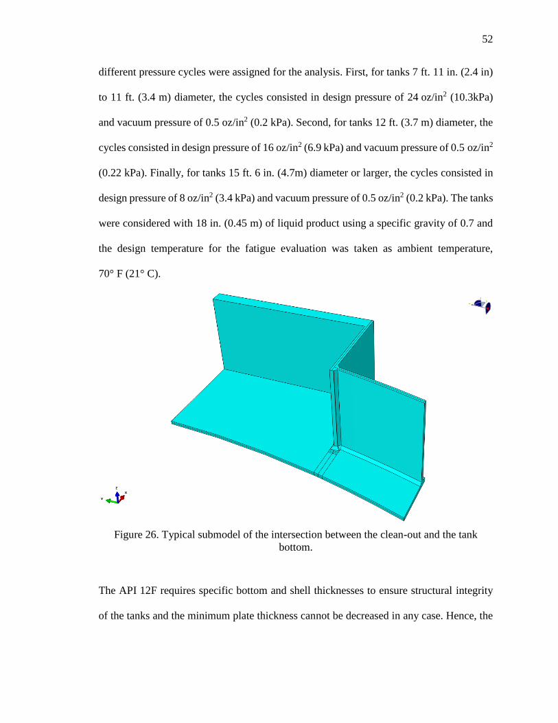
52
different pressure cycles were assigned for the analysis. First, for tanks 7 ft. 11 in. (2.4 in)
to 11 ft. (3.4 m) diameter, the cycles consisted in design pressure of 24 oz/in2 (10.3kPa)
and vacuum pressure of 0.5 oz/in2 (0.2 kPa). Second, for tanks 12 ft. (3.7 m) diameter, the
cycles consisted in design pressure of 16 oz/in2 (6.9 kPa) and vacuum pressure of 0.5 oz/in2
(0.22 kPa). Finally, for tanks 15 ft. 6 in. (4.7m) diameter or larger, the cycles consisted in
design pressure of 8 oz/in2 (3.4 kPa) and vacuum pressure of 0.5 oz/in2 (0.2 kPa). The tanks
were considered with 18 in. (0.45 m) of liquid product using a specific gravity of 0.7 and
the design temperature for the fatigue evaluation was taken as ambient temperature,
70° F (21° C).
Figure 26. Typical submodel of the intersection between the clean-out and the tank
bottom.
The API 12F requires specific bottom and shell thicknesses to ensure structural integrity
of the tanks and the minimum plate thickness cannot be decreased in any case. Hence, the

53
bottom and shell thicknesses of the models were assigned considering the tank diameters
and the three different groups mentioned before. Thus, a 3/16 in. (4.8 mm) shell and 1/4 in.
(6.4 mm) bottom were used for the small diameter group, 1/4 in. (6.4 mm) shell and 1/4 in.
(6.4 mm) bottom were used for the medium diameter group, and a 1/4 in. (6.4 mm) shell
and 3/8 in. (9.5 mm) bottom were used for the large diameter group. As stated in the
API 12F, the roof plates have the same the thickness as the shell plates. Table 12
summarized the pressure cycles and thicknesses assigned to each tank model.
Table 12. Summary of pressure cycles and thicknesses in the tank models.
Pressure Cycle (oz/in², kPa) Diameter
ft, in (m)
Height
ft, m
Shell
Thickness
in, mm
Bottom
Thickness
in, mm Design
Pressure
Vacuum
Pressure
Case 1 24, 10.3 0.5, 0.2 7-11 (2.4) 10, 3.0 3/16, 4.8 1/4, 6.4
Case 2 24, 10.3 0.5, 0.2 9-6 (2.9) 8, 2.4 3/16, 4.8 1/4, 6.4
Case 3 24, 10.3 0.5, 0.2 9-6 (2.9) 12, 3.7 3/16, 4.8 1/4, 6.4
Case 4 16, 6.9 0.5, 0.2 12-0 (3.7) 10, 3.0 1/4, 6.4 1/4, 6.4
Case 5 24, 10.3 0.5, 0.2 10-0 (3.0) 15, 4.6 3/16, 4.8 1/4, 6.4
Case 6 24, 10.3 0.5, 0.2 11-0 (3.4) 15, 4.6 3/16, 4.8 1/4, 6.4
Case 7 16, 6.9 0.5, 0.2 12-0 (3.7) 15, 4.6 1/4, 6.4 1/4, 6.4
Case 8 16, 6.9 0.5, 0.2 12-0 (3.7) 20, 6.1 1/4, 6.4 1/4, 6.4
Case 9 16, 6.9 0.5, 0.2 12-0 (3.7) 25, 7.6 1/4, 6.4 1/4, 6.4
Case 10 8, 3.4 0.5, 0.2 15-6 (4.7) 16, 4.9 1/4, 6.4 3/8, 9.5
Case 11 8, 3.4 0.5, 0.2 15-6 (4.7) 24, 7.3 1/4, 6.4 3/8, 9.5
Case 12 8, 3.4 0.5, 0.2 15-6 (2.4) 30, 9.1 1/4, 6.4 3/8, 9.5
Case 13 8, 3.4 0.5, 0.2 21-6 (2.9) 16, 4.9 1/4, 6.4 3/8, 9.5
The soil-structure interaction was considered by using linear elastic springs in the bottom
of the tank models acting in vertical direction. In this way, only compression springs were
utilized in the analysis. An iterative method was employed to remove all the springs in
tension after applying the design pressure. Moreover, it was observed that the vacuum
pressure produced the tanks bottom to settle. Therefore, several configurations were

54
considered in the analysis to support the tanks base. Compacted sand soil, reinforced
concrete pad, and a combination of sand soil under the tank bottom with concrete ringwalls
under the tank shell were studied to determine the most conservative support condition for
the tank models. Finally, the properties of a compacted sand soil were utilized in the
analysis and subgrade modulus of 250 lbf/in3 (68000 kN/m3) [8] was assigned to the
springs stiffness to represent the soil material.
3.4 Fatigue Evaluation - Elastic Stress Analysis
The stress analysis was performed following the ASME design-by-analysis rules
mentioned in Section 3.2.2. The stress components were obtained from the results using
ABAQUS and the stress tensor range and the range of primary plus secondary plus peak
equivalent stress were computed using Equations (6) and (7).
As mentioned before, the effective alternating equivalent stress is defined as one-half of
the effective total equivalent stress range multiplied by a fatigue penalty factor and a fatigue
strength reduction factor. In order to obtain the fatigue penalty factor as well as carry out
the ratcheting analysis, the primary plus secondary equivalent stress range had to be
computed. Thus, a linearization of the results was made to categorize the stresses and the
primary plus secondary equivalent stress range was computed as directed in the ASME
code. For the axisymmetric models, the linearization was made in different stress
classification lines (SCL) across the roof-to-shell and shell-to-bottom joints of the tanks as
shown in Figure 27. Both the inside and outside points of the SCL were studied and the
fatigue life of the tanks were estimated according to the alternating stresses obtained in
these points. Figure 28 shows a typical stress classification for a cross section of the tank

55
models. For the solid submodels, the stress linearization of the stress components was
performed in a cross-section of the tanks bottom along the partitions located at 0.4t, 0.9t,
and 1.4t from the weld toe. Hence, the results were extrapolated to find the stress
components at the intersection points and compute the primary plus secondary equivalent
stress range.
(a) (b)
(c) (d)
(e)
(f)
Figure 27. Stress Classification Lines
SCL 1
SCL 2
SCL 4
SCL 5
SCL 6
SCL 3

56
In cases where the primary plus secondary equivalent stress ranges were smaller than the
allowable limit, the protection against ratcheting was checked and the assigned fatigue
penalty factor, Ke,k, was equal to 1.0 for the fatigue evaluation. However, if the primary
plus secondary equivalent stress ranges were larger than the allowable limit, the fatigue
penalty factor, Ke,k, was computed in accordance with the ASME formulation. The material
constants m and n for carbon steel were 3.0 and 0.2, respectively.
The fatigue strength reduction factor depends on the type of welding and surface finish of
the tanks as well as the examination done to the welds. The roof-to-shell and shell-to-
bottom joints consisted of fillet welds, both inside and outside. It was assumed for the
evaluation points along SCL 1 to 4 located at the toe that the welds only received VT
examination (visual), and for the evaluation points along SCL 5 and 6 located at the
backside of the fillet welds, the welds received no examination. Therefore, the assigned
fatigue strength reduction factor for SCL 1 to 4 was Kf, = 2.5 and for SCL 5 to 6, Kf, = 4.0
as stated in Table 5.12 from the ASME Boiler and Pressure Vessel Code [15].

57
Figure 28. Typical stress classification for a cross section
After computing the effective alternating equivalent stress, the number of permissible
cycles was obtained using Equation (9). These results were compared to the S-N curves
provided in the ASME Boiler and Pressure Vessel Code, Section VIII, Division 2, 2004
Edition. The 2004 edition was the last one that included the design fatigue curves for
different materials instead of providing the formulation to compute the number of cycles.
This procedure was carried out to check the validity of the results. A smooth bar design
fatigue curve obtained by following the formulation presented in the Annex 3-F of the
ASME code is shown in Figure 29.
0 0.05 0.1 0.15 0.2 0.25
Str
ess
Distance along cross-section
Stress Component
Membrane Stress
Membrane plus Bending Stress

58
Figure 29. Smooth bar design fatigue curve for Carbon, Low Alloy, Series 4xx, and High
Tensile Strength Steels for temperatures not exceeding 371°C (700°F) where
Ϭ𝑢𝑡𝑠≤ 80 Ksi (552 MPa)
The permissible pressure cycles obtained after evaluating the top and bottom joints using
axisymmetric models of each API 12F tank are presented in Table 13. It can be observed
that the number of allowable cycles obtained from the SCL 1 and 2 do not increase with
the height of the tanks. However, the stress classification lines at the shell-to-bottom joint
(SCL 3 and 4) indicate that tanks with smaller height tend to have a shorter fatigue life than
tanks with larger height. Moreover, for tanks with 11 ft (3.4 m) diameter or smaller, the
allowable number of pressure cycles was dictated from the behavior of the shell-to-bottom
joints instead of the roof-to-shell joints as recommended by the API 937 for storage tanks
with frangible roof joint. It is also important to note that the inside evaluation points
reflected less number of permissible cycles than the outside points.
The pressure cycles computed after the evaluation of stresses in the joint between the clean-
out attachment and the tank base using solid submodels and the extrapolation method are
1.E+03
1.E+04
1.E+05
1.E+06
1.E+03 1.E+04 1.E+05 1.E+06 1.E+07 1.E+08 1.E+09
Sal
t, p
si
Number of Cycles, N

59
presented in Table 14. From the results, it can be noted that tanks with smaller diameters
allow less pressure cycles than tanks with larger diameters. Moreover, the groups of tanks
with 12 ft. (3.7 m) diameter demonstrated that the selfweight of the shell reduces the
deformation and equivalent stress range produced in the clean out joint due to internal
pressure and vacuum, increasing the permissible pressure cycles. Finally, comparing the
number of cycles computed after evaluating the top and bottom joints as well as the clean-
out joint, the minimum allowable cycles for each API 12F is presented in Figure 30.

60
Table 13. Number of permissible cycles at the top and bottom joints of API 12F shop
welded tanks
Case
Pressure Cycle
(oz/in², kPa)
SCL 1
(Cycles)
SCL 2
(Cycles)
SCL 3
(Cycles) Min
number
of cycles Design
Pressure
Vacuum
Pressure
Inside
Point
Outside
Point
Inside
Point
Outside
Point
Inside
Point
Outside
Point
1 24, 10.3 0.5, 0.2 1.5E+05 4.0E+05 1.9E+05 5.6E+05 4.8E+04 5.9E+04 4.8E+04
2 24, 10.3 0.5, 0.2 3.1E+04 9.5E+04 5.2E+04 1.4E+05 1.4E+04 1.5E+04 1.4E+04
3 24, 10.3 0.5, 0.2 3.1E+04 9.5E+04 5.3E+04 1.4E+05 1.7E+04 1.9E+04 1.7E+04
4 16, 6.9 0.5, 0.2 1.8E+05 1.9E+06 3.6E+05 4.1E+06 3.5E+05 4.8E+05 1.8E+05
5 24, 10.3 0.5, 0.2 3.3E+04 1.0E+05 5.4E+04 1.5E+05 2.5E+04 3.2E+04 2.5E+04
6 24, 10.3 0.5, 0.2 2.3E+04 5.9E+04 3.4E+04 7.8E+04 1.7E+04 2.1E+04 1.7E+04
7 16, 6.9 0.5, 0.2 1.8E+05 1.9E+06 3.6E+05 4.2E+06 4.9E+06 2.3E+07 1.8E+05
8 16, 6.9 0.5, 0.2 1.8E+05 1.9E+06 3.6E+05 4.1E+06 1.2E+09 6.5E+09 1.8E+05
9 16, 6.9 0.5, 0.2 1.8E+05 1.9E+06 3.6E+05 4.1E+06 1.6E+11 3.3E+11 1.8E+05
10 8, 3.4 0.5, 0.2 5.3E+05 2.1E+08 3.7E+06 3.9E+08 1.3E+07 1.5E+06 5.3E+05
11 8, 3.4 0.5, 0.2 5.3E+05 2.1E+08 3.8E+06 3.9E+08 2.9E+08 2.6E+07 5.3E+05
12 8, 3.4 0.5, 0.2 6.1E+05 2.1E+08 3.7E+06 3.9E+08 9.0E+06 1.1E+06 6.1E+05
13 8, 3.4 0.5, 0.2 6.3E+04 2.8E+05 9.9E+04 2.5E+05 1.4E+10 5.9E+10 6.3E+04
Case
Pressure Cycle
(oz/in², kPa)
SCL 3
(Cycles)
SCL 4
(Cycles)
SCL 5
(Cycles) Min
number
of cycles Design
Pressure
Vacuum
Pressure
Inside
Point
Outside
Point
Inside
Point
Outside
Point
Inside
Point
Outside
Point
1 24, 10.3 0.5, 0.2 2.2E+05 4.4E+05 1.4E+05 1.5E+06 4.3E+05 2.6E+11 4.8E+04
2 24, 10.3 0.5, 0.2 1.5E+04 1.6E+04 2.9E+04 6.8E+04 3.7E+04 1.9E+05 1.4E+04
3 24, 10.3 0.5, 0.2 4.3E+04 7.5E+04 4.2E+04 2.0E+05 8.0E+04 2.3E+08 1.7E+04
4 16, 6.9 0.5, 0.2 2.0E+05 4.6E+05 2.5E+05 7.6E+07 5.3E+07 2.8E+08 1.8E+05
5 24, 10.3 0.5, 0.2 7.4E+04 2.2E+05 4.3E+04 2.0E+05 1.2E+05 9.5E+10 2.5E+04
6 24, 10.3 0.5, 0.2 4.1E+04 1.1E+05 2.9E+04 1.0E+05 5.8E+04 1.9E+09 1.7E+04
7 16, 6.9 0.5, 0.2 8.9E+05 2.6E+07 2.5E+05 7.6E+07 1.8E+10 * 1.8E+05
8 16, 6.9 0.5, 0.2 3.6E+08 3.4E+09 2.5E+05 7.3E+07 2.7E+11 * 1.8E+05
9 16, 6.9 0.5, 0.2 1.1E+11 3.2E+11 3.6E+05 7.6E+07 7.7E+08 * 1.8E+05
10 8, 3.4 0.5, 0.2 * * 9.1E+05 5.5E+09 * * 5.3E+05
11 8, 3.4 0.5, 0.2 * * 4.1E+06 6.4E+09 * * 5.3E+05
12 8, 3.4 0.5, 0.2 * * 9.2E+05 1.7E+11 * * 6.1E+05
13 8, 3.4 0.5, 0.2 * * 7.5E+04 4.7E+05 1.1E+07 * 6.3E+04
* Stress was too small to obtain an accurate result.

61
Table 14. Number of allowable pressure cycles at clean-out joints of API 12F shop
welded flat bottom tanks
Pressure Cycle (oz/in², kPa) Diameter
ft, in (m)
Height
ft, m
Minimum
number of
cycles Design Pressure Vacuum Pressure
Case 1 24, 10.3 0.5, 0.2 7, 11 (2.4) 10, 3.0 2.3E+04
Case 2 24, 10.3 0.5, 0.2 9, 6 (2.9) 8, 2.4 4.0E+03
Case 3 24, 10.3 0.5, 0.2 9, 6 (2.9) 12, 3.7 7.2E+03
Case 4 16, 6.9 0.5, 0.2 12, 0 (3.7) 10, 3.0 9.0E+03
Case 5 24, 10.3 0.5, 0.2 10, 0 (3.0) 15, 4.6 6.2E+03
Case 6 24, 10.3 0.5, 0.2 11, 0 (3.4) 15, 4.6 4.8E+03
Case 7 16, 6.9 0.5, 0.2 12, 0 (3.7) 15, 4.6 1.5E+04
Case 8 16, 6.9 0.5, 0.2 12, 0 (3.7) 20, 6.1 2.3E+04
Case 9 16, 6.9 0.5, 0.2 12, 0 (3.7) 25, 7.6 4.7E+04
Case 10 8, 3.4 0.5, 0.2 15, 6 (4.7) 16, 4.9 6.7E+07
Case 11 8, 3.4 0.5, 0.2 15, 6 (4.7) 24, 7.3 1.4E+08
Case 12 8, 3.4 0.5, 0.2 7, 11 (2.4) 10, 3.0 8.5E+06
Case 13 8, 3.4 0.5, 0.2 9, 6 (2.9) 8, 2.4 8.4E+04

62
Figure 30. Minimum number of cycles for each API 12F tank and location of the most
critical joint.
Clean
out Clean
out
Clean
out
Clean
outClean
outClean
out
Clean
out
Clean
out
Clean
out
Top
Joint
Top
Joint
Top
JointTop
Joint
1.E+00
1.E+01
1.E+02
1.E+03
1.E+04
1.E+05
1.E+06
1 2 3 4 5 6 7 8 9 10 11 12 13
Cycles 2.3E+04 4.0E+03 7.2E+03 9.0E+03 6.2E+03 4.8E+03 1.5E+04 2.3E+04 4.7E+04 5.3E+05 5.3E+05 6.1E+05 6.3E+04
All
ow
able
Nu
mb
er o
f C
ycl
es
Case

63
3.5 Conclusions
An elastic stress analysis was performed to study fatigue life of the API 12F shop-welded
tanks in accordance with the ASME Boiler and Pressure Vessel Code. Section VIII.
Division 2, 2013 Edition. Three different joints were evaluated throughout this research:
the roof-to-shell joint, the shell-to-bottom joint and the clean-out intersection with the tank
bottom. While axisymmetric models were built to study the first two joints, 3D solid
submodels were constructed to determine the allowable number of pressure cycles in the
clean-out juncture. This study yields the following conclusions:
The permissible number of pressure cycles was determined and summarized in
Figure 30. The most critical API 12F storage tank in terms of fatigue evaluation
was the Case 2 (9 ft 6 in (2.9 m) diameter and 8 ft (2.4 m) high) which allows
approximately four thousand cycles.
The evaluation of the three referred joints proved that the height of the tank and the
selfweight of the shell increase the number of permissible cycles especially in tanks
with smaller diameter (12 ft (3.7 m) or less) because they reduce the deformation
at the bottom of the equipment.
The analysis of top and bottom joints using axisymmetric models revealed that for
tanks with 12 ft (3.7 m) diameter or smaller, the shell-to-bottom joint has a shorter
fatigue life than the roof-to-shell joint. Hence, the fatigue analysis estimated that
the bottom of the tanks fail prior to the top joint, producing an oil spillage hazard.
The study of the clean out juncture to the base of the tanks determined that this
intersection is critical in the fatigue life of API 12F tanks with 12ft (3.7m) diameter

64
and smaller. For the tanks 15ft. 6in. (4.7 m) diameter or larger, the behavior of the
top joint was more significant in the estimation of permissible pressure cycles.

65
CHAPTER 4. CONCLUSION
4.1 Failure Pressure of the API 12F Storage Tanks
Various failure pressure modes were study throughout this investigation, the yielding
pressure of each API 12F tank model was determined using an elastic stress analysis. In
general, the storage tanks failed at the top joint before yielding occur at the bottom joint.
Only five cases did not ensure the frangible roof joint behavior representing a hazard if
these tanks are subjected to overpressure. Additionally, yielding pressure obtained from
the finite element analysis of the tanks was always greater than the pressure computed
using the API 937 formulation.
Even though the estimation of the uplift deformations calculated using FEA and the
API 937 or API 650 formulations resulted in similar results, the FE models showed that
the API 650 uplift criteria might be too conservative to the API 12F shop-welded tanks.
The equipment were capable of resisting further internal pressure after some uplift occurred
at the base.
The design pressure for the studied tanks was raised up to 24 oz/in2 (10.3 kPa), which did
not cause failure in any tank top or bottom joints. However, significant uplift deformations
were observed in the group of tanks with 15ft. 6in diameter and larger. Further
investigation is recommended to determine if the increase in the design pressure might
affect the safety of the equipment.

66
In general, the elastic buckling analysis showed that the buckling pressures of the API 12F
tanks are greater than the yielding pressures. Only the tank models with 21ft. 6in diameter
presented some buckling before the yielding failure occurred at the top joint.
The elastic-plastic stress analysis evaluated the plastic collapse of the equipment. It was
observed that rupture occurred at the top joint of the tanks in all the cases studied. Moreover,
the rupture-to-yielding ratios ranged from 1.4 to 6.4
Additionally, rupture at the intersection of the clean-out with the tank bases was observed
in the elastic-plastic analysis of the models. Thus, a fatigue analysis was recommended and
addressed in Chapter 3 of this document.
The wind load analysis indicated low stress levels and small uplift deformations. It was
concluded that the wind pressure was not critical in the analysis of the tank failure modes.
4.2 Fatigue Analysis of the API 12F Tanks
The fatigue evaluation was developed using an elastic stress analysis of the API 12F tanks.
The allowable number of pressure cycles were estimated by analyzing three critical joints
in the tank models: the roof-to-shell joint, the shell-to-bottom joint, and the intersection
between the clean-out and the tank bottom. The first two joints were modeled with
axisymmetric models and the third one was analyzed with solid elements and using
submodeling techniques.
It was observed that for tanks with a diameter of 12ft and smaller, the clean-out intersection
presented a shorter fatigue life than the other junctures. On the other hand, tanks with a
15ft. 6in diameter and larger showed that the most critical joint in terms of permissible
pressure cycles was the roof-to-shell joint.

LIST OF REFERENCES

67
LIST OF REFERENCES
[1] API 12F, Specification for shop welded tanks for storage of production liquids,
Twelfth Edition. Washington, D.C.: American Petroleum Institute; 2008.
[2] Myers, P. E. Aboveground storage tanks. Vol. 690. McGraw-Hill, 1997.
[3] Jaca, R C., and Godoy L A., Wind buckling of metal tanks during their
construction. Thin-Walled Structures, 2010; 48.6: 453-459.
[4] Drogaris, G. K. Major accidents in oil and gas industries. SPE Health, Safety and
Environment in Oil and Gas Exploration and Production Conference. Society of
Petroleum Engineers, 1991.
[5] API 937, Evaluation of design criteria for storage tanks with frangible roof joints.
Washington, D.C.: American Petroleum Institute; 1996.
[6] Lu, Zhi. Evaluation of design criteria for storage tanks with frangible roof joints. Diss.
Kansas State University, 1994.
[7] API 650, Welded tanks for oil storage, Twelfth Edition. Washington, D.C.: American
Petroleum Institute; 2013.

68
[8] Swenson, D., Fenton, D., Lu, Z., Ghori, A., and Baalman, J., Evaluation of Design
Criteria for Storage Tanks with Frangible Roof Joints, Welding Research Council
Bulletin 410, ISSN 0043-2326, Welding Research Council, United Engineering
Center, 345 East 47th Street, New York, NY, 10017, April, 1996.
[9] ASTM A36. Standard Specification for Carbon Structural Steel. 2008.
[10] ABAQUS. Abaqus Analysis User's Manual version 6.13. Providence, RI: Dassault
Systemes Simulia Corp.; 2013.
[11] Niemi, E., Fricke, W., Maddox, S.J., Fatigue analysis of welded joints - Designer's
guide to the structural hot-spot stress approach, IIW Doc IIW-1430-00, Cambridge,
Woodhead: International Institute of Welding; 2006
[12] Ellobody, E., Feng R., and Young B. Finite Element Analysis and Design of Metal
Structures. Elsevier, 2013.
[13] Wang, J. H., and A. Koizumi. Buckling of cylindrical shells with longitudinal joints
under external pressure. Thin-Walled Structures 2010; 48.12: 897-904.
[14] API 579-1/ASME FFS-1, Fitness-For-Service, Second Edition. Washington, D.C.:
American Petroleum Institute; 2007.
[15] ASME Boiler and Pressure Vessel Code, Section VIII. Alternative rules for
construction of pressure vessels, Division 2. New York, NY: American Society of
Mechanical Engineers; 2013.
[16] Riks, E., An incremental approach to the solution of snapping and buckling problems.
Int. J. Solids & Struct. 1979; 15(7):529-551.

69
[17] Maraveas, C., Balokas, G. A., and Tsavdaridis, K. D. Numerical evaluation on shell
buckling of empty thin-walled steel tanks under wind load according to current
American and European design codes. Thin-Walled Structures 2015; 95: 152-160.
[18] Zhao, Y., and Lin, Y. Buckling of cylindrical open-topped steel tanks under wind
load. Thin-Walled Structures, 2014 79: 83-94.
[19] Zhao, Y., Cao, Q. S., and Su, L. Buckling design of large circular steel silos subject
to wind pressure. Thin-Walled Structures, 2013; 73: 337-349.
[20] Prinz, GS, and Nussbaumer A. Fatigue analysis of liquid-storage tank shell-to-base
connections under multi-axial loading. Engineering Structures 2012, 40: 75-82
[21] Prinz, GS, and Nussbaumer A. On the low-cycle fatigue capacity of unanchored steel
liquid storage tank shell-to-base connections. Bulletin of Earthquake Engineering,
2012: 10.6: 1943-1958.
[22] Ahari MN, Eshghi S, Ashtiany MG. The tapered beam model for bottom plate uplift
analysis of unanchored cylindrical steel storage tanks. Engineering Structures 2009;
31:623–32.
[23] Malhotra PK, Veletsos AS. Uplifting analysis of base plates in cylindrical tanks.
Journal of Structural Engineering 1994; 120(12):3489–505.
[24] Malhotra PK. Base uplifting analysis of flexibly supported liquid-storage tanks.
Earthquake engineering & structural dynamics 1995; 24:1591–607.

PUBLICATIONS
70
PUBLICATIONS
Journal Papers:
Rondon A, Guzey S. Determination of localized stresses in the shell above anchor bolt
chairs attachments of anchored storage tanks. Thin-Walled Structures 2016; 98: 617-626.
Rondon A, Guzey S. Failure Pressure of the API Specification 12F Shop Welded, Flat
Bottom Tanks. Thin-Walled Structures. (Paper Submitted)
Conference Proceedings
Rondon A, Guzey S. Evaluation of the Anchor-Bolt Chair Design Considering Localized
Stresses in the Shell of Anchored Storage Tanks. ASME 2016 Pressure Vessels and
Piping Conference. (Final Paper Submitted)
Rondon A, Guzey S. Evaluation of the Design Pressure and Failure modes for the API
12F Shop Welded Flat Bottom Tanks for oil storage. ASME 2016 Pressure Vessels and
Piping Conference. (Final Paper Submitted)