Embed Size (px)
Citation preview
FAGOR AUTOMATION MC TRAINING MANUAL
1.25
6
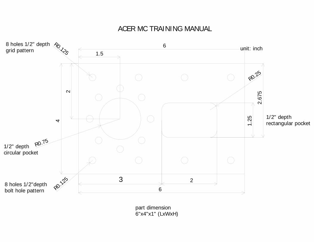
28 holes 1/2"depth bolt hole pattern
8 holes 1/2" depthgrid pattern
R0.25
unit: inch
1/2" depthrectangular pocket
1/2" depthcircular pocket
part dimension6"x4"x1" (LxWxH)
ACER MC TRAINING MANUAL
3
R0.75
1.56
2
4
R0.12
5
R0.125
2.67
5
INDEX
Introduction………………………………………………………………..3
Reference Search…………………………………………………………..4
Tool Calibration……………………………………………………………5
Presetting Part Zero………………………………………………………..7
Surface Milling…………………………………………………………….8
Simulation………………………………………………………………….10
Storing Part Program………………………………………………………11
Circular Pocket…………………………………………………………….13
Rectangular Pocket………………………………………………………...16
Drilling + Rectangular Position……………………………………………19
Drilling + Arc Position…………………………………………………….22
Zero Offsets………………………………………………………………..26
ISO Mode………………………………………………………………….28
Inserting Code In-Between Canned Cycles……………………………….29
Tool Inspection…………………………………………………………….32
Quick Reference Guide…………………………………………………….35
INTRODUCTION This manual has been generated to be a guideline for your assistance for the conversational programming of the Fagor control. In this manual we will be generating a part-program using the canned cycles that will be the most beneficial for your programming needs. In this manual we will be exercising the following operations:
• Homing of the Axes • Tool Calibration • Presetting your Zero • Surface Milling • Pockets • Drilling • Simulation/Graphics • File Maintenance
After the completion of these operations, you will begin to understand all the steps that are necessary in programming the Fagor CNC Control. Once you grasp each of these concepts you will be able generate any part in which you desire. Using this manual as your guideline will also help you generate part-programs in a timely manner. You will soon realize once you learn the programming of one canned cycle, you will understand the programming concept of each and every one of the other canned cycles. Whether it is your first time using a CNC or if you are a CNC programming expert, the conversational programming of the Fagor CNC Control will benefit all users.
3
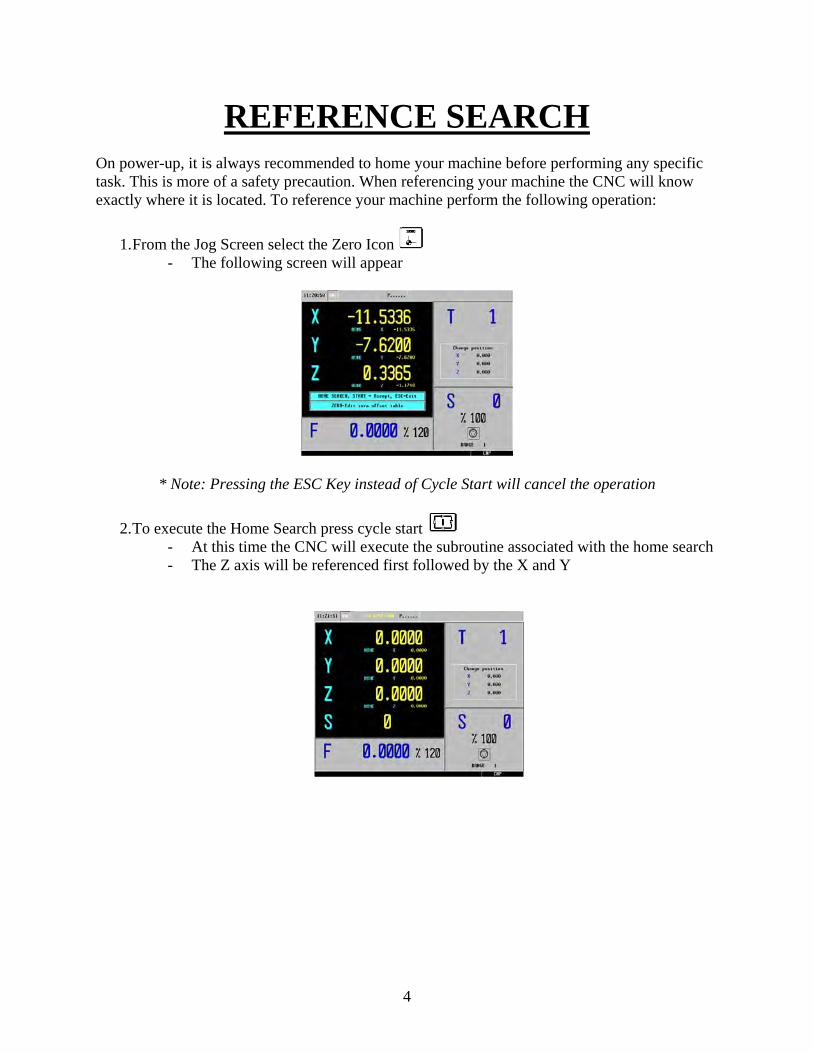
REFERENCE SEARCH On power-up, it is always recommended to home your machine before performing any specific task. This is more of a safety precaution. When referencing your machine the CNC will know exactly where it is located. To reference your machine perform the following operation:
1. From the Jog Screen select the Zero Icon - The following screen will appear
* Note: Pressing the ESC Key instead of Cycle Start will cancel the operation
2. To execute the Home Search press cycle start - At this time the CNC will execute the subroutine associated with the home search - The Z axis will be referenced first followed by the X and Y
4
TOOL CALIBRATION
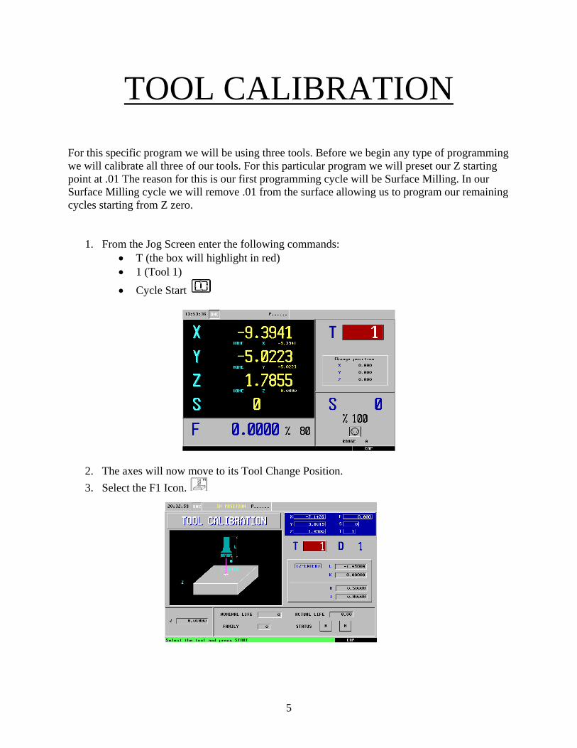
For this specific program we will be using three tools. Before we begin any type of programming we will calibrate all three of our tools. For this particular program we will preset our Z starting point at .01 The reason for this is our first programming cycle will be Surface Milling. In our Surface Milling cycle we will remove .01 from the surface allowing us to program our remaining cycles starting from Z zero.
1. From the Jog Screen enter the following commands: • T (the box will highlight in red) • 1 (Tool 1) • Cycle Start
2. The axes will now move to its Tool Change Position. 3. Select the F1 Icon.
5
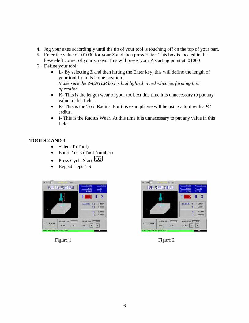
4. Jog your axes accordingly until the tip of your tool is touching off on the top of your part. 5. Enter the value of .01000 for your Z and then press Enter. This box is located in the
lower-left corner of your screen. This will preset your Z starting point at .01000 6. Define your tool:
• L- By selecting Z and then hitting the Enter key, this will define the length of your tool from its home position. Make sure the Z-ENTER box is highlighted in red when performing this operation.
• K- This is the length wear of your tool. At this time it is unnecessary to put any value in this field.
• R- This is the Tool Radius. For this example we will be using a tool with a ½’ radius.
• I- This is the Radius Wear. At this time it is unnecessary to put any value in this field.
TOOLS 2 AND 3
• Select T (Tool) • Enter 2 or 3 (Tool Number) • Press Cycle Start • Repeat steps 4-6
Figure 1 Figure 2
6
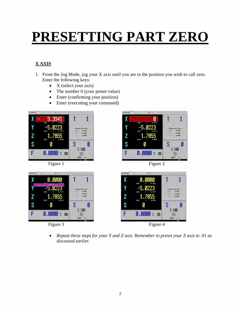
PRESETTING PART ZERO X AXIS 1. From the Jog Mode, jog your X axis until you are to the position you wish to call zero.
Enter the following keys: • X (select your axis) • The number 0 (your preset value) • Enter (confirming your position) • Enter (executing your command)
Figure 1 Figure 2
Figure 3 Figure 4
• Repeat these steps for your Y and Z axis. Remember to preset your Z axis to .01 as
discussed earlier.
7
SURFACE MILLING
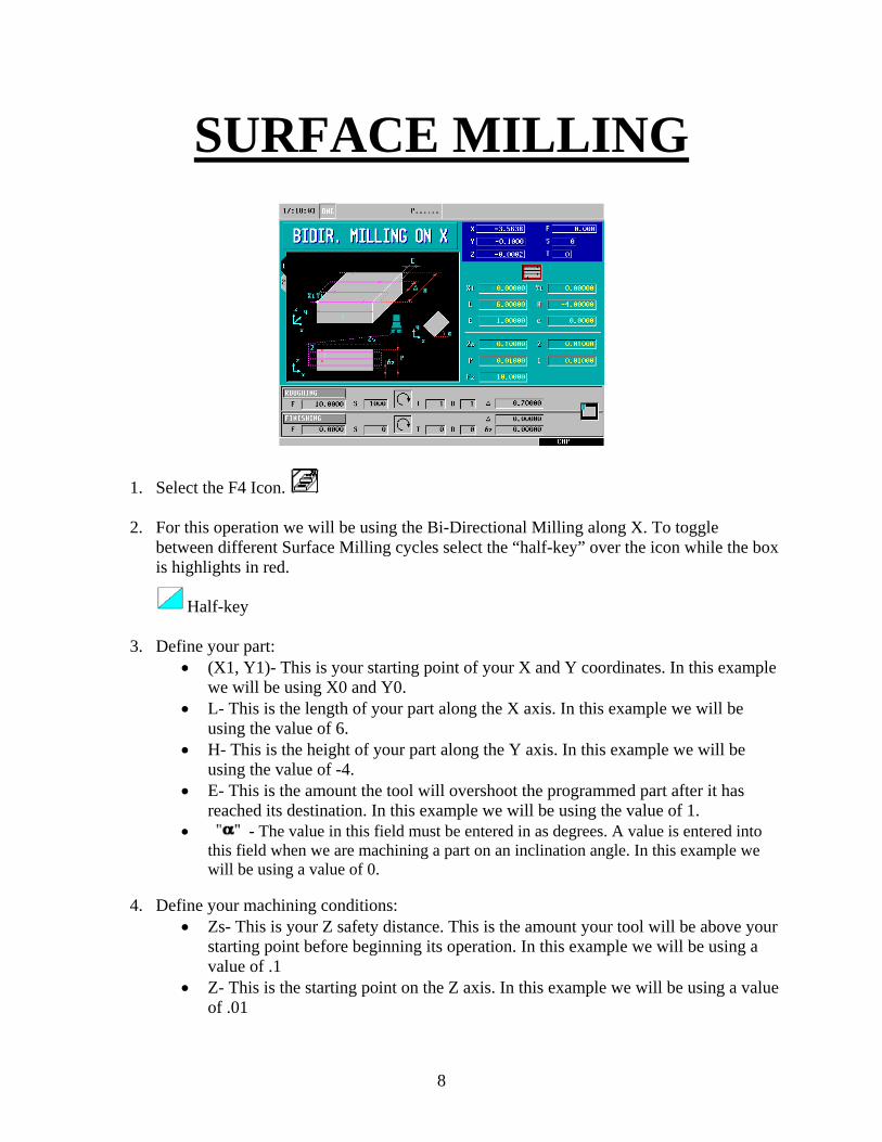
1. Select the F4 Icon. 2. For this operation we will be using the Bi-Directional Milling along X. To toggle
between different Surface Milling cycles select the “half-key” over the icon while the box is highlights in red.
Half-key 3. Define your part:
• (X1, Y1)- This is your starting point of your X and Y coordinates. In this example we will be using X0 and Y0.
• L- This is the length of your part along the X axis. In this example we will be using the value of 6.
• H- This is the height of your part along the Y axis. In this example we will be using the value of -4.
• E- This is the amount the tool will overshoot the programmed part after it has reached its destination. In this example we will be using the value of 1.
• - The value in this field must be entered in as degrees. A value is entered into this field when we are machining a part on an inclination angle. In this example we will be using a value of 0.
4. Define your machining conditions:
• Zs- This is your Z safety distance. This is the amount your tool will be above your starting point before beginning its operation. In this example we will be using a value of .1
• Z- This is the starting point on the Z axis. In this example we will be using a value of .01
8
• P- This is the total depth we will be removing off the surface of the material. In this example we will be using the value of .01
• I- This is the amount we will be removing off the surface of the material per pass. In this example we will be using the value of .01 meaning it will only take one pass to get to its final depth.
• Fz- This is the penetration feedrate. This value is entered in inches per minute. In this example we will be using the value of 10.
5. Define your Roughing Pass:
• F- This is your roughing feedrate along the axis. In this example we are using a value of 10 inches per minute.
• S- This is your spindle speed. In this example we are using a value of 1000 rpm.
• Select your spindle direction. To toggle between directions push the “half-key”. In this example we will be using a Clockwise Rotation.
• T- Enter is your tool number. In this example we are using T1. • D- Enter in your Tool Offset Number. In this example we are using D1. • This is your milling step-over. To ensure nice clean cuts enter in a value less
than the diameter of your tool. • Finally, select the corner you would like to begin milling. To toggle between
options push the half-key. In this example we will be beginning in the upper-left corner.
9
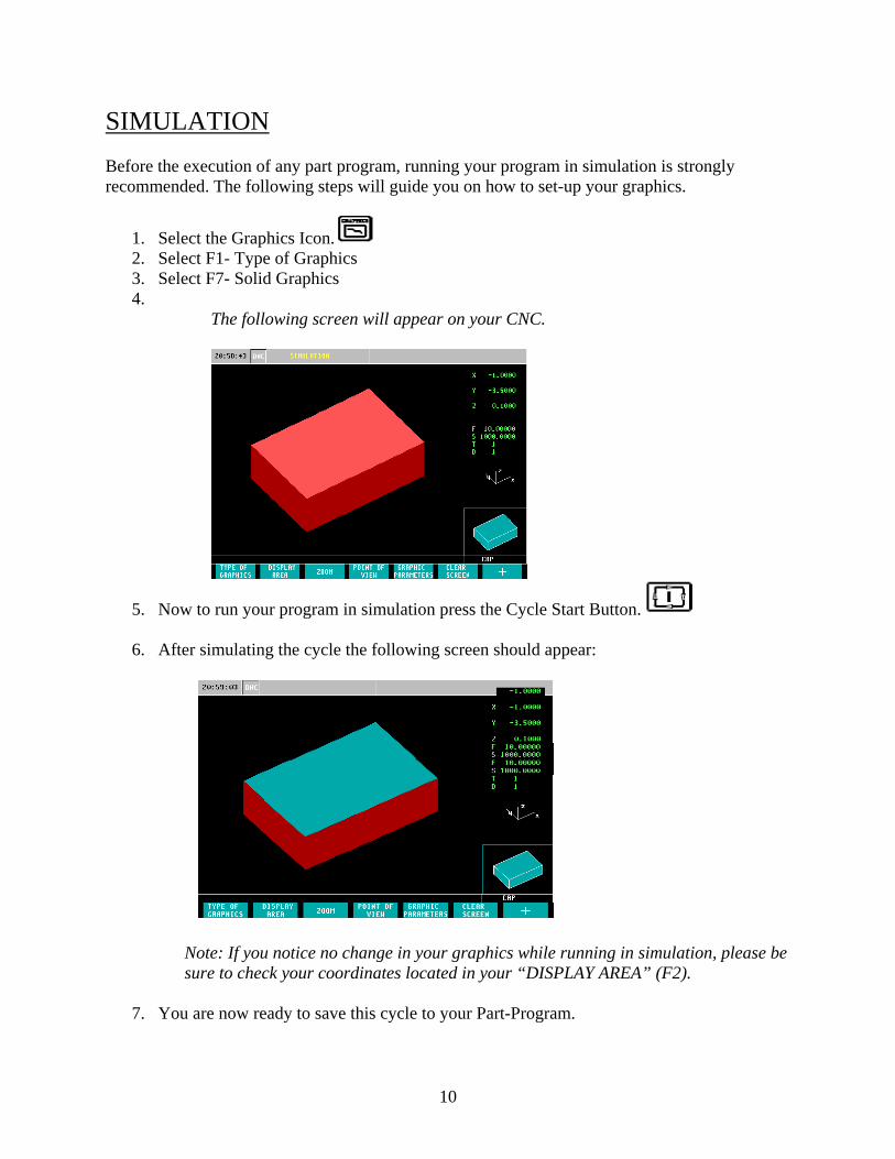
SIMULATION Before the execution of any part program, running your program in simulation is strongly recommended. The following steps will guide you on how to set-up your graphics.
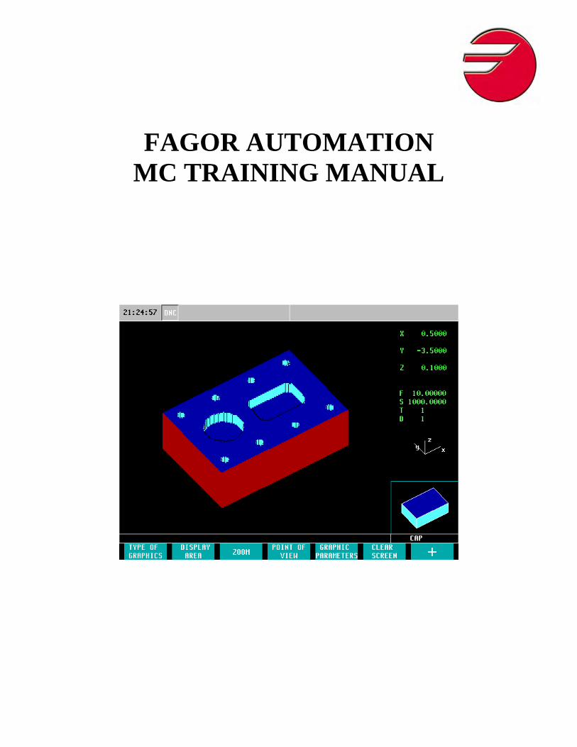
1. Select the Graphics Icon. 2. Select F1- Type of Graphics 3. Select F7- Solid Graphics 4.
The following screen will appear on your CNC.
5. Now to run your program in simulation press the Cycle Start Button. 6. After simulating the cycle the following screen should appear:
Note: If you notice no change in your graphics while running in simulation, please be sure to check your coordinates located in your “DISPLAY AREA” (F2).
7. You are now ready to save this cycle to your Part-Program.
10
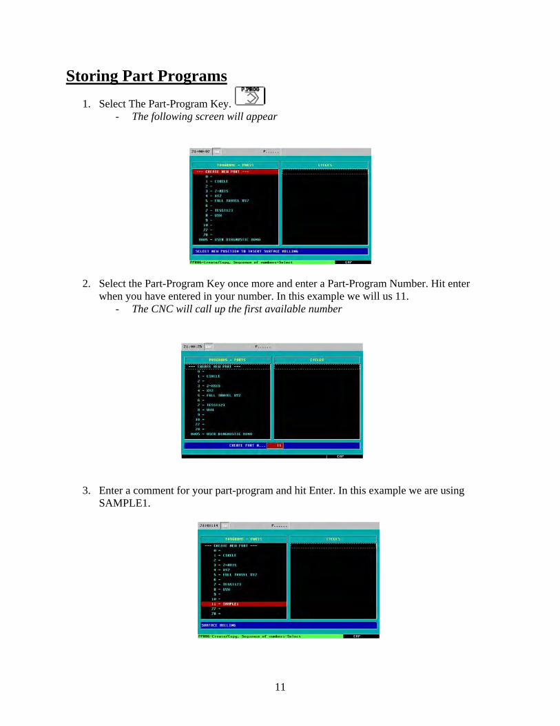
Storing Part Programs 1. Select The Part-Program Key.
- The following screen will appear
2. Select the Part-Program Key once more and enter a Part-Program Number. Hit enter when you have entered in your number. In this example we will us 11.
- The CNC will call up the first available number
3. Enter a comment for your part-program and hit Enter. In this example we are using SAMPLE1.
11
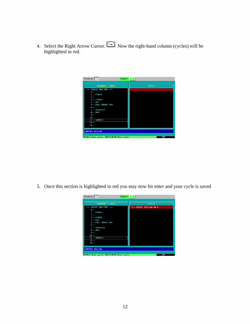
4. Select the Right Arrow Cursor. Now the right-hand column (cycles) will be highlighted in red.
5. Once this section is highlighted in red you may now hit enter and your cycle is saved
12
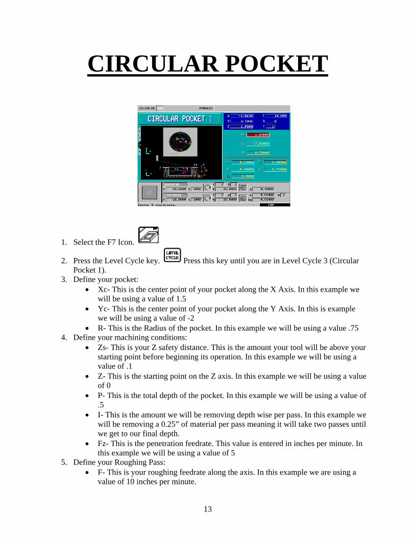
CIRCULAR POCKET
1. Select the F7 Icon.
2. Press the Level Cycle key. Press this key until you are in Level Cycle 3 (Circular Pocket 1).
3. Define your pocket: • Xc- This is the center point of your pocket along the X Axis. In this example we
will be using a value of 1.5 • Yc- This is the center point of your pocket along the Y Axis. In this is example
we will be using a value of -2 • R- This is the Radius of the pocket. In this example we will be using a value .75
4. Define your machining conditions: • Zs- This is your Z safety distance. This is the amount your tool will be above your
starting point before beginning its operation. In this example we will be using a value of .1
• Z- This is the starting point on the Z axis. In this example we will be using a value of 0
• P- This is the total depth of the pocket. In this example we will be using a value of .5
• I- This is the amount we will be removing depth wise per pass. In this example we will be removing a 0.25” of material per pass meaning it will take two passes until we get to our final depth.
• Fz- This is the penetration feedrate. This value is entered in inches per minute. In this example we will be using a value of 5
5. Define your Roughing Pass: • F- This is your roughing feedrate along the axis. In this example we are using a
value of 10 inches per minute.
13
• S- This is your spindle speed. In this example we are using a value of 1000 rpm.
• Select your spindle direction. To toggle between directions push the “half-key”. In this example we will be using a Clockwise Rotation.
• T- Enter is your tool number. In this example we are using T2. • D- Enter in your Tool Offset Number. In this example we are using D2. • This is your Sideways Penetration Angle. In this example we will penetrate
into the center of our pocket on a 30 Degree Angle. • This is the type of milling (Climb/Conventional Milling). • This is your step-over. In this example we will be using a value of .4
6. Define your Finishing Pass:
• F- This is your finishing feedrate. In this example we will be using a value of 10 inches per minute.
• S- This is your spindle speed. In this example we are using a value of 1000 rpm.
• Select your spindle direction. To toggle between directions push the “half-key”. In this example we will be using a Clockwise Rotation.
• T- Enter is your tool number. In this example we are using T2. • D- Enter in your Tool Offset Number. In this example we are using D2. • This is your Sideways Penetration Angle. In this example we will penetrate
into the center of our pocket on a 30 Degree Angle. • This is the type of milling (Climb/Conventional Milling). • This is the Finishing Pass. In this example we will be leaving 0.01 for the
finishing pass. • This is the Finishing Pass in Z. In this example we will be leaving 0.01 for the
finishing in Z. • This is the Number of Finishing Passes in Z. In this example we will be using
only 1 finishing pass.
14
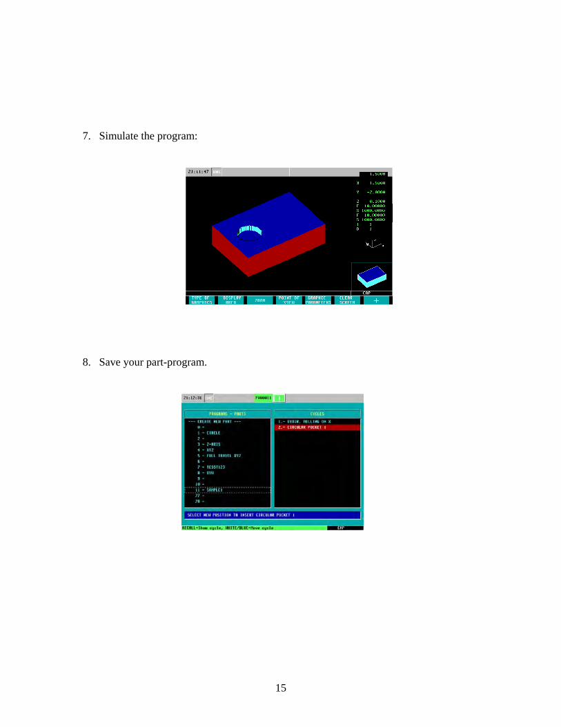
7. Simulate the program:
8. Save your part-program.
15
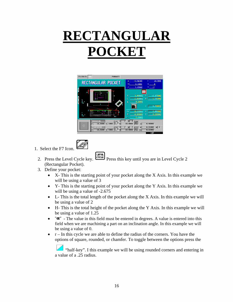
RECTANGULAR POCKET
1. Select the F7 Icon.
2. Press the Level Cycle key. Press this key until you are in Level Cycle 2 (Rectangular Pocket).
3. Define your pocket: • X- This is the starting point of your pocket along the X Axis. In this example we
will be using a value of 3 • Y- This is the starting point of your pocket along the Y Axis. In this example we
will be using a value of -2.675 • L- This is the total length of the pocket along the X Axis. In this example we will
be using a value of 2 • H- This is the total height of the pocket along the Y Axis. In this example we will
be using a value of 1.25 • - The value in this field must be entered in degrees. A value is entered into this
field when we are machining a part on an inclination angle. In this example we will be using a value of 0.
• r – In this cycle we are able to define the radius of the corners. You have the options of square, rounded, or chamfer. To toggle between the options press the
“half-key”. I this example we will be using rounded corners and entering in a value of a .25 radius.
16
4. Define your machining conditions: • Zs- This is your Z safety distance. This is the amount your tool will be above your
starting point before beginning its operation. In this example we will be using a value of 0.100”
• Z- This is the starting point on the Z axis. In this example we will be using a value of 0.
• P- This is the total depth of the pocket. In this example we will be using the value of 0.500”.
• I- This is the amount we will be removing depth wise per pass. In this example we will be removing a 0.250” of material per pass meaning it will take two passes until we get to our final depth.
• Fz- This is the penetration feedrate. This value is entered in inches per minute. In this example we will be using a value of 5.
5. Define your Roughing Pass: • F- This is your roughing feedrate along the axis. In this example we are using a
value of 10 inches per minute. • S- This is your spindle speed. In this example we are using a value of 1000 rpm.
• Select your spindle direction. To toggle between directions push the “half-key”. In this example we will be using a Clockwise Rotation.
• T- Enter is your tool number. In this example we are using T2. • D- Enter in your Tool Offset Number. In this example we are using D2. • This is your Sideways Penetration Angle. In this example we will penetrate
into the center of our pocket on a 30 Degree Angle. • This is the type of milling (Climb/Conventional Milling). • This is your step-over. In this example we will be using a value of .4
6. Define your Finishing Pass: • F- This is your finishing feedrate. In this example we will be using a value of 10
inches per minute. • S- This is your spindle speed. In this example we are using a value of 1000 rpm.
• Select your spindle direction. To toggle between directions push the “half-key”. In this example we will be using a Clockwise Rotation.
• T- Enter is your tool number. In this example we are using T2. • D- Enter in your Tool Offset Number. In this example we are using D2. • This is your Sideways Penetration Angle. In this example we will penetrate
into the center of our pocket on a 30 Degree Angle. • This is the type of milling (Climb/Conventional Milling). • This is the Finishing Pass. In this example we will be leaving 0.010” for the
finishing pass. • This is the Finishing Pass in Z. In this example we will be leaving .01 for the
finishing in Z.
17
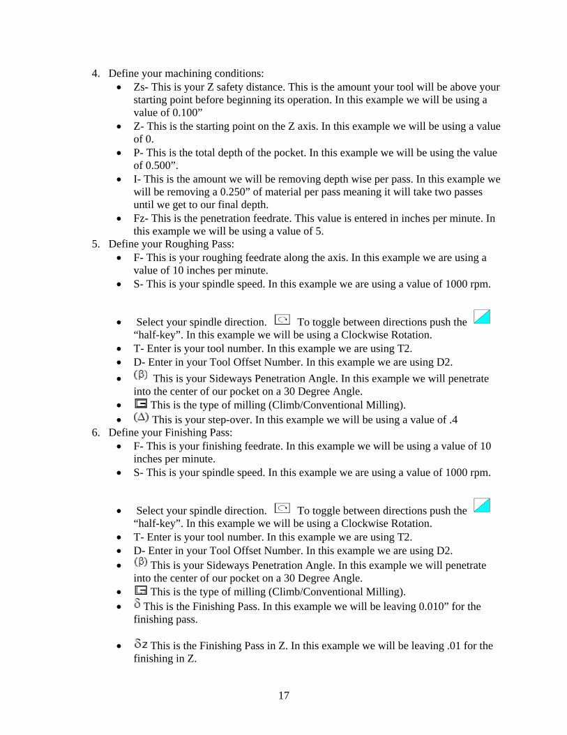
• This is the Number of Finishing Passes in Z. In this example we will be using only 1 finishing pass.
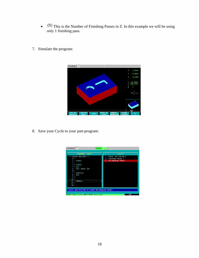
7. Simulate the program:
8. Save your Cycle to your part-program:
18
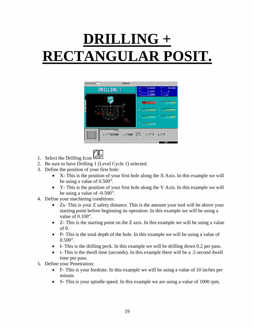
DRILLING + RECTANGULAR POSIT.
1. Select the Drilling Icon 2. Be sure to have Drilling 1 (Level Cycle 1) selected. 3. Define the position of your first hole:
• X- This is the position of your first hole along the X Axis. In this example we will be using a value of 0.500”.
• Y- This is the position of your first hole along the Y Axis. In this example we will be using a value of -0.500”.
4. Define your machining conditions: • Zs- This is your Z safety distance. This is the amount your tool will be above your
starting point before beginning its operation. In this example we will be using a value of 0.100”.
• Z- This is the starting point on the Z axis. In this example we will be using a value of 0.
• P- This is the total depth of the hole. In this example we will be using a value of 0.500”.
• I- This is the drilling peck. In this example we will be drilling down 0.2 per pass. • t- This is the dwell time (seconds). In this example there will be a .5 second dwell
time per pass. 5. Define your Penetration:
• F- This is your feedrate. In this example we will be using a value of 10 inches per minute.
• S- This is your spindle speed. In this example we are using a value of 1000 rpm.
19
• Select your spindle direction. To toggle between directions push the “half-key”. In this example we will be using a Clockwise Rotation.
• T- Enter is your tool number. In this example we are using T3. • D- Enter in your Tool Offset Number. In this example we are using D3.
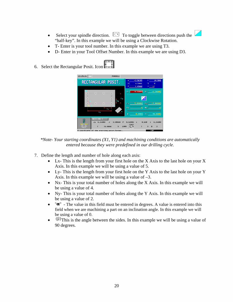
6. Select the Rectangular Posit. Icon
*Note- Your starting coordinates (X1, Y1) and machining conditions are automatically entered because they were predefined in our drilling cycle.
7. Define the length and number of hole along each axis:
• Lx- This is the length from your first hole on the X Axis to the last hole on your X Axis. In this example we will be using a value of 5.
• Ly- This is the length from your first hole on the Y Axis to the last hole on your Y Axis. In this example we will be using a value of –3.
• Nx- This is your total number of holes along the X Axis. In this example we will be using a value of 4.
• Ny- This is your total number of holes along the Y Axis. In this example we will be using a value of 2.
• - The value in this field must be entered in degrees. A value is entered into this field when we are machining a part on an inclination angle. In this example we will be using a value of 0.
• This is the angle between the sides. In this example we will be using a value of 90 degrees.
20
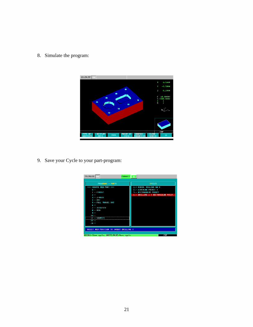
8. Simulate the program:
9. Save your Cycle to your part-program:
21
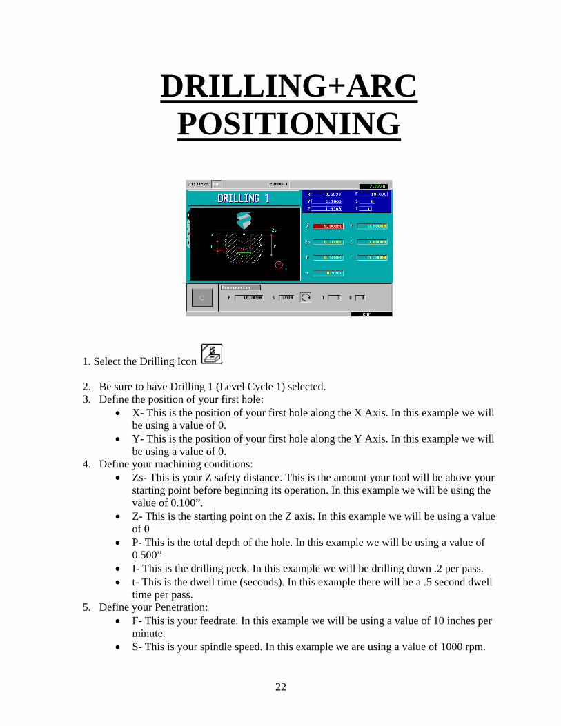
DRILLING+ARC POSITIONING
1. Select the Drilling Icon 2. Be sure to have Drilling 1 (Level Cycle 1) selected. 3. Define the position of your first hole:
• X- This is the position of your first hole along the X Axis. In this example we will be using a value of 0.
• Y- This is the position of your first hole along the Y Axis. In this example we will be using a value of 0.
4. Define your machining conditions: • Zs- This is your Z safety distance. This is the amount your tool will be above your
starting point before beginning its operation. In this example we will be using the value of 0.100”.
• Z- This is the starting point on the Z axis. In this example we will be using a value of 0
• P- This is the total depth of the hole. In this example we will be using a value of 0.500”
• I- This is the drilling peck. In this example we will be drilling down .2 per pass. • t- This is the dwell time (seconds). In this example there will be a .5 second dwell
time per pass. 5. Define your Penetration:
• F- This is your feedrate. In this example we will be using a value of 10 inches per minute.
• S- This is your spindle speed. In this example we are using a value of 1000 rpm.
22
• Select your spindle direction. To toggle between directions push the “half-key”. In this example we will be using a Clockwise Rotation.
• T- Enter is your tool number. In this example we are using T3. • D- Enter in your Tool Offset Number. In this example we are using D3.
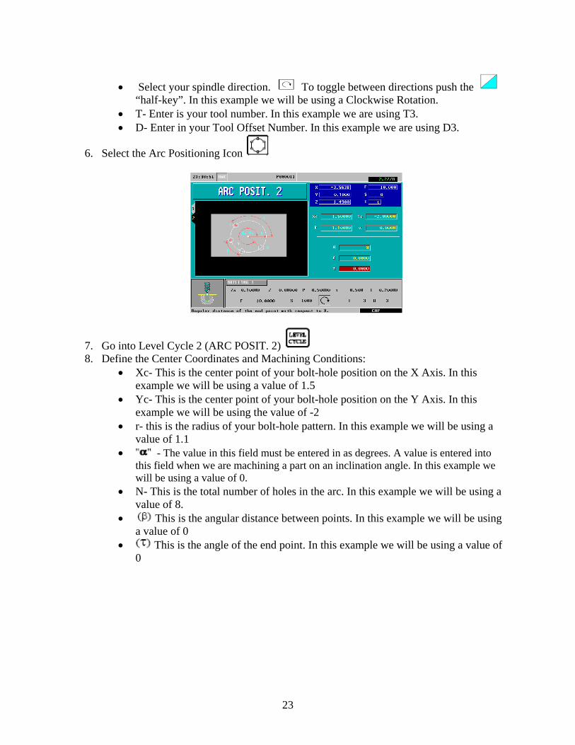
6. Select the Arc Positioning Icon
7. Go into Level Cycle 2 (ARC POSIT. 2) 8. Define the Center Coordinates and Machining Conditions:
• Xc- This is the center point of your bolt-hole position on the X Axis. In this example we will be using a value of 1.5
• Yc- This is the center point of your bolt-hole position on the Y Axis. In this example we will be using the value of -2
• r- this is the radius of your bolt-hole pattern. In this example we will be using a value of 1.1
• - The value in this field must be entered in as degrees. A value is entered into this field when we are machining a part on an inclination angle. In this example we will be using a value of 0.
• N- This is the total number of holes in the arc. In this example we will be using a value of 8.
• This is the angular distance between points. In this example we will be using a value of 0
• This is the angle of the end point. In this example we will be using a value of 0
23
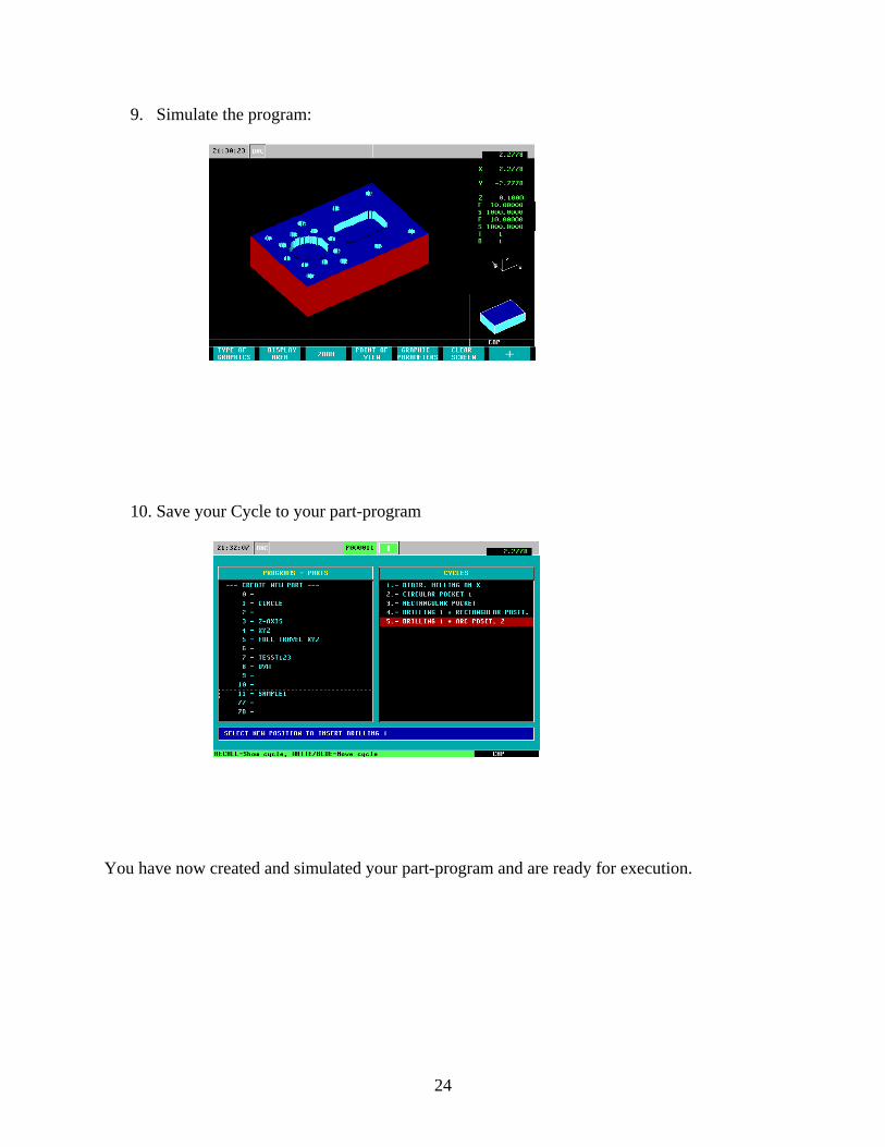
9. Simulate the program:
10. Save your Cycle to your part-program
You have now created and simulated your part-program and are ready for execution.
24

Miscellaneous Features
25
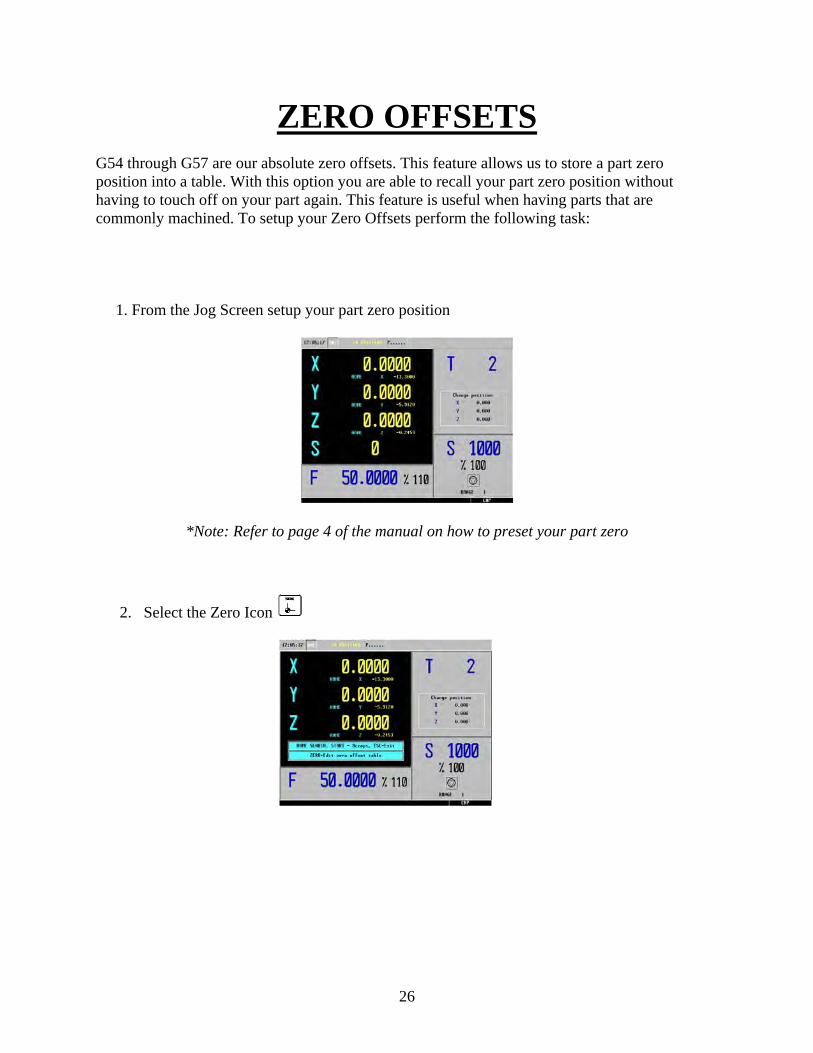
ZERO OFFSETS
G54 through G57 are our absolute zero offsets. This feature allows us to store a part zero position into a table. With this option you are able to recall your part zero position without having to touch off on your part again. This feature is useful when having parts that are commonly machined. To setup your Zero Offsets perform the following task: 1. From the Jog Screen setup your part zero position
*Note: Refer to page 4 of the manual on how to preset your part zero
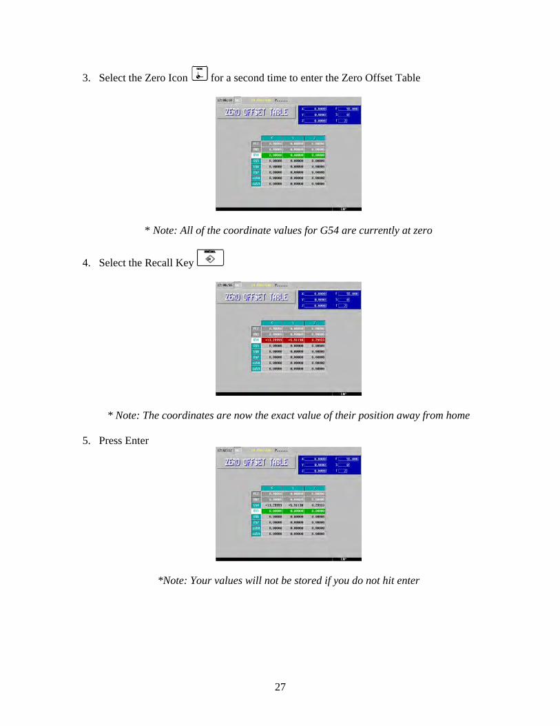
2. Select the Zero Icon
26
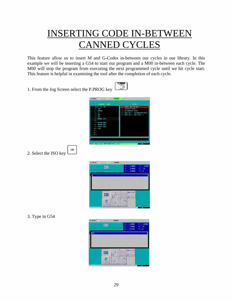
3. Select the Zero Icon for a second time to enter the Zero Offset Table
* Note: All of the coordinate values for G54 are currently at zero
4. Select the Recall Key
* Note: The coordinates are now the exact value of their position away from home 5. Press Enter
*Note: Your values will not be stored if you do not hit enter
27

ISO MODE The ISO key gives you access to the MDI Mode. What this feature allows you to do is perform one or more functions at a time. It allows you to move more than one axes at a time, start the spindle, set the feed, insert G-Codes, etc. To operate in ISO Mode, execute the following instructions:
1. From the Jog Screen select the ISO key
• In this example we will be turning on the spindle at a clockwise rotation at 100 rpm’s
• The CNC will display a red window at the bottom of the screen
2. Type in S100 M3
3. Press Cycle Start
*Note: The spindle speed has changed to 100 and the icon has changed to a clock-wise position.
28
INSERTING CODE IN-BETWEEN CANNED CYCLES
This feature allow us to insert M and G-Codes in-between our cycles in our library. In this example we will be inserting a G54 to start our program and a M00 in-between each cycle. The M00 will stop the program from executing the next programmed cycle until we hit cycle start. This feature is helpful in examining the tool after the completion of each cycle.
1. From the Jog Screen select the P.PROG key
2. Select the ISO key
3. Type in G54
29
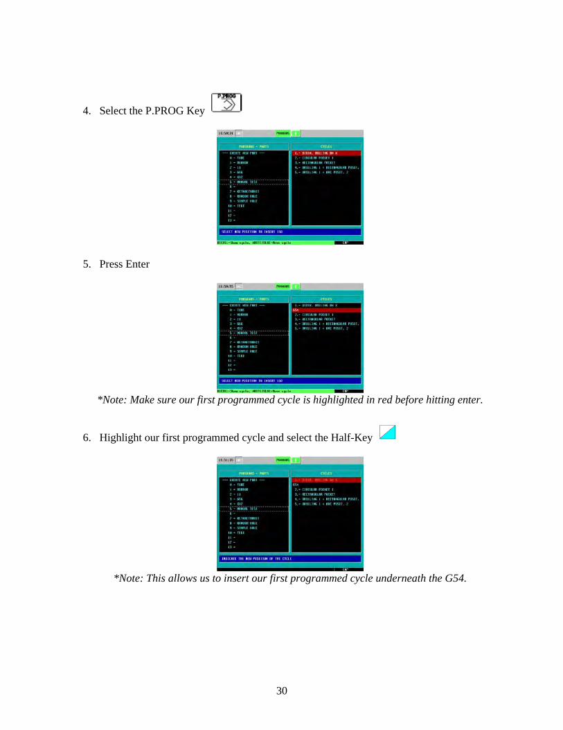
4. Select the P.PROG Key
5. Press Enter
*Note: Make sure our first programmed cycle is highlighted in red before hitting enter.
6. Highlight our first programmed cycle and select the Half-Key
*Note: This allows us to insert our first programmed cycle underneath the G54.
30
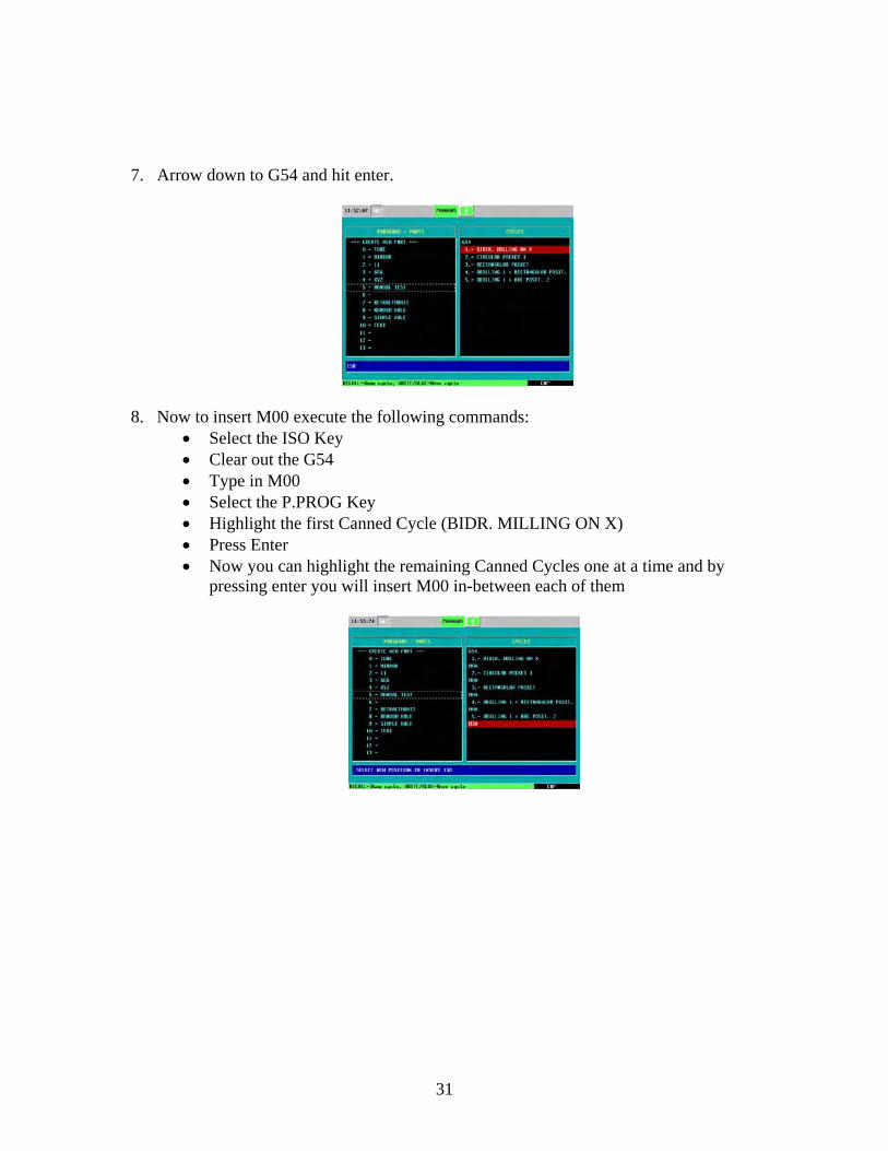
7. Arrow down to G54 and hit enter.
8. Now to insert M00 execute the following commands:
• Select the ISO Key • Clear out the G54 • Type in M00 • Select the P.PROG Key • Highlight the first Canned Cycle (BIDR. MILLING ON X) • Press Enter • Now you can highlight the remaining Canned Cycles one at a time and by
pressing enter you will insert M00 in-between each of them
31
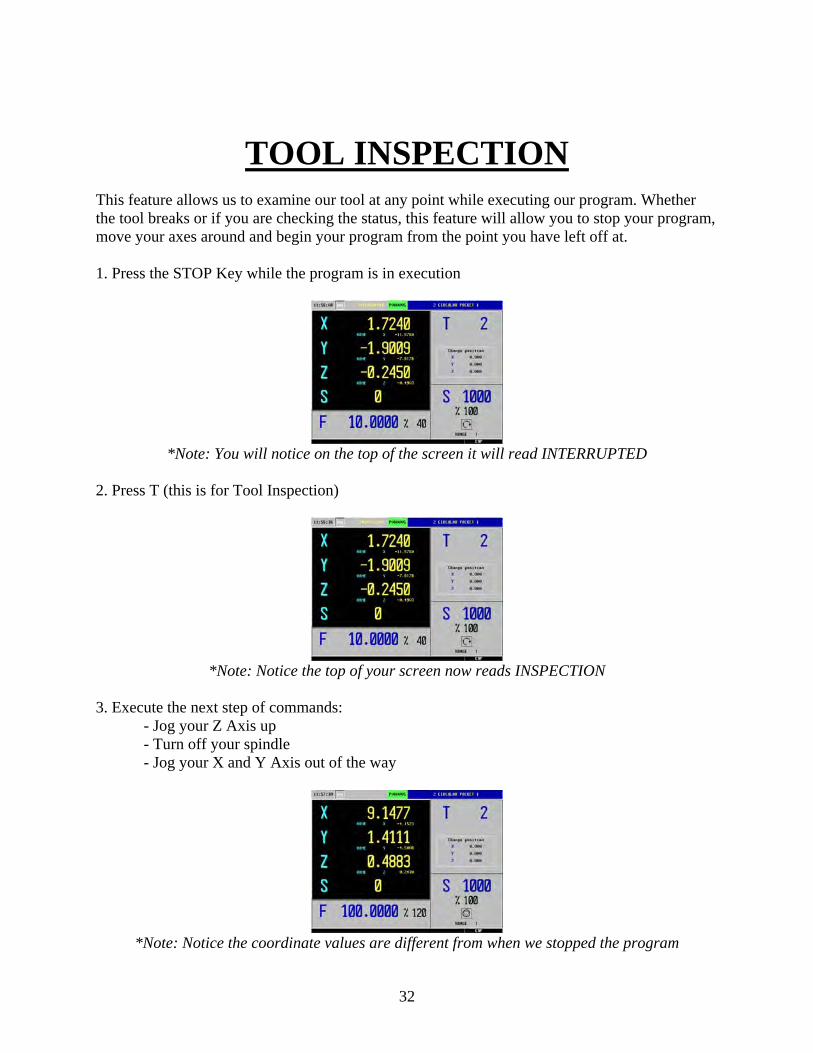
TOOL INSPECTION This feature allows us to examine our tool at any point while executing our program. Whether the tool breaks or if you are checking the status, this feature will allow you to stop your program, move your axes around and begin your program from the point you have left off at. 1. Press the STOP Key while the program is in execution
*Note: You will notice on the top of the screen it will read INTERRUPTED
2. Press T (this is for Tool Inspection)
*Note: Notice the top of your screen now reads INSPECTION
3. Execute the next step of commands: - Jog your Z Axis up - Turn off your spindle - Jog your X and Y Axis out of the way
*Note: Notice the coordinate values are different from when we stopped the program
32
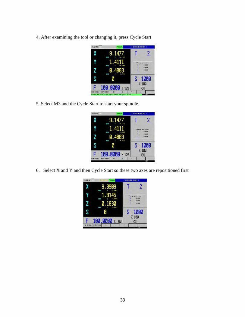
4. After examining the tool or changing it, press Cycle Start
5. Select M3 and the Cycle Start to start your spindle
6. Select X and Y and then Cycle Start so these two axes are repositioned first
33
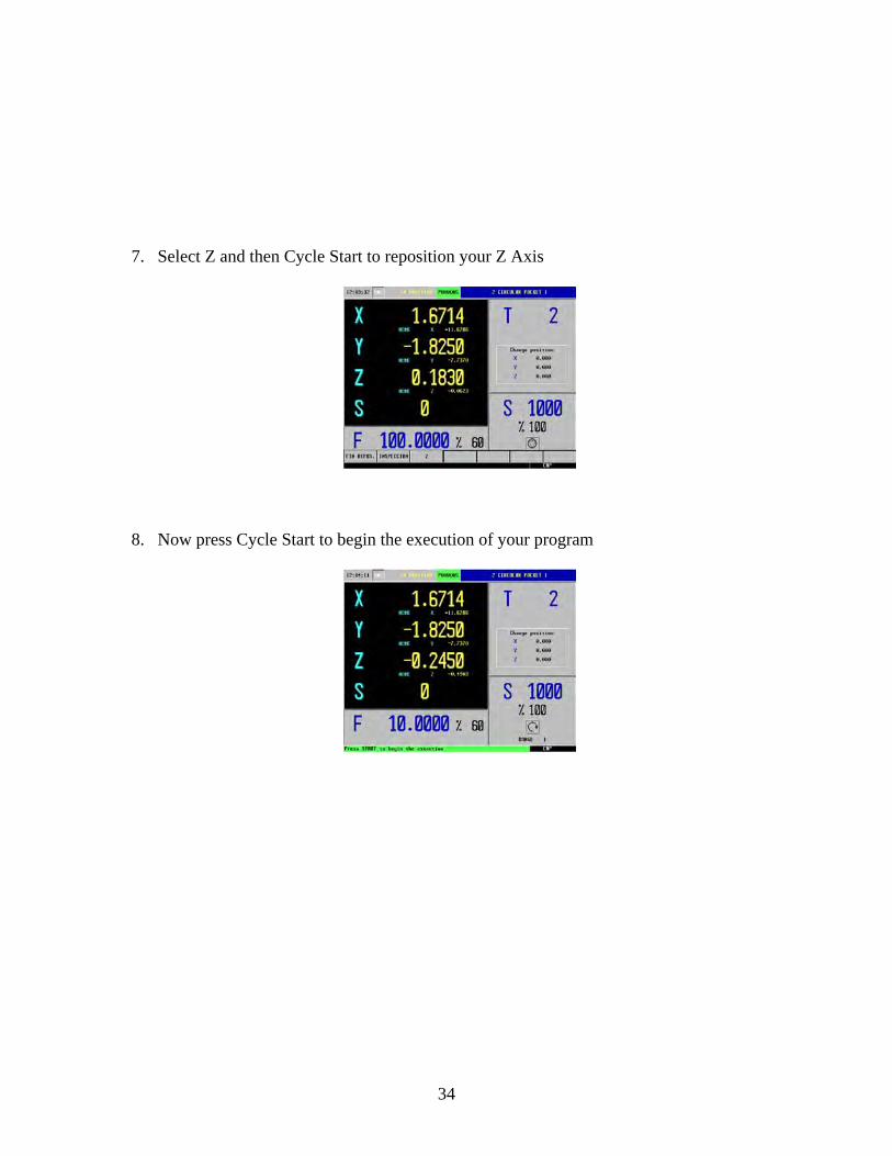
7. Select Z and then Cycle Start to reposition your Z Axis
8. Now press Cycle Start to begin the execution of your program
34
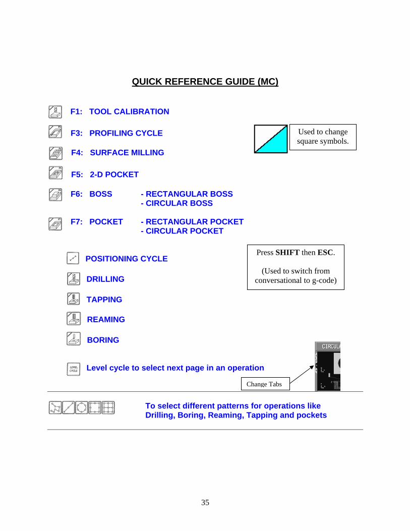
QUICK REFERENCE GUIDE (MC)
F1: TOOL CALIBRATION
Used to change square symbols.
F3: PROFILING CYCLE F4: SURFACE MILLING F5: 2-D POCKET F6: BOSS - RECTANGULAR BOSS
- CIRCULAR BOSS
F7: POCKET - RECTANGULAR POCKET - CIRCULAR POCKET
Press SHIFT then ESC.
(Used to switch from
conversational to g-code)
POSITIONING CYCLE DRILLING TAPPING REAMING BORING
Level cycle to select next page in an operation
Change Tabs
To select different patterns for operations like
Drilling, Boring, Reaming, Tapping and pockets
35
36
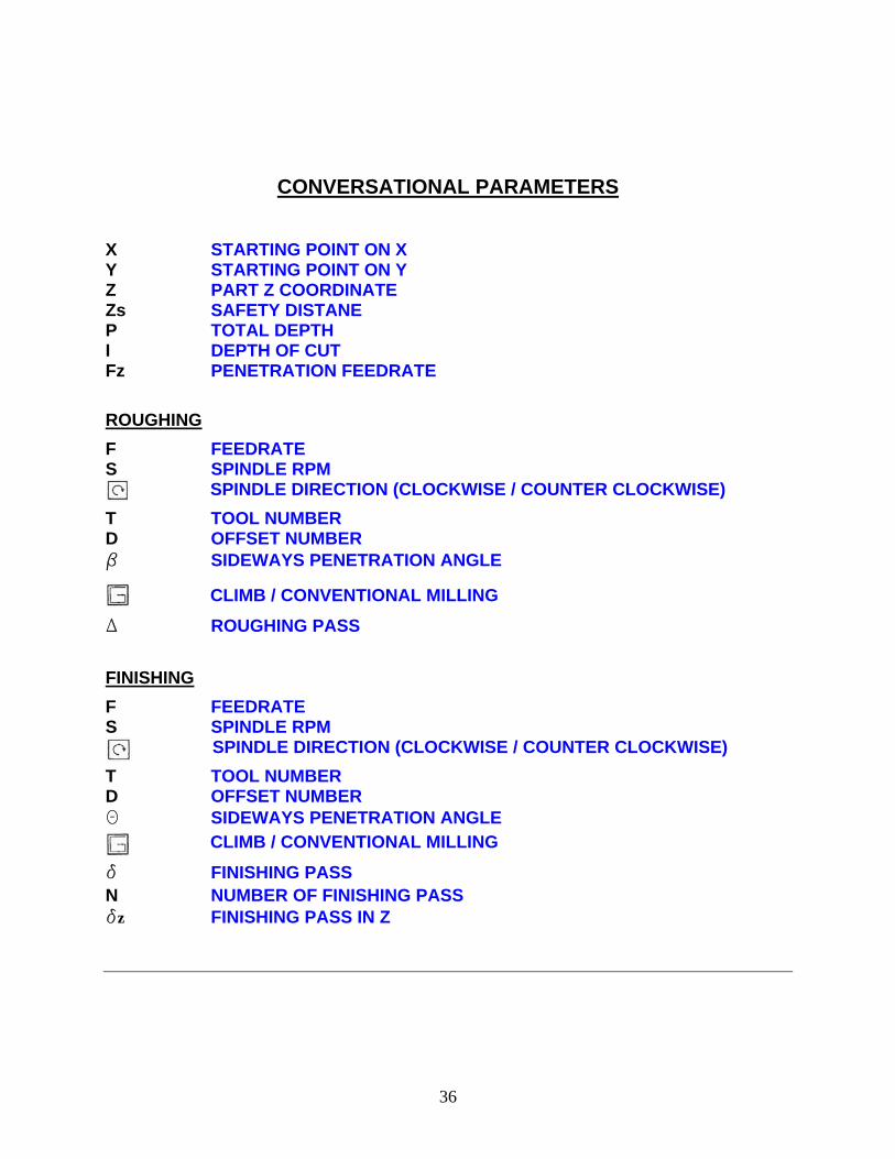
CONVERSATIONAL PARAMETERS
X STARTING POINT ON X Y STARTING POINT ON Y Z PART Z COORDINATE Zs SAFETY DISTANE P TOTAL DEPTH I DEPTH OF CUT Fz PENETRATION FEEDRATE ROUGHING F FEEDRATE S SPINDLE RPM
SPINDLE DIRECTION (CLOCKWISE / COUNTER CLOCKWISE) T TOOL NUMBER D OFFSET NUMBER b SIDEWAYS PENETRATION ANGLE
CLIMB / CONVENTIONAL MILLING
D ROUGHING PASS FINISHING F FEEDRATE S SPINDLE RPM
SPINDLE DIRECTION (CLOCKWISE / COUNTER CLOCKWISE) T TOOL NUMBER D OFFSET NUMBER Q SIDEWAYS PENETRATION ANGLE
CLIMB / CONVENTIONAL MILLING
d FINISHING PASS N NUMBER OF FINISHING PASS dz FINISHING PASS IN Z