Embed Size (px)
Citation preview
XAPP1271 (v2.0) March 24, 2017 1www.xilinx.com
SummaryThis application note demonstrates the implementation of the DisplayPort TX and RX Subsystems (two byte and four byte mode) and Video_PHY_Controller system IPs that includes policy maker features and a DisplayPort controller on a single GT quad. Three hardware designs (Tcl files) and one MST design are provided with this reference design separately for Single Stream Transport (SST) mode of operation. Video received by the DisplayPort RX Subsystem is sent over to the DisplayPort TX Subsystem. The reference design is created and built using the Vivado Design Suite. Instructions are included for building the hardware, building the software with local drivers for DisplayPort, and testing the design on the Xilinx KC705, KCU105 boards with the generated bitstream and Executable Linker format (ELF) files.
In addition, the ready_for_download folder in the package contains the ready-made tested bitstreams and elf files for SST mode.The Tcl file provided under the hardware folder can be executed in the Vivado design tools to create the project and generate the bitstream. The Software Development Kit (SDK) workspace that contains the source code and BSP folder that can be re-built to create the elf file is provided under the software directory. This application note also demonstrates the implementation of the DisplayPort RX subsystem in the Multi-Stream Transport (MST) mode.
ObjectiveThis application note describes how to implement the DisplayPort TX and RX Subsystem cores to transmit and receive using the vid_phy_controller IP. It also explains how to bring up the source/sink core through the following initialization steps:
• Configuring the GTs using vid_phy_controller
• Training the main link
• Setting up the source/sink core registers
• Monitoring and taking appropriate action on cable plug and unplug
It showcases a system by receiving video over DisplayPort using the Xilinx DisplayPort RX Subsystem and then transporting same video data using the Xilinx DisplayPort TX Subsystem core to a DisplayPort capable monitor for SST (DisplayPort Pass-Through (DPPT)). These solutions are implemented on KC705 and KCU105 evaluation boards.
Application Note: Kintex-7 and Kintex UltraScale Families
XAPP1271 (v2.0) March 24, 2017
DisplayPort Pass-Through Reference Design for SST and MST Modes Using Video PHY ControllerKei Ito
Requirements
XAPP1271 (v2.0) March 24, 2017 2www.xilinx.com
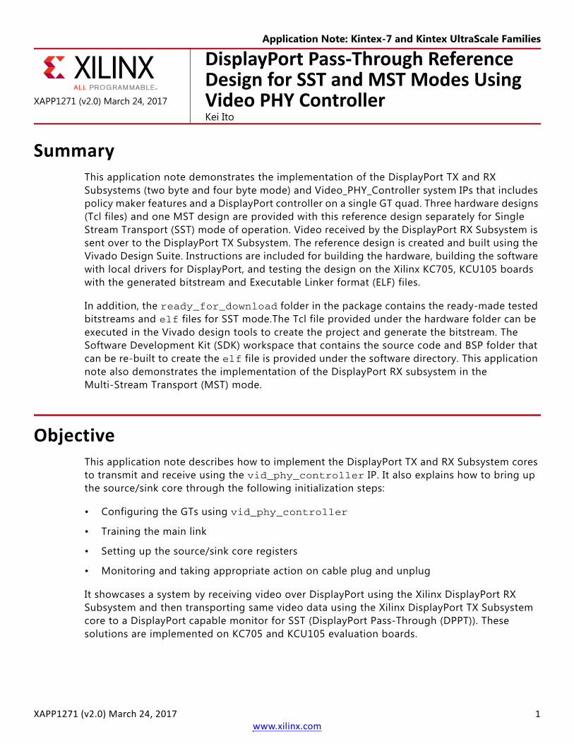
This application note contains a total of four designs. They include the following:
1. One SST design for KC705 board four byte.
2. One SST design for KC705 board two byte with HDCP.
3. One MST RX design for KC705 board two byte.
4. One SST design for KCU105 board two byte.
Requirements
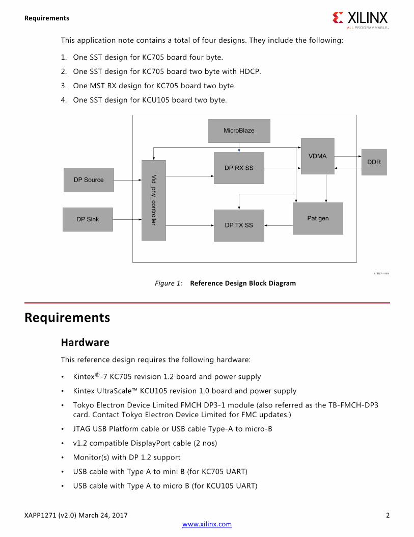
HardwareThis reference design requires the following hardware:
• Kintex®-7 KC705 revision 1.2 board and power supply
• Kintex UltraScale™ KCU105 revision 1.0 board and power supply
• Tokyo Electron Device Limited FMCH DP3-1 module (also referred as the TB-FMCH-DP3 card. Contact Tokyo Electron Device Limited for FMC updates.)
• JTAG USB Platform cable or USB cable Type-A to micro-B
• v1.2 compatible DisplayPort cable (2 nos)
• Monitor(s) with DP 1.2 support
• USB cable with Type A to mini B (for KC705 UART)
• USB cable with Type A to micro B (for KCU105 UART)
X-Ref Target - Figure 1
Figure 1: Reference Design Block Diagram
DP Source
DP Sink
MicroBlaze
DP RX SS
Vid_phy_controller DP TX SS
VDMA
Pat gen
DDR
X15627-111016

Requirements
XAPP1271 (v2.0) March 24, 2017 3www.xilinx.com
• DisplayPort 1.2 capable source to drive the Sink. When using the RX MST system ensure that the source is capable of sending the MST stream.
Software• Xilinx Vivado Design Suite 2016.4
• Xilinx Software Development Kit 2016.4
• Tera Term/putty terminal emulator for UART serial communication through a COM port
Package DetailsThis section shows the directory structure of the design files provided along with the application note. All files are in the DPPT_Xapp directory. The user directory path under which this DPPT_Xapp is copied to is being referred as XAPP1271 in the rest of this application note.
Figure 2 shows the directory structure for KC705 based solution. Same structure is applicable to KCU105 board too.
You can download the Reference Design Files for this application note from the Xilinx website.
X-Ref Target - Figure 2
Figure 2: Reference Design Directory Structure
Features
XAPP1271 (v2.0) March 24, 2017 4www.xilinx.com
• hdcp_util: This directory contains the utility hardware and software needed to program the HDCP keys into EEPROM.
• repo: This directory contains the local IPs and drivers needed to implement the hardware and software.
• kc705: This directory contains all the scripts and sources needed to build the systems on KC705 evaluation board. This directory contains two subdirectories sst and mst.
• kcu105: This directory contains all the scripts and sources needed to build the systems on KCU105 evaluation board. This directory contains one subdirectory sst and that contains system_3.
This directory contains a total of four designs. They include the following:
1. For \kc705\sst\system_4, one SST design for KC705 board four byte.
2. For \kc705\sst\system_1, one SST design for KC705 board two byte with HDCP.
3. For \kc705\mst\rx, one MST RX design for KC705 board two byte.
4. For \kc105\sst\system_3, one SST design for KCU105 board two byte.
Each subdirectory has its own hw and sw folders which contain the scripts to generate the system and SDK workspace.
Although the DisplayPort subsystems support up to 16 bits per color (BPC), the SST systems are created to support a maximum of 10 BPC.
The ready_to_download folders contain the bit and elf files that can be used directly on KC705 evaluation board.
The mst folder contains the rx mst system.
FeaturesThe reference design includes the following features:
• Dynamic reference clock selection
• Designed with the VESA DisplayPort Specification v1.2
• Switchable lane rates: 1.62, 2.7, or 5.4 Gb/s
• Variable lanes: 1, 2, or 4 lanes
Hardware Block DiagramFigure 3 shows the hardware architecture of the reference design. The design uses the Vivado Design Suite IP integrator tool, a block-based design, and assembly tool. The IP integrator is used to integrate many of the key blocks of the design into a subsystem.

Features
XAPP1271 (v2.0) March 24, 2017 5www.xilinx.com
The IP integrator block diagram consists of the MicroBlaze™ processor, AXI interconnect IP, MIG 7 series IP (for KC705) or DDR4 IP (for KCU105), and other AXI4-Lite peripherals.
The IP integrator subsystem is integrated in the top module along with DisplayPort IP and custom design sources for video pattern generator and video clock generator. The MicroBlaze processor changes the DisplayPort core configuration over the AXI4-Lite interface based on the user application.
ClockingThe DPPT system uses the following clock:
• MicroBlaze and all the peripheral interfaces (AXI4-Lite) run at 100 MHz clock. This is derived from the MIG for KC705 and DDR4 for KCU105.
• The TED FMCH DP3-1 provides two clocks for DP operation. Refclk 0 is generated with the on-board clock generator. Refclk 1 is an output of the TI DP159 retimer.
• A transmit video clock is generated using MMCM. It is derived from the 100 MHz clock that is an output by MIG/DDR4.
• The receiver video clock is fixed at 200 MHz and is derived from MIG/DDR4.
X-Ref Target - Figure 3
Figure 3: Hardware Block Diagram
DDR
MicroBlaze
AXI Timer
IntrController
AXIUartLite
Proc SysReset
AX
I Interconnect
Vid Clk
DP RX SS
DP TX SS
PAT GEN
Vid PH
Y Controller
AX
IInterC
onnect
AXI VDMA
MIG
DP Source
DP Sink
Refclk 0Refclk 1
UART
X15640-111016
Features
XAPP1271 (v2.0) March 24, 2017 6www.xilinx.com
Pattern GeneratorA video pattern generator is provided in the system to generate video on the TX link. This pattern generator is capable of generating seven test video patterns as follows:
• Vesa logical Link control (LLC) pattern
• Vesa pattern three bars
• Vesa color squares
• Flat red
• Flat blue
• Flat green
• Flat purple
Alternatively, this pattern generator also allows feeding any user video that is connected to its input.
DPPT System InitializationThe MicroBlaze processor interfaces with the DisplayPort Subsystem, vid_phy_controller and other cores through the AXI4-Lite interface. This enables the software application and policy maker to perform the PHY initialization, DisplayPort initialization, initiate and maintain the main link through register writes and reads. This reference design customizes the DisplayPort Subsystem cores to work as receive and transmit, Max Bits per color of 10, Quad pixel enable, Max number of lanes as 4, and Max Link rate of 5.4 Gb/s. The physical layer (PHY) is customized using the vid_phy_controller. The eighth transceivers, four each for TX and RX, are mapped to the four GTX (or GTHE3) transceivers in the FMC HPC on the KC705 (or KCU105) board.
Software ApplicationThe reference design includes a software application running on a MicroBlaze processor to initialize and maintain the DisplayPort link. The software application uses the DisplayPort and DisplayPort Subsystem drivers provided with the Vivado Design Suite 2016.4 installation. The Subsystem drivers perform the task of link training by taking care of TI DP159 programming. This application primarily demonstrates the capabilities of vid_phy_controller and DisplayPort RX/TX Subsystems. This application provides an interactive UART console through which you can test the system at different modes of operation.
Features
XAPP1271 (v2.0) March 24, 2017 7www.xilinx.com
X-Ref Target - Figure 4
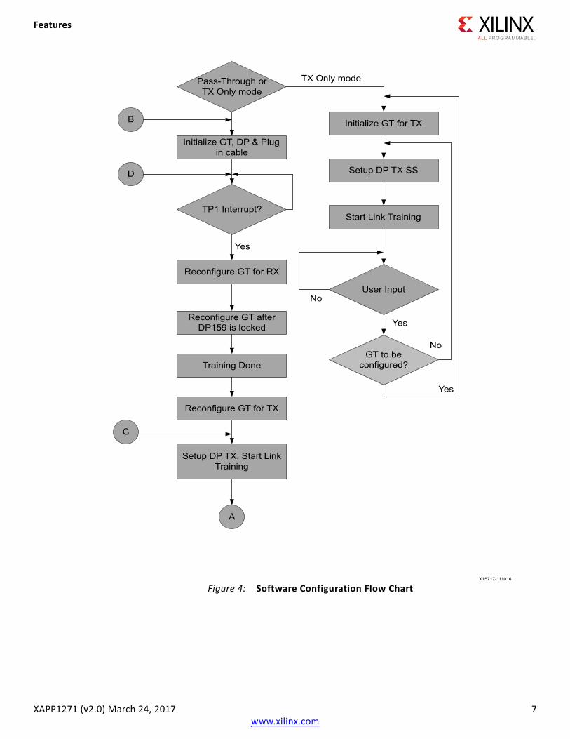
Figure 4: Software Configuration Flow Chart
Pass-Through or TX Only mode
Initialize GT, DP & Plug in cable
TP1 Interrupt?
Reconfigure GT for RX
Reconfigure GT after DP159 is locked
Training Done
Reconfigure GT for TX
Setup DP TX, Start LinkTraining
B
D
C
A
Initialize GT for TX
Setup DP TX SS
Start Link Training
User Input
GT to be configured?
No
No
Yes
Yes
Yes
TX Only mode
X15717-111016
Features
XAPP1271 (v2.0) March 24, 2017 8www.xilinx.com
Initialization and Application FlowYou have to choose between a Transmit Only mode (option t) or a Pass-Through mode (option r or s) to start the application. Based on the option selected, the application configures the GT and DisplayPort Subsystems. The DisplayPort receiver (Sink or RX) always uses CPLL while Transmitter (Source or TX) can use CPLL or QPLL. The selection between QPLL or CPLL is done based on the device.
X-Ref Target - Figure 5
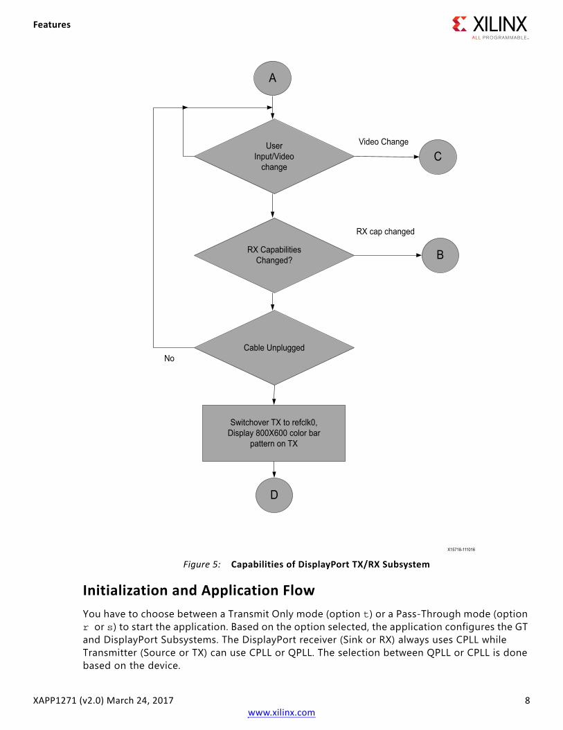
Figure 5: Capabilities of DisplayPort TX/RX Subsystem
UserInput/Video
change
RX CapabilitiesChanged?
Cable Unplugged
A
C
B
D
Switchover TX to refclk0,Display 800X600 color bar
pattern on TX
No
RX cap changed
Video Change
X15718-111016
Features
XAPP1271 (v2.0) March 24, 2017 9www.xilinx.com
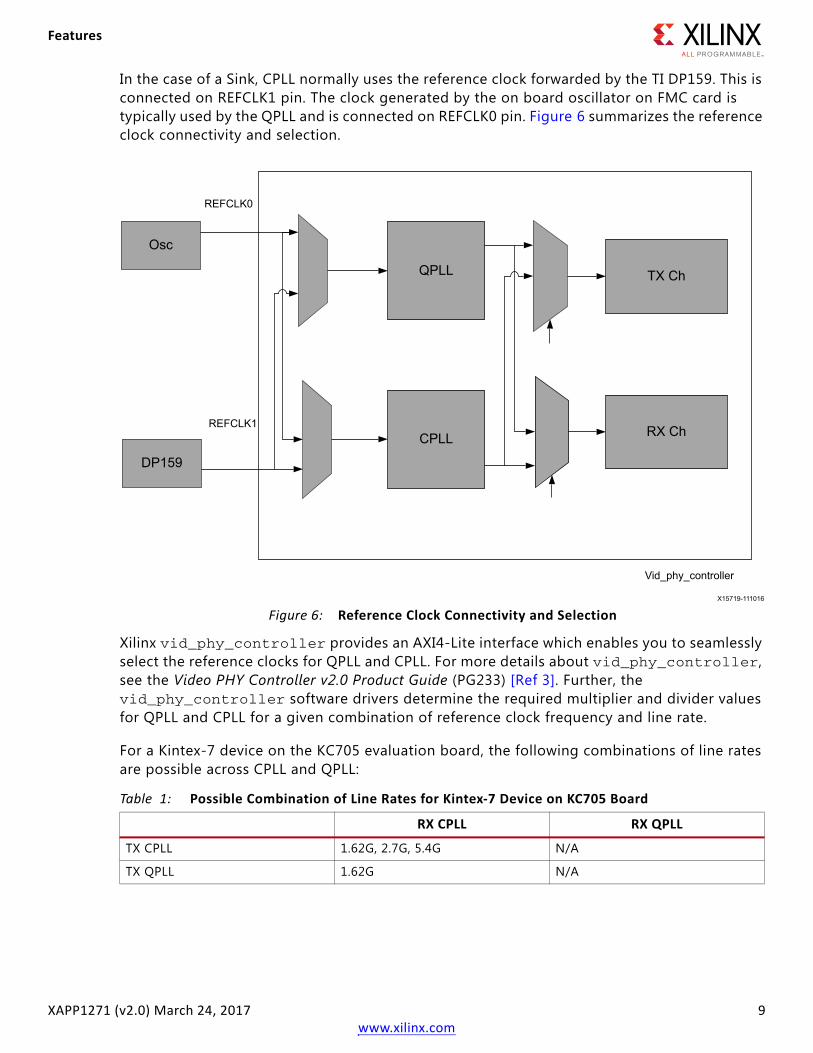
In the case of a Sink, CPLL normally uses the reference clock forwarded by the TI DP159. This is connected on REFCLK1 pin. The clock generated by the on board oscillator on FMC card is typically used by the QPLL and is connected on REFCLK0 pin. Figure 6 summarizes the reference clock connectivity and selection.
Xilinx vid_phy_controller provides an AXI4-Lite interface which enables you to seamlessly select the reference clocks for QPLL and CPLL. For more details about vid_phy_controller, see the Video PHY Controller v2.0 Product Guide (PG233) [Ref 3]. Further, the vid_phy_controller software drivers determine the required multiplier and divider values for QPLL and CPLL for a given combination of reference clock frequency and line rate.
For a Kintex-7 device on the KC705 evaluation board, the following combinations of line rates are possible across CPLL and QPLL:
X-Ref Target - Figure 6
Figure 6: Reference Clock Connectivity and Selection
Table 1: Possible Combination of Line Rates for Kintex-7 Device on KC705 Board
RX CPLL RX QPLL
TX CPLL 1.62G, 2.7G, 5.4G N/A
TX QPLL 1.62G N/A
QPLL
CPLL
TX Ch
RX Ch
Osc
DP159
REFCLK0
REFCLK1
Vid_phy_controller
X15719-111016
Features
XAPP1271 (v2.0) March 24, 2017 10www.xilinx.com
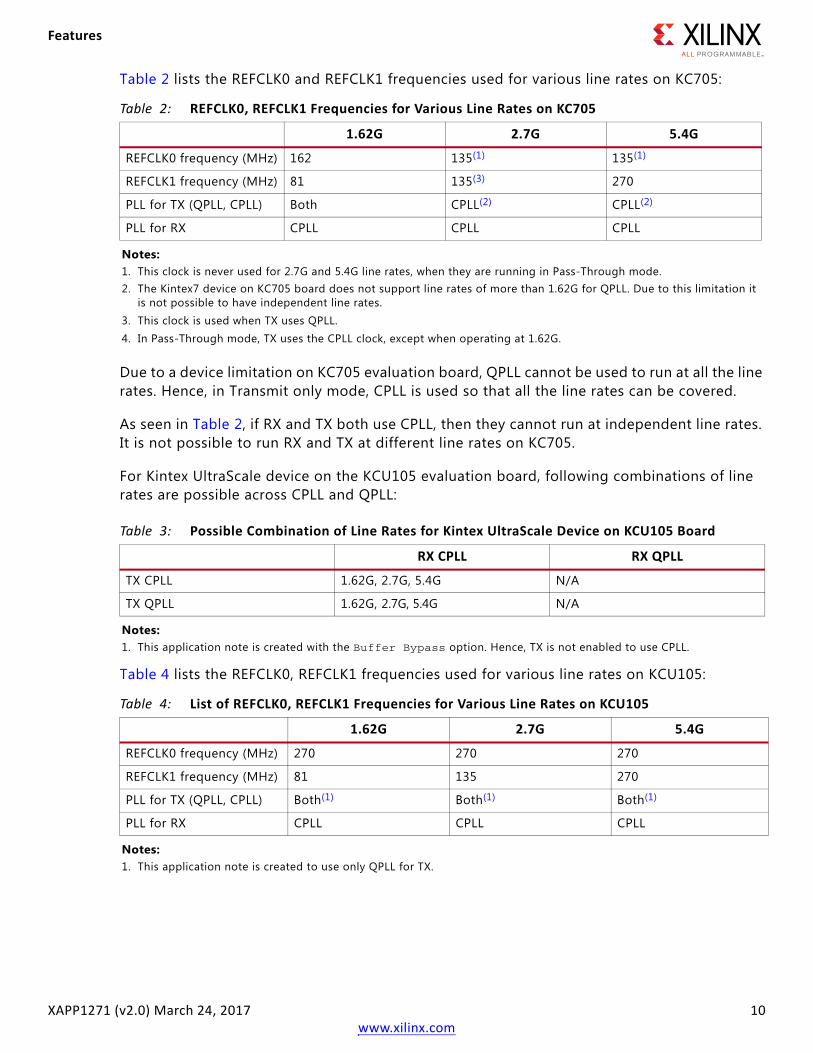
Table 2 lists the REFCLK0 and REFCLK1 frequencies used for various line rates on KC705:
Due to a device limitation on KC705 evaluation board, QPLL cannot be used to run at all the line rates. Hence, in Transmit only mode, CPLL is used so that all the line rates can be covered.
As seen in Table 2, if RX and TX both use CPLL, then they cannot run at independent line rates. It is not possible to run RX and TX at different line rates on KC705.
For Kintex UltraScale device on the KCU105 evaluation board, following combinations of line rates are possible across CPLL and QPLL:
Table 4 lists the REFCLK0, REFCLK1 frequencies used for various line rates on KCU105:
Table 2: REFCLK0, REFCLK1 Frequencies for Various Line Rates on KC705
1.62G 2.7G 5.4G
REFCLK0 frequency (MHz) 162 135(1) 135(1)
REFCLK1 frequency (MHz) 81 135(3) 270
PLL for TX (QPLL, CPLL) Both CPLL(2) CPLL(2)
PLL for RX CPLL CPLL CPLL
Notes: 1. This clock is never used for 2.7G and 5.4G line rates, when they are running in Pass-Through mode.2. The Kintex7 device on KC705 board does not support line rates of more than 1.62G for QPLL. Due to this limitation it
is not possible to have independent line rates.3. This clock is used when TX uses QPLL.4. In Pass-Through mode, TX uses the CPLL clock, except when operating at 1.62G.
Table 3: Possible Combination of Line Rates for Kintex UltraScale Device on KCU105 Board
RX CPLL RX QPLL
TX CPLL 1.62G, 2.7G, 5.4G N/A
TX QPLL 1.62G, 2.7G, 5.4G N/A
Notes: 1. This application note is created with the Buffer Bypass option. Hence, TX is not enabled to use CPLL.
Table 4: List of REFCLK0, REFCLK1 Frequencies for Various Line Rates on KCU105
1.62G 2.7G 5.4G
REFCLK0 frequency (MHz) 270 270 270
REFCLK1 frequency (MHz) 81 135 270
PLL for TX (QPLL, CPLL) Both(1) Both(1) Both(1)
PLL for RX CPLL CPLL CPLL
Notes: 1. This application note is created to use only QPLL for TX.
Features
XAPP1271 (v2.0) March 24, 2017 11www.xilinx.com
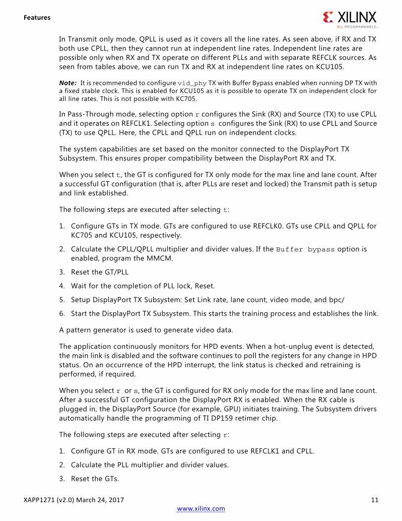
In Transmit only mode, QPLL is used as it covers all the line rates. As seen above, if RX and TX both use CPLL, then they cannot run at independent line rates. Independent line rates are possible only when RX and TX operate on different PLLs and with separate REFCLK sources. As seen from tables above, we can run TX and RX at independent line rates on KCU105.
Note: It is recommended to configure vid_phy TX with Buffer Bypass enabled when running DP TX with a fixed stable clock. This is enabled for KCU105 as it is possible to operate TX on independent clock for all line rates. This is not possible with KC705.
In Pass-Through mode, selecting option r configures the Sink (RX) and Source (TX) to use CPLL and it operates on REFCLK1. Selecting option s configures the Sink (RX) to use CPLL and Source (TX) to use QPLL. Here, the CPLL and QPLL run on independent clocks.
The system capabilities are set based on the monitor connected to the DisplayPort TX Subsystem. This ensures proper compatibility between the DisplayPort RX and TX.
When you select t, the GT is configured for TX only mode for the max line and lane count. After a successful GT configuration (that is, after PLLs are reset and locked) the Transmit path is setup and link established.
The following steps are executed after selecting t:
1. Configure GTs in TX mode. GTs are configured to use REFCLK0. GTs use CPLL and QPLL for KC705 and KCU105, respectively.
2. Calculate the CPLL/QPLL multiplier and divider values. If the Buffer bypass option is enabled, program the MMCM.
3. Reset the GT/PLL
4. Wait for the completion of PLL lock, Reset.
5. Setup DisplayPort TX Subsystem: Set Link rate, lane count, video mode, and bpc/
6. Start the DisplayPort TX Subsystem. This starts the training process and establishes the link.
A pattern generator is used to generate video data.
The application continuously monitors for HPD events. When a hot-unplug event is detected, the main link is disabled and the software continues to poll the registers for any change in HPD status. On an occurrence of the HPD interrupt, the link status is checked and retraining is performed, if required.
When you select r or s, the GT is configured for RX only mode for the max line and lane count. After a successful GT configuration the DisplayPort RX is enabled. When the RX cable is plugged in, the DisplayPort Source (for example, GPU) initiates training. The Subsystem drivers automatically handle the programming of TI DP159 retimer chip.
The following steps are executed after selecting r:
1. Configure GT in RX mode. GTs are configured to use REFCLK1 and CPLL.
2. Calculate the PLL multiplier and divider values.
3. Reset the GTs.
Features
XAPP1271 (v2.0) March 24, 2017 12www.xilinx.com
4. When the GPU initiates training, a TP1 interrupt is generated as part of training. The Subsystem drivers automatically handle the DP159 programming.
5. After a successful DP159 programming, clock is available on REFCLK1 pin. GT may be needed to be reconfigured based on the bandwidth set.
6. Reset the GT/PLL.
7. After the Training is completed, DisplayPort RX Subsystem receives the video.
8. The DisplayPort TX Subsystem is now set up by configuring the GTs for transmit path.
a. When you select r, the TX path uses the same CPLL.
b. When you select s, the TX path is configured to use QPLL.
AXI VDMA is used to store/buffer the video that is received by RX Subsystem. The same video is then sent over the TX path. After a successful link training the Xilinx DisplayPort Sink is detected as monitor by the host machine. The application continuously monitors the RX link for any change in video format, resolution, or BPC. The transmit path is restarted when change is detected on any of the above parameters. This ensures that the TX always displays the correct Video. In the case of RX cable unplug event, the TX is switched over to display a constant color bar pattern of 800x600 resolution.
MST Systems
For RX MST system, the DisplayPort RX Subsystem is configured in MST mode while the TX Subsystem is configured in SST mode to display the video of each stream. You can select the video stream to be displayed on TX by choosing the appropriate option in the UART menu.
Note: This application note does not cover the details of DisplayPort link training and other aspects such as AUX link.
HDCP Support and OperationThe systems come with optional HDCP support. HDCP is supported by both, the DP RX Subsystem as well as the DP TX Subsystem (SST mode only). This application note provides two systems; one with HDCP and the other without HDCP.
Note: To have a working HDCP solution it is necessary to have valid HDCP keys and a monitor that supports HDCP. Xilinx does not provide any HDCP keys. See Configuring HDCP Keys and Key Management, page 30 to setup and manage HDCP Keys.
The application detects the HDCP capabilities of the monitor that is connected to DP TX Subsystem. HDCP feature is enabled only if the monitor is capable of displaying HDCP content.
In Pass-Through mode (options r or s), the DP source (for example, GPU) detects the HDCP capability of the DP Sink and starts the authenticate process. When the Authentication is successful, the GPU can start playing the encrypted HDCP content. The DP Sink, automatically detects this and starts decrypting the encrypted content. The decrypted content has to be encrypted again before being displayed on the monitor connected to the DP TX Subsystem. This has to be done to ensure that the unencrypted content is not displayed.
Features
XAPP1271 (v2.0) March 24, 2017 13www.xilinx.com
The HDCP authentication process with the DP Monitor starts when application detects encrypted content on the RX. After the authentication is completed, the DP TX encrypts the video content before sending it to the monitor. The application tries 100 attempts to authenticate. If it is not able to authenticate within 100 attempts, then it switches the TX video to color bar pattern that is, the unencrypted HDCP content is not displayed.
In TX only mode (selection t), you have to manually initiate the HDCP authentication and encryption.
If the monitor does not support HDCP, the HDCP functionality is disabled in the application.
DriversThe software application provided in this application note is built on the DisplayPort RX and TX Subsystem, vid_phy_controller, and HDCP drivers. These are available within the Vivado Design Suite 2016.4 installation.
Hardware Setup and Run1. Connect the Tokyo Electron Device Limited (TED) TB-FMCH-DP3 module to the HPC FMC
connector on the KC705 (or KCU105) board.
2. Connect a USB cable (Type A to mini B) from the host PC to the USB UART port on the KC705 for serial communication. In the case of KCU105, use Type A to micro B type of USB cable.
3. Connect a JTAG USB Platform cable or a USB Type A to Micro B cable from the host PC to the KC705 board for programming bit and elf files.
4. Connect a DP cable from the TX port of the TED TB-FMCH-DP-3 module to a monitor, as shown in Figure 7.
5. Connect a DP cable from the RX port of the TED TB-FMCH-DP-3 module to a DP source (GPU), as shown in Figure 7.

Features
XAPP1271 (v2.0) March 24, 2017 14www.xilinx.com
6. Connect the power supply and power on the board.
X-Ref Target - Figure 7
Figure 7: KC705 Board SetupX-Ref Target - Figure 8
Figure 8: KCU105 Board Setup

Reference Design Steps
XAPP1271 (v2.0) March 24, 2017 15www.xilinx.com
7. Start an UART terminal program such as Tera Term or Putty with the following settings:
a. Baud rate = 115200
b. Data bits = 8
c. Parity = none
d. Stop bits = 1
e. Flow Control = none
Reference Design Steps
Building the Reference Design
This section describes how to build the reference design for both hardware and software.Before beginning, unzip the reference design into a local directory (referred to as XAPP1271 in the rest of the steps). If you wish to build the hardware design and SDK workspace instead of using the bitstream and elf files from the ready_for_download folder, use the following steps:
1. Create a Vivado Design Tools Project and Generate Bitstream. This section details the steps to start a new Vivado design tools project.
a. Open the Vivado Design Suite 2016.4.
b. Open the Tcl Console in the Vivado IDE (Click Window > Tcl Console if you do not see it.)
c. In the Tcl Console of the Vivado IDE, change to the kc705/sst/system_*/hw or kcu105/sst/system_*/hw directory where system_* can be the following:
system_4 is KC705 four byte
system_1 is KC705 two byte HDCP
system_3 is KCU105 two byte
system_1 is RX KC705 two byte
cd XAPP1271/kc705/sst/system_*/hw
or
cd XAPP1271/kcu105/sst/system_*/hw
d. Source the given all.tcl file based on your requirement to generate the design.
> source all.tcl
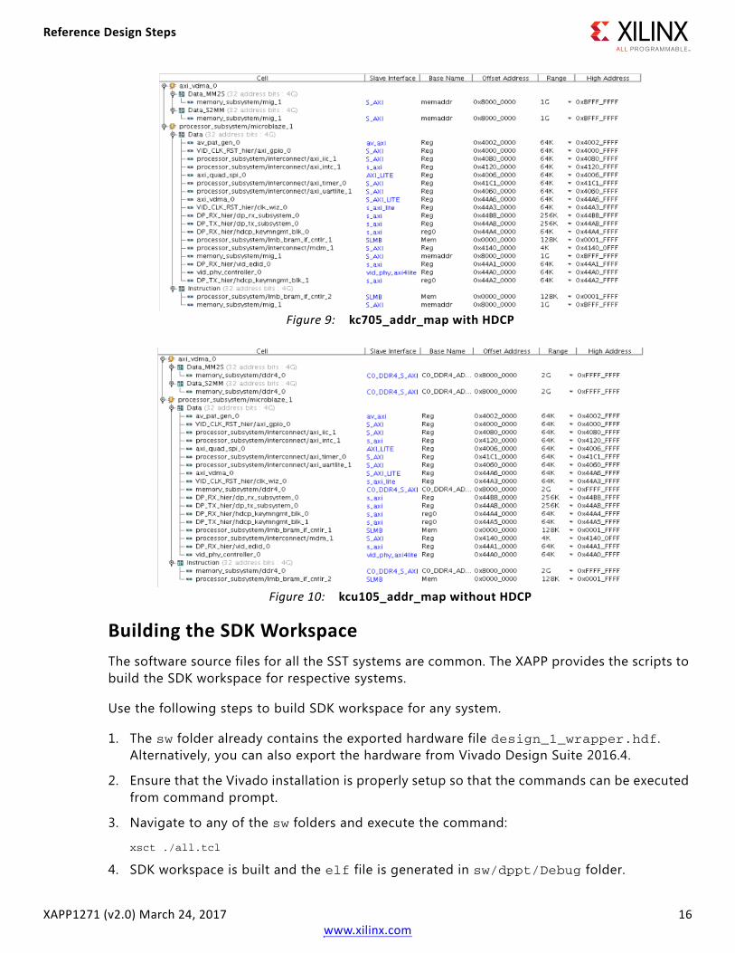
e. Wait until the project is created, output products are generated, design is synthesized and implemented, and the bitstream is generated. Figure 9 and Figure 10 show the address mapping of all the IP cores with the MicroBlaze processor in the system.
Note: Using the respective hw folders, follow the above steps to create the remaining systems.
Reference Design Steps
XAPP1271 (v2.0) March 24, 2017 16www.xilinx.com
Building the SDK WorkspaceThe software source files for all the SST systems are common. The XAPP provides the scripts to build the SDK workspace for respective systems.
Use the following steps to build SDK workspace for any system.
1. The sw folder already contains the exported hardware file design_1_wrapper.hdf. Alternatively, you can also export the hardware from Vivado Design Suite 2016.4.
2. Ensure that the Vivado installation is properly setup so that the commands can be executed from command prompt.
3. Navigate to any of the sw folders and execute the command:
xsct ./all.tcl
4. SDK workspace is built and the elf file is generated in sw/dppt/Debug folder.
X-Ref Target - Figure 9
Figure 9: kc705_addr_map with HDCPX-Ref Target - Figure 10
Figure 10: kcu105_addr_map without HDCP
Reference Design Steps
XAPP1271 (v2.0) March 24, 2017 17www.xilinx.com
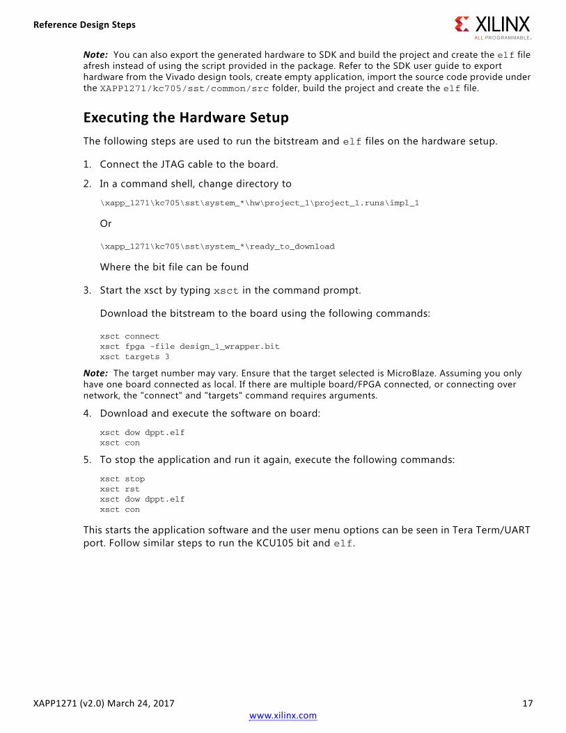
Note: You can also export the generated hardware to SDK and build the project and create the elf file afresh instead of using the script provided in the package. Refer to the SDK user guide to export hardware from the Vivado design tools, create empty application, import the source code provide under the XAPP1271/kc705/sst/common/src folder, build the project and create the elf file.
Executing the Hardware SetupThe following steps are used to run the bitstream and elf files on the hardware setup.
1. Connect the JTAG cable to the board.
2. In a command shell, change directory to
\xapp_1271\kc705\sst\system_*\hw\project_1\project_1.runs\impl_1
Or
\xapp_1271\kc705\sst\system_*\ready_to_download
Where the bit file can be found
3. Start the xsct by typing xsct in the command prompt.
Download the bitstream to the board using the following commands:
xsct connectxsct fpga -file design_1_wrapper.bitxsct targets 3
Note: The target number may vary. Ensure that the target selected is MicroBlaze. Assuming you only have one board connected as local. If there are multiple board/FPGA connected, or connecting over network, the "connect" and "targets" command requires arguments.
4. Download and execute the software on board:
xsct dow dppt.elfxsct con
5. To stop the application and run it again, execute the following commands:
xsct stopxsct rstxsct dow dppt.elfxsct con
This starts the application software and the user menu options can be seen in Tera Term/UART port. Follow similar steps to run the KCU105 bit and elf.

Reference Design Steps
XAPP1271 (v2.0) March 24, 2017 18www.xilinx.com
Display User ConsoleAs soon as the application is executed, it checks if a Monitor is connected or not. If a monitor is already connected, then it starts up the following options as shown in Figure 11 to choose from (KC705).
Selecting either r or s puts the system in Pass-Through mode, where the Video received by RX is forwarded to TX. This configures the vid_phy_controller and sets up the DisplayPort for RX. If a DisplayPort Source (for example, GPU) is already connected to DP RX, then it starts the training. Else, the training happens when the cable is plugged in. As soon as the training is completed, the application starts the DP TX Subsystem. The video should be seen on the monitor once the TX is up. Figure 12 shows the UART transcript. The transcript may differ based on the training done by GPU.
The elf that is shipped with the XAPP shows the following screen as HDCP keys are not set up.
X-Ref Target - Figure 11
Figure 11: DisplayPort User Console with HDCP Enabled Design

Reference Design Steps
XAPP1271 (v2.0) March 24, 2017 19www.xilinx.com
X-Ref Target - Figure 12
Figure 12: DisplayPort Screen without Configuring HDCP KeysX-Ref Target - Figure 13
Figure 13: DisplayPort RX-TX Demo Menu
Reference Design Steps
XAPP1271 (v2.0) March 24, 2017 20www.xilinx.com
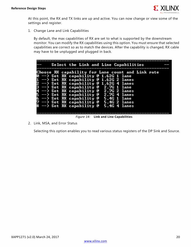
At this point, the RX and TX links are up and active. You can now change or view some of the settings and register.
1. Change Lane and Link Capabilities
By default, the max capabilities of RX are set to what is supported by the downstream monitor. You can modify the RX capabilities using this option. You must ensure that selected capabilities are correct so as to match the devices. After the capability is changed, RX cable may have to be unplugged and plugged in back.
2. Link, MSA, and Error Status
Selecting this option enables you to read various status registers of the DP Sink and Source.
X-Ref Target - Figure 14
Figure 14: Link and Line Capabilities

Reference Design Steps
XAPP1271 (v2.0) March 24, 2017 21www.xilinx.com
3. Toggle HPD to ask for Retraining
This option toggles the HPD for 3 ms which results in retraining.
4. Restart TX Path
This option allows you to restart the complete TX path.
X-Ref Target - Figure 15
Figure 15: RX Debug Data
X-Ref Target - Figure 16
Figure 16: Toggle HPD for Retraining

Reference Design Steps
XAPP1271 (v2.0) March 24, 2017 22www.xilinx.com
5. Switch TX data to internal pattern generator
Selecting this option switches the TX video to internal pattern generator.
6. Switch TX back to RX Video data
Select this option to switch the TX back to RX video.
7. Options w and r
This option lets you to write and read into any of the DP RX register.
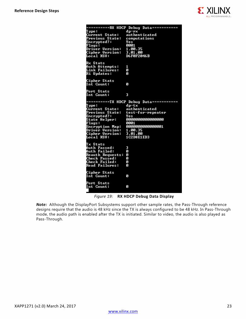
8. Option p
This option lets you to read the HDCP Cipher debug data.
X-Ref Target - Figure 17
Figure 17: Restart TX Path
X-Ref Target - Figure 18
Figure 18: Switch TX Data
Reference Design Steps
XAPP1271 (v2.0) March 24, 2017 23www.xilinx.com
Note: Although the DisplayPort Subsystems support other sample rates, the Pass-Through reference designs require that the audio is 48 kHz since the TX is always configured to be 48 kHz. In Pass-Through mode, the audio path is enabled after the TX is initiated. Similar to video, the audio is also played as Pass-Through.
X-Ref Target - Figure 19
Figure 19: RX HDCP Debug Data Display
Reference Design Steps
XAPP1271 (v2.0) March 24, 2017 24www.xilinx.com
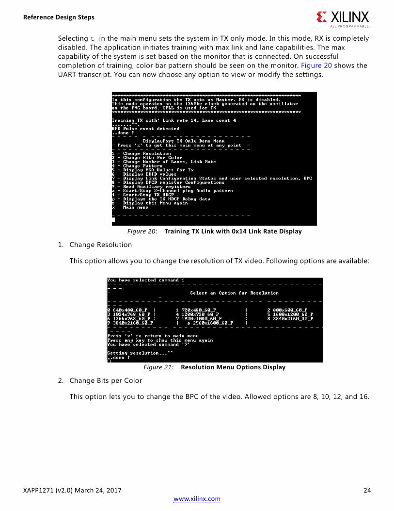
Selecting t in the main menu sets the system in TX only mode. In this mode, RX is completely disabled. The application initiates training with max link and lane capabilities. The max capability of the system is set based on the monitor that is connected. On successful completion of training, color bar pattern should be seen on the monitor. Figure 20 shows the UART transcript. You can now choose any option to view or modify the settings.
1. Change Resolution
This option allows you to change the resolution of TX video. Following options are available:
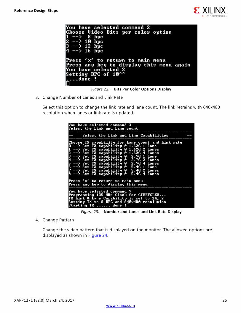
2. Change Bits per Color
This option lets you to change the BPC of the video. Allowed options are 8, 10, 12, and 16.
X-Ref Target - Figure 20
Figure 20: Training TX Link with 0x14 Link Rate Display
X-Ref Target - Figure 21
Figure 21: Resolution Menu Options Display
Reference Design Steps
XAPP1271 (v2.0) March 24, 2017 25www.xilinx.com
3. Change Number of Lanes and Link Rate
Select this option to change the link rate and lane count. The link retrains with 640x480 resolution when lanes or link rate is updated.
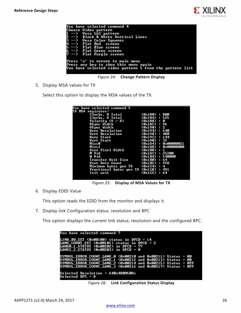
4. Change Pattern
Change the video pattern that is displayed on the monitor. The allowed options are displayed as shown in Figure 24.
X-Ref Target - Figure 22
Figure 22: Bits Per Color Options Display
X-Ref Target - Figure 23
Figure 23: Number and Lanes and Link Rate Display
Reference Design Steps
XAPP1271 (v2.0) March 24, 2017 26www.xilinx.com
5. Display MSA values for TX
Select this option to display the MSA values of the TX.
6. Display EDID Value
This option reads the EDID from the monitor and displays it.
7. Display link Configuration status, resolution and BPC
This option displays the current link status, resolution and the configured BPC.
X-Ref Target - Figure 24
Figure 24: Change Pattern Display
X-Ref Target - Figure 25
Figure 25: Display of MSA Values for TX
X-Ref Target - Figure 26
Figure 26: Link Configuration Status Display
Reference Design Steps
XAPP1271 (v2.0) March 24, 2017 27www.xilinx.com
8. Display DPCD register configuration of the Monitor
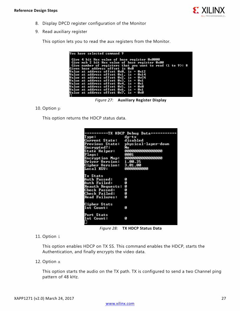
9. Read auxiliary register
This option lets you to read the aux registers from the Monitor.
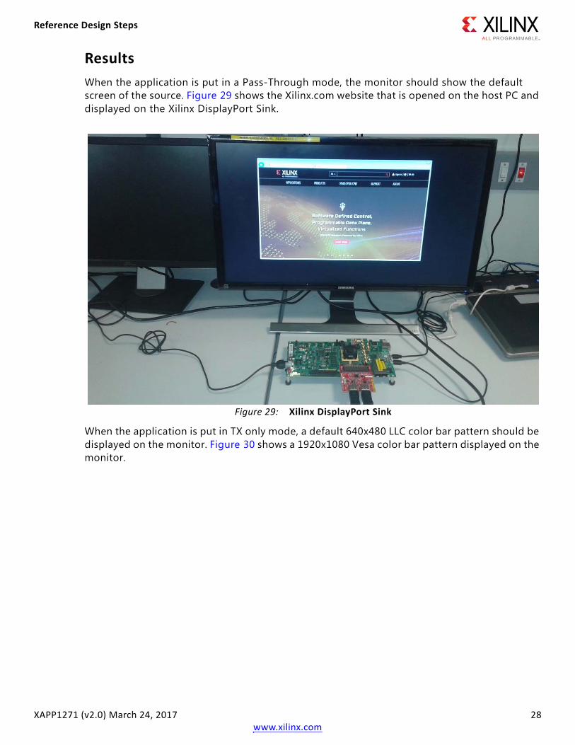
10. Option p
This option returns the HDCP status data.
11. Option i
This option enables HDCP on TX SS. This command enables the HDCP, starts the Authentication, and finally encrypts the video data.
12. Option a
This option starts the audio on the TX path. TX is configured to send a two Channel ping pattern of 48 kHz.
X-Ref Target - Figure 27
Figure 27: Auxiliary Register Display
X-Ref Target - Figure 28
Figure 28: TX HDCP Status Data
Reference Design Steps
XAPP1271 (v2.0) March 24, 2017 28www.xilinx.com
ResultsWhen the application is put in a Pass-Through mode, the monitor should show the default screen of the source. Figure 29 shows the Xilinx.com website that is opened on the host PC and displayed on the Xilinx DisplayPort Sink.
When the application is put in TX only mode, a default 640x480 LLC color bar pattern should be displayed on the monitor. Figure 30 shows a 1920x1080 Vesa color bar pattern displayed on the monitor.
X-Ref Target - Figure 29
Figure 29: Xilinx DisplayPort Sink

Troubleshooting
XAPP1271 (v2.0) March 24, 2017 29www.xilinx.com
TroubleshootingThis section provides the debugging steps for issues in the policy maker software.
Help menu options are provided to read the MSA values, EDID information, Link and Lane status, and DPCD status. The RX Subsystem and its drivers take care of the TI DP159 programming.
Check the following if the design does not work with the provided ready_for_download files:
1. Ensure the quality of the DisplayPort cables.
2. Ensure that the DisplayPort mode is selected in the sink monitor.
3. Ensure that the DP cables are properly connected.
4. Verify the support for the possible resolutions and bits per color options for the monitor that you are testing.
5. Try changing the resolution and BPC from serial port to ensure that there is no link over subscription.
6. When the link is over subscribed or when the monitor goes in sleep mode, even though the TX path is trained, the video may not be visible. Ensure that the link is not over subscribed. Ensure that the monitor’s power cycle is configured to get it out of sleep mode.
7. For more DisplayPort information, see the Xilinx web support page.
X-Ref Target - Figure 30
Figure 30: Display of Color Bar Pattern

Troubleshooting
XAPP1271 (v2.0) March 24, 2017 30www.xilinx.com
Configuring HDCP Keys and Key ManagementThe application software does not use the raw HDCP keys directly. To use the HDCP keys, they have to be first encrypted and then added into the application. You have to manually perform this process. This application note provides the scripts and software that helps you encrypt the HDCP keys.
Using the Encryption Software
To generate the AES encrypted HDCP keys, you must have the following keys:
1. 32-byte AES key
2. Valid HDCP keys
Note: Xilinx does not provide any of the above keys. The application delivered with this XAPP1271 is created with invalid keys and hence does not play HDCP content.
Follow the steps mentioned here to generate the AES encrypted HDCP key block:
1. Unzip the project and go to the hdcp_util/keys directory. You can find the encryption block in this directory.
2. Modify the gDefaultKey array in the following file to a user specified 32 bytes unique key. This is the 32-byte AES key mentioned in point (1) above
XAPP1271/hdcp_util/keys/key-encryptor/common/src/keyfile.c
3. Navigate to XAPP1271/hdcp_util/keys/key-encryptor/build/linux folder and execute the following command from linux terminal.
./build.sh
This creates hdcp-enc.bin file in the same folder.
4. From the same directory, execute the following command to create the AES encrypted file keymgmt_data.c.
./hdcp-enc.bin -c devb1_keys.dat devb2_keys.dat …. devb<n>_keys.dat
Note: The user-provided devb<n>_keys.dat file is expected to have one and only one original HDCP key. An original HDCP key has one 5 byte Key Selection Vector and 40 private keys. If you have multiple HDCP keys, each key should be housed exclusively in one .dat file. Refer dummy.dat file for the expected format.
5. The AES encrypted HDCP key block is now created as an array in the keymgmt_data.c file.
6. Ensure that the following AES keys in the reference design matches with the keys in step 2.
\xapp_1271\kc705\sst\system_2\sw\dppt\src\keymgmt\src\keys.c
The HDCP keys are now encrypted and ready to be used. You can any of the following two ways to use the HDCP keys.

Troubleshooting
XAPP1271 (v2.0) March 24, 2017 31www.xilinx.com
Using the AES Encryption Key Block from the EEPROM
You can use the XAPP/hdcp_util/iic_wr_util/kc705 project provided with the XAPP1271 to write the keys to the EEPROM. You need to copy the AES encrypted block generated in the keymgmt_data.c file as described in the previous section to the "HDCP_KEYS" array in the XAPP/hdcp_util/iic_wr_util/kc705/sw/src/iic_keys.c file.
Note: The size of the keys is calculated and stored in the "HDCP_KEYS_SZ" variable. You should ensure that size of the keys should fit in the EEPROM.
Navigate to the XAPP1271/hdcp_util/iic_wr_util/kc705/sw/ folder. Use the 2016.4 Vivado build in the command prompt and run the following command:
xsct ./all.tcl
This creates the iic_eeprom.elf file in XAPP1271/hdcp_util/iic_wr_util/kc705/sw/iic_eeprom/Debug folder.
You can then use this elf file and the design_1_wrapper.bit file provided in XAPP1271/hdcp_util/iic_wr_util/kc705/ready_to_download folder to program the EEPROM on the board with the AES encrypted keys.
Set gIsKeyWrittenInEeeprom = TRUE in \xapp_1271\kc705\sst\system_2\sw\dppt\src\src\dppt.c file. Ensure that the IIC device ID is correctly set in keygen_config.h file.
Use the same steps to write the keys to EEPROM for KCU105.The IIC utility is also available in the respective folder.
Using the AES Encryption Key Block from the BRAM
To use keys from BRAM, you have to copy the AES Encrypted HDCP keys generated in the previous section to the KEYMGMT_ENCDATA array defined in the following file in the reference design:
\xapp_1271\kc705\sst\system_2\sw\dppt\src\keymgmt\src\keys.c
This process enables the reference design to read keys from BRAM.
Set gIsKeyWrittenInEeeprom = FALSE in \xapp_1271\kc705\sst\system_2\sw\dppt\src\src\dppt.c file.
The steps to use the keys from BRAM for KCU105 are identical to the steps mentioned for KC705 board.

Tested Equipment
XAPP1271 (v2.0) March 24, 2017 32www.xilinx.com
Tested EquipmentTable 5 and Table 6 list the equipment and driver versions that were tested with the XAPP1271.
Table 5: Sink Equipment
Sink Type Brand Name Model Name
Monitor Acer S277HKWMIDPP
Monitor Dell S2817Q
Monitor Dell P2414H
Monitor Dell MST P2415Q
Monitor LG 27UD68P
Monitor ASUS PB279
Monitor Philips 288P6LJ
Monitor Dell MST U2413
Table 6: Source Equipment
Sink Type Brand Name Model Name Driver Version Platform
GPU NVIDIA GTX 980 21.21.13.7619 Windows 7
GPU AMD RX 460 21.19.384.37 Windows 10
GPU AMD FirePro V7900 15.201.2401 Windows 10
Laptop Apple MBP – macOS
GPU AMD Radeon R7 350 21.19.384.37 Windows 10
PC AMD Radeon HD 6450 – CentOS
GPU NVIDIA GTX 1080 21.21.13.7290 Windows 10
GPU NVIDIA Quadro M4000 21.21.13.7849 Windows 10
Tester Unigraf DPT-200 – –

References
XAPP1271 (v2.0) March 24, 2017 33www.xilinx.com
ReferencesThis section lists the references used in this document.
1. DisplayPort RX Subsystem Product Guide (PG233)
2. DisplayPort TX Subsystem Product Guide (PG199)
3. Video PHY Controller v2.0 Product Guide (PG230)
4. LogiCORE IP DisplayPort v7.0 Product Guide (PG064)
5. Vivado Design Suite User Guide: Designing IP Subsystems using IP Integrator (UG994)
6. KCU105 Board User Guide (UG917)
7. KC705 Evaluation Board for the Kintex-7 FPGA (UG810)
8. Xilinx Kintex-7 FPGA KC705 Evaluation Kit (https://www.xilinx.com/products/boards-and-kits/EK-K7-KC705-G.html)
9. Xilinx Kintex UltraScale FPGA KCU105 Evaluation Kit (https://www.xilinx.com/products/boards-and-kits/kcu105.html)
Revision History
XAPP1271 (v2.0) March 24, 2017 34www.xilinx.com
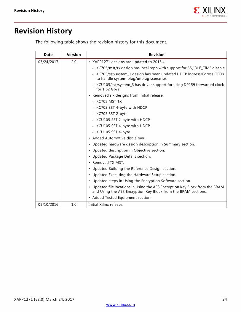
Revision HistoryThe following table shows the revision history for this document.
Date Version Revision
03/24/2017 2.0 • XAPP1271 designs are updated to 2016.4
° KC705/mst/rx design has local repo with support for BS_IDLE_TIME disable
° KC705/sst/system_1 design has been updated HDCP Ingress/Egress FIFOs to handle system plug/unplug scenarios
° KCU105/sst/system_3 has driver support for using DP159 forwarded clock for 1.62 Gb/s
• Removed six designs from initial release:
° KC705 MST TX
° KC705 SST 4-byte with HDCP
° KC705 SST 2-byte
° KCU105 SST 2-byte with HDCP
° KCU105 SST 4-byte with HDCP
° KCU105 SST 4-byte
• Added Automotive disclaimer.
• Updated hardware design description in Summary section.
• Updated description in Objective section.
• Updated Package Details section.
• Removed TX MST.
• Updated Building the Reference Design section.
• Updated Executing the Hardware Setup section.
• Updated steps in Using the Encryption Software section.
• Updated file locations in Using the AES Encryption Key Block from the BRAM and Using the AES Encryption Key Block from the BRAM sections.
• Added Tested Equipment section.
05/10/2016 1.0 Initial Xilinx release.
Please Read: Important Legal Notices
XAPP1271 (v2.0) March 24, 2017 35www.xilinx.com
Please Read: Important Legal NoticesThe information disclosed to you hereunder (the “Materials”) is provided solely for the selection and use of Xilinx products. To the maximum extent permitted by applicable law: (1) Materials are made available "AS IS" and with all faults, Xilinx hereby DISCLAIMS ALL WARRANTIES AND CONDITIONS, EXPRESS, IMPLIED, OR STATUTORY, INCLUDING BUT NOT LIMITED TO WARRANTIES OF MERCHANTABILITY, NON-INFRINGEMENT, OR FITNESS FOR ANY PARTICULAR PURPOSE; and (2) Xilinx shall not be liable (whether in contract or tort, including negligence, or under any other theory of liability) for any loss or damage of any kind or nature related to, arising under, or in connection with, the Materials (including your use of the Materials), including for any direct, indirect, special, incidental, or consequential loss or damage (including loss of data, profits, goodwill, or any type of loss or damage suffered as a result of any action brought by a third party) even if such damage or loss was reasonably foreseeable or Xilinx had been advised of the possibility of the same. Xilinx assumes no obligation to correct any errors contained in the Materials or to notify you of updates to the Materials or to product specifications. You may not reproduce, modify, distribute, or publicly display the Materials without prior written consent. Certain products are subject to the terms and conditions of Xilinx’s limited warranty, please refer to Xilinx’s Terms of Sale which can be viewed at https://www.xilinx.com/legal.htm#tos; IP cores may be subject to warranty and support terms contained in a license issued to you by Xilinx. Xilinx products are not designed or intended to be fail-safe or for use in any application requiring fail-safe performance; you assume sole risk and liability for use of Xilinx products in such critical applications, please refer to Xilinx’s Terms of Sale which can be viewed at https://www.xilinx.com/legal.htm#tos.AUTOMOTIVE APPLICATIONS DISCLAIMERAUTOMOTIVE PRODUCTS (IDENTIFIED AS "XA" IN THE PART NUMBER) ARE NOT WARRANTED FOR USE IN THE DEPLOYMENT OF AIRBAGS OR FOR USE IN APPLICATIONS THAT AFFECT CONTROL OF A VEHICLE ("SAFETY APPLICATION") UNLESS THERE IS A SAFETY CONCEPT OR REDUNDANCY FEATURE CONSISTENT WITH THE ISO 26262 AUTOMOTIVE SAFETY STANDARD ("SAFETY DESIGN"). CUSTOMER SHALL, PRIOR TO USING OR DISTRIBUTING ANY SYSTEMS THAT INCORPORATE PRODUCTS, THOROUGHLY TEST SUCH SYSTEMS FOR SAFETY PURPOSES. USE OF PRODUCTS IN A SAFETY APPLICATION WITHOUT A SAFETY DESIGN IS FULLY AT THE RISK OF CUSTOMER, SUBJECT ONLY TO APPLICABLE LAWS AND REGULATIONS GOVERNING LIMITATIONS ON PRODUCT LIABILITY.© Copyright 2011–2017 Xilinx, Inc. Xilinx, the Xilinx logo, Artix, ISE, Kintex, Spartan, Virtex, Vivado, Zynq, and other designated brands included herein are trademarks of Xilinx in the United States and other countries. All other trademarks are the property of their respective owners.