Embed Size (px)
Citation preview
Dislocation decorrelation and relationship to deformation microtwinsduring creep of a c0 precipitate strengthened Ni-based superalloy
R.R. Unocic a,b,⇑, N. Zhou b, L. Kovarik b,c, C. Shen d, Y. Wang b, M.J. Mills b
a Materials Science and Technology Division, Oak Ridge National Laboratory, Oak Ridge, TN 37831, USAb Department of Materials Science and Engineering, The Ohio State University, Columbus, OH 43210, USA
c EMSL, Pacific Northwest National Laboratory, Richland, WA 99352, USAd GE Global Research, Niskayuna, NY 12309, USA
Received 9 May 2011; received in revised form 29 July 2011
Abstract
The evolution of microtwins during high temperature creep deformation in a c0 strengthened Ni-based superalloy has been investi-gated through a combination of creep testing, transmission electron microscopy (TEM), theoretical modeling, and computer simulation.Experimentally, microtwin nucleation sources were identified and their evolution was tracked by characterizing the deformation sub-structure at different stages of creep deformation. Deformation is highly localized around stress concentrators such as carbides, boridesand serrated grain boundaries, which act as sources of a/2h110i matrix-type dislocations. Due to fine channels between the c0 particles,coupled with a low c matrix stacking fault energy, the a/2h11 0i matrix dislocations dissociate into a/6h112i Shockley partials, whichwere commonly observed to be decorrelated from one another, creating extended intrinsic stacking faults in the c matrix. Microtwinsare common and form via Shockley partial dislocations, cooperatively shearing both the c and c0 phases on adjacent {11 1} glide planes.The TEM observations lead directly to an analysis of dislocation–precipitate interactions. The important processes of dislocation disso-ciation and decorrelation were modeled in detail through phase field simulations and theoretical analyses based on Orowan looping, pro-viding a comprehensive insight into the microstructural features and applied stress conditions that favor the microtwinning deformationmode in c0 strengthened Ni-based superalloys.Published by Elsevier Ltd. on behalf of Acta Materialia Inc.
Keywords: Creep; Microtwinning; Shockley partial dislocations; Diffusion; Atomic ordering
1. Introduction
Ni-based superalloys are a class of alloys that are pre-dominantly used in the aerospace industry in hot sectionsof gas turbine engine components. These alloys possessan attractive combination of attributes, such as high tem-perature mechanical properties (strength, creep, and fati-gue) and resistance to high temperature oxidation. Thehigh temperature mechanical properties are largely dictatedby the presence of ordered, L12 structured, Ni3Al-based c0
precipitates, which are coherently embedded in a solid solu-tion c matrix (fcc structure). Since these materials are uti-lized at elevated temperatures, time-dependent creepdeformation is of principal concern. There have beennumerous detailed transmission electron microscopy(TEM) studies focused on elucidating the creep deforma-tion mechanisms and determining the associated implica-tions for creep rate controlling dislocation processes[1–8]. Mechanisms previously identified include dislocationclimb, looping, and stacking fault related c0 shearing. Aparticular mechanism that has been reported more recentlyfollowing high temperature creep deformation is microt-winning [9–17], which is surprising since twinning in fcccrystals is generally considered a low temperature, high
1359-6454/$36.00 Published by Elsevier Ltd. on behalf of Acta Materialia Inc.
doi:10.1016/j.actamat.2011.07.069
⇑ Corresponding author at: Materials Science and Technology Division,Oak Ridge National Laboratory, Oak Ridge, TN 37831, USA. Tel.: +1865 574 0096.
E-mail address: [email protected] (R.R. Unocic).
www.elsevier.com/locate/actamat
Available online at www.sciencedirect.com
Acta Materialia 59 (2011) 7325–7339

Report Documentation Page Form ApprovedOMB No. 0704-0188
Public reporting burden for the collection of information is estimated to average 1 hour per response, including the time for reviewing instructions, searching existing data sources, gathering andmaintaining the data needed, and completing and reviewing the collection of information. Send comments regarding this burden estimate or any other aspect of this collection of information,including suggestions for reducing this burden, to Washington Headquarters Services, Directorate for Information Operations and Reports, 1215 Jefferson Davis Highway, Suite 1204, ArlingtonVA 22202-4302. Respondents should be aware that notwithstanding any other provision of law, no person shall be subject to a penalty for failing to comply with a collection of information if itdoes not display a currently valid OMB control number.
1. REPORT DATE JUL 2011 2. REPORT TYPE
3. DATES COVERED 00-00-2011 to 00-00-2011
4. TITLE AND SUBTITLE Dislocation decorrelation and relationship to deformation microtwinsduring creep of a Y’ precipitate strengthened Ni-based superalloy
5a. CONTRACT NUMBER
5b. GRANT NUMBER
5c. PROGRAM ELEMENT NUMBER
6. AUTHOR(S) 5d. PROJECT NUMBER
5e. TASK NUMBER
5f. WORK UNIT NUMBER
7. PERFORMING ORGANIZATION NAME(S) AND ADDRESS(ES) Oak Ridge National Laboratory,Materials Science and TechnologyDivision,Oak Ridge,TN,37831
8. PERFORMING ORGANIZATIONREPORT NUMBER
9. SPONSORING/MONITORING AGENCY NAME(S) AND ADDRESS(ES) 10. SPONSOR/MONITOR’S ACRONYM(S)
11. SPONSOR/MONITOR’S REPORT NUMBER(S)
12. DISTRIBUTION/AVAILABILITY STATEMENT Approved for public release; distribution unlimited
13. SUPPLEMENTARY NOTES
14. ABSTRACT The evolution of microtwins during high temperature creep deformation in a c0 strengthened Ni-basedsuperalloy has been investigated through a combination of creep testing, transmission electron microscopy(TEM), theoretical modeling, and computer simulation. Experimentally, microtwin nucleation sourceswere identified and their evolution was tracked by characterizing the deformation substructure at differentstages of creep deformation. Deformation is highly localized around stress concentrators such as carbides,borides and serrated grain boundaries, which act as sources of a/2h110i matrix-type dislocations. Due tofine channels between the c0 particles coupled with a low c matrix stacking fault energy, the a/2h110imatrix dislocations dissociate into a/6h112i Shockley partials, which were commonly observed to bedecorrelated from one another, creating extended intrinsic stacking faults in the c matrix. Microtwins arecommon and form via Shockley partial dislocations, cooperatively shearing both the c and c0 phases onadjacent {11 1} glide planes. The TEM observations lead directly to an analysis of dislocation?precipitateinteractions. The important processes of dislocation dissociation and decorrelation were modeled in detailthrough phase field simulations and theoretical analyses based on Orowan looping, providing acomprehensive insight into the microstructural features and applied stress conditions that favor themicrotwinning deformation mode in c0 strengthened Ni-based superalloys.
15. SUBJECT TERMS
16. SECURITY CLASSIFICATION OF: 17. LIMITATION OF ABSTRACT Same as
Report (SAR)
18. NUMBEROF PAGES
15
19a. NAME OFRESPONSIBLE PERSON
a. REPORT unclassified
b. ABSTRACT unclassified
c. THIS PAGE unclassified

Standard Form 298 (Rev. 8-98) Prescribed by ANSI Std Z39-18
strain rate deformation mode, in contrast to the high tem-perature, low strain rate creep conditions that have beenobserved in these alloys [18].
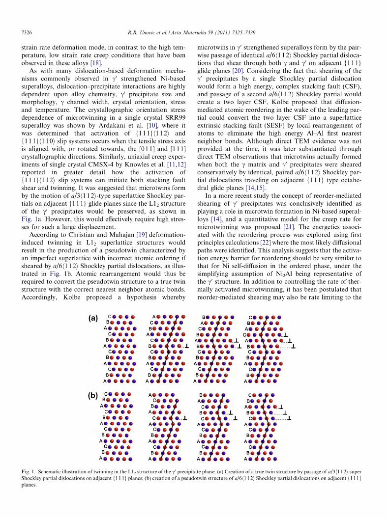
As with many dislocation-based deformation mecha-nisms commonly observed in c0 strengthened Ni-basedsuperalloys, dislocation–precipitate interactions are highlydependent upon alloy chemistry, c0 precipitate size andmorphology, c channel width, crystal orientation, stressand temperature. The crystallographic orientation stressdependence of microtwinning in a single crystal SRR99superalloy was shown by Ardakani et al. [10], where itwas determined that activation of {111}h112i and{11 1}h110i slip systems occurs when the tensile stress axisis aligned with, or rotated towards, the [011] and [111]crystallographic directions. Similarly, uniaxial creep exper-iments of single crystal CMSX-4 by Knowles et al. [11,12]reported in greater detail how the activation of{11 1}h112i slip systems can initiate both stacking faultshear and twinning. It was suggested that microtwins formby the motion of a/3h112i-type superlattice Shockley par-tials on adjacent {111} glide planes since the L12 structureof the c0 precipitates would be preserved, as shown inFig. 1a. However, this would effectively require high stres-ses for such a large displacement.
According to Christian and Mahajan [19] deformation-induced twinning in L12 superlattice structures wouldresult in the production of a pseudotwin characterized byan imperfect superlattice with incorrect atomic ordering ifsheared by a/6h1 12i Shockley partial dislocations, as illus-trated in Fig. 1b. Atomic rearrangement would thus berequired to convert the pseudotwin structure to a true twinstructure with the correct nearest neighbor atomic bonds.Accordingly, Kolbe proposed a hypothesis whereby
microtwins in c0 strengthened superalloys form by the pair-wise passage of identical a/6h112i Shockley partial disloca-tions that shear through both c and c0 on adjacent {11 1}glide planes [20]. Considering the fact that shearing of thec0 precipitates by a single Shockley partial dislocationwould form a high energy, complex stacking fault (CSF),and passage of a second a/6h112i Shockley partial wouldcreate a two layer CSF, Kolbe proposed that diffusion-mediated atomic reordering in the wake of the leading par-tial could convert the two layer CSF into a superlatticeextrinsic stacking fault (SESF) by local rearrangement ofatoms to eliminate the high energy Al–Al first nearestneighbor bonds. Although direct TEM evidence was notprovided at the time, it was later substantiated throughdirect TEM observations that microtwins actually formedwhen both the c matrix and c0 precipitates were shearedconservatively by identical, paired a/6h1 12i Shockley par-tial dislocations traveling on adjacent {111} type octahe-dral glide planes [14,15].
In a more recent study the concept of reorder-mediatedshearing of c0 precipitates was conclusively identified asplaying a role in microtwin formation in Ni-based superal-loys [14], and a quantitative model for the creep rate formicrotwinning was proposed [21]. The energetics associ-ated with the reordering process was explored using firstprinciples calculations [22] where the most likely diffusionalpaths were identified. This analysis suggests that the activa-tion energy barrier for reordering should be very similar tothat for Ni self-diffusion in the ordered phase, under thesimplifying assumption of Ni3Al being representative ofthe c0 structure. In addition to controlling the rate of ther-mally activated microtwinning, it has been postulated thatreorder-mediated shearing may also be rate limiting to the
Fig. 1. Schematic illustration of twinning in the L12 structure of the c0 precipitate phase. (a) Creation of a true twin structure by passage of a/3h112i superShockley partial dislocations on adjacent {111} planes; (b) creation of a pseudotwin structure of a/6h112i Shockley partial dislocations on adjacent {111}planes.
7326 R.R. Unocic et al. / Acta Materialia 59 (2011) 7325–7339
formation of both superlattice intrinsic and extrinsic stack-ing faults in superalloys at elevated temperatures [22].Based on the concept of the generalized stacking faultenergy landscape, phase field modeling has been used toparametrically study microstructural effects on the criti-cally resolved shear stress, which was also coupled withtemperature effects on the atomic reordering kineticsrelated to dislocation glide [23]. The aforementioned ratelimiting process helps explain the dynamic motion of twin-ning partial dislocations and microtwin propagation cap-tured by Legros et al. [17] during elevated temperaturein situ TEM straining experiments of a rafted c/c0 superal-loy, where it was observed that the twinning partial dislo-cations moved at a higher velocity in the c phase and alower velocity in the c0 phase.
Recent research on creep deformation mechanisms inpolycrystalline Ni-based turbine disk superalloy Rene 104has shown that microtwinning is a dominant deformationmechanism during creep at a test temperature of 677 �Cand a stress level of 690 MPa [16]. Deformation in this casewas carried out to such a high level of plastic deformation(2.0% strain) that it was difficult to capture discrete loca-tions where microtwins may have initiated or terminated.Due to the present lack of experimental evidence on micro-twin initiation and evolution there has yet to be a detaileddescription of how the microstructure and other externalvariables (stress and temperature) dictate the microtwin-ning process from initiation to propagation. Therefore,the motivation for this study was to perform an in-depthexperimental, theoretical, and computational study on theevolution of the microtwinning deformation mode byfocusing on the salient microstructural features that pro-mote microtwinning over other deformation mechanisms.
2. Materials and experimental procedure
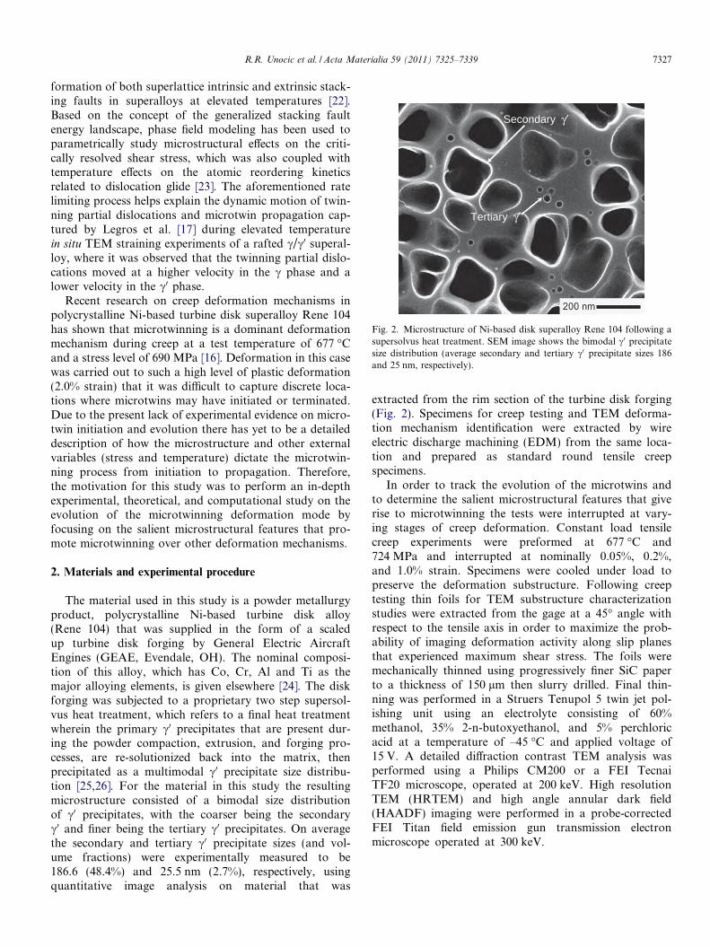
The material used in this study is a powder metallurgyproduct, polycrystalline Ni-based turbine disk alloy(Rene 104) that was supplied in the form of a scaledup turbine disk forging by General Electric AircraftEngines (GEAE, Evendale, OH). The nominal composi-tion of this alloy, which has Co, Cr, Al and Ti as themajor alloying elements, is given elsewhere [24]. The diskforging was subjected to a proprietary two step supersol-vus heat treatment, which refers to a final heat treatmentwherein the primary c0 precipitates that are present dur-ing the powder compaction, extrusion, and forging pro-cesses, are re-solutionized back into the matrix, thenprecipitated as a multimodal c0 precipitate size distribu-tion [25,26]. For the material in this study the resultingmicrostructure consisted of a bimodal size distributionof c0 precipitates, with the coarser being the secondaryc0 and finer being the tertiary c0 precipitates. On averagethe secondary and tertiary c0 precipitate sizes (and vol-ume fractions) were experimentally measured to be186.6 (48.4%) and 25.5 nm (2.7%), respectively, usingquantitative image analysis on material that was
extracted from the rim section of the turbine disk forging(Fig. 2). Specimens for creep testing and TEM deforma-tion mechanism identification were extracted by wireelectric discharge machining (EDM) from the same loca-tion and prepared as standard round tensile creepspecimens.
In order to track the evolution of the microtwins andto determine the salient microstructural features that giverise to microtwinning the tests were interrupted at vary-ing stages of creep deformation. Constant load tensilecreep experiments were preformed at 677 �C and724 MPa and interrupted at nominally 0.05%, 0.2%,and 1.0% strain. Specimens were cooled under load topreserve the deformation substructure. Following creeptesting thin foils for TEM substructure characterizationstudies were extracted from the gage at a 45� angle withrespect to the tensile axis in order to maximize the prob-ability of imaging deformation activity along slip planesthat experienced maximum shear stress. The foils weremechanically thinned using progressively finer SiC paperto a thickness of 150 lm then slurry drilled. Final thin-ning was performed in a Struers Tenupol 5 twin jet pol-ishing unit using an electrolyte consisting of 60%methanol, 35% 2-n-butoxyethanol, and 5% perchloricacid at a temperature of –45 �C and applied voltage of15 V. A detailed diffraction contrast TEM analysis wasperformed using a Philips CM200 or a FEI TecnaiTF20 microscope, operated at 200 keV. High resolutionTEM (HRTEM) and high angle annular dark field(HAADF) imaging were performed in a probe-correctedFEI Titan field emission gun transmission electronmicroscope operated at 300 keV.
Secondary γ′
Tertiary γ′
Fig. 2. Microstructure of Ni-based disk superalloy Rene 104 following asupersolvus heat treatment. SEM image shows the bimodal c0 precipitatesize distribution (average secondary and tertiary c0 precipitate sizes 186and 25 nm, respectively).
R.R. Unocic et al. / Acta Materialia 59 (2011) 7325–7339 7327
3. Results
3.1. Microtwinning as the dominant deformation process at
larger strain
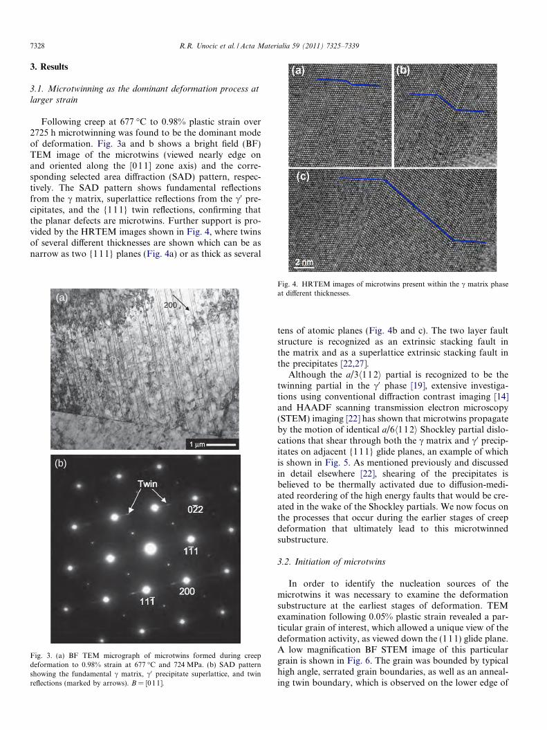
Following creep at 677 �C to 0.98% plastic strain over2725 h microtwinning was found to be the dominant modeof deformation. Fig. 3a and b shows a bright field (BF)TEM image of the microtwins (viewed nearly edge onand oriented along the [011] zone axis) and the corre-sponding selected area diffraction (SAD) pattern, respec-tively. The SAD pattern shows fundamental reflectionsfrom the c matrix, superlattice reflections from the c0 pre-cipitates, and the {111} twin reflections, confirming thatthe planar defects are microtwins. Further support is pro-vided by the HRTEM images shown in Fig. 4, where twinsof several different thicknesses are shown which can be asnarrow as two {111} planes (Fig. 4a) or as thick as several
tens of atomic planes (Fig. 4b and c). The two layer faultstructure is recognized as an extrinsic stacking fault inthe matrix and as a superlattice extrinsic stacking fault inthe precipitates [22,27].
Although the a/3h112i partial is recognized to be thetwinning partial in the c0 phase [19], extensive investiga-tions using conventional diffraction contrast imaging [14]and HAADF scanning transmission electron microscopy(STEM) imaging [22] has shown that microtwins propagateby the motion of identical a/6h1 12i Shockley partial dislo-cations that shear through both the c matrix and c0 precip-itates on adjacent {111} glide planes, an example of whichis shown in Fig. 5. As mentioned previously and discussedin detail elsewhere [22], shearing of the precipitates isbelieved to be thermally activated due to diffusion-medi-ated reordering of the high energy faults that would be cre-ated in the wake of the Shockley partials. We now focus onthe processes that occur during the earlier stages of creepdeformation that ultimately lead to this microtwinnedsubstructure.
3.2. Initiation of microtwins
In order to identify the nucleation sources of themicrotwins it was necessary to examine the deformationsubstructure at the earliest stages of deformation. TEMexamination following 0.05% plastic strain revealed a par-ticular grain of interest, which allowed a unique view of thedeformation activity, as viewed down the (111) glide plane.A low magnification BF STEM image of this particulargrain is shown in Fig. 6. The grain was bounded by typicalhigh angle, serrated grain boundaries, as well as an anneal-ing twin boundary, which is observed on the lower edge of
200(a)
(b)
Fig. 3. (a) BF TEM micrograph of microtwins formed during creepdeformation to 0.98% strain at 677 �C and 724 MPa. (b) SAD patternshowing the fundamental c matrix, c0 precipitate superlattice, and twinreflections (marked by arrows). B = [011].
Fig. 4. HRTEM images of microtwins present within the c matrix phaseat different thicknesses.
7328 R.R. Unocic et al. / Acta Materialia 59 (2011) 7325–7339

the image. A number of carbide and/or boride phases arepresent, both along grain boundaries and within the graininteriors. These second phase particles are typically foundin this and other polycrystalline superalloys produced bypowder metallurgical processes [28]. For instance, thechemical composition of the intragranular particles asdetermined by energy dispersive X-ray spectroscopy tendedto be enriched in Ti, Ta, Co, Cr, Mo, and Nb, indicating aMC type carbide [29]. Both M23C6 carbides, enriched inCo, Cr, Mo, C and B, as well as borides, have also beenobserved along grain boundaries. Upon closer examinationthese minor carbide and boride phases appear to be distinctorigins of deformation activity. The nascent deformationactivities near these second phases are in the form of both
dislocations and stacking faults in the matrix. Note that thestacking faults viewed in this orientation, with the faultplane nearly parallel to the foil plane, do not show thealternating bright and dark fringes normally expected whencharacterizing stacking faults. Instead, the stacking faultsappear as dark grey regions and are present within the cmatrix.
3.3. Detailed TEM deformation substructure analysis
Additional diffraction contrast TEM analysis wasrequired to confirm that dislocations emitted from thegrain boundary carbides/borides or intragranular carbidesources readily dissociate into Shockley partial disloca-tions. Fig. 7 presents a series of higher magnification BFTEM images (using different two beam diffraction condi-tions) of the defect structures near one of the intragranularcarbides shown in Fig. 6. The specific dislocation configu-ration highlighted in the schematic illustration of Fig. 7findicates that the leading partial dislocation has “perco-lated” between the secondary c0 precipitates, leaving themunsheared, while some of the finer scale tertiary c0 precipi-tates have been looped by the leading partial. The stackingfault and associated Shockley partial dislocations weredetermined to be on the (111) glide plane (which is closeto the foil normal in this grain) based on the g � R invisibil-ity criterion for planar faults in the fcc crystal structure,where R is the fault vector. The stacking fault is visible inFig. 7a since g ¼ �111 and g � R is not zero. For this casethe leading partial dislocation is visible but the trailingone is not. Conversely, using g ¼ 1�11 (Fig. 7b) the trailingdislocation is visible while the leading one is not. Addi-tional g vectors were chosen such that g � R = 0 and thecontrast due to the partial dislocations was not obscuredby the stacking fault. For instance, the trailing partial dis-location is visible for g ¼ �220 (Fig. 7c) and g ¼ 02�2(Fig. 7d), while it is invisible when imaged with g ¼ 20�2(Fig. 7e). The leading partial dislocation is visible whenimaged with g ¼ �220 and g ¼ 20�2, while it is invisible withg ¼ 02�2. Based on this analysis, the leading partial disloca-tion has a Burgers vector of a=6½�2 1 1� and the trailing par-tial dislocation has a Burgers vector of a=6½�1 2 �1�, producedby the dissociation of a perfect a=2½�1 1 0� matrix disloca-tion. For a clearer illustration of this dislocation configura-tion a schematic is presented in Fig. 7f with regard to the(111) plane of the Thompson’s tetrahedron. In additionto determining the Burgers vectors of the dislocations, itis also evident that a single slip system was operative in thisregion, since all the dislocations can be accounted for bycontrast from these perfect and Shockley partialdislocations.
With increasing creep deformation to 0.2% strain thesame stacking faults are observed; however, they are pres-ent at a much higher density. The local plastic zone near anintragranular carbide is shown at a higher TEM magnifica-tion in Fig. 8, which shows several a/2h110i dislocationsoriginating from an intragranular carbide source. In this
Fig. 5. Representative HAADF STEM image of microtwin shearingthrough both the c matrix and c0 precipitate.
Intragranular Carbides
Serrated Grain Boundary
Twin Boundary
Fig. 6. BF STEM image of the deformation substructure following creepto 0.05% strain at 677 �C and 724 MPa showing deformation activitybeing emitted from second phase particles and grain boundaries.
R.R. Unocic et al. / Acta Materialia 59 (2011) 7325–7339 7329

case dislocation emissions on inclined {111} glide planesare observed. The dislocations directly adjacent to the car-bide are comprised predominantly of narrowly dissociateda/2h110i dislocations, all contained within the c matrix.There are also a few instances where significantly wider dis-sociation events occurred, creating wide stacking faults(labeled F in Fig. 8a). Fig. 8b shows the defect structurea few hundred nanometers from the same carbide, exhibit-ing primarily stacking faults in the matrix, with Shockleypartials looping the secondary c0 precipitates. Thus, these
observations suggest that while a/2h1 10i dislocations areinitially generated near carbides, a progression towards afully dissociated (decorrelated) condition occurs, wherethe Shockley partials comprising the a/2h110i dislocationsare widely separated.
It is important to note that these stacking fault struc-tures appear to be present at a similar density to thatobserved for microtwins formed at larger strain, which fur-ther confirms the importance of the former as a precursorto microtwinning. In addition, nearly all of the grains
Fig. 7. A series of BF TEM images showing the diffraction contrast analysis of perfect and partial dislocations bounding a stacking fault in the c matrixusing the following imaging conditions: (a) g ¼ �111, B = [211]; (b) g ¼ 1�11, B = [110]; (c) g ¼ �220, B = [111]; (d) g ¼ 02�2, B = [111]; (e) g ¼ 20�2,B = [111]. (f) Schematic illustration of the dislocation configurations along with Thompson tetrahedron notation of the Burgers vector.
7330 R.R. Unocic et al. / Acta Materialia 59 (2011) 7325–7339
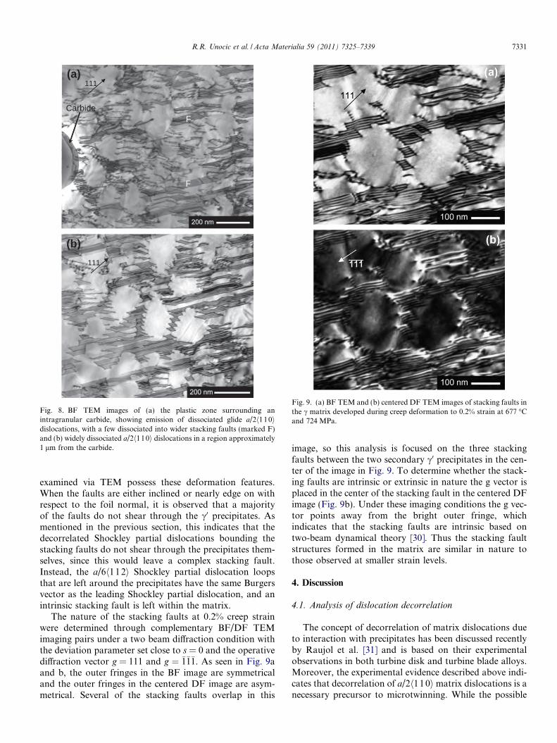
examined via TEM possess these deformation features.When the faults are either inclined or nearly edge on withrespect to the foil normal, it is observed that a majorityof the faults do not shear through the c0 precipitates. Asmentioned in the previous section, this indicates that thedecorrelated Shockley partial dislocations bounding thestacking faults do not shear through the precipitates them-selves, since this would leave a complex stacking fault.Instead, the a/6h112i Shockley partial dislocation loopsthat are left around the precipitates have the same Burgersvector as the leading Shockley partial dislocation, and anintrinsic stacking fault is left within the matrix.
The nature of the stacking faults at 0.2% creep strainwere determined through complementary BF/DF TEMimaging pairs under a two beam diffraction condition withthe deviation parameter set close to s = 0 and the operativediffraction vector g = 111 and g ¼ �1�1�1. As seen in Fig. 9aand b, the outer fringes in the BF image are symmetricaland the outer fringes in the centered DF image are asym-metrical. Several of the stacking faults overlap in this
image, so this analysis is focused on the three stackingfaults between the two secondary c0 precipitates in the cen-ter of the image in Fig. 9. To determine whether the stack-ing faults are intrinsic or extrinsic in nature the g vector isplaced in the center of the stacking fault in the centered DFimage (Fig. 9b). Under these imaging conditions the g vec-tor points away from the bright outer fringe, whichindicates that the stacking faults are intrinsic based ontwo-beam dynamical theory [30]. Thus the stacking faultstructures formed in the matrix are similar in nature tothose observed at smaller strain levels.
4. Discussion
4.1. Analysis of dislocation decorrelation
The concept of decorrelation of matrix dislocations dueto interaction with precipitates has been discussed recentlyby Raujol et al. [31] and is based on their experimentalobservations in both turbine disk and turbine blade alloys.Moreover, the experimental evidence described above indi-cates that decorrelation of a/2h11 0imatrix dislocations is anecessary precursor to microtwinning. While the possible
Carbide
F
F
111(a)
(b)111
Fig. 8. BF TEM images of (a) the plastic zone surrounding anintragranular carbide, showing emission of dissociated glide a/2h110idislocations, with a few dissociated into wider stacking faults (marked F)and (b) widely dissociated a/2h110i dislocations in a region approximately1 lm from the carbide.
Fig. 9. (a) BF TEM and (b) centered DF TEM images of stacking faults inthe c matrix developed during creep deformation to 0.2% strain at 677 �Cand 724 MPa.
R.R. Unocic et al. / Acta Materialia 59 (2011) 7325–7339 7331
mechanisms for twin thickening will be discussed below, inthis section we focus on developing a fundamental under-standing of, and a predictive model for, the conditionsfor dislocation decorrelation.
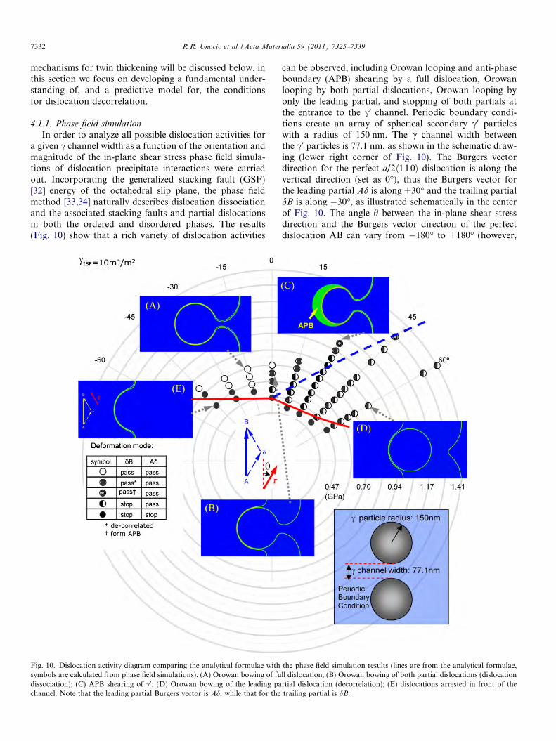
4.1.1. Phase field simulationIn order to analyze all possible dislocation activities for
a given c channel width as a function of the orientation andmagnitude of the in-plane shear stress phase field simula-tions of dislocation–precipitate interactions were carriedout. Incorporating the generalized stacking fault (GSF)[32] energy of the octahedral slip plane, the phase fieldmethod [33,34] naturally describes dislocation dissociationand the associated stacking faults and partial dislocationsin both the ordered and disordered phases. The results(Fig. 10) show that a rich variety of dislocation activities
can be observed, including Orowan looping and anti-phaseboundary (APB) shearing by a full dislocation, Orowanlooping by both partial dislocations, Orowan looping byonly the leading partial, and stopping of both partials atthe entrance to the c0 channel. Periodic boundary condi-tions create an array of spherical secondary c0 particleswith a radius of 150 nm. The c channel width betweenthe c0 particles is 77.1 nm, as shown in the schematic draw-ing (lower right corner of Fig. 10). The Burgers vectordirection for the perfect a/2h110i dislocation is along thevertical direction (set as 0�), thus the Burgers vector forthe leading partial Ad is along +30� and the trailing partialdB is along �30�, as illustrated schematically in the centerof Fig. 10. The angle h between the in-plane shear stressdirection and the Burgers vector direction of the perfectdislocation AB can vary from �180� to +180� (however,
Fig. 10. Dislocation activity diagram comparing the analytical formulae with the phase field simulation results (lines are from the analytical formulae,symbols are calculated from phase field simulations). (A) Orowan bowing of full dislocation; (B) Orowan bowing of both partial dislocations (dislocationdissociation); (C) APB shearing of c0; (D) Orowan bowing of the leading partial dislocation (decorrelation); (E) dislocations arrested in front of thechannel. Note that the leading partial Burgers vector is Ad, while that for the trailing partial is dB.
7332 R.R. Unocic et al. / Acta Materialia 59 (2011) 7325–7339
for h > 90� or h < �90�, dB should be defined as the leadingpartial and the dislocation should initially be placed on theright side of the c0 particles). As indicated in the plot, eachdot in Fig. 10 corresponds to one phase field simulationperformed under that specific stress magnitude and orien-tation h. Different symbols represent different dislocationactivities, which are explained in the inset table in Fig. 10.
4.1.2. Analytical modeling
Based on the phase field simulation results, analyticalexpressions have been developed to determine the condi-tion for a/2h110i dislocation dissociation as a function ofthe magnitude and orientation of the shear stress s, theintrinsic stacking fault (ISF) energy cISF, the friction forceon partial dislocations sf due to solute drag or cutting ofsmaller tertiary c0 precipitates [35], and the influence ofmicrostructure (c channel width between secondary c0 par-ticles). This development is based on the classical Orowanbowing mechanism [36]. For simplicity the dependence ofthe line tension on the screw/edge character of the disloca-tion (i.e. the angle between the dislocation sense vector andthe Burgers vector) is ignored, thus the line tension isassumed to be T = (alb2)/2, where a is a constant whosetypical value is 1–2.
Depending on the orientation of the Burgers vector of thedislocation with respect to the applied stress, the leadingShockley partial could have a higher or lower resolved shearstress compared with the trailing one. In general, decorrelat-ed motion of the partial dislocations can take place only if theleading partial has a higher resolved shear stress. Exceptionsmay exist considering the reduction in the effective channelwidth for the trailing partial to pass through when the lead-ing one deposits segments in the channel, which repel thetrailing one, especially for narrow c channel widths andlow ISF energy cases, which will be elaborated later.
The detailed formulation of the analytical model is pre-sented in the Appendix A. According to the model the crit-ical in-plane stress for the leading partial to bow throughthe channel st
crss (which corresponds to the configurationshown in Fig. 11a) is expressed as:
slcrss ¼
2sf
cosðhlÞ þ cosðhtÞþ alb
k cosðhlÞfor cosðhlÞ > cosðhtÞ
slcrss ¼
2
cosðhlÞ þ cosðhtÞalbkþ sf
� �
for cosðhlÞ 6 cosðhtÞ ð1Þ
where hl is the angle between the applied stress and the Bur-gers vector of the leading partial and ht is the angle betweenthe stress and the Burgers vector of the trailing partial. Thechannel width is k and sf is the friction force caused by sol-ute drag or the cutting of tertiary particles.
The force balance at the critical moment for the trailingpartial dislocation to bow through the channel (which cor-responds to the configuration shown in Fig. 11b) is:
stcrss cosðhtÞ ¼ sf þ
a � lbk� 2H
� cISF
bð2Þ
stcrss is the corresponding critical stress for the trailing par-
tial dislocation to pass through the channel, H is the dis-tance between the deposited leading particle segments inthe channel and the trailing dislocation, which is a functionof st
crss, and cISF is the intrinsic stacking fault energy.These analytical equations of the critical stresses are val-
idated against the phase field simulation results. Materialsparameters used in both the phase field simulations and theanalytical formulae are as follows: {111} plane shear mod-ulus for both the c and c0 phases is l = 67.2 GPa, the ISFenergy is 10 mJ m�2, and the dislocation line tension isT = 2.45(lb2/2). Note that the line tension chosen for thesecalculations is relatively high (i.e. a = 2.45, which is higherthan the typical a value of 1–2 as previously mentioned)because the extra gradient energy term in the phase fielddislocation model at the length scale indicated in Fig. 10leads to a relatively high line tension [37]. In order to makea quantitative comparison with the phase field simulationresults the same line tension is used in the analytical model.In addition, the numerical grid in the phase field simula-tions effectively creates a friction force (Peierls stress) cali-brated as sf = 100 MPa and the same friction force isassumed in the analytical model as well. Considering thediffuse nature of dislocation cores in the phase field simula-tions at such a coarse grained length scale the channelwidth for the leading dislocation is 77.1 nm and that forthe trailing one is 65.4 nm. The same channel widths areassumed in the analytical calculations.
The analytical result (solid red line and dashed blue line)is superimposed on the phase field simulation results inFig. 10. The solid red1 curve is the critical stress for theleading dislocation to pass through the channel and thedashed blue curve is the critical stress for the trailing dislo-cation to pass through. As observed, the analytical calcula-tions agree reasonably well with the phase fieldsimulations. The deviation of the critical stress for the lead-ing partial at high h angles is an artifact that will be dis-cussed in the following section. As will be shown below,implementation of the analytical formulae allows a quickidentification of the conditions (stress magnitude, orienta-tion, intrinsic stacking fault energy, c channel width, fric-tion force, etc.) under which decorrelated motion ofShockley partials occurs for a given microstructure, as wellas helps avoiding issues associated with coarse-graining tothe length scale considered in this paper such as high dislo-cation line tension and high friction force.
4.1.3. Effect of applied stress on dislocation decorrelation
From the applied tensile stress in the experiment(724 MPa) the maximum in-plane shear stress is calculatedas 362 MPa, which is indicated in Fig. 12 by the boundary
1 For interpretation of color in Figs. 1, 4, 7, 10–14, the reader is referredto the web version of this article.
R.R. Unocic et al. / Acta Materialia 59 (2011) 7325–7339 7333
of the shaded area. The materials parameters used in thecalculations were: elastic constants of the c matrix,C11 = 224.3 GPa, C12 = 148.6 GPa, C44 = 125.8 GPa [38];the corresponding shear modulus for the {111} slip planel = 67.2 GPa; the Poison’s ratio t ¼ C12
C11þC12¼ 0:4; the lat-
tice constant of the c matrix phase a = 0.358 nm; the Bur-gers vector of the Shockley partials b = 0.146 nm. The
friction force due to solute drag or shearing of tertiary par-ticles is estimated to be 50 MPa [31]. Since this estimationwas made for room temperature it is expected to be anupper bound of the friction force operative at the creeptemperature of 677 �C. Although the experimental resultsindicate that the intrinsic stacking fault (ISF) energy cISF
is �25–30 mJ m�2 at intermediate temperatures [39], a
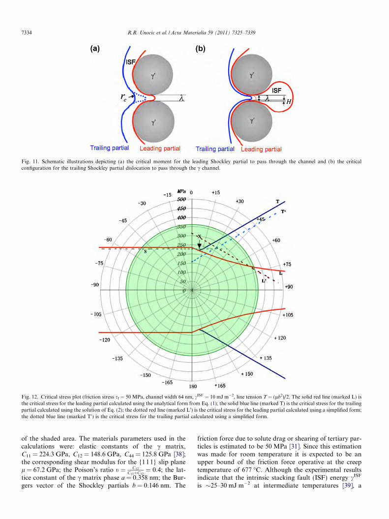
Fig. 11. Schematic illustrations depicting (a) the critical moment for the leading Shockley partial to pass through the channel and (b) the criticalconfiguration for the trailing Shockley partial dislocation to pass through the c channel.
Fig. 12. Critical stress plot (friction stress sf = 50 MPa, channel width 64 nm, cISF = 10 mJ m�2, line tension T = (lb2)/2. The solid red line (marked L) isthe critical stress for the leading partial calculated using the analytical form from Eq. (1); the solid blue line (marked T) is the critical stress for the trailingpartial calculated using the solution of Eq. (2); the dotted red line (marked L0) is the critical stress for the leading partial calculated using a simplified form;the dotted blue line (marked T0) is the critical stress for the trailing partial calculated using a simplified form.
7334 R.R. Unocic et al. / Acta Materialia 59 (2011) 7325–7339
more recent quantitative analysis of the Shockley partialdissociation suggests that cISF � 10 mJ m�2 [31]. ThuscISF = 10 mJ m�2 was chosen for the calculations. For sim-plicity the line tension was assumed to be T = (lb2/2)regardless of its character (edge or screw). Fig. 12 showsthe calculation results obtained for a c channel width of64 nm, which corresponds well with the average channelwidth measured experimentally. The red curve (markedL) is the critical stress for the leading partial to passthrough the channel, while the blue curve (marked T) isthe critical stress for the trailing partial to pass through.It can be seen from Fig. 12 that when the resolved shearstress on the leading partial becomes smaller than that onthe trailing one (h < 0) the two curves collapse, indicatingno decorrelated motion.
For a shear stress level of 362 MPa, as long as the angleh between the shear stress direction and the full dislocationBurgers vector direction is between +70� and +33�, decor-related motion of partials is expected because the leadingpartial can go through the 64 nm channel while the trailingpartial cannot. For angles from +33� to the branchingpoint of the curve (marked X on the plot, around +9�)both dislocations can go through the channel, althoughthe leading one still has a higher resolved stress, whichmeans it moves faster than the trailing one. In this case dec-orrelated motion is still possible, but depends on the differ-ence between the critical stress for the leading and trailingpartials. For h between +9� to �53� the partials will passthrough the channel together as the trailing one pushesthe leading one, and thus no decorrelated motion will occurand shearing by perfect a/2h110i dislocations should dom-inate the deformation process. For h between �53� and�90� no dislocation is able to pass through the channelat this stress level.
The decorrelation diagram with respect to stress orienta-tion has mirror symmetry relative to the normal of thea/2h110i full Burgers vector (the dislocation will movefrom the right to the left in this case, because of reversalof the in-plane shear stress orientation). Hence, there willbe large asymmetry for a given slip vector depending uponthe sign of the applied shear stress. This asymmetry isbrought about by the reversed role of the leading and trail-ing Shockley partials. Moreover, for a {111} slip planethere are three co-planar a/2h11 0i dislocations, AB, BC,and AC, whose Burgers vectors are 120� apart. By consid-ering the dissociation of all three types of full dislocationsthe probability of observing decorrelated dislocationmotion for a random orientated 362 MPa in-plane shearstress is about 78% for an average channel width of 64 nm.
Douin et al. [40] also proposed a set of simple analyticalforms to describe the dissociation process that provides thecritical stress of the leading, trailing, and full dislocations.The results are plotted in Fig. 12 (incorporating the addi-tional solute drag friction stress sf) as dashed lines (the linefor leading dislocation is marked L0, the line for trailingdislocation is marked T0, and the line for full dislocationis marked S, within the �90� < h 6 90� region). Clear dis-
agreements exist between the two calculation results. Com-pared with Eq. (1) the critical stress calculated for line L0
does not take into account the assistance from the trailingdislocation through elastic interaction. Thus Eq. (1) gives alower critical stress when h 6 60�. However, when h > 60�(for �90� < h 6 90�, when Ad is still defined as the “leadingpartial”) the resolved shear stress on the trailing partial dB
becomes negative, which means that dB is driven to movein the opposite direction with respect to Ad. In this casethe scenario shown in Fig. 11a is no longer accuratebecause the trailing partial tends to move away from theleading partial. Under this condition the critical stress cal-culated for line L0, which is established for large separationdistances between the partials, can better describe the crit-ical stress for the leading partial. As for the trailing dislo-cation, the critical stress calculated for line T0 does nottake into account the reduction in effective channel widthdue to the segments laid by the leading partial, which inturn underestimates the critical stress level.
4.1.4. Effect of microstructure on dislocation dissociation and
microtwinningPrevious work has shown that for deformation condi-
tions that produce microtwins in the finer scale precipitatemicrostructure considered in this work a different deforma-tion mode appears to be dominant for a coarser precipitatemicrostructure developed by a slower cooling rate from thesupersolvus temperature [41]. For this latter microstruc-ture, which simulates that in the “bore” region of a turbinedisk, deformation occurs by intense a/2h110i dislocationactivity in the matrix, with occasional shearing of the pre-cipitates by superlattice intrinsic or extrinsic stackingfaults. Thus for this coarser microstructure dislocation dec-orrelation does not seem to occur. Rather, matrix perfectdislocations seem to retain their ability to percolatethrough the c channels. The analytical model developedabove provides an insight into this microstructure effect.
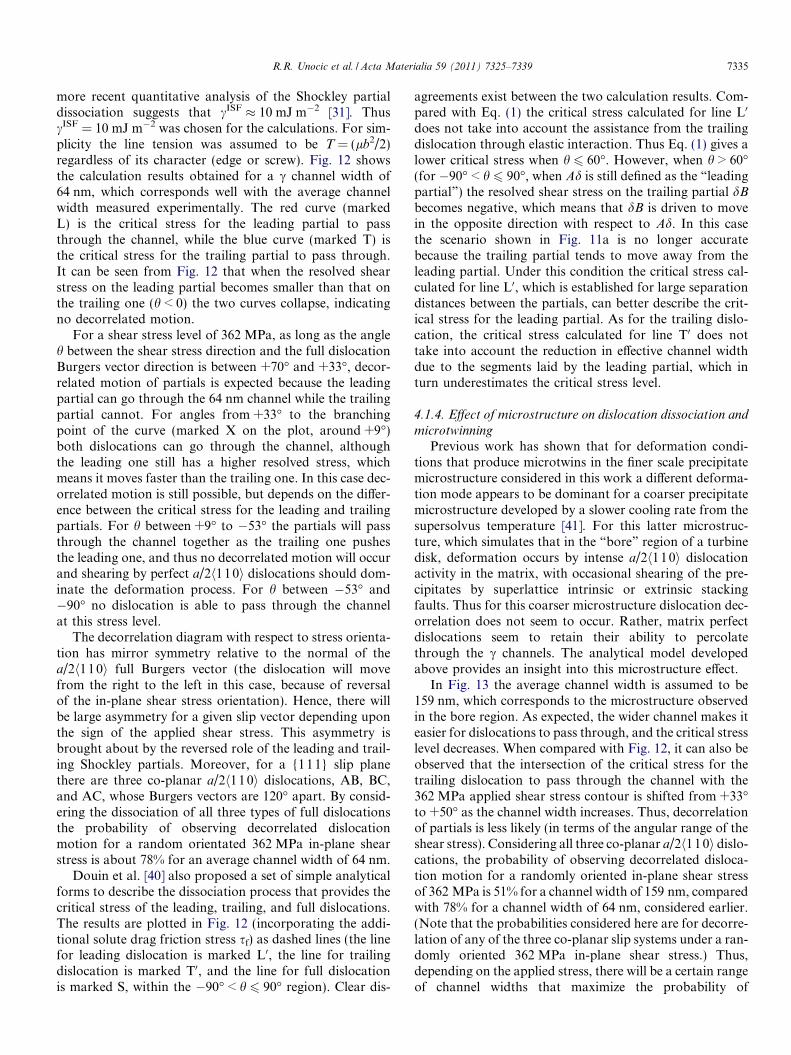
In Fig. 13 the average channel width is assumed to be159 nm, which corresponds to the microstructure observedin the bore region. As expected, the wider channel makes iteasier for dislocations to pass through, and the critical stresslevel decreases. When compared with Fig. 12, it can also beobserved that the intersection of the critical stress for thetrailing dislocation to pass through the channel with the362 MPa applied shear stress contour is shifted from +33�to +50� as the channel width increases. Thus, decorrelationof partials is less likely (in terms of the angular range of theshear stress). Considering all three co-planar a/2h11 0i dislo-cations, the probability of observing decorrelated disloca-tion motion for a randomly oriented in-plane shear stressof 362 MPa is 51% for a channel width of 159 nm, comparedwith 78% for a channel width of 64 nm, considered earlier.(Note that the probabilities considered here are for decorre-lation of any of the three co-planar slip systems under a ran-domly oriented 362 MPa in-plane shear stress.) Thus,depending on the applied stress, there will be a certain rangeof channel widths that maximize the probability of
R.R. Unocic et al. / Acta Materialia 59 (2011) 7325–7339 7335

decorrelated dislocation motion. For instance, if the in-planestress is 200 MPa instead of 362 MPa, then for a channelwidth of 64 nm even the leading partial dislocation cannotpass though. For a channel width of 159 nm dissociation isstill possible. Using these analytical formulae we may iden-tify the optimal stress level for a given microstructure, orspecify target microstructures for a given applied stress, thatwill favor matrix dislocations or microtwinning as the dom-inant deformation mode.
4.2. Transition from stacking faults to microtwins
A comprehensive review of deformation twinning hasbeen provided by Christian and Mahajan [19]. Possibilitiesfor the creation of microtwins from intrinsic matrix stack-ing fault structures have been identified. The pole mecha-nism has been proposed to describe twinning in fcccrystals [42]. In this model it is envisioned that a twin isformed from a perfect a/2h110i dislocation that acts asan anchor point where the twinning dislocation (a/6h112iShockley partial) sweeps out on {111} glide planes androtates about the pole to produce the twin. Alternatively,in the model proposed by Mahajan and Chin [43] twoco-planar a/2h11 0i dislocations with different Burgers vec-tors are envisioned to react and form three identical Shock-ley partial dislocations on adjacent {111} glide planes,thereby acting as the nucleus of a three layer twin. Fromthe limited experimental evidence of microtwinning inpolycrystalline c0 strengthened superalloys investigatedrecently [14–16] it appears that all of the a/2h110i disloca-tions that are observed to dissociate into Shockley partialdislocations have the same Burgers vector. Accordingly,these observations suggest that the microtwinning mecha-nism in these alloys differs from that proposed by Mahajanand Chin. Furthermore, in the double cross-slip model pro-posed by Pirouz a single screw oriented a/2h110i disloca-tion dissociates into two Shockley partial dislocations[44]. Similarly to a Frank–Read source, the large shearstress imposed on the leading Shockley partial dislocationwill bow out and create an intrinsic stacking fault. As the
leading Shockley partial recombines with the static, trailingpartial the a/2h110i dislocation that is once again createdcan cross-slip (along its screw orientation) to an adjacent{111} plane, then redissociate into Shockley partial dislo-cations in the same manner as the dissociation on the initial{111} plane. If this operation were to be repeated on mul-tiple adjacent {111} planes then Shockley partial disloca-tions possessing the same Burgers vector would beoperative, and a microtwin could potentially develop.Based on the present work it is impossible to definitivelyvalidate this mechanism, however, it is noted that thismechanism is consistent with the operation of singlea/2h110i slip systems as the source of the twins.
The present observation, that extended intrinsic faultsform in the c matrix preceding the onset of microtwinning,brings to bear another possibility for microtwin formation.It has been shown that these intrinsic faults form from thedissociation of a/2h1 10i dislocations that originate nearintragranular carbides and intergranular carbides/borides.Under appropriate shear stress conditions the matrix dislo-cations undergo decorrelation, with the leading partial dis-location percolating between the secondary c0 particles andlaying out large areas of intrinsic stacking faults. Withthese intrinsic stacking faults established, the subsequentinteraction of another matrix dislocation will create a sce-nario such as that illustrated in Fig. 14. Here it is envi-sioned that the same a/2h110i dislocation type cross-slipsonto the intrinsic stacking fault plane, then dissociates.As the leading partial of this second dislocation drives for-ward it creates an extrinsic stacking fault in the matrix. Asthis partial reaches locations where the first leading partialhas been arrested at c0 particles, the pair of identical Shock-ley partials are then able to traverse c0 via reorder-mediatedshearing [22]. This process will result in the removal of theShockley partial loops surrounding the c0 particles, asobserved for instance in Fig. 7, and the creation of SESFin the sheared c0 particles following reordering. Repetitionof this process of matrix dislocation cross-slip, extension,and reorder-mediated shearing would enable thickeningof the extrinsic stacking faults/SESF into multilayer
Fig. 13. Critical stress plot (friction stress sf = 50 MPa, channel width 159 nm, cISF = 10 mJ m�2, a = 1, line tension T = (lb2)/2. The solid red line is thecritical stress for the leading partial calculated using the analytical form from Eq. (1); the solid blue line is the critical stress for the trailing partialcalculated using the solution of Eq. (2).
7336 R.R. Unocic et al. / Acta Materialia 59 (2011) 7325–7339

microtwins. This scenario is also consistent with the obser-vation of microtwins in the absence of significant second-ary slip system activity [45]. Clearly, the trailing Shockleypartials that do not participate in the forward shearing pro-cess would accumulate near the origin of the twins. Theirmutual stress fields could eventually inhibit further thicken-ing of the microtwins by this cross-slip process. This mayprovide an explanation for the predominance of thinmicrotwins, with few as thick as that shown in Fig. 4c.
5. Conclusions
Through a detailed TEM characterization study on theearly stages of creep deformation in a c0 strengthened Ni-
based superalloy it was possible to identify discrete loca-tions where deformation microtwins may have nucleated.Microtwinning is an important creep deformation modeat low stress and intermediate temperatures (650–750 �C).It was found that carbides and borides, which are either sit-uated at the grain boundaries or within the grain interiors,acted as sources for a/2h11 0i matrix dislocations. At smallstrain levels matrix dislocations are frequently observed todissociate (i.e. decorrelate) into Shockley partial disloca-tions, creating broad intrinsic stacking faults in the cmatrix. Under similar creep conditions but larger strainlevels microtwinning is observed to dominate the deforma-tion. Thus matrix dislocation decorrelation appears to be akey precursor to microtwinning.
Fig. 14. Possible scenario for transition from dissociated a/2h110i type dislocations and decorrelated leading (L1) and trailing (T1) Shockley partialbounding matrix stacking faults into microtwins through a sequence of cross-slip and dissociation steps of subsequent a/2h110i dislocations. After c0 is (a)looped by the leading Shockley partial, the key steps are (b and c) the approach and cross-slip of a second a/2h110i dislocation, (d) dissociation of thesecond a/2h110i dislocation (D2) on the {111} plane adjacent to the stacking fault, (e) cooperative shearing of c0 by two Shockley partials by reorder-mediated motion, creating superlattice extrinsic stacking in c0 and an extrinsic stacking fault in the matrix, (f) approach of a third a/2h110i dislocation(D3). Repetition of this process would enable thickening into microtwins.
R.R. Unocic et al. / Acta Materialia 59 (2011) 7325–7339 7337

The decorrelation process is driven by the relative forcesacting on the two Shockley partial dislocations of a perfecta/2h110i -type matrix dislocation in the narrow confines ofthe c matrix channels, since the c precipitates cannot besheared by the leading Shockley partials. A detailed analy-sis of these forces has been performed using computer sim-ulations based on a phase field dislocation model, uponwhich an analytical model was also developed. In the anal-ysis a consistent picture emerges demonstrating the possi-bility of a rich variety of behaviors depending on severalfactors, including orientation of the applied shear stress rel-ative to the dislocation Burgers vectors, the c channelwidth, and the matrix stacking fault energy. The modelspredict that decorrelation can occur at low stress levels rel-ative to other possible processes (such as Orowan bowingaround particles) when the applied shear stress is suitablyoriented so as to create a larger force on the leading Shock-ley partial dislocation. This result provides a natural expla-nation for the observation of matrix stacking faultsdominating the substructure of many grains at small strainlevels. Several possible scenarios for the subsequent thick-ening from intrinsic stacking faults into microtwins havealso been discussed, including repeated cross-slip and dis-sociation of matrix dislocations onto pre-existing stackingfaults.
Acknowledgements
Acknowledgement is given to support from the US AirForce sponsored Metals Affordability Initiative (MAI) pro-ject entitled “Durable high temperature disk material”.Team members include Pratt & Whitney, GE Aviation,Georgia Institute of Technology, The Ohio State Univer-sity, and the University of Rhode Island. The authorswould like to thank the Air Force Office of Scientific Re-search for their support under the AFOSR MEANS II pro-gram. R.R.U. would like to acknowledge support from theAlvin M. Weinberg Fellowship of Oak Ridge NationalLaboratory, managed by UT-Battelle for the US Depart-ment of Energy.
Appendix A. Analytical model of dislocation dissociation
During the critical moment when the leading partial isattempting to bow through a c channel between two c0 par-ticles, as indicated in Fig. 11a, the resolved shear stress onthe leading partial is s cosðhlÞ and that on the trailing par-tial is s cosðhtÞ, where hl is the angle between the appliedstress and the Burgers vector of the leading partial and ht
is the angle between the stress and the Burgers vector ofthe trailing partial, as shown in Fig. 12. If the anglebetween the stress and the Burgers vector of the full dislo-cation is h, then ht = 30� + h and hl = 30� � h.
The leading partial experiences a repulsion force fd fromthe elastic interaction with the trailing partial and a dragfrom the intrinsic stacking fault between them. Accordingto the Orowan equation [36] the critical resolved shear
stress on the leading particle slcrss for passage through the
c channel between two c0 particles is given by the equation:
f d
bþ sl
crss cosðhlÞ � sf ¼a � lb
kðA1Þ
where k is the channel width. Assuming that the trailingsegment close to the channel has a local curvature of rt
(see arrow in Fig. 11a), the force balance on the trailingone is:
slcrss cosðhtÞ � sf �
a � lb2rt
¼ f d
bðA2Þ
The local curvature of the trailing partial at this criticalmoment can be estimated if we assume that the resolvedshear stress is much greater than the friction force, i.e.
slcrss
a � lb� 1
cosðhlÞ1
k¼ 1
cosðhtÞ1
2rt
ðA3Þ
Thus
2rt ¼ kcosðhlÞcosðhtÞ
ðA4Þ
when cosðhlÞ > cosðhtÞ. When cosðhlÞ 6 cosðhtÞ the re-solved shear stress on the leading partial is lower than orequal to that on the trailing one and hence the trailing par-tial will push the leading one. In this case the two disloca-tions will have similar curvatures at the critical moment(indicated in Fig. 11a by the dotted line for the trailing dis-location), i.e.
2rt � k ðA5ÞWhen rt is known the critical in-plane stress for the lead-
ing partial to bow through the channel is:
slcrss ¼
2sf
cosðhlÞ þ cosðhtÞþ alb
k cosðhlÞfor cosðhlÞ > cosðhtÞ
slcrss ¼
2
cosðhlÞ þ cosðhtÞalbkþ sf
� �
for cosðhlÞ 6 cosðhtÞ ðA6Þ
When the trailing dislocation attempts to pass throughthe channel, no matter whether the leading one has alreadypassed through or is just moving together with and right infront of the trailing one when cosðhlÞ 6 cosðhtÞ, the leadingpartial must have already laid two segments at the c/c0
interface inside the channel as illustrated in Fig. 11b. Thusthe effective width of the channel is reduced for the trailingone due to the repulsive force of the deposited segments ofthe leading partial. The distance H between the depositedleading particle segments in the channel and the trailingdislocation can be calculated using the equation:
stcrss cosðhtÞbþ cISF ¼ lb2
4pHð1� mÞ ðA7Þ
which represents the force balance between the resolvedshear stress, the attractive force from the intrinsic stacking
7338 R.R. Unocic et al. / Acta Materialia 59 (2011) 7325–7339
fault and the repulsive force from the leading partial seg-ment. st
crss is the critical resolved shear stress for the trailingpartial to pass through and m is the Poisson’s ratio.
Considering that the effective channel width for the trail-ing partial is reduced to k � 2H, the force balance at thecritical moment for the trailing partial to bow throughthe channel is:
stcrss cosðhtÞ ¼ sf þ
a � lbk� 2H
� cISF
bðA8Þ
As this is a quadratic function of stcrss (note that H is a
function of stcrss) an analytical solution can be easily
obtained. The other condition required for decorrelatedmotion is that st
crss P slcrss. If st
crss < slcrss the trailing partial
will push the leading one passing through the channel moreor less simultaneously and thus there is no decorrelatedmotion.
References
[1] Pollock TM, Argon AS. Acta Metall Mater 1992;42(1):1.[2] Levarant GR, Kear BH. Metall Trans 1970;1(2):491.[3] Kear BH, Oblak JM, Giamei AF. Metall Trans 1970;1(9):2477.[4] Link T, Feller-Kniepmeier M. Metall Trans 1992;23A:99.[5] Rae CMF, Reed RC. Acta Mater 2007;55(3):1067.[6] Caron P, Khan T, Veyssiere P. Philos Mag A 1988;57:859.[7] Decamps B, Morton AJ, Condat M. Philos Mag A 1991;64:641.[8] Bonnet R, Ati A. Scripta Metall Mater 1991;25:1553.[9] Guimier A, Strudel JL. In: Proceedings of the 2nd international
conference on the strength of metals and alloys, vol. 3; 1970. p. 1145.[10] Ardakani MG, McLean M, Shollock BA. Acta Mater
1999;47(9):2593.[11] Knowles DM, Gunturi S. Mater Sci Eng A 2002;328:223.[12] Knowles DM, Chen QZ. Mater Sci Eng A 2003;340:88.[13] Kakehi K. Scripta Mater 1999;41(5):461.[14] Viswanathan GB, Sarosi PM, Henry MF, Whitis DD, Milligan WW,
Mills MJ. Acta Mater 2005;53:3041.[15] Viswanathan GB, Karthikeyan S, Sarosi PM, Unocic RR, Mills MJ.
Philos Mag 2006;86(29–31):4823.[16] Unocic RR, Viswanathan GB, Sarosi PM, Karthikeyan S, Li J, Mills
MJ. Mater Sci Eng A 2008;483/484:25.[17] Legros M, Clement N, Caron P, Coujou A. Mater Sci Eng A
2002;337:160.[18] Honeycombe RWK. The plastic deformation of metals. Lon-
don: Edward Arnold; 1984.
[19] Christian JW, Mahajan S. Prog Mater Sci 1995;39(1/2):1.[20] Kolbe M. Mater Sci Eng A 2001;319:383.[21] Karthikeyan S, Unocic RR, Sarosi PM, Viswanathan GB, Whitis
DD, Mills MJ. Scripta Mater 2006;54(6):1157.[22] Kovarik L, Unocic RR, Li J, Sarosi PM, Shen C, Wang Y, et al. Prog
Mater Sci 2009;54(6):839.[23] Zhou N, Shen C, Mills MJ, Li J, Wang Y. Acta Mater
2011;59(9):3484.[24] Mourer DP, Williams JL. In: Green KA, Pollock TM, Harada H,
Howson TE, Reed RC, Schirra JJ, editors. 10th Internationalsymposium on superalloys, Champion, PA; 2004. p. 401.
[25] Sarosi PM, Wang B, Simmons JP, Wang Y, Mills MJ. Scripta Mater.2007;57:767.
[26] Wlodek ST, Kelly M, Alden DA. In: Kissinger RD, Deye DJ, AntonDL, Cetel AD, Nathal MV, Pollock, et al., editors. 8th Internationalsymposium on superalloys, Champion, PA; 1996. p. 129.
[27] Sarosi PM, Viswanathan GB, Mills MJ. Scripta Mater 2006;55:727.[28] Wlodek ST. In: Fuchs GE, Dannemann KA, Deragon TA, editors.
Long term stability of high temperature materials. Warrendale(PA): TMS; 1999. p. 3.
[29] Donachie MJ, Donachie SJ. Superalloys: a technical guide. MaterialsPark (OH): ASM International; 2002.
[30] Williams DB, Carter CB. Transmission electron microscopy. NewYork: Plenum Press; 1996. p. 381.
[31] Raujol S, Benyoucef M, Locq D, Caron P, Pettinari F, Clement N,et al. Philos Mag 2006;86(9):1189.
[32] Vitek V. Philos Mag 1968;18(154):773.[33] Shen C, Wang Y. Acta Mater 2003;51(9):2595.[34] Shen C, Wang Y. Acta Mater 2004;52(3):683.[35] Jouiad M, Pettinari E, Clement N, Coujou A. Philos Mag
1999;79(11):2591.[36] Orowan E, Zeits F. Physik 1934;89:605–59.[37] Wang YU, Jin TM, Cuitino AM, Khachturyan AG. Acta Mater
2001;49(10):1847.[38] Kayser FX, Stassis C. Phys Stat Sol 1981;64(1):335.[39] Pettinari F, Douin J, Saada G, Caron P, Coujou A, Clement N.
Mater Sci Eng 2002;325:511.[40] Douin J, Pettinari-Sturmel F, Coujou A. Acta Mater 2007;55:6453.[41] Unocic RR, Kovarik L, Shen C, Sarosi PM, Wang Y, Li J, et al. In:
Reed RC, Green KA, Gabb TP, Fahrmann MG, Huron ES, editors.11th International symposium on superalloys, Champion, PA; 2008.p. 377.
[42] Venables JA. Philos Mag 1961;6:379.[43] Mahajan S, Chin GY. Acta Metall 1973;21:1353.[44] Pirouz P. Scripta Metall 1987;21:1463.[45] Unocic RR. PhD dissertation. The Ohio State University; 2008.
R.R. Unocic et al. / Acta Materialia 59 (2011) 7325–7339 7339


![Decorrelation-based Piecewise Digital Predistortion ... · proposed closed-loop learning algorithm is based on a compu-tationally simple decorrelation-based learning rule [10], which](https://img.dokumen.tips/doc/110x75/60349bfa1bd7bc54b93f6fa4/decorrelation-based-piecewise-digital-predistortion-proposed-closed-loop-learning.jpg)