Embed Size (px)
Citation preview
HAL Id: jpa-00213130https://hal.archives-ouvertes.fr/jpa-00213130
Submitted on 1 Jan 1966
HAL is a multi-disciplinary open accessarchive for the deposit and dissemination of sci-entific research documents, whether they are pub-lished or not. The documents may come fromteaching and research institutions in France orabroad, or from public or private research centers.
L’archive ouverte pluridisciplinaire HAL, estdestinée au dépôt et à la diffusion de documentsscientifiques de niveau recherche, publiés ou non,émanant des établissements d’enseignement et derecherche français ou étrangers, des laboratoirespublics ou privés.
DISLOCATION DIPOLES AND DISLOCATIONLOOPSF. Kroupa
To cite this version:F. Kroupa. DISLOCATION DIPOLES AND DISLOCATION LOOPS. Journal de Physique Collo-ques, 1966, 27 (C3), pp.C3-154-C3-167. �10.1051/jphyscol:1966320�. �jpa-00213130�
JOURNAL DE PHYSIQUE Colloque C 3, supplkment au no 7-8, Tome 27, juillet-aolit 1966, page C 3-154
DISLOCATION DIPOLES AND DISLOCATION LOOPS
F. KROUPA Institute of Physics, Czechosl. Acad. Sci. Vinie.na 7, Prague 2
ResumB. - L'auteur presente les id& thkoriques de base relatives aux proprietes de deux configurations de dislocation particulikres, les dipales de dislocation et les boucles de dislocation prismatiques. I1 donne aussi ses rksultats recents fondes principalement sur l'application du modhle du continuum klastique a ces dkfauts cristallins. I1 discute l'influence des dip6les et des boucles sur diverses propriCtBs mtcaniques.
Abstract. -Basic theoretical ideas on the properties of two special dislocation configurations, dis- location dipoles and prismatic dislocation loops, are presented. Some of the author's recent results, based mostly on the application of the model of elastic continuum on these crystalline defects, are also given. The influence of dipoles and loops on different mechanical properties is discussed.
1. Introducticm. - Basic theoretical ideas on the properties of two special dislocation arrangements will be reviewed : dislocation dipoles (i. e. pairs of parallel dislocations with opposite Burgers vectors) and prismatic dislocation loops (i. e. dislocation loops with Burgers vectors that do not lie in the loop pla- nes). These arrangements have been observed in crystalline materials by transmission electron micros- copy after different kinds of treatment : the dipoles after plastic deformation, the prismatic loops after quenching, irradiation, and after plastic deforma- tion.
The density of these defects is often very high. Therefore, they can influence considerably the mecha- nical as well as some other physical properties of crystalline materials.
Some properties of the dipoles and prismatic loops are rather similar : e. g. their stress field decreases more quickly with distance than that of straight indi- vidual dislocations, which leads to a much weaker mutual elastic interaction and to the possibility of formation of a very high local density of these defects ; both of them can disappear by climbing at elevated temperatures. In fact, dipoles can be described as elongated prismatic loops. Therefore, it may be useful to review both these defects simultaneously.
model of elastic continuum, will be pointed out. Recently, the elastic properties of dislocation loops have been similarly reviewed by the author [2].
2. Formation of dipoles and prismatic loops. - The actual forms of dislocations differ considerably from the idealization mostly used in the theory of dislocations - from the straight infinite dislocation.
Dislocations in as-grown or in well annealed single crystal form two-dimensional nets in the mosaic block boundaries and three-dimensional nets inside the mosaic blocks. The main part of the dislocations formed during the plastic deformation or during the different thermal treatment is in the form of loops.
By a dislocation loop we understand a dislocation whose dislocation line is closed inside the crystal.
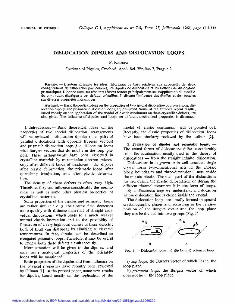
The dislocation loops are usually formed in special crystallographic planes and according to the relative position of the Burgers vector and the loop plane they can be divided into two groups (Fig. 1) :
-
More attention will be given to the dipoles, and only some analogical properties of the prismatic FIG. 1. - Dislocation loops : a) slip loop, 6) prismatic loop.
loops will be mentioned Basic properties of the dipoles and their influence on i) slip loops, the Burgers vector of which lies in the
the physical properties have recently been reviewed loop plane, by Gilman [l]. In the present paper, some new results ii) prismatic loops, the Burgers vector of which for dipoles, based mostly on the application of the does not lie in the loop plane.
Article published online by EDP Sciences and available at http://dx.doi.org/10.1051/jphyscol:1966320
DISLOCATION DIPOLES AND DISLOCATION LOOPS C 3 . 15.5
Siip loops are usually formed in slip planes under external shear stress, e. g. by Frank-Read source mechanism or by stress concentration on non-homo- geneities. These loops can further extend by gliding and reach dimensions of a few p up to 100 p ; in single crystals of pure metals they may be even larger.
During the expansion of loops in the slip planes, dislocation dpoles are formed by different processes [3]. Two of them seem to be most important :
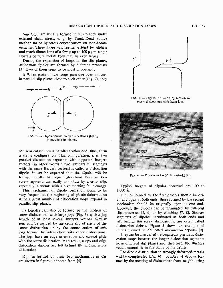
i) When parts of two loops pass one over another in parallel slip planes close to each other (Fig. 2), they
FIG. 2. - Dipole formation by dislocations gliding in parallel slip planes.
can reorientate into a parallel section and, thus, form a stable configuration. This configuration, i. e. two parallel dislocation segments with opposite Burgers vectors (in other words : two antiparallel segments with the same Burgers vectors) is called a dislocation dipole. It can be expected that the dipoles will be formed mostly by edge dislocations because two
FIG. 3. - Dipole formation by motion of screw dislocations with large jogs.
Re. 4. - Dipoles in Cu (Z. S. Basinski [4]).
screw segments can easily annihilate by a cross slip, especially in metals with a high stacking fault energy. Typical heights of dipoles observed are 100 to
This mechanism of dipole formation seems to be l000 A. very frequent at the beginning of plastic deformation Dipoles formed by the first process should be ori- when a great number of dislocation loops expand in ginally open at both ends, those formed by the second parallel slip planes. mechanism should be originally open at one end.
ii) Dipoles can also be formed by the motion of However, the dipoles can be terminated by different
screw dislocations with large jogs (Fig. 3) with a jog slip processes [5, 61 or by climbing [7, 81. Shorter
length of at least several Burgers vectors. Similar segments of dipoles, terminated at both ends and
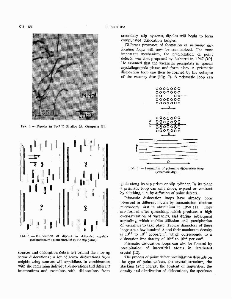
jogs can be formed by the cross slip of parts of the left behind the screw dislocations, are often called dislocation debris. Figure 5 shows an example of screw dislocation or by the concentration of unit
jogs formed by intersection with other dislocations. debris formed in deformed silicon-iron crystals [9].
The jogs have an edge orientation and cannot glide They can be also called (( elongated n prismatic dislo-
with the screw dislocation. As a result, cusps and edge cation loops because the longer dislocation segments
dislocation dipoles are left behind the gliding screw lie in different slip planes and, therefore, the Burgers vector cannot lie in the plane of the debris. dislocation.
The dipole distribution in strongly deformed metals Dipoles formed by these two mechanisms in Cu will be complicated (Fig. 6 ) : bundles of dipoles for-
are shown in figure 4 adopted from [4]. med by the meeting of dislocations from neighbouring
C 3 - 156 F. KROUPA
FIG. 5. - Dipoles in Fe-3 % Si alloy (A. Gemperle [9]).
FIG. 6. -Distribution of dipoles in deformed crystals (schematically ; plane parallel to the slip plane).
sources and dislocation debris left behind the moving screw dislocations ; a lot of screw dislocations from neighbouring sources will annihilate. In combination with the remaining individual dislocations and different intersections and reactions with dislocations from
secondary slip systems, dipoles will begin to form complicated dislocation tangles.
Different processes of formation of prismatic dis- location loops will now be summarized. The most important mechanism, the precipitation of point defects, was first proposed by Nabarro in 1947 [IO]. He assumed that the vacancies precipitate in special crystallographic planes and form discs. A prismatic dislocation loop can then be formed by the collapse of the vacancy disc (Fig. 7). A prismatic loop can
FIG. 7. - Formation of prismatic dislocation loop (schematically).
glide along its slip prism or slip cylinder. In its plane a prismatic loop can only move, expand or contract by climbing, i. e. by diffusion of point defects.
Prismatic dislocation loops have already been observed in different metals by transmission electron microscopy, first in aluminium in 1958 1111. They are formed after quenching, which produces a high over-saturation of vacancies, and during subsequent annealing, which enables diffusion and precipitation of vacancies to take place. Typical diameters of these loops are a few hundred A and their maximum density is 1015 to 1016 loops/cm3, which corresponds to a dislocation line density of 10'' to 10" per cm2.
Prismatic dislocation loops can also be formed by precipitation of interstitial atoms in irradiated crystal [12].
The process of point defect precipitation depends on the type of point defects, the crystal structure, the stacking fault energy, the content of impurities, the density and distribution of dislocations, the specimen
DISLOCATION DIPOLES AND DISLOCATION LOOPS C 3 - 157
or grain size, and on different conditions, e. g. the Surprisingly, it has been recently found that in quenching temperature, quenching rate, and ageing very pure aluminium (99.999 %) pri'smatic lbops temperature. with stacking faults and with radii up to l000 A
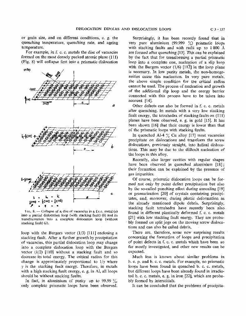
For example, in f. c. c. metals the disc of vacancies are formed after quenching [13]. This can be explained formed on the most densely packed atomic plane (1 11) by the fact that for transforming a partial prismatic (Fig. S) will collapse first into a prismatic dislocation loop into a complete one, nucleation of a slip loop
with the Burgers vector (116) [l121 in the loop plane (4 TO) is necessary. In low purity metals, the non-homoge-
neities cause this nucleation. In very pure metals,
FIG. 8. - Collapse of a disc of vacancies in a f.c.c. metal (a) into a partial dislocation loop (with stacking fault) (b) and its transformation into a complete dislocation loop (without stacking fault) (c).
loop with the Burgers vector (113) [l 1 l ] enclosing a stacking fault. After a further growth by precipitation of vacancies, this partial dislocation loop may change into a complete dislocation loop with the Burgers vector (112) [l101 without a stacking fault and so decrease its total energy. The critical radius for this change is approximately proportional to lly where y is the stacking fault energy. Therefore, in metals with a high stacking fault energy, e. g. in Al, all loops should be without stacking faults.
In fact, in aluminium of purity up to 99.99 %, only complete prismatic loops have been observed.
the above simple condition for the critical radius cannot be used. The process of nucleation and growth of the additional slip loop and the energy barrier connected with this process have to be taken into account [14].
Other defects can also be formed in f. c. c. metals after quenching. In metals with a very low stacking fault energy, the tetrahedra of stacking faults on (1 11) planes have been observed, e. g. in gold [15]. It has been shown [l61 that their energy is lower than that of the prismatic loops with stacking faults.
In quenched A1-4 % Cu alloy [l71 most vacancies precipitate on dislocations and transform the screw dislocations, previously straight, into helical disloca- tions. This may be due to the difficult nucleation of the loops in this alloy.
Recently, also larger cavities with regular shapes have been observed in quenched aluminium [l81 ; their formation can be explained by the presence of gas impurities.
Of course, prismatic dislocation loops can be for- med not only by point defect precipitation but also by the so-called punching effect during annealing [l91 or pressurization [20] of crystals containing precipi- tates, and, moreover, during plastic deformation as the already mentioned dipole debris. Surprisingly, stacking fault tetrahedra have recently been also found in different plastically deformed f. c. c. metals [21] with low stacking fault energy. They are proba- bly formed on split jogs on the moving screw disloca- tions and can also be called debris.
There are, therefore, some new surprising results concerning the formation of loops and precipitation of point defects in f. c. c. metals which have been so far mostly investigated, and other new results can be expected.
Much less is known about similar problems in h. c. p. and b. c. c. metals. For example, no prismatic loops have been found in quenched b. c. c. metals, but different loops have been already found in irradia- ted b. c. c. metals, e. g. in iron [22], which are proba- bly formed by interstitials.
It can be concluded that the problems of precipita-
C 3 - 1 5 8 F. KROUPA
tion of point defects are far from being completely solved and that the main interest shifts from f. c. c. to h. c. p. and especially to b. c. c. metals, similarly as in the problems of plastic deformation.
3. Basic properties of dipoles.
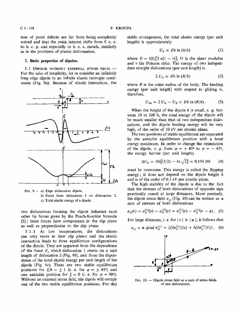
3.1 DIPOLES WITHOUT EXTERNAL STRESS FIELD. - For the sake of simplicity, let us consider an infinitely long edge dipole in an infinite elastic isotropic conti- nuum (Fig. 9a). Because of elastic interaction, the
7 1
FIG. 9. - a) Edge dislocation dipole. b) Force from dislocation 1 on dislocation 2. c) Total elastic energy of a dipole.
stable arrafigement, the total elastic energy (per unit length) is approximately
where D = Gb/[2 n(1 - v)], G is the shear modulus and v the Poisson ratio. The energy of two indepen- dent straight dislocations (per unit length) is
where R is the outer radius of the body. The binding energy (per unit length) with respect to gliding is, therefore,
When the height of the dipole h is small, e. g. bet- ween 10 to 100 b, the total energy of the dipole will be much smaller than that of two independent dislo- cations, and the dipole binding energy will be very high, of the order of 10 eV per atomic plane.
The two positions of stable equilibrium are separated by the unstable equilibrium position with a local energy maximum. In order to change the orientation of the dipole, e. g. from cp = + 45O to cp = - 4 5 O , the energy barrier (per unit length)
must be overcome. This energy is called the flipping energy; it does not depend on the dipole height h and is of the order of 0.1 eV per atomic plane.
The high stability of the dipole is due to the fact that the stresses of both dislocations of opposite sign practically cancel at large distances. More precisely, the dipole stress field crij (Fig. 10) can be written as a sum of stresses of both dislocations
(1) (2) two dislocations forming the dipole influence each oij(v) = oij (r) + aij (V) = de)(r) - o$)(r - a ) . (5) other by forces given by the Peach-Koehler formula [3] ; these forces have components in the slip plane For large distances, i. e. for ( V ( S ( a I, it follows that as well as perpendicular to the slip plane. oij = a . grad 0:;) = t(80$;'/ax) + h(aoi;)/ay) . (6)
3.1.1 At low temperatures, the dislocations can only move in their slip planes and the elastic Y interaction leads to three equilibrium configurations of the dipole. They are apparent from the dependence of the force Fx which dislocation 1 exerts on a unit length of dislocation 2 (Fig. 9b), and from the depen- dence of the total elastic energy per unit length of the dipole (Fig. 9c). There are two stable equilibrium positions for </h = & 1 (i. e. for 9 = + 450) and one unstable position for 5 = 0 (i. e. for 9 = 900). Without an external stress field, the dipole will occupy FIG. 10. - Dipole stress field as a sum of stress fields one of the two stable equilibrium positions. For this of two dislocations.
DISLOCATION DIPOLES AND DISLOCATION LOOPS
The long range dipole stress field is expressed in this equation by means of the stress gradients of one edge dislocation. Since the stress field of a dislocation decreases with the distance r as llr, it simply follows that the long range stress field of a dipole decreases as l/r2.
The stress field in the close neighbourhood of the dipole is complicated. Only the stress field at the centre of the dipole will be mentioned (Fig. 11). It is
where the + sign holds for the extensional dipoles (Fig. lla), and the - sign for the compressional dipoles (Fig. llb). The stress components ox, of both
FIG. 11. - Stress field at centre of : a) extensional dipole, b) compressional dipole.
dislocations do not cancel in the centre, on the contra- ry they add. Thus in the case of extensional dipoles there is a large tensible stress ; for h/b -- 10 to 100, ox, G120 to G/200. Consequently, places with a high density of extensional dipoles represent a wea- kening of the crystal and can become nuclei of frac- ture.
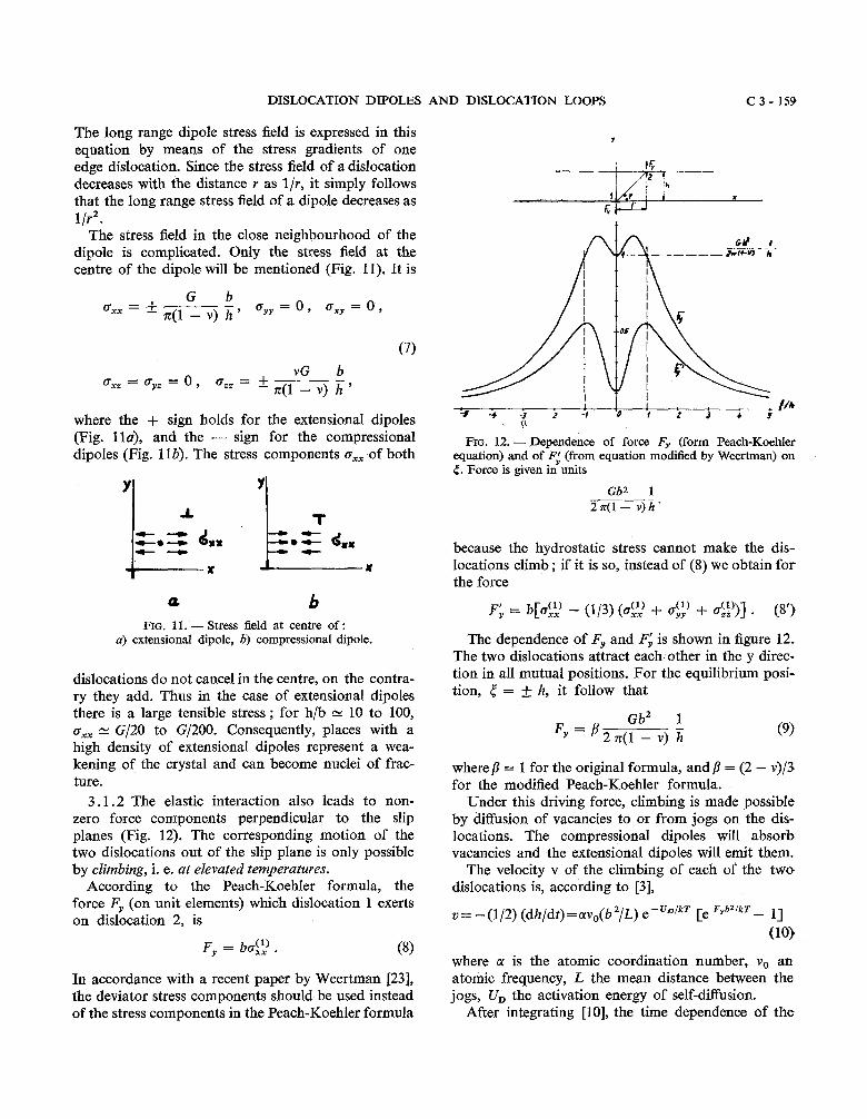
3.1.2 The elastic interaction also leads to non- zero force components perpendicular to the slip planes (Fig. 12). The corresponding motion of the two dislocations out of the slip plane is only possible by climbing, i. e. at elevated temperatures.
According to the Peach-Koehler formula, the force F, (on unit elements) which dislocation 1 exerts on dislocation 2, is
In accordance with a recent paper by Weertman [23], the deviator stress components should be used instead of the stress components in the Peach-Koehler formula
l +- * -S -i - j -2 -i '0 L t j 4 S
FIG. 12. - pependence of force F, (form Peach-Koehler equation) and of F; (from equation modified by Weertman) on 5. Force is given in units
Gb2 1 2741 - v)%'
because the hydrostatic stress cannot make the dis- locations climb ; if it is so, instead of (8) we obtain for the force
The dependence of Fy and F: is shown in figure 12. The two dislocations attract each other in the y direc- tion in all mutual positions. For the equilibrium posi- tion, 5 = f h, it follow that
where /3 = 1 for the original formula, and j3 = (2 - v)/3 for the modified Peach-Koehler formula.
Under this driving force, climbing is made possible by diffusion of vacancies to or from jogs on the dis- locations. The compressional dipoles will absorb vacancies and the extensional dipoles will emit them.
The velocity v of the climbing of each of the two dislocations is, according to [3],
where a is the atomic coordination number, v, an atomic frequency, L the mean distance between the jogs, U, the activation energy of self-diffusion.
After integrating [10], the time dependence of the
C 3 - 160 F. KROUPA
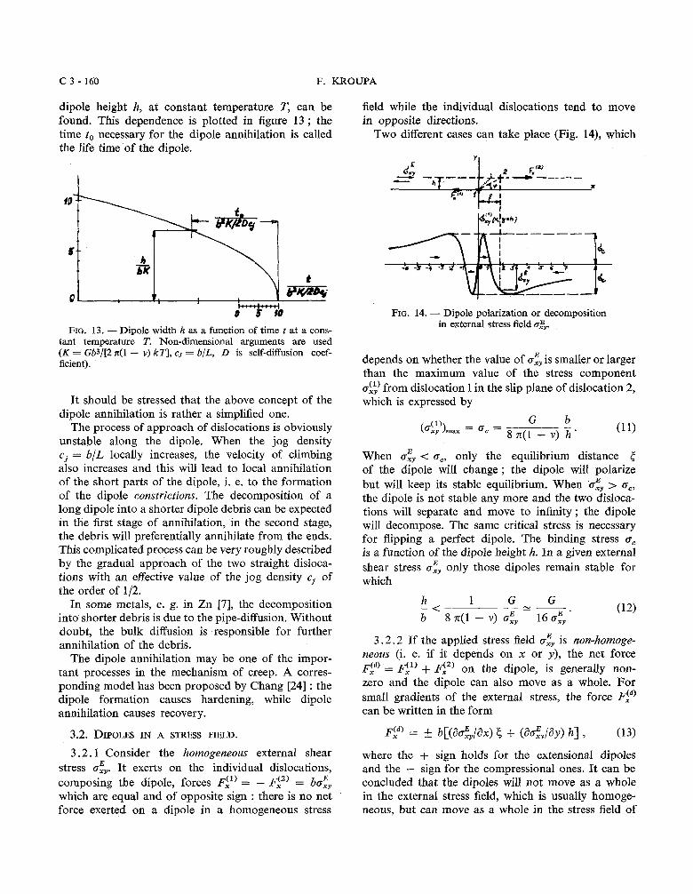
dipole height h, at constant temperature T, can be found. This dependence is plotted in figure 13 ; the time to necessary for the dipole annihilation is called the life time of the dipole.
field while the individual dislocations tend to move in opposite directions.
Two different cases can take place (Fig. 14), which
FIG. 13. - Dipole width h as a function of time t at a cons- tant temperature T. Non-dimensional arguments are used (K = Gb3/[2 x(1 - v) kT], cj = b/L, D is self-diffusion coef- ficient).
It should be stressed that the above concept of the dipole annihilation is rather a simplified one.
The process of approach of dislocations is obviously unstable along the dipole. When the jog density cj = b/L locally increases, the velocity of climbing also increases and this will lead to local annihilation of the short parts of the dipole, i. e. to the formation of the dipole constrictions. The decomposition of a long dipole into a shorter dipole debris can be expected in the first stage of annihilation, in the second stage, the debris will preferentially annihilate from the ends. This complicated process can be very roughly described by the gradual approach of the two straight disloca- tions with an effective value of the jog density cj of the order of 112.
In some metals, e. g. in Zn [7], the decomposition into shorter debris is due to the pipe-diffusion. Without doubt, the bulk diffusion is responsible for further annihilation of the debris.
The dipole annihilation may be one of the impor- tant processes in the mechanism of creep. A corres- ponding model has been proposed by Chang [24] : the dipole formation causes hardening, while dipole annihilation causes recovery.
3.2. DIPOLES IN A STRESS FIELD.
3 .2 .1 Consider the homogeneous external shear E stress ox,. It exerts on the individual dislocations,
composing the dipole, forces F:) = - F:') = boE XY
which are equal and of opposite sign : there is no net force exerted on a dipole in a homogeneous stress
FIG. 14. - Dipole polarization or decomposition in external stress field D&,.
depends on whether the value of o: is smaller or larger than the maximum value of the stress component og) from dislocation 1 in the slip plane of dislocation 2, which is expressed by
When a:, < cc, only the equilibrium distance 5 of the dipole will change ; the dipole will polarize but will keep its stable equilibrium. When o:, > a,, the dipole is not stable any more and the two disloca- tions will separate and move to infinity ; the dipole will decompose. The same critical stress is necessary for flipping a perfect dipole. The binding stress o, is a function of the dipole height h. In a given external shear stress ofy only those dipoles remain stable for which
3 .2 .2 If the applied stress field o$ is non-homoge- neous (i. e. if it depends on X or y), the net force i?id) = F:) + on the dipole, is generally non- zero and the dipole can also move as a whole. For small gradients of the external stress, the force can be written in the form
where the + sign holds for the extensional dipoles and the - sign for the compressional ones. It can be concluded that the dipoles will not move as a whole in the external stress field, which is usually homoge- neous, but can move as a whole in the stress field of
DISLOCATION DIPOLES AND DISLOCATION LOOPS C 3 - 161
other defects (especially of dislocations) which is always non-homogeneous.
4. Interaction between dipoles and other defects.
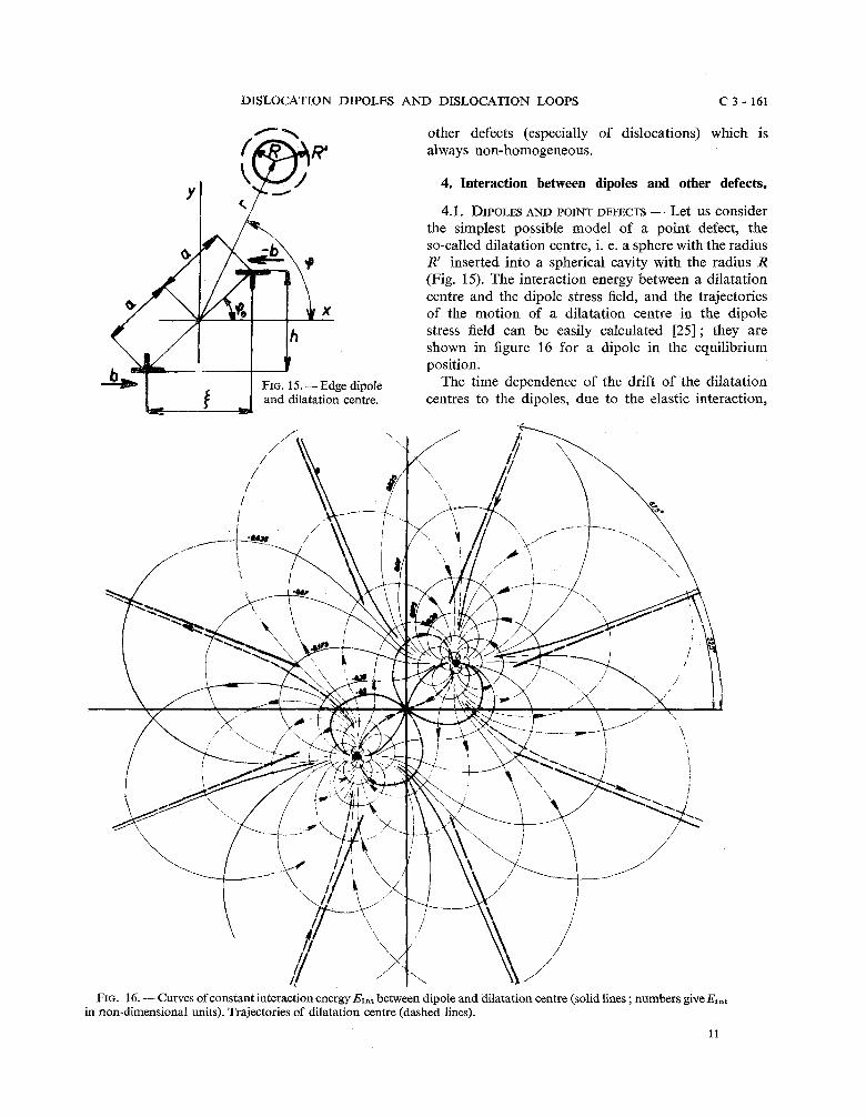
4.1. DIPOLES AND POINT DEFECTS - Let us consider the simplest possible model of a point defect, the so-called dilatation centre, i. e. a sphere with the radius R' inserted into a spherical cavity with the radius R (Fig. 15). The interaction energy between a dilatation centre and the dipole stress field, and the trajectories of the motion of a dilatation centre in the dipole stress field can be easily calculated 1251 ; they are shown in figure 16 for a dipole in the equilibrium position.
FIG. 15. -Edge dipole The time dependence of the drift of the dilatation and dilatation centre. centres to the dipoles, due to the elastic interaction,
FIG. 16. -Curves of constant interaction energy Exnt between dipole and dilatation centre (solid lines ; numbers give Eint in non-dimensional units). Trajectories of dilatation centre (dashed lines).
11
C 3 - 162 F. KROUPA
can be solved in a similar way as Cottrell and Bilby [26] have done for individual dislocations. If only the long-range dipole stress field is considered, we get the law for the dipoles in the form n N t% (where n is the number of dilatation centres, e.g. of impurities that arrive at the dipoles between the times 0 and t ) instead of the Cottrell and Bilby's law for individual dislocations, n N t 2 I 3 . It should be emphasized that these calculations based on the elastic interaction only, without taking into account the diffusion due to concentration gradients, are only valid for the initial stage of diffusion.
From our results it can be concluded that the time dependence of the diffusion of impurities to the dis- locations and, therefore, also the time dependence of ageing of some alloys depends, in the initial stage, on the dislocation distribution and, in the case of a high density of dipoles, the t% law can also be expec- ted.
4.2 DIPOLES AND STRAIGHT DISLOCATIONS. - Let US
discuss separately the cases when the dipoles and dislocations are parallel and non-parallel.
4.2.1 The elastic interaction between dipoles and parallel dislocations has recently been discussed in detail [27].
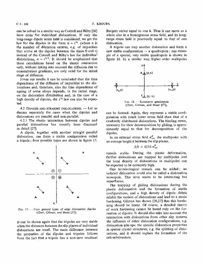
A dipole, together with another straight parallel dislocation, can form a stable configuration called a tripole ; four possible types are shown in figure 17.
FIG. 17. - Four general types of edge dislocation dipoles (Chen, Gilman, and Head [27]).
It can be shown again that the tripoles are very stable when the distances between the slip planes of individual dislocations are small. The main difference between the properties of the dipoles and tripoles follows from the fact that a tripole has a non-zero resultant
Burgers vector equal to one b. Thus it can move as a whole also in a homogenous stress field, and its long- range stress field is practically equal to that of one dislocation.
A tripole can trap another dislocation and form a new stable configuration - a quadrupole ; one exam- ple of a special, very stable quadrupole is shown in figure 18. In a similar way, higher order multipoles
FIG. 18. - Symmetric quadrupole (Chen, Gilman, and Head [27]).
can be formed. Again, they represent a stable confi- guration with much lower stress field than that of n randomly distributed dislocations. The binding stress, necessary for their decomposition by gliding, is appro- ximately equal to that for decomposition of the dipoles.
In an external stress field c:,,, the multipoles with an average height h between the slip planes,
remain stable. During the plastic deformation, further dislocations are trapped by multipoles and the local density of dislocations in multipoles can be expected to be extremely high.
One terminological remark can be added; an isolated dislocation could also be called a dislocation monopole. This term seems to be interesting but superfluous.
The trapping of gliding dislocations during the plastic deformation and the formation of stable configurations, and a high density of dipole debris inhibit the motion of dislocations and lead to a strain hardening. Gilman has shown [28,27] that this harde- ning should be linear. Of course, a detailed theory of work hardening cannot be based only on the for- mation of dipoles. It should also take into account the interaction with dislocations from other slip systems the influence of other dislocation configurations, e.g. dislocation pile-ups, the specific dislocation properties in special crystal structures, e.g. the splitting of dislo- cations, and it should explain the formation of the cell-substructure.
DISLOCATION DIPOLES AND DISLOCATION LOOPS C 3 - 163
On the other hand, any detailed theory of work hardening should also consider the influence of dipoles because, as experiments show, their density, e.g. in plastically deformed metals, is very high and, sometimes, a majority of dislocations is in the form of dipoles and multipoles.
For instance, dipoles are considered in a recent Hirsch's theory of linear strain hardening 1291 : bundles of dipoles form long obstacles which block dislocation loops emitted from sources and start the formation of cell-substructure.
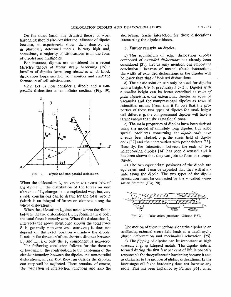
4.2.2. Let us now consider a dipole and a non- parallel dislocation in an infinite medium (Fig. 19).
FIG. 19. - Dipole and non-parallel dislocation.
When the dislocation L, moves in the stress field of the dipole D, the distribution of the forces on unit elements of L, changes in a complicated way, but very simple conclusions can be drawn for the total force F (which is an integral of forces on elements along the whole dislocation).
When the dislocation L, does not intersect the ribbon between the two dislocations L,, L, forming the dipole, the total force is exactly zero. When the dislocation L, intersects the above mentioned ribbon the total force F is generally non-zero and constant; it does not depend on the exact position cc inside the dipole. It acts in the direction of the shortest distance between L, and L,, i. e. only the Ey component is non-zero.
The following conclusion follows for the theories of hardening : the contribution to the hardening of the elastic interaction between the dipoles and non-parallel dislocations, in case that they run outside the dipoles, can very well be neglected. There remains, of course, the formation of intersection junctions and also the
short-range elastic interaction for those dislocations intersecting the dipole ribbons.
5. Further remarks on dipoles.
a) The equilibrium of edge dislocation dipoles composed of extended dislocations has already been considered [31]. Let us only mention one important conclusion : because of mutual elastic interaetion, the width of extended dislocations in the dipoles will be lower than that of isolated dislocations.
b) The elastic solution can only be used for dipoles with a height h b, practically h > 3 b. Dipoles with a smaller height can be better described as rows of point defects, i. e. the extensional dipoles as rows of vacancies and the compressional dipoles as rows of interstitial atoms. From this it follows that the pro- perties of these two types of dipoles for small height will differ, e. g. the compressional dipoles will have a larger energy than the extensional ones.
c) The main properties of dipoles have been derived using the model of infinitely long dipoles, but some special problems concerning the dipole ends have already been studied, e. g. the stress field of dipole ends [32] and their interaction with point defects [33]. Recently, the interaction between the ends of two neighbouring dipoles [34] has been discussed and it has been shown that they can join to form one longer dipole.
cl) The two equilibrium positions of the dipole are equivalent and it can be expected that they will alter- nate along the dipole. The two types of the dipole orientation must be connected by the so-called ovien- tation junction (Fig. 20).
FIG. 20. - Orientation junctions (Gilman [35]).
The motion of these junctions along the dipoles in an oscillating external stress field leads to a small cyclic plastic deformation and mechanical relaxation [25].
e) The flipping of dipoles can be important at high stresses, e. g. in fatigued metals. The dipoles debris, formed during the first few per cent of life, is probally responsible for the cyclic strain hardening because it acts as obstacles to the motion of gliding dislocations. In the later stages of life the hardening does not increase any more. This has been explained by Feltner 1361 : when
C 3 - 164 F. KROUPA
the crystal is filled up with debris, the motion of the gliding dislocations pratically stops and the cycles of plastic deformation are fundamentally perfomed by the flip-flop motion of the dislocation debris from stable equilibrium orientation to another without any further strain hardening.
f ) A possible influence of the dipoles on some mechanical properties of the crystals has already been mentioned (strain hardening, cyclic strain hardening, internal friction, creep, nucleation of cracks).
Gilman [l] proposed that also the changes of some other properties by plastic deformation can be, at least partly, explained by the influence of the dipoles.
Some of other mechanical properties can be explai- ned in this way : the decrease of the elastic moduli in cold-worked metals can be caused by polarization of the dipoles, and the Bauschinger effect by the line tension of the dipoles connected with the screw dislo- cations, which helps in their reverse motion. Also intrusions and extrusions on the surface of the fatigued specimens can be simply explained by the emergence of the extensional and compressional dipoles.
g) Most of the other physical properties, e. g. electrical, magnetic, and thermal, are influenced by plastic deformation and the idea to discuss this influen- ce in terms of dipoles seems to be very attractive. The main reason for this is that the earlier theoretical treatment in terms of individual dislocations was not very successful in some cases, especially in the problems of scattering of phonons and electrons by dislocations. The calculated values are often much lower than those obtained from experiments. This may be due to the fact that individual dislocations with the stress and strain fields proportional to I/r, i. e. with a slowly varying field, have only a small influence on the scattering. The main part of the scattering could be due to much more concentrated stress fields of dipoles that decrease as l/r2, and also to especially high dilatations in the dipoles centres.
6. Prismatic dislocation loops.
6.1. L o o p s WITHOUT EXTERNAL STRESS FIELD. - a) The stress field of dislocation loops is complicated and must be treated as a three-dimensional problem (in contrast to dipoles, the stress field of which can be mostly treated as a two-dimensional problem because of their predominant length). Nevertheless, the stress field and the energy of loops of different shapes have already been calculated by different authors (for references see [2]). Let us only mention that the long- range stress field (at distances much greater than the dimensions of the loop) decreases as l/r3, i. e. faster
than that of a dipole (l/r2), and much faster than that of a straight isolated dislocation (Ilr). The loop energy can be generally written in the form [37]
where p is the perimeter of the loop, and the constants C,, C, depend on the elastic constants and on the detailed shape of the loop. The energy per unit length of the loop is much lower than that of a straight dislocation (similarly as in the case of the dipoles). and the core energy will already become an important part of the total energy of the small loops.
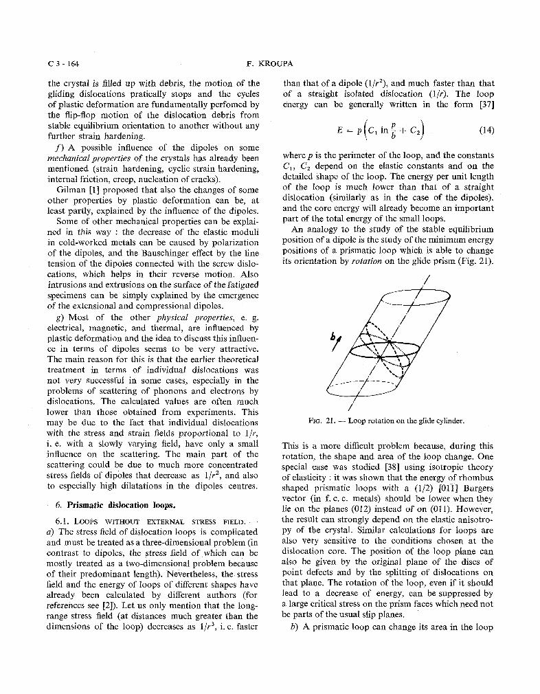
An analogy to the study of the stable equilibrium position of a dipole is the study of the minimum energy positions of a prismatic loop which is able to change its orientation by rotation on the glide prism (Fig. 21).
i FIG. 21. - Loop rotation on the glide cylinder.
This is a more difficult problem because, during this rotation, the shape and area of the loop change. One special case was studied [38] using isotropic theory of elasticity : it was shown that the energy of rhombus shaped prismatic loops with a (112) [Oli] Burgers vector (in f. c. c. metals) should be lower when they lie on the planes (012) instead of on (011). However, the result can strongly depend on the elastic anisotro- py of the crystal. Similar calculations for loops are also very sensitive to the conditions chosen at the dislocation core. The position of the loop plane can also be given by the original plane of the discs of point defects and by the splitting of dislocations on that plane. The rotation of the loop, even if it should lead to a decrease of energy, can be suppressed by a large critical stress on the prism faces which need not be parts of the usual slip planes.
b) A prismatic loop can change its area in the loop
DISLOCATION DIPOLES AND DISLOCATION LOOPS C 3 - 165
plane by climbing, the driving force for it being the dislocation line tension and the super- or undersa- turation of point defects. Under different conditions, the loops grow or disappear by climbing.
Let us only mention that the annealing-out of the loops [39] can be studied in a similar way as the annihilation of the dipoles. The main difference in the case of the loops formed after quenching follows from the fact that all the loops are made of vacancies. Shrinking of all the loops is not possible in the bulk material because it would lead to a high supersatura- tion of the vacancies. Thus, only the smaller loops will disappear during annealing while the larger loops will grow. In thin foils, however, all the loops will be annealed out because vacancies can migrate to the surface.
6.2 LOOPS IN A STRESS FIELD. - a) In an homogeneous stress field there are forces on elements of the disloca- tion line of a loop but the total force is zero (Fig. 22a).
d<, - C.., f. it. 0
a b
FIG. 22. - Forces on a loop in : U) homogeneous stress field, b) non-homogeneous stress field.
The components of the forces perpendicular to the loop plane tend to rotate the loop, i.e. there is the total moment of forces on the loop (this is an analogy to the polarization of a dipole) ; the components in the loop plane tend to expand or contract the loop and this effect can be called the induced surface tension in the loop.
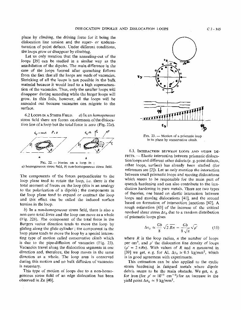
b) In a non-homogeneous stress field, there is also a non-zero total force and the loop can move as a whole (Fig. 226). The component of the total force in the Burgers vector direction tends to move the loop by gliding along the glide cylinder ; the component in the loop plane tends to move the loop by a special interes- ting type of motion called conservative climb which is due to the pipe-diffusion of vacancies (Fig. 23). Vacancies travel along the dislocation segments in one direction and, therefore, the loop moves in the same direction as a whole. The loop area is conserved during this motion and no bulk diffusion of vacancies is necessary.
This type of motion of loops due to a non-homo- geneous stress field of an edge dislocation has been observed in Zn [40].
FIG. 23. - Motion of a prismatic loop in its plane by conservative climb.
6.3. INTERACTION BETWEEN LOOPS AND OTHER DE-
FECTS. - Elastic interaction between prismatic disloca- tionloops and different other defects (e. g. point defects, other loops, surface) has already been studied (for references see [Z]). Let us only mention the interaction between small prismatic loops and moving dislocations which seems to be responsible for the main part of quench hardening and can also contribute to the irra- diation hardening in pure metals. There are two types of theories, one based on elastic interaction between loops and moving dislocations 1411, and the second based on formation of intersection junctions 1421. A rough estimation [43] of the increase of the critical resolved shear stress AT, due to a random distribution of prismatic loops gives
where R is the loop radius, n the number of loops per cm3, and p' the dislocation line density of loops (p' = 2 nRn). With values of R and n measured in [39] we get, e.g. for AI, AT, - 0.5 kg/mm2, which is in good agreement with experiments.
This estimation can be also applied to the cyclic strain hardening in fatigued metals where dipole debris seems to be the main obstacle. We get, e. g. for iron (for p' = 10'' cmw2) for an increase in the yield point Ao, -- 9 kglmm2.
C 3 - 166 F. KROUPA
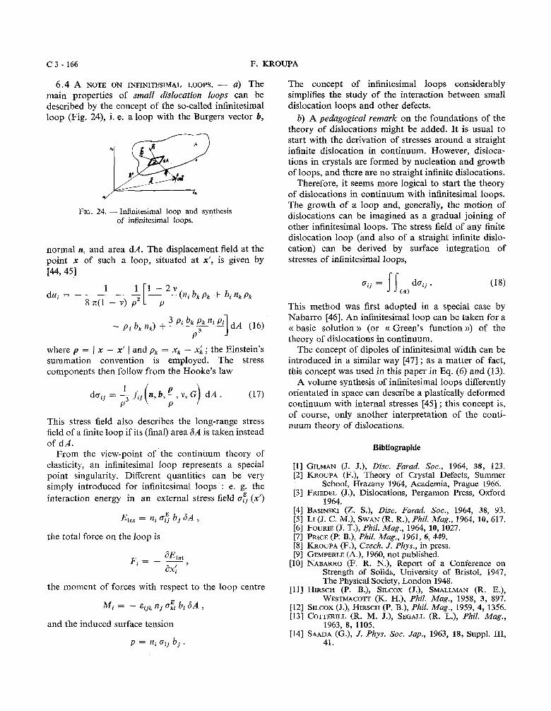
6.4 A NOTE ON INFINITESIMAL LOOPS. - a) The main properties of small dislocation loops can be described by the concept of the so-called infinitesimal loop (Fig. 24), i. e. a loop with the Burgers vector b,
FIG. 24. - Infinitesimal loop and synthesis of infinitesimal loops.
normal n, and area dA. The displacement field at the point x of such a loop, situated at X', is given by 144,451
where p = 1 x - X' 1 and p, = X, - xi ; the Einstein's summation convention is employed. The stress components then follow from the Hooke's law
This stress field also describes the long-range stress field of a finite loop if its (final) area 6 A is taken instead of dA.
From the view-point of the continuum theory of elasticity, an infinitesimal loop represents a special point singularity. Different quantities can be very simply introduced for infinitesimal loops : e. g. the interaction energy in an external stress field 0:. (X')
the total force on the loop is
the moment of forces with respect to the loop centre
and the induced surface tension
The concept of infinitesimal loops considerably simplifies the study of the interaction between small dislocation loops and other defects.
b) A pedagogical remark on the foundations of the theory of dislocations might be added. I t is usual to start with the derivation of stresses around a straight infinite dislocation in continuum. However, disloca- tions in crystals are formed by nucleation and growth of loops, and there are no straight infinite dislocations.
Therefore, it seems more logical to start the theory of dislocations in continuum with infinitesimal loops. The growth of a loop and, generally, the motion of dislocations can be imagined as a gradual joining of other infinitesimal loops. The stress field of any finite dislocation loop (and also of a straight infinite dislo- cation) can be derived by surface integration of stresses of infinitesimal loops,
This method was first adopted in a special case by Nabarro [46]. An infinitesimal loop can be taken for a ct basic solution )) (or c( Green's function B) of the theory of dislocations in continuum.
The concept of dipoles of infinitesimal width can be introduced in a similar way [47] ; as a matter of fact, this concept was used in this paper in Eq. (6) and (13).
A volume synthesis of infinitesimal loops differently orientated in space can describe a plastically deformed continuum with internal stresses [45] ; this concept is, of course, only another interpretation of the conti- nuum theory of dislocations.
[l] GILMAN (J. J.), Disc. Farad. Soc., 1964, 38, 123. [2] KROUPA (F.), Theory of Crystal Defects, Summer
School, Hrazany 1964, Academia, Prague 1966. [3j FRIEDEL (J.), Dislocations, Pergamon Press, Oxford
1964. [4] BASINSKI (Z. S.), Disc. Farad. Soc., 1964, 38, 93. [f] LI (J. C. M.), SWAN(R. R.), Phil. Mug., 1964, 10, 617. [6] FOURIE (J. T.), Phil. Mag., 1964, 10, 1027. [7] PRICE (P. B.), Phil. Mag., 1961, 6, 449. [8] KROUPA (F.), Czech. J. Phys., in press. [9] GEMPERLE (A.), 1960, not published.
[l01 NABARRO (F. R. N.), Report of a Conference on Strength of Solids, University of Bristol, 1947, The Physical Society, London 1948.
[l11 HIRSCH (P. B.), SILCOX (J.), SMALLMAN (R. E.), WESTMACOTT (K. H.), Phil. Mag., 1958, 3, 897.
[l21 SILCOX (J.), HIRSCH (P. B.), Phil. Mag., 1959, 4 , 1356. [l31 COTTERILL (R. M. J.), SEGALL (R. L.), Phil. Mug.,
1963, 8, 1105. [l41 SAADA (G.), J. Phys. Soc. Jap., 1963, 18, Suppl. 111,
41.
DISLOCATION DIPOLES AND DISLOCATION LOOPS C 3 - 167
[l51 SILCOX (J.), HIRSCH (P. B.), Phil. Mug., 1959, 4, 72. [l61 YOFFE (E. H.), Phil. Mag., 1960,5,161. [l71 THOMAS (G.), WHELAN (M. J.), Phil. Mug., 1959,4,511. [l81 KIRITANI (M.), SHIMOMURA (Y.), YOSHIDA (S.),
J. Phys. Soc. Jap., 1964,19,1624. [l91 JONES (D. A.), MITCHEL (J. W.), Phil. Mug., 1958,
3, 1. [20] BULLEN (F. P.), HENDERSON (F.), HUTCHINSON (M.M.),
WAIN (H. L.), Phil. Mag., 1964, 9,285. [21] LORETTO (M. H.), CLAREBROUGH (L. M.), SEGALL (R.
L.), Phil. Mug., 1965, 11, 111. [22] EYRE (B. L.), BARTLETT (A. F.), Phil. Mug., 1965,
12, 261. [23] WEERTMAN (J.), Phil. Mag., 1965, 11, 1217. [24] CHANG (R.), in The Physics and Chemistry of Cera-
mics, Editor S. Klingsberg, Gordon and Breach, New York, 1963, p. 275.
[25] NOVOTNP (J.), KROUPA (F.), Czech. J. Phys., in press. [26] COTTRELL (A. H.), BILBY (B. A.), Proc. Phys. Soc.,
1949, A 62, 49. [27] CHEN (H. S.), GILMAN (J. J.), HEAD (A. K.), J. Appl.
Phys., 1964, 35,2502. [28] GILMAN (J. J.), J. Appl. Phys., 1962, 33, 2703. [29] HIRSCH (P. B.), Disc. Farad. Soc., 1964, 38, 111. [30] KROUPA (F.), Actu Met., 1966, 14,60.
[31] CHEN (H. S.), GILMAN (J. J.), HEAD (A. K.), Phil. Mug., 1964, 10, 35.
[32] KROUPA (F.), Physica Status Solidi, 1965, 9, 27. [33] KROUPA (F.), NOVOTNP (J.), International Conference
on Electron Diffraction and Crystal Defects, Melbourne, 1965.
[34] FONTAINE (G.), JOUFFREY (B.), in press. [35] GILMAN (J. J.), J. Phys. Soc. Jap., 1963, 18, Suppl. I,
172. [36] FELTNER (C. E.), Phil. Mag., 1965,12,1229. [37] BACON (D. J.), CROCKER (A. G.), Phil. Mug., 1965,
12, 195. [38] BULLOUGH (R.), FOREMAN (A. J. E.), Phil. Mag.,
1964, 9, 315. [39] SILCOX (J.), WHELAN (M. J.), Phil. Mag., 1960, 5, 1. [40] KROUPA (F.), PRICE (P. B.), Phil. Mug., 1961, 6, 243. [41] KROUPA (F.), HIRSCH (P. B.), Disc. Farad. Soc., 1964,
38, 49. [42] SAADA (G.), WASHBURN (J.), J. Phys. Soc. Jap., 1963,
18, Suv~l . I. 43. 1431 KROUPA ?l?.), 'Freiberger Forschungshefte, 1965,
B 101, 181. [44] KROUPA (F.), Czech. J. Phys., 1963, A 13, 301. [45] KROUPA (F.), Gzech. J. Phys., 1964, B 12, 191. 1461 NABARRO (F. R. N.), Phil. Mug., 1951, 42, 1224. [47] KROWA (F.), Czech. J , Phys., 1965, B 15,896.


![Nucleation and propagation of dislocations near a ...engineering.snu.ac.kr/pdf/2001-2002(32)/2001_SCS... · prismatic dislocation loops [2-4), dislocation climb sources [5] and dislocation](https://img.dokumen.tips/doc/110x75/5f04810a7e708231d40e4c01/nucleation-and-propagation-of-dislocations-near-a-322001scs-prismatic.jpg)


![Journal of Crystal Growth - Uni Ulm...formation of closed dipoles close to the SiN x mask and therefore to a reduction of the dislocation density [16]. Such annihilation process was](https://img.dokumen.tips/doc/110x75/60e91add55efd5591740f9ea/journal-of-crystal-growth-uni-ulm-formation-of-closed-dipoles-close-to-the.jpg)


![Interatomic exchange coupling of BCC iron · temperature [2] [3] [4] and the resulting change of dominant orientation of dislocation loops from to at around](https://img.dokumen.tips/doc/110x75/606e04d808d1c01bcd3aeb05/interatomic-exchange-coupling-of-bcc-iron-temperature-2-3-4-and-the-resulting.jpg)