Embed Size (px)
Citation preview

DATE: October 21, 2011 PROJECT: Sprint PH80XC101 DC Ranch LOCATION: 10101 E Thompson Peak Pkwy
Scottsdale, AZ ISE JOB NO. 4491 DESIGN CRITERIA: DESIGN SATISFIES ALL CRITERIA FOR:
2006 IBC
ANSI/TIA/EIA-222-G W/ WIND – 95 MPH (3-SEC GUST), EXPOSURE C Kz = 1, TOPO CLASS 1, TOWER CLASS II
SEISMIC DATA: Ss=0.227 S1=0.070, SDS=0.242, SD1=0.112
Seismic Site Class D
Seismic Design Class B, Cs=0.154
WELDING PER AWS D1.1 LATEST EDITION MATERIALS: SOILS - EGS, Project # 1001.03, May 29, 2011 TAPERED SHAFT - ASTM A57 GR 65 (Fy=65 KSI) ANCHOR BOLTS - A615-75 (Fy=75 KSI) BASE PLATE STEEL - A572-60 (Fy=60 KSI) CONCRETE - F’c = 4000 PSI AT 28 Days REINFORCING STEEL - ASTM A615 BARS (Fy=60 KSI) DEFORMED
CONTENTS Pole Detail Foundation Detail Pole Geometry Calculations - Sheets 1 - 26
PREPARED BY: Glen L. Hunt III, PE
10/21/11


ISE Incorporated
Phone: FAX:
Job: Sprint PH80XC101 DC Ranch Project: ISE Job # 4491 Client: Larson Drawn by: Matt G App'd:
Code: TIA-222-G Date: 10/07/11 Scale: NTS Path:
C:\Documents and Settings\Cheetah One\Desktop\ISE Oct 1 to Oct 15 2000 Jobs\Larson\4491 Sprint PH80XC101 DC Ranch\RFQ Larson Quote # 2625 or #2644\4491 Sprint PH80XC101 DC Ranch.eri
Dwg No. E-1
70.0 ft
36.0 ft
1.0 ft
REACTIONS - 95 mph WINDTORQUE 9 kip-ft
17 KSHEAR 1021 kip-ft
MOMENT26 K
AXIAL
12
34.0
0035
.000
88
1.12
51.
125
17.2
0017
.200
17.2
0017
.200
A57
2-65
6.9
7.2
Sec
tion
Len
gth
(ft)
Num
ber o
f Sid
es
Thi
ckne
ss (i
n)
Top
Dia
(in)
Bot
Dia
(in)
Gra
de
Wei
ght (
K)
14.1
4' Lightning Rod 7016' Platform w/Mt Pipes 70(4) 9' x1' x 6" Panel 70(5) Sprint RRU 70(3) SPRINT Combiner 70Sprint Filter 70(4) 9' x1' x 6" Panel 70(5) Sprint RRU 70(3) SPRINT Combiner 70Sprint Filter 70(4) 9' x1' x 6" Panel 70(5) Sprint RRU 70(3) SPRINT Combiner 70Sprint Filter 70Musco Luminaire 64Musco Luminaire 64Musco Luminaire 64Musco Luminaire 64Musco Luminaire 64Musco Luminaire 64Musco Luminaire 61Musco Luminaire 61Musco Luminaire 61Musco Luminaire 61Musco Luminaire 61Musco Luminaire 61DESIGNED APPURTENANCE LOADINGTYPE TYPEELEVATION ELEVATION
4' Lightning Rod 7016' Platform w/Mt Pipes 70(4) 9' x1' x 6" Panel 70(5) Sprint RRU 70(3) SPRINT Combiner 70Sprint Filter 70(4) 9' x1' x 6" Panel 70(5) Sprint RRU 70(3) SPRINT Combiner 70Sprint Filter 70(4) 9' x1' x 6" Panel 70(5) Sprint RRU 70(3) SPRINT Combiner 70
Sprint Filter 70Musco Luminaire 64Musco Luminaire 64Musco Luminaire 64Musco Luminaire 64Musco Luminaire 64Musco Luminaire 64Musco Luminaire 61Musco Luminaire 61Musco Luminaire 61Musco Luminaire 61Musco Luminaire 61Musco Luminaire 61
MATERIAL STRENGTHGRADE GRADEFy FyFu Fu
A572-65 65 ksi 80 ksi
TOWER DESIGN NOTES1. Tower is located in Maricopa County, Arizona.2. Tower designed for Exposure C to the TIA-222-G Standard.3. Tower designed for a 95 mph basic wind in accordance with the TIA-222-G Standard.4. Deflections are based upon a 60 mph wind.5. TOWER RATING: 99.1%

RRIISSAATToowweerr Job
Sprint PH80XC101 DC Ranch
Page
1 of 8
ISE Incorporated
Project
ISE Job # 4491
Date
11:09:16 10/07/11
Phone: FAX:
Client
Larson Designed by
Matt G
Tower Input Data
There is a pole section.
This tower is designed using the TIA-222-G standard.
The following design criteria apply:
Tower is located in Maricopa County, Arizona.
Basic wind speed of 95 mph.
Structure Class II.
Exposure Category C.
Topographic Category 1.
Crest Height 0.000 ft.
Deflections calculated using a wind speed of 60 mph.
A non-linear (P-delta) analysis was used.
Pressures are calculated at each section.
Stress ratio used in pole design is 1.
Local bending stresses due to climbing loads, feedline supports, and appurtenance mounts are not considered.
Tapered Pole Section Geometry
Section Elevation
ft
Section
Length ft
Splice
Length ft
Number
of Sides
Top
Diameter in
Bottom
Diameter in
Wall
Thickness in
Bend
Radius in
Pole Grade
L1 70.000-36.000 34.000 0.000 8 17.200 17.200 1.125 4.500 A572-65
(65 ksi)
L2 36.000-1.000 35.000 8 17.200 17.200 1.125 4.500 A572-65
(65 ksi)
Tapered Pole Properties
Section Tip Dia.
in
Area
in2
I
in4
r
in
C
in
I/C
in3
J
in4
It/Q
in2
w
in
w/t
L1 18.617 60.040 2046.820 5.851 9.305 219.965 4192.619 29.263 2.463 2.19 18.617 60.040 2046.820 5.851 9.305 219.965 4192.619 29.263 2.463 2.19
L2 18.617 60.040 2046.820 5.851 9.305 219.965 4192.619 29.263 2.463 2.19
18.617 60.040 2046.820 5.851 9.305 219.965 4192.619 29.263 2.463 2.19
Monopole Base Plate Data
Base Plate Data Base plate is square Base plate is grouted
Anchor bolt grade A615-75
Anchor bolt size 2.250 in Number of bolts 12
Embedment length 72.000 in
f'c 4.000 ksi Grout space 3.000 in
Base plate grade A572-60
Base plate thickness 3.000 in Bolt circle diameter 26.750 in
Outer diameter 32.750 in
Inner diameter Socket Assembly Base plate type Plain Plate

RRIISSAATToowweerr Job
Sprint PH80XC101 DC Ranch
Page
2 of 8
ISE Incorporated
Project
ISE Job # 4491
Date
11:09:16 10/07/11
Phone: FAX:
Client
Larson Designed by
Matt G
Feed Line/Linear Appurtenances - Entered As Area
Description Face
or Leg
Allow
Shield
Component
Type
Placement
ft
Total
Number
CAAA
ft2/ft
Weight
klf
HJ5-50A (7/8 AIR) C No Inside Pole 70.000 - 1.000 20 No Ice 0.000 0.002
FSJ2-50 (3/8
SUPERFLEX. FOAM)
C No Inside Pole 70.000 - 1.000 6 No Ice 0.000 0.000
FSJ2-50 (3/8
SUPERFLEX. FOAM)
C No Inside Pole 65.000 - 1.000 2 No Ice 0.000 0.000
Feed Line/Linear Appurtenances Section Areas
Tower Section
Tower Elevation
ft
Face AR
ft2
AF
ft2
CAAA
In Face
ft2
CAAA
Out Face
ft2
Weight
K
L1 70.000-36.000 A
B C
D
0.000
0.000 0.000
0.000
0.000
0.000 0.000
0.000
0.000
0.000 0.000
0.000
0.000
0.000 0.000
0.000
0.000
0.000 1.068
0.000
L2 36.000-1.000 A B
C
D
0.000 0.000
0.000
0.000
0.000 0.000
0.000
0.000
0.000 0.000
0.000
0.000
0.000 0.000
0.000
0.000
0.000 0.000
1.100
0.000
Discrete Tower Loads
Description Face
or
Leg
Offset
Type
Offsets:
Horz
Lateral Vert
ft
ft ft
Azimuth
Adjustment
°
Placement
ft
CAAA
Front
ft2
CAAA
Side
ft2
Weight
K
4' Lightning Rod A None 0.000 70.000 No Ice 1.250 0.000 0.020
16' Platform w/Mt Pipes A None 0.000 70.000 No Ice 48.000 0.000 2.700
(4) 9' x1' x 6'' Panel A From Leg 4.500 0.000
0.000
0.000 70.000 No Ice 13.200 7.950 0.060
(5) Sprint RRU A From Leg 4.000 0.000
0.000
0.000 70.000 No Ice 3.033 1.633 0.060
(3) SPRINT Combiner A From Leg 4.000 0.000
0.000
0.000 70.000 No Ice 0.700 0.233 0.010
Sprint Filter A From Leg 1.000 0.000
0.000
0.000 70.000 No Ice 3.033 1.633 0.020
(4) 9' x1' x 6'' Panel B From Leg 4.500 0.000
0.000
0.000 70.000 No Ice 13.200 7.950 0.060
(5) Sprint RRU B From Leg 4.000 0.000
0.000
0.000 70.000 No Ice 3.033 1.633 0.060
(3) SPRINT Combiner B From Leg 4.000 0.000
0.000 70.000 No Ice 0.700 0.233 0.010

RRIISSAATToowweerr Job
Sprint PH80XC101 DC Ranch
Page
3 of 8
ISE Incorporated
Project
ISE Job # 4491
Date
11:09:16 10/07/11
Phone: FAX:
Client
Larson Designed by
Matt G
Description Face or
Leg
Offset Type
Offsets: Horz
Lateral
Vert ft
ft
ft
Azimuth Adjustment
°
Placement
ft
CAAA Front
ft2
CAAA Side
ft2
Weight
K
0.000
Sprint Filter B From Leg 1.000
0.000 0.000
0.000 70.000 No Ice 3.033 1.633 0.020
(4) 9' x1' x 6'' Panel C From Leg 4.500
0.000 0.000
0.000 70.000 No Ice 13.200 7.950 0.060
(5) Sprint RRU C From Leg 4.000
0.000 0.000
0.000 70.000 No Ice 3.033 1.633 0.060
(3) SPRINT Combiner C From Leg 4.000
0.000 0.000
0.000 70.000 No Ice 0.700 0.233 0.010
Sprint Filter C From Leg 1.000
0.000 0.000
0.000 70.000 No Ice 3.033 1.633 0.020
Dishes
Description Face
or Leg
Dish
Type
Offset
Type
Offsets:
Horz Lateral
Vert
ft
Azimuth
Adjustment
°
3 dB
Beam Width
°
Elevation
ft
Outside
Diameter
ft
Aperture
Area
ft2
Weight
K
Musco Luminaire A Paraboloid w/Radome
From Leg
1.000 4.500
0.000
Worst 64.000 2.000 No Ice 3.142 0.070
Musco Luminaire A Paraboloid w/Radome
From Leg
1.000 3.000
0.000
Worst 64.000 2.000 No Ice 3.142 0.070
Musco Luminaire A Paraboloid w/Radome
From Leg
1.000 1.500
0.000
Worst 64.000 2.000 No Ice 3.142 0.070
Musco Luminaire A Paraboloid w/Radome
From Leg
1.000 -1.500
0.000
Worst 64.000 2.000 No Ice 3.142 0.070
Musco Luminaire A Paraboloid
w/Radome
From
Leg
1.000
-3.000
0.000
Worst 64.000 2.000 No Ice 3.142 0.070
Musco Luminaire A Paraboloid w/Radome
From Leg
1.000 -4.500
0.000
Worst 64.000 2.000 No Ice 3.142 0.070
Musco Luminaire A Paraboloid w/Radome
From Leg
1.000 4.500
0.000
Worst 61.000 2.000 No Ice 3.142 0.070
Musco Luminaire A Paraboloid w/Radome
From Leg
1.000 3.000
0.000
Worst 61.000 2.000 No Ice 3.142 0.070
Musco Luminaire A Paraboloid w/Radome
From Leg
1.000 1.500
0.000
Worst 61.000 2.000 No Ice 3.142 0.070

RRIISSAATToowweerr Job
Sprint PH80XC101 DC Ranch
Page
4 of 8
ISE Incorporated
Project
ISE Job # 4491
Date
11:09:16 10/07/11
Phone: FAX:
Client
Larson Designed by
Matt G
Description Face or
Leg
Dish Type
Offset Type
Offsets: Horz
Lateral
Vert ft
Azimuth Adjustment
°
3 dB Beam
Width
°
Elevation
ft
Outside Diameter
ft
Aperture Area
ft2
Weight
K
Musco Luminaire A Paraboloid
w/Radome
From
Leg
1.000
-1.500 0.000
Worst 61.000 2.000 No Ice 3.142 0.070
Musco Luminaire A Paraboloid
w/Radome
From
Leg
1.000
-3.000 0.000
Worst 61.000 2.000 No Ice 3.142 0.070
Musco Luminaire A Paraboloid
w/Radome
From
Leg
1.000
-4.500 0.000
Worst 61.000 2.000 No Ice 3.142 0.070
Tower Forces - No Ice - Wind Normal To Face
Section
Elevation
ft
Add
Weight
K
Self
Weight
K
F
a
c e
e CF
qz
psf
DF
DR
AE
ft2
F
K
w
klf
Ctrl.
Face
L1
70.000-36.000
1.068 6.946 A
B
C D
1
1
1 1
1.2
1.2
1.2 1.2
24.25
1
1
1
1 1
1
1
1 1
52.749
52.749
52.749 52.749
1.689 0.050 D
L2
36.000-1.000
1.100 7.151 A
B C
D
1
1 1
1
1.2
1.2 1.2
1.2
19.89
2
1
1 1
1
1
1 1
1
54.300
54.300 54.300
54.300
1.426 0.041 D
Sum Weight: 2.169 14.097 OTM 114.019 kip-ft
3.114
Tower Forces - Service - Wind Normal To Face
Section Elevation
ft
Add Weight
K
Self Weight
K
F a
c
e
e CF
qz
psf
DF
DR
AE
ft2
F
K
w
klf
Ctrl. Face
L1 70.000-36.000
1.068 6.946 A B
C
D
1 1
1
1
1.2 1.2
1.2
1.2
8.655 1 1
1
1
1 1
1
1
52.749 52.749
52.749
52.749
0.603 0.018 D
L2
36.000-1.000
1.100 7.151 A
B C
D
1
1 1
1
1.2
1.2 1.2
1.2
7.099 1
1 1
1
1
1 1
1
54.300
54.300 54.300
54.300
0.509 0.015 D
Sum Weight: 2.169 14.097 OTM 40.694 kip-ft
1.112

RRIISSAATToowweerr Job
Sprint PH80XC101 DC Ranch
Page
5 of 8
ISE Incorporated
Project
ISE Job # 4491
Date
11:09:16 10/07/11
Phone: FAX:
Client
Larson Designed by
Matt G
Force Totals
Load
Case
Vertical
Forces
K
Sum of
Forces X
K
Sum of
Forces Z
K
Sum of
Overturning Moments, Mx
kip-ft
Sum of
Overturning Moments, Mz
kip-ft
Sum of Torques
kip-ft
Leg Weight 14.097
Bracing Weight 0.000 Total Member Self-Weight 14.097 -3.030 -0.991
Total Weight 21.596 -3.030 -0.991
Wind 0 deg - No Ice -0.437 -10.318 -607.350 29.130 3.126
Wind 90 deg - No Ice 10.318 0.437 27.091 -605.310 -5.313
Wind 180 deg - No Ice 0.437 10.318 601.290 -31.111 -3.126
Total Weight 21.596 -3.030 -0.991 Wind 0 deg - Service -0.156 -3.683 -218.714 9.760 1.116
Wind 90 deg - Service 3.683 0.156 7.720 -216.674 -1.896
Wind 180 deg - Service 0.156 3.683 212.654 -11.741 -1.116
Load Combinations
Comb.
No.
Description
1 Dead Only 2 1.2 Dead+1.6 Wind 0 deg - No Ice
3 0.9 Dead+1.6 Wind 0 deg - No Ice
4 1.2 Dead+1.6 Wind 90 deg - No Ice
5 0.9 Dead+1.6 Wind 90 deg - No Ice
6 1.2 Dead+1.6 Wind 180 deg - No Ice
7 0.9 Dead+1.6 Wind 180 deg - No Ice 8 Dead+Wind 0 deg - Service
9 Dead+Wind 90 deg - Service
10 Dead+Wind 180 deg - Service
Maximum Member Forces
Section
No.
Elevation
ft
Component
Type
Condition Gov.
Load
Comb.
Axial
K
Major Axis
Moment
kip-ft
Minor Axis
Moment
kip-ft
L1 70 - 36 Pole Max Tension 1 0.000 0.000 0.000 Max. Compression 6 -15.089 -26.268 -449.946
Max. Mx 4 -15.082 -454.965 -21.478
Max. My 2 -15.079 23.963 457.508
Max. Vy 4 15.210 -454.965 -21.478
Max. Vx 2 -15.213 23.963 457.508
Max. Torque 4 8.641 L2 36 - 1 Pole Max Tension 1 0.000 0.000 0.000
Max. Compression 6 -25.879 -52.015 -1012.463
Max. Mx 4 -25.879 -1017.632 -46.921 Max. My 2 -25.879 49.520 1020.244
Max. Vy 4 16.566 -988.737 -45.686
Max. Vx 2 -16.566 48.287 991.348 Max. Torque 4 8.625
RRIISSAATToowweerr Job
Sprint PH80XC101 DC Ranch
Page
6 of 8
ISE Incorporated
Project
ISE Job # 4491
Date
11:09:16 10/07/11
Phone: FAX:
Client
Larson Designed by
Matt G
Maximum Reactions
Location Condition Gov.
Load Comb.
Vertical
K
Horizontal, X
K
Horizontal, Z
K
Pole Max. Vert 6 25.915 -0.698 -16.509
Max. Hx 3 19.436 0.698 16.509
Max. Hz 3 19.436 0.698 16.509 Max. Mx 2 1020.244 0.698 16.509
Max. Mz 4 1017.632 -16.509 -0.698
Max. Torsion 4 8.590 -16.509 -0.698
Min. Vert 3 19.436 0.698 16.509
Min. Hx 5 19.436 -16.509 -0.698
Min. Hz 7 19.436 -0.698 -16.509 Min. Mx 6 -1012.463 -0.698 -16.509
Min. Mz 2 -49.523 0.698 16.509
Min. Torsion 2 -5.191 0.698 16.509
Tower Mast Reaction Summary
Load
Combination
Vertical
K
Shearx
K
Shearz
K
Overturning
Moment, Mx kip-ft
Overturning
Moment, Mz kip-ft
Torque
kip-ft
Dead Only 21.596 -0.000 0.001 -3.154 -1.031 0.001
1.2 Dead+1.6 Wind 0 deg - No
Ice
25.915 -0.698 -16.509 -1020.244 49.523 5.191
0.9 Dead+1.6 Wind 0 deg - No
Ice
19.436 -0.698 -16.509 -1005.948 49.159 5.131
1.2 Dead+1.6 Wind 90 deg - No Ice
25.915 16.509 0.698 46.927 -1017.632 -8.590
0.9 Dead+1.6 Wind 90 deg - No
Ice
19.436 16.509 0.698 47.248 -1004.025 -8.549
1.2 Dead+1.6 Wind 180 deg -
No Ice
25.915 0.698 16.509 1012.463 -52.012 -5.191
0.9 Dead+1.6 Wind 180 deg - No Ice
19.436 0.698 16.509 1000.222 -50.992 -5.131
Dead+Wind 0 deg - Service 21.596 -0.156 -3.682 -228.296 10.186 1.160
Dead+Wind 90 deg - Service 21.596 3.682 0.156 8.019 -226.128 -1.926 Dead+Wind 180 deg - Service 21.596 0.156 3.682 221.850 -12.293 -1.158
Maximum Tower Deflections - Service Wind
Section
No.
Elevation
ft
Horz.
Deflection
in
Gov.
Load
Comb.
Tilt
°
Twist
°
L1 70 - 36 10.170 8 1.040 0.015 L2 36 - 1 3.316 8 0.803 0.007
Critical Deflections and Radius of Curvature - Service Wind
Elevation
ft
Appurtenance Gov. Load
Comb.
Deflection
in
Tilt
°
Twist
°
Radius of Curvature
ft
70.000 4' Lightning Rod 8 10.170 1.040 0.023 17582
64.000 Musco Luminaire 8 8.807 0.989 0.021 14652 61.000 Musco Luminaire 8 8.135 0.963 0.019 9768

RRIISSAATToowweerr Job
Sprint PH80XC101 DC Ranch
Page
7 of 8
ISE Incorporated
Project
ISE Job # 4491
Date
11:09:16 10/07/11
Phone: FAX:
Client
Larson Designed by
Matt G
Maximum Tower Deflections - Design Wind
Section
No.
Elevation
ft
Horz.
Deflection in
Gov.
Load Comb.
Tilt
°
Twist
°
L1 70 - 36 45.205 2 4.606 0.065
L2 36 - 1 14.795 2 3.580 0.032
Critical Deflections and Radius of Curvature - Design Wind
Elevation
ft
Appurtenance Gov.
Load
Comb.
Deflection
in
Tilt
°
Twist
°
Radius of
Curvature
ft
70.000 4' Lightning Rod 2 45.205 4.606 0.102 4020
64.000 Musco Luminaire 2 39.163 4.495 0.093 3350
61.000 Musco Luminaire 2 36.183 4.436 0.089 2233
Base Plate Design Data
Plate Thickness
in
Number of Anchor
Bolts
Anchor Bolt Size
in
Actual
Allowable Ratio
Bolt
Tension K
Actual
Allowable Ratio
Bolt
Compression K
Actual
Allowable Ratio
Plate
Stress ksi
Actual
Allowable Ratio
Stiffener
Stress ksi
Controlling Condition
Ratio
3.000 12 2.250 173.576
223.654
0.78
177.889
371.266
0.48
53.112
54.000
0.98
Plate 0.98
Compression Checks
Pole Design Data
Section No.
Elevation
ft
Size
L
ft
Lu
ft
Kl/r
A
in2
Pu
K
Pn
K
Ratio
Pu
Pn
L1 70 - 36 (1) TP17.2x17.2x1.125 34.000 69.000 141.5 60.040 -15.079 677.369 0.022
L2 36 - 1 (2) TP17.2x17.2x1.125 35.000 69.000 141.5 60.040 -25.879 677.369 0.038

RRIISSAATToowweerr Job
Sprint PH80XC101 DC Ranch
Page
8 of 8
ISE Incorporated
Project
ISE Job # 4491
Date
11:09:16 10/07/11
Phone: FAX:
Client
Larson Designed by
Matt G
Pole Bending Design Data
Section
No.
Elevation
ft
Size
Mux
kip-ft
Mnx
kip-ft
Ratio
Mux
Mnx
Muy
kip-ft
Mny
kip-ft
Ratio
Muy
Mny
L1 70 - 36 (1) TP17.2x17.2x1.125 458.135 1072.333 0.427 0.000 1072.333 0.000
L2 36 - 1 (2) TP17.2x17.2x1.125 1021.442 1072.333 0.953 0.000 1072.333 0.000
Pole Shear Design Data
Section
No.
Elevation
ft
Size
Actual
Vu
K
Vn
K
Ratio
Vu
Vn
Actual
Tu
kip-ft
Tn
kip-ft
Ratio
Tu
Tn
L1 70 - 36 (1) TP17.2x17.2x1.125 15.231 1027.120 0.015 5.213 2542.958 0.002 L2 36 - 1 (2) TP17.2x17.2x1.125 16.579 1027.120 0.016 5.191 2542.958 0.002
Pole Interaction Design Data
Section
No.
Elevation
ft
Ratio
Pu
Pn
Ratio
Mux
Mnx
Ratio
Muy
Mny
Ratio
Vu
Vn
Ratio
Tu
Tn
Comb.
Stress Ratio
Allow.
Stress Ratio
Criteria
L1 70 - 36 (1) 0.022 0.427 0.000 0.015 0.002 0.450
1.000 4.10-1a
L2 36 - 1 (2) 0.038 0.953 0.000 0.016 0.002 0.991
1.000 4.10-1a
Section Capacity Table
Section
No.
Elevation
ft
Component
Type
Size Critical
Element
P
K
øPallow
K
%
Capacity
Pass
Fail
L1 70 - 36 Pole TP17.2x17.2x1.125 1 -15.079 677.369 45.0 Pass L2 36 - 1 Pole TP17.2x17.2x1.125 2 -25.879 677.369 99.1 Pass
Summary
Pole (L2) 99.1 Pass
Base Plate 98.4 Pass
RATING = 99.1 Pass

ISE Incorporated Job: Sprint PH80XC101 DC Ranch
3470 W. Jasper Drive Project: ISE Job No. 4491
Chandler, Arizona Clent: Larson
Phone: 602-403-8614 Date: October 21, 2011
FAX: 623-321-1283 Designed by: Glen Hunt
SEISMIC DATA
Conterminous 48 States
2005 ASCE 7 Standard
Latitude = 33.666444
Longitude = -111.865902
Spectral Response Accelerations Ss and S1
Ss and S1 = Mapped Spectral Acceleration Values
Site Class B - Fa = 1.0 ,Fv = 1.0
Data are based on a 0.05 deg grid spacing
Period Sa
(sec) (g)
0.2 0.227 (Ss, Site Class B)
1.0 0.070 (S1, Site Class B)
Conterminous 48 States
2005 ASCE 7 Standard
Latitude = 33.666444
Longitude = -111.865902
Spectral Response Accelerations SMs and SM1
SMs = Fa x Ss and SM1 = Fv x S1
Site Class D - Fa = 1.6 ,Fv = 2.4
Period Sa
(sec) (g)
0.2 0.364 (SMs, Site Class D)
1.0 0.168 (SM1, Site Class D)
Conterminous 48 States
2005 ASCE 7 Standard
Latitude = 33.666444
Longitude = -111.865902
Design Spectral Response Accelerations SDs and SD1
SDs = 2/3 x SMs and SD1 = 2/3 x SM1
Site Class D - Fa = 1.6 ,Fv = 2.4
Period Sa
(sec) (g)
0.2 0.242 (SDs, Site Class D)
1.0 0.112 (SD1, Site Class D)

ISE Incorporated Job: Sprint PH80XC101 DC Ranch
3470 W. Jasper Drive Project: ISE Job No. 4491
Chandler, Arizona Clent: Larson
Phone: 602-403-8614 Date: October 21, 2011
FAX: 623-321-1283 Designed by: Glen Hunt
SEISMIC CALCULATIONS
ASCE 7-05 Seismic Design Requirements for Non-Building Structures Not Similar to Buildings
IBC/CBC Section 1613 Earthquake Loads
REFERENCE
Importance Factor
I = 1 ASCE 7-05 Table 11.5-1
Site Classification
D IBC/CBC Table 1613.5.2/1613A.5.2
Site Coefficients
SS = 0.227 Mapped Spectral Accelerations: Short Period
S1 = 0.070 Mapped Sectral Accelerations: 1 sec Period
Fa = 1.600 Site Coefficient ASCE 7-05 Table 11.4-1;
IBC/CBC Table 1613.5.3(1)/1613A.5.3(1)
Fv = 2.400 Site Coefficient ASCE 7-05 Table 11.4-2;
IBC/CBC Table 1613.5.3(2)/1613A.5.3(2)
SMS = 0.363 Max Spectral Accelerations: Short Periods ASCE 7-05 Eqn. 11.4-1;
IBC/CBC Eqn. 16-37/16A-37
SM1 = 0.168 Max Spectral Accelerations: 1sec Period ASCE 7-05 Eqn. 11.4-2;
IBC/CBC Eqn. 16-38/16A-38
Design Spectral Response Acceleration Parameters ASCE 7-05 11.4.4; IBC/CBC 1613.5.4/1613A.5.4
SDS = 0.242 5% Damped Spectral Acceleration: Short Period ASCE 7-05 Eqn. 11.4-3;
IBC/CBC Eqn. 16-39/16A-39
SD1 = 0.112 5% Damped Spectral Acceleration: 1 sec Period ASCE 7-05 Eqn. 11.4-4;
IBC/CBC Eqn. 16-40/16A-40
SDC = B Seismic Design Category ASCE 7-05 Tables 11.6-1 & 11.6-2
IBC/CBC Table 1613.5.6(1) & 1613A.5.6(2)
if S1>0.75 then E
Equivalent Lateral Force Procedure
T = Ct hnx = 0.484 Fundamental Period ASCE 7-05 Eqn. 12.8-7
Ct = 0.020 Period Parameter ASCE 7-05 Table 12.8-2
x = 0.750 Period Parameter ASCE 7-05 Table 12.8-2
hn = 70.000 Structure Height (ft)
R = 1.500 Response Modification Factor ASCE 7-05 Table 15.4-2
TL = 8.000 Long-Period Transition Period ASCE 7-05 Figure 22-15
Cs =SDS/[R/I] = 0.161 Seismic Response Coefficient ASCE 7-05 Eqn. 12.8-2
where;
Cs > 0.030 Lower Limit ASCE 7-05 Eqn. 15.4-1
Cs >0.8 S1/[R/I] = 0.037 Lower Limit for S1 > 0.6g ASCE 7-05 Eqn. 15.4-2
Cs <SD1/T[R/I] = 0.154 Upper Limit for T < TL ASCE 7-05 Eqn. 12.8-3
Cs <SD1TL/T2[R/I] = 2.550 Upper Limit for T > TL ASCE 7-05 Eqn. 12.8-4
Design Value Cs = 0.154
W = 21.596 Pole Dead Weight + Appurtenances Weight (kips)
V = CsW = 3.332 Equivalent Seismic Base Shear (kips) ASCE 7-05 Eqn. 12.8-1
Fwind = 16.525 Wind Base Shear (kips) : 1.6W
Lateral Wind Shear > Seismic Base Shear : Wind Controls Design

10/1
2/20
11
Va
ria
ble
Des
cri
pti
on
Va
lue
Un
itP
roje
ct:
DC
Ran
chL
oc
ati
on
:S
cotts
dale
, AZ
Di
Flan
ge In
side
Dia
met
er18
.620
inD
es
cri
pti
on
:
Do
Flan
ge O
utsi
de D
iam
eter
25.7
50in
Dbc
Flan
ge B
olt C
ircle
Dia
met
er22
.750
int
Thic
knes
s of
Fla
nge
2.75
0in
twFi
llet W
eld
Siz
e0.
75in
N
N
umbe
r of B
olts
(Mus
t be
mul
tiple
of 4
)16
dN
omin
al B
olt D
iam
eter
1.25
0in
FpP
re-L
oad
on B
olt a
s %
of A
llow
able
Bol
t Ten
sion
90%
TTo
rque
to p
rodu
ce b
olt p
rete
nsio
n1,
056
lb
-ft
M
M
omen
t on
Flan
ge45
8,13
5
lb
-ftM
tTo
rque
on
Pip
e-
lb
-ftV
Ver
tical
Loa
d (+
is T
ensi
le)
(15,
079)
lbS
She
ar L
oad
on F
lang
e15
,231
lb
Fyb
Allo
wab
le F
lang
e Yi
eld
Stre
ss50
,000
lb
/in^2
Fbg
Allo
wab
le G
usse
t Yie
ld S
tress
50,0
00
lb/in
^2E
Mod
ulus
of E
last
icity
for F
lang
e30
,000
,000
lb/in
^2E
bM
odul
us o
f Ela
stic
ity fo
r Bol
t30
,000
,000
lb/in
^2Ft
A
llow
able
Bol
t Ten
sion
54,0
00
lb/in
^2N
otes
:Fv
A
llow
able
Bol
t She
ar11
,880
lb
/in^2
*
De
sig
n c
on
sid
ers
exte
rna
l str
uctu
ral lo
ad
ing
s o
nly
.
FwYi
eld
Stre
ss o
f Wel
dE
lect
rode
:E
70xx
57,0
00
lb/in
^2
* G
aske
t se
atin
g a
nd
pre
ssu
re a
re n
ot
co
nsid
ere
d.
*
No
t to
be
use
d f
or
pre
ssu
re c
on
tain
ing
fla
ng
es.
Su
mm
ary
of
Co
nd
itio
ns
Ch
ec
ke
dU
nit
y R
ati
oR
es
ult
Bol
t Ten
sion
(Act
ual T
ensi
on/A
llow
able
Ten
sion
)0.
90O
KB
olt S
hear
(Act
ual S
hear
/Allo
wab
le S
hear
)0.
07O
KFl
ange
Stre
ss (R
equi
red
Thic
knes
s/A
ctua
l Thi
ckne
ss)
0.92
OK
Wel
d S
tress
(Act
ual F
illet
Siz
e/R
equi
red
Fille
t Siz
e)0.
84O
K
STR
UC
TUR
AL
FLA
NG
E D
ES
IGN
Fla
ng
e D
ime
nsio
ns
Bo
ltin
g I
nfo
rma
tio
n
Lo
ad
s
Flan
ge S
plic
e
Ma
teri
al P
rop
ert
ies
tw
T
OD
BC
D
ID
Cop
yrig
ht 2
001
- Mec
a En
terp
rises
, Inc
.w
ww
.mec
acon
sulti
ng.c
omPa
ge 1
of 3

10/1
2/20
11S
TRU
CTU
RA
L FL
AN
GE
DE
SIG
N
Ab
N
omin
al B
olt A
rea
Nom
inal
Are
a of
Bol
t1.
23in
^2P
Bol
t Loa
d du
e to
V a
nd M
4*M
/(N*D
i)+V
/N72
,871
lbkm
Stif
fnes
s of
Mat
eria
lP
I()*E
*d/(2
*LN
(5*(
2*t+
0.5*
d)/(2
*t+2
.5*d
)))
46,4
86,0
38
lb
/in^2
kbS
tiffn
ess
of B
olt
PI()
*d^2
*Eb/
(4*(
2*t))
6,69
3,73
4
lb
/in^2
CC
Rat
io o
f Bol
t Stif
fnes
s to
Tot
al S
tiffn
ess
Kb/
(Kb+
Km
)0.
126
FiB
olt I
nitia
l Loa
d (P
reLo
ad)
Ft*0
.85*
Fp*A
b50
,695
lbFm
inM
in F
orce
to k
eep
flg in
com
pres
sion
1.1*
(P+Q
)*(1
-CC
)70
,069
lbFb
Act
ual T
ensi
le L
oad
on B
olt
Kb*
(P+Q
)/(K
b+K
m)+
Fi59
,867
lbFb
allo
wA
llow
able
Bol
t Ten
sile
Loa
d - P
ure
Tens
ion
Ft*A
b66
,268
lbFb
com
bA
llow
able
Bol
t Ten
sile
Loa
d - T
ens
& S
hear
((54
^2-3
.75*
(S/A
b)^2
)^0.
5)*A
b66
,242
lb
SS
hear
on
Bol
tS
/N+2
*Mt/(
Dbc
*N)
952
lbS
allo
wA
llow
able
She
ar o
n B
olt
Fv*A
b14
,579
lb
IwB
endi
ng M
omen
t of I
nter
tia fo
r Wel
d2*
Pi()
*(D
i/2)^
3*0.
707*
tw2,
688
in
^3Jw
Pol
ar M
omen
t of I
nerti
a fo
r Wel
d2*
Pi()
*(D
i/2)^
3*2*
0.70
7*tw
5,37
7
in^3
Aw
Are
a of
Wel
d2*
1.41
4*P
i()*t
w*D
i12
4.07
in^2
fbW
eld
Stre
ss d
ue to
Axi
al &
Ben
ding
abs(
M*(
Di/2
)/Iw
)+ab
s(V
/a)
19,1
59
lb
/in^2
Sw
Allo
wab
le W
eld
Stre
ss0.
4*Fw
22,8
00
lb
/in^2
ft
Wel
d S
tress
du
to T
orqu
eab
s(M
t/Jw
)-
lb/in
^2
Calc
ula
te B
olt
Lo
ad
ing
(Ref.
"M
ech
an
ica
l E
ng
ine
eri
ng
De
sig
n"
4th
ed
., S
hig
ley &
Mitch
ell)
The
shea
r bol
t loa
d is
acc
epta
ble
Ch
ec
k W
eld
ing
Wel
d S
tress
due
to A
xial
and
Ben
ding
Loa
d A
ccep
tabl
e
Wel
d S
tress
due
to T
orqu
e is
Acc
epta
ble
Cop
yrig
ht 2
001
- Mec
a En
terp
rises
, Inc
.w
ww
.mec
acon
sulti
ng.c
omPa
ge 2
of 3

10/1
2/20
11S
TRU
CTU
RA
L FL
AN
GE
DE
SIG
N
LnN
et F
lg a
rea
at e
ach
bolt
PI()
*Dbc
/N-(
d+0.
125)
3.09
in^2
LgG
ross
Flg
are
a fo
r eac
h bo
ltPI
()*D
bc/N
4.47
in^2
Del
taLn
/Lg
0.69
a'D
ist f
rom
Flg
OD
to B
olt H
ole
Edge
(Do-
Dbc
)*0.
5+d/
22.
13in
bD
ist f
rom
Bol
t CL
to P
ipe
OD
(Dbc
-Di)*
0.5
2.07
ina
Dis
t fro
m B
olt C
L to
Fla
nge
OD
1.25
*b2.
58in
b'D
ist f
rom
Pip
e O
D to
edg
e of
Bol
t Hol
eb-
d/2
1.44
inR
hoC
alcu
late
d Pa
ram
eter
bp/a
p0.
68Be
taC
alcu
late
d Pa
ram
eter
(1/R
ho)*
(C14
*C16
/P-1
)-0
.13
Alph
a'Al
pha
whe
re tr
eq'd
is m
inim
umM
inim
um o
f 1 o
r (1/
Del
ta)*
(Bet
a/(1
-Bet
a))
-0.1
7tc
Req
'd th
ick
to d
evel
op lo
ad w
/ no
pryi
ng((
8*P*
bp)/(
Lg*C
12))
^0.5
1.94
inAl
pha
Rat
io m
om@
BL
to M
om @
ste
m li
ne(1
/Del
ta)*
((P/
(Ft*A
b))/(
t/tc)
^2-1
)-0
.66
QPr
ying
For
ce p
er b
olt
Ft*A
b*D
elta
*Alp
ha*R
ho*(
t/tc)
^2-
lb
treq'
dR
equi
red
Flan
ge T
hick
ness
((8*
P*bp
)/(Lg
*Fyb
*0.6
6*(1
+Del
ta*A
lpha
')))^
0.5
2.54
in
Desig
n T
hic
kn
ess o
f F
lan
ge f
or
Bo
lt L
oad
(w
ith
ou
t G
ussets
):
(Ref. "
Manual of S
teel C
onstr
uction A
SD
" 9th
ed., P
age 4
-89)
Rat
io o
f net
are
a (@
bol
t lin
e) &
gro
ss
area
Cop
yrig
ht 2
001
- Mec
a En
terp
rises
, Inc
.w
ww
.mec
acon
sulti
ng.c
omPa
ge 3
of 3


ISE Incorporated Job: Sprint PH80XC101 DC Ranch
3470 W. Jasper Drive Project: ISE Job No. 4491
Chandler, Arizona Clent: Larson
Phone: 602-403-8614 Date: October 21, 2011
FAX: 623-321-1283 Designed by: Glen Hunt
ANCHOR BOLT & BASE PLATE DESIGN
Calculated Wind Force Reactions from Force Totals Table: M = 608.048 k-Ft, V = 10.327 kip, A = 21.6 kip
(Round or Square Plate)
Geometry
Plate Square/Round Plate = Round
Plate Width/Diameter: OD = 32.75 inch
Pole Diameter: Dp = 17.2 inch
Bolt Circle Diameter: BC = 26.75 inch
No. Bolts: N = 12
Bolt Moment of Inertia: I = 1073.344 inch2
(1/8)(N BC2 )
Anchor Bolt Diameter: Dbolt = 2.25 inch
Nominal Anchor Bolt Area: An = 3.98 inch2
Materials
Anchor Bolt Material: Fu = 100 KSI A615 GR 75
Base Plate Material: Fy = 60 KSI A572 GR60
Loads
Unfactored Base Reactions
M = 608.048
V = 10.327
A = 21.596
Factored Moment: Mu = 1216.096 Kip-Ft 2 X Base Reaction
Factored Base Shear: V = 20.654 Kips 2 X Base Reaction
Axial Dead Load: A = 25.9152 Kips 1.2 DL
Analysis
ANCHOR BOLTS
Anchor Bolt Tension: T = Pu = 179.6865 Kips [(Mu BC/2) / I] - A/N
Anchor Bolt Compression: C = 184.0057 Kips [(Mu BC/2) / I] + A/N
Anchor Bolt Shear: Vu = 1.721167 Kips/bolt V / N
AB Design Strength - Rnt = FuAn = 298.2059 Kips = 0.75 for Rupture Strength
INTERACTION PER TIA-222-G Section 4.9.9
[Pu + Vu/ ] / Rnt < 1.0 For Detail Type D
Ratio = 0.62 < 1.0 OK!!
UN-GROUTED BASEPLATE
Plate Bending: Mpb = 878.63 Kip-Inch Mpb =C(1/2)(BC-Dp)
Required Plastic Modulus: Z = 16.27 inch3
Z = Mpb / (0.9)Fy
Square Plate Bend Line Length: L = 29.12 inch L =[21/2
(OD) - Dp]
Round Plate Bend Line Length: L = 7.78 inch L = .75BC SIN(360/N)
Required Plate Thickness: Tpl = 2.89 inch Tpl = [4Z/ L]1/2
Design Summary
(12) 2.25 Diameter A615 GR 75 Bolts on 26.75" BC Diameter
3" X 32.75" Round A572 GR60 Base Plate

ISE Incorporated Job: Sprint PH80XC101 DC Ranch
3470 W. Jasper Drive Project: ISE Job No. 4491
Chandler, Arizona Clent: Larson
Phone: 602-403-8614 Date: October 21, 2011
FAX: 623-321-1283 Designed by: Glen Hunt
Pole to Base Weld Connection
Socket Flange Assembly
Dp = 17.2 inch
Factored Moment: Mu = 1021.445 Kip-Ft Factored Moment
Factored Base Shear: V = 16.525 Kips Factored Shear
Weld Thickness: Tw = 1.6875 inch Filet Weld Thickness (Top Weld + 1/2 Bottom Weld)
Weld Material Yield: Fyw = 70 ksi
Allowable Weld Force: Fallow = 40.087 kip/inch Fallow = (.707)Tw (.48)Fyw
Weld Force: Fw = 23.446 kip/inch Fw = (3/4)Sqrt [ {Mu/Tw (Dp2/4)}
2 + {V/Tw Dp}
2 ]
Base Weld Stress Ratio = 58.489 %
DESIGN: APPLY 1 1/8" FILET WELD TO POLE AT TOP & BOTTOM OF PLATE

ISE Incorporated Job: Sprint PH80XC101 DC Ranch
3470 W. Jasper Drive Project: ISE Job No. 4491
Chandler, Arizona Clent: Larson
Phone: 602-403-8614 Date: October 21, 2011
FAX: 623-321-1283 Designed by: Glen Hunt
Anchor Bolt Development (ACI 318-05)
Anchor bolts are mechanically anchored with nuts and load plates at bottom of bolts.
Failure cones emanate at 35 degrees from top of nut.
The failure cones from the 4 bolts overlap and exit the sides of the caisson.
Concrete is assumed to crack and carry no load so, vertical reinforcing steel must be developed to transfer bolt loads.
Calculations presented below determine the required length of anchor bolt embedment
and reinforcing development necessary to transfer the design loads.
Minimum Development Length per ACI 318-05 12.2.2, Eq 12-1.
ld = db[fy/√(fc)](3/40)(φtφeλ/2.5) :
where; fy = 60,000psi, f’c = 4000 psi, and φtφeλ = 1.0,
ld = 28.46 db For # 10 Bar ld = 35.58 in.
Anchor Bolts are 2-1/4" X 84" with 72" Embedment on 26.75" Bolt Circle
Reinforcing Cage Diameter = 42.00 in.
Minimum Required AB Depth
cover = 3.00 in.
bottom grip = 3.00 in.
½(Cage-BC) = 7.63 in.
lmin = ld + cover + bottom grip + ½(Cage-BC)/tan65 = 45.13 in.
Bolt Embedment Provided = 72.00 in.
Anchor bolts are restrained by fully developed reinforcement satisfying the requirements of 318-05 Appendix D.

ISE Incorporated Job: Sprint PH80XC101 DC Ranch
3470 W. Jasper Drive Project: ISE Job No. 4491
Chandler, Arizona Clent: Larson
Phone: 602-403-8614 Date: October 21, 2011
FAX: 623-321-1283 Designed by: Glen Hunt
Foundation Design -
Calculated Wind Force Reactions from Force Totals Table: M = 608.048 k-Ft, V = 10.327 kip, A = 21.6 kip
Soils Report – EGS, Project # 1001.03, May 29, 2011
A 48” diameter x 22’-0” pier with 6” exposure is required.
LPile solutions and data are attached.
Per LPile Solutions:
w/ (12) #10 Vertical Reinforcing bars-
Un-factored Pier Moment Capacity @ 0.003in/in Strain = 17609.291 In-Kip = 1467 Ft-Kip
Maximum Pier Moment Load Case 2 (ACI 1.2DL + 1.6 WL)
M = 13369.96 In-Kip = 1114-Kip
Pier Head Deflection for Load Case 1 (Un-Factored Calculated Wind Force) = 0.537”
Plots of deflection, Bending Moment and Shear follow the LPile results printout.
The following Load Cases are plotted:
Load Case 1 - Un-Factored Calculated Wind Force Reactions
Load Case 2 - ACI Factored Wind Force Reactions 1.2DL + 1.6 WL

4491 DC Ranch Fndn.lpo==============================================================================
LPILE Plus for Windows, Version 5.0 (5.0.39)
Analysis of Individual Piles and Drilled Shafts Subjected to Lateral Loading Using the p-y Method
(c) 1985-2007 by Ensoft, Inc. All Rights Reserved
==============================================================================
This program is licensed to:
Glen Hunt PEISE, Inc
Path to file locations: C:\Documents and Settings\Glen Hunt PE\Desktop\4491 DC Ranch\Name of input data file: 4491 DC Ranch Fndn.lpdName of output file: 4491 DC Ranch Fndn.lpoName of plot output file: 4491 DC Ranch Fndn.lppName of runtime file: 4491 DC Ranch Fndn.lpr
------------------------------------------------------------------------------ Time and Date of Analysis------------------------------------------------------------------------------
Date: October 11, 2011 Time: 16:01:26
------------------------------------------------------------------------------ Problem Title------------------------------------------------------------------------------
DC Ranch
------------------------------------------------------------------------------ Program Options------------------------------------------------------------------------------
Units Used in Computations - US Customary Units: Inches, Pounds
Basic Program Options:
Analysis Type 3: - Computation of Nonlinear Bending Stiffness and Ultimate Bending Moment Capacity with Pile Response Computed Using Nonlinear EI
Computation Options:- Only internally-generated p-y curves used in analysis- Analysis does not use p-y multipliers (individual pile or shaft action only)- Analysis assumes no shear resistance at pile tip- Analysis for fixed-length pile or shaft only- No computation of foundation stiffness matrix elements- Output pile response for full length of pile- Analysis assumes no soil movements acting on pile- No additional p-y curves to be computed at user-specified depths
Solution Control Parameters:Page 1

4491 DC Ranch Fndn.lpo- Number of pile increments = 100- Maximum number of iterations allowed = 300- Deflection tolerance for convergence = 5.0000E-05 in- Maximum allowable deflection = 1.0000E+02 in
Printing Options:- Values of pile-head deflection, bending moment, shear force, and soil reaction are printed for full length of pile.- Printing Increment (spacing of output points) = 1
------------------------------------------------------------------------------ Pile Structural Properties and Geometry------------------------------------------------------------------------------
Pile Length = 270.00 in
Depth of ground surface below top of pile = 42.00 in
Slope angle of ground surface = .00 deg.
Structural properties of pile defined using 2 points
Point Depth Pile Moment of Pile Modulus of X Diameter Inertia Area Elasticity in in in**4 Sq.in lbs/Sq.in----- --------- ----------- ---------- ---------- ----------- 1 0.0000 48.00000000 260576.0000 1810.0000 3605.00000 2 300.0000 48.00000000 260576.0000 1810.0000 3605.00000
Please note that because this analysis makes computations of ultimatemoment capacity and pile response using nonlinear bending stiffness that the above values of moment of inertia and modulus of are not usedfor any computations other than total stress due to combined axial loading and bending.
------------------------------------------------------------------------------ Soil and Rock Layering Information------------------------------------------------------------------------------
The soil profile is modelled using 1 layers
Layer 1 is sand, p-y criteria by Reese et al., 1974Distance from top of pile to top of layer = 42.000 inDistance from top of pile to bottom of layer = 300.000 inp-y subgrade modulus k for top of soil layer = 90.000 lbs/in**3p-y subgrade modulus k for bottom of layer = 90.000 lbs/in**3
(Depth of lowest layer extends 30.00 in below pile tip)
------------------------------------------------------------------------------ Effective Unit Weight of Soil vs. Depth------------------------------------------------------------------------------
Effective unit weight of soil with depth defined using 2 points
Point Depth X Eff. Unit Weight No. in lbs/in**3----- ---------- ---------------- 1 42.00 .07270
Page 2

4491 DC Ranch Fndn.lpo 2 300.00 .07270
------------------------------------------------------------------------------ Shear Strength of Soils------------------------------------------------------------------------------
Shear strength parameters with depth defined using 2 points
Point Depth X Cohesion c Angle of Friction E50 or RQD No. in lbs/in**2 Deg. k_rm %----- -------- ---------- ------------------ ------ ------ 1 42.000 .00000 33.00 ------ ------ 2 300.000 .00000 33.00 ------ ------
Notes:
(1) Cohesion = uniaxial compressive strength for rock materials.(2) Values of E50 are reported for clay strata. (3) Default values will be generated for E50 when input values are 0.(4) RQD and k_rm are reported only for weak rock strata.
------------------------------------------------------------------------------ Loading Type------------------------------------------------------------------------------
Static loading criteria was used for computation of p-y curves.
------------------------------------------------------------------------------ Pile-head Loading and Pile-head Fixity Conditions------------------------------------------------------------------------------
Number of loads specified = 2
Load Case Number 1
Pile-head boundary conditions are Shear and Moment (BC Type 1)Shear force at pile head = 10.327 lbsBending moment at pile head = 7296576.000 in-lbsAxial load at pile head = 21596.000 lbs
Non-zero moment at pile head for this load case indicates the pile-head may rotate under the applied pile-head loading, but is not a free-head(zero moment) condition.
Load Case Number 2
Pile-head boundary conditions are Shear and Moment (BC Type 1)Shear force at pile head = 16524.000 lbsBending moment at pile head = 12257340.000 in-lbsAxial load at pile head = 25915.000 lbs
Non-zero moment at pile head for this load case indicates the pile-head may rotate under the applied pile-head loading, but is not a free-head(zero moment) condition.
Page 3
4491 DC Ranch Fndn.lpo
------------------------------------------------------------------------------ Computations of Nominal Moment Capacity and Nonlinear Bending Stiffness------------------------------------------------------------------------------
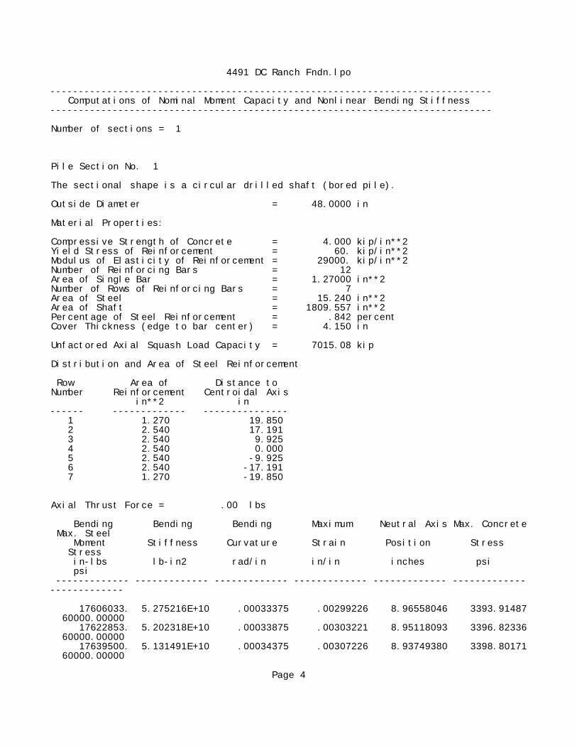
Number of sections = 1
Pile Section No. 1
The sectional shape is a circular drilled shaft (bored pile).
Outside Diameter = 48.0000 in
Material Properties:
Compressive Strength of Concrete = 4.000 kip/in**2Yield Stress of Reinforcement = 60. kip/in**2Modulus of Elasticity of Reinforcement = 29000. kip/in**2Number of Reinforcing Bars = 12Area of Single Bar = 1.27000 in**2Number of Rows of Reinforcing Bars = 7Area of Steel = 15.240 in**2Area of Shaft = 1809.557 in**2Percentage of Steel Reinforcement = .842 percentCover Thickness (edge to bar center) = 4.150 in
Unfactored Axial Squash Load Capacity = 7015.08 kip
Distribution and Area of Steel Reinforcement
Row Area of Distance to Number Reinforcement Centroidal Axis in**2 in------ ------------- --------------- 1 1.270 19.850 2 2.540 17.191 3 2.540 9.925 4 2.540 0.000 5 2.540 -9.925 6 2.540 -17.191 7 1.270 -19.850
Axial Thrust Force = .00 lbs
Bending Bending Bending Maximum Neutral Axis Max. Concrete Max. Steel Moment Stiffness Curvature Strain Position Stress Stress in-lbs lb-in2 rad/in in/in inches psi psi ------------- ------------- ------------- ------------- ------------- -------------------------- 17606033. 5.275216E+10 .00033375 .00299226 8.96558046 3393.91487 60000.00000 17622853. 5.202318E+10 .00033875 .00303221 8.95118093 3396.82336 60000.00000 17639500. 5.131491E+10 .00034375 .00307226 8.93749380 3398.80171 60000.00000
Page 4

4491 DC Ranch Fndn.lpo
Unfactored (Nominal) Moment Capacity at Concrete Strain of 0.003 = 17609.29091 in-kip
------------------------------------------------------------------------------ Computed Values of Load Distribution and Deflection for Lateral Loading for Load Case Number 1------------------------------------------------------------------------------
Pile-head boundary conditions are Shear and Moment (BC Type 1)Specified shear force at pile head = 10.327 lbsSpecified moment at pile head = 7296576.000 in-lbsSpecified axial load at pile head = 21596.000 lbs
Output Verification:
Computed forces and moments are within specified convergence limits.
Output Summary for Load Case No. 1:
Pile-head deflection = .53704038 inComputed slope at pile head = -.00612046Maximum bending moment = 7302103. lbs-inMaximum shear force = -53287.30322 lbsDepth of maximum bending moment = 45.90000000 inDepth of maximum shear force = 183.60000 inNumber of iterations = 54Number of zero deflection points = 1
------------------------------------------------------------------------------ Computed Values of Load Distribution and Deflection for Lateral Loading for Load Case Number 2------------------------------------------------------------------------------
Pile-head boundary conditions are Shear and Moment (BC Type 1)Specified shear force at pile head = 16524.000 lbsSpecified moment at pile head = 12257340.000 in-lbsSpecified axial load at pile head = 25915.000 lbs
Output Verification:
Computed forces and moments are within specified convergence limits.
Output Summary for Load Case No. 2:
Pile-head deflection = 1.40021378 inComputed slope at pile head = -.01375164Maximum bending moment = 13369963. lbs-inMaximum shear force = -112675.99000 lbsDepth of maximum bending moment = 78.30000000 inDepth of maximum shear force = 183.60000 in
Page 5

4491 DC Ranch Fndn.lpoNumber of iterations = 28Number of zero deflection points = 1
------------------------------------------------------------------------------ Summary of Pile Response(s)------------------------------------------------------------------------------
Definition of Symbols for Pile-Head Loading Conditions:
Type 1 = Shear and Moment, y = pile-head displacment inType 2 = Shear and Slope, M = Pile-head Moment lbs-inType 3 = Shear and Rot. Stiffness, V = Pile-head Shear Force lbsType 4 = Deflection and Moment, S = Pile-head Slope, radiansType 5 = Deflection and Slope, R = Rot. Stiffness of Pile-head in-lbs/rad
Load Pile-Head Pile-Head Axial Pile-Head Maximum Maximum Type Condition Condition Load Deflection Moment Shear 1 2 lbs in in-lbs lbs---- ------------ ------------ ----------- ----------- ----------- ----------- 1 V= 10.327 M= 7.30E+06 21596.0000 .5370404 7302103. -53287.3032 1 V= 16524. M= 1.23E+07 25915.0000 1.4002 1.3370E+07 -112676.
The analysis ended normally.
Page 6
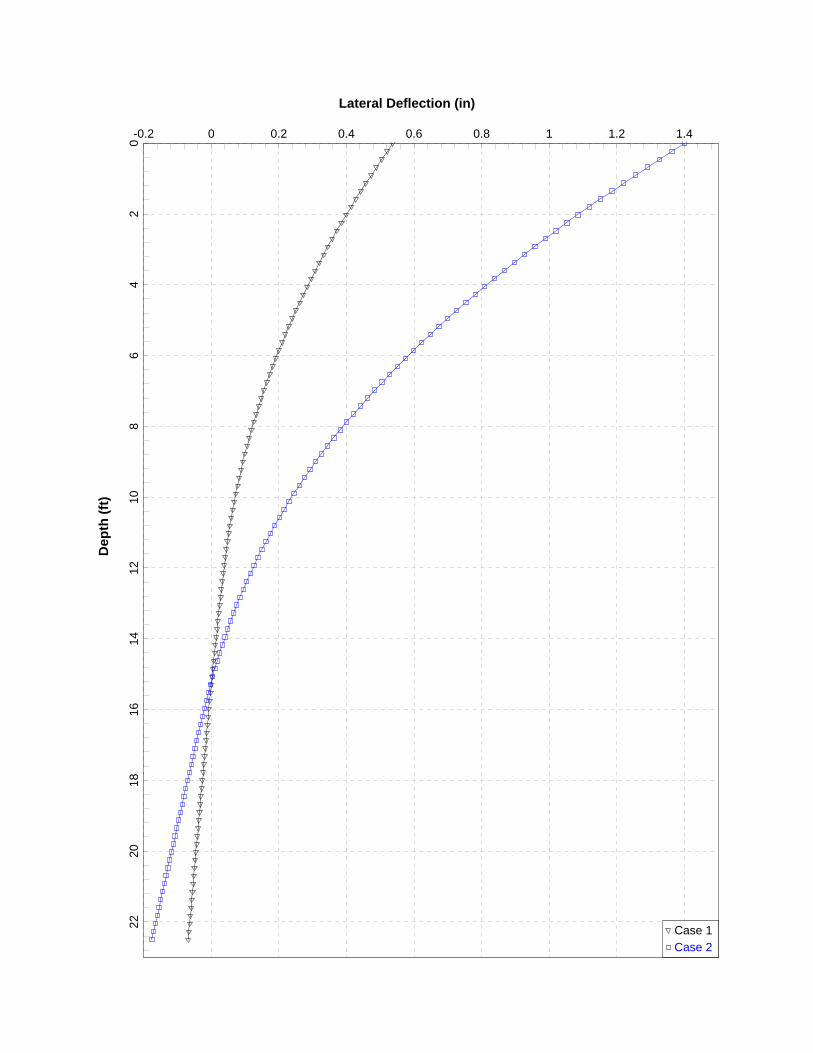
Lateral Deflection (in)D
epth
(ft)
-0.2 0 0.2 0.4 0.6 0.8 1 1.2 1.40
24
68
1012
1416
1820
22 Case 1Case 2
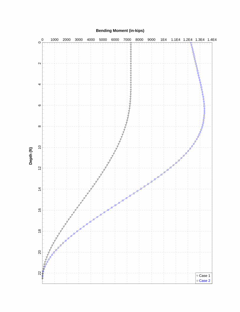
Bending Moment (in-kips)D
epth
(ft)
0 1000 2000 3000 4000 5000 6000 7000 8000 9000 1E4 1.1E4 1.2E4 1.3E4 1.4E40
24
68
1012
1416
1820
22 Case 1Case 2

Shear Force (kips)D
epth
(ft)
-120 -110 -100 -90 -80 -70 -60 -50 -40 -30 -20 -10 0 10 200
24
68
1012
1416
1820
22 Case 1Case 2