Embed Size (px)
Citation preview

G. Królczyk at al. Analiza trošenja reznog klina alata pri tokarenju duplex nehrđajućeg čelika
ISSN 1330-3651 (Print), ISSN 1848-6339 (Online) UDC/UDK 621.9.025.5.029:621.385.833
CUTTING WEDGE WEAR EXAMINATION DURING TURNING OF DUPLEX STAINLESS STEEL Grzegorz Królczyk, Stanisław Legutko, Pero Raos
Original scientific paper The purpose of the study was to determine the coated carbide tool surface topography. The study included determining detailed identification of wear mechanisms occurring on the rake face and major flank in the process of turning the DSS. The results of wear occurring on the tool both points were compared for the period of the steady-state wear of the tool point. Occurrence of various mechanisms, such as abrasive wear, was proven. Scanning Electron Microscopy SEM and Infinite Focus optical device for 3D surface measurement were used for the wear analysis. Keywords: Duplex Stainless Steel (DSS), machining, turning, surface layer, tool wear Analiza trošenja reznog klina alata pri tokarenju duplex nehrđajućeg čelika
Izvorni znanstveni članak Rad se bavi analizom topografskih karakteristika karbidne površine reznog alata. Istraživanjem je obuhvaćena detaljna analiza mehanizma trošenja rezne oštrice i prednje površine alata u procesu tokarenja duplex nehrđajućeg čelika. U stabilnom režimu uočeno je trošenje oba analizirana dijela reznog alata. Dokazana je pojava različitih mehanizama trošenja, primjerice abrazijskog trošenja. Trošenje površine analizirano je s pomoću elektronske pretražne mikroskopije (SEM) i optičkog uređaja Infinite Focus za trodimenzijsko mjerenje površina. Ključne riječi: Duplex nehrđajući čelik, obrada odvajanjem čestica, tokarenje, površinski sloj, trošenje alata 1 Introduction Duplex stainless steel is widely used for many industrial applications due to its unique properties. Good combination of its mechanical properties (high strength and toughness) and corrosion resistance makes it of great interest for a wide range of applications especially in the oil, chemical and power industry [1, 2]. However, machinability of the material is considered to be poor due to its inherent characteristics. The DSS machinability studies have not rendered a clear answer to the question how the cutting speed influences the condition of the cutting wedge [3, 9]. The wear of the cutting wedges is to be considered one of the most important problems of machining process investigation [4]. The contact phenomena on the tool flank surface are of interest because understanding them allows the explanation of tool flank wear and the formation of surface integrity of machined surfaces on workpieces. Nevertheless, there are few known studies available on the subject [5]. Machining costs are determined mostly by the time which is necessary for measuring and machining. Demands for higher productivity and a better use of cutting tools lead to a combination of machining parameters [6]. The investigation presented in the paper answers the question
what happens to the cutting wedge considering the form of its wear. 2 Research approach and experimental procedure 2.1 Workpiece and cutting wedge materials
Machined material was 1.4462 (DIN EN 10088-1) steel with a ferritic-austenitic structure containing about 50 % of austenite. The ultimate tensile strength Rm =700 MPa, Brinell hardness - 293 HB. The elemental composition of the machined material and technical details of the cutting tools are stated in Tab. 1 and Tab. 2 [9], respectively. Cutting tool inserts of TNMG 160408 designation clamped in the tool shank of ISO-MTGNL 2020-16 type were employed.
The examination of the wedges was performed after a time of cutting corresponding to 30 % of the tool life period. The measurements and analysis were performed on cutting wedges working without the use of a coolant-lubricant at cutting speeds of vc = 50 m/min and 150 m/min, f = 0,3 mm/rev, ap = 2 mm. The study was performed within a production facility. The investigation program was carried out on a CNC 400 Famot lathe – Pleszew.
Table 1 Chemical composition of 1.4462 duplex stainless steel
Element C max Si max Mn max P max S max Cr Ni Mo N Others
% wt. 0,03 1,00 2,00 0,030 0,020 21,0 23,0
4,50 6,50
2,50 3,50
0,10 0,22 -
Table 2 Cutting tool data
Tool Substrate Others
W1 MM 2025
Hardness: 1350 HV3 Grade: M25, P35
Coatings: Ti(C,N)-(2 µm) (Top layer) Al2O3-(1,5 µm) (Middle layer) TiN-(2 µm) (Bottom layer) Coating technique: CVD
Tehnički vjesnik 20, 3(2013), 413-418 413

Cutting wedge wear examination during turning of duplex stainless steel G. Królczyk et al.
2.2 Wear and wedge topography investigations
After cutting trials, the values VBB = 0,14 mm of flank wear were measured with the use of an Infinite Focus Measurement Machine (IFM) [7]. IFM is an optical 3D measurement device which allows the acquisition of datasets at a high depth of focus. The IFM 3.2 software version was used for the measurements. The surfaces of indexable tool inserts were verified using an ESEM TMP scanning electron microscope. 3 Results and discussions 3.1 Tool wear analysis The cutting wedge working at the cutting speed of vc = 150 m/min was subjected to measurements by means of an Infinite Focus device [7]. The examination consisted of the measurement of the wedge wear parameters on the rake face and determination of the cutting edge shape. In order to compare the cutting wedge wear, a new wedge was also measured to assemble the results and determine the dimensional differences. The compared results were to help us to determine the values of the wear parameters on the rake face of the cutting wedge and the character of the wedge wear depending on the cutting speed.
a) Rake face of the tool point W1 in real colour
(vc = 150 m/min, f = 0,3 mm/rev, ap = 2 mm, dry)
b) Rake face of the tool point W1 in pseudo colour (vc = 150 m/min, f = 0,3 mm/rev, ap = 2 mm, dry)
Figure 1 Topography of W1 tool wear during turning of DSS steel for vC = 150 m/min
The results of stereometry visualization of a cutting wedge working at cutting speed of 150 m/min are shown in Fig. 1. In the photographs, one can see a built-up edge on the rake face located next to the main cutting edge and between the main cutting edge and the chip breaker.
In order to determine the dimension differences between the individual wedges, two sets of 3D digital data of the cutting wedge geometrical structure were compared. The magnitudes characterizing the wedge geometry were measured and the surface structure photographed. The wedge surface structure photographs and its dimensions were subjected to analysis which could be divided into the following three steps: • alignment of two 3D-datasets • the depicted 3D-difference Dataset (Fig. 2) • visualized result data in a histogram.
Values calculated in this measurement were: • mean deviation • max deviation • min deviation.
Figure 2 Overlaid models of selection (region under investigation),
deviations displayed in pseudo colours As can be seen in Fig. 2 showing the differences
between unworn wedge working at the cutting speed of 150 m/min and that of an idle wedge, cutting edge lowering by 30 ÷ 50 µm, as well as the previously described built-up edge, are visible. The measurement results were as follows: • mean deviation −2,865 μm, • max. deviation 70,432 μm, • min. deviation −135,26 μm.
Those results allow for the statement that machining duplex steel at the speed of 150 m/min in the time of 30 % tool life causes significant lowering of the cutting edge, locally in excess of 70 µm, as well as a large built-up edge of maximum 135 µm. The mean deviation was 2,865 µm, which indicates significant wear of the cutting wedge and the prevalence of built-up edge over abrasion. Figure 3 shows a histogram of the distribution of vertices and upgrades located on the cutting wedge. It can be seen that the distribution is even. This proves that the 30 % tool life period is within the so called second stage of the cutting edge wear.
414 Technical Gazette 20, 3(2013), 413-418

G. Królczyk at al. Analiza trošenja reznog klina alata pri tokarenju duplex nehrđajućeg čelika
The measurement of the cutting edge rounding radius consisted in virtual cutting of the sample. The trajectory in the optical image was defined in order to obtain the desired 3D view of the profile. By means of basic geometrical tools, such as circles or angles, manual and
semi-automatic measurements were performed. The examinations included the following steps: • profile extraction with different width, • manual cursor measurement, • fitting of primitive geometrical forms.
Figure 3 Deviation values tool wear histogram during turning of DSS for vC = 150 m/min
Figure 4 Extracted profile of cutting wedge during turning of DSS for vC = 150 m/min
Fig. 4 shows an extracted cutting wedge profile
together with matched geometry. The cutting plate acc. to PN-ISO 1832:1998 [8] is designated E (E – rounded shape). Therefore it has the cutting edge radius rn.
In order to determine the influence of machining parameters on the form of the cutting wedge wear, tests with the cutting speed reduced to 50 m/min were performed. As in the case of the wedge working at 150 m/min, the surface topography was measured on the rake face, as well as the rounding radius of the cutting edge rn. Like in the case of the wedge working at the cutting speed of 150 m/min, a new wedge was measured for comparison, the geometrical structures of the two were compared to determine the differences.
The cutting wedge surface topography after turning duplex steel at the cutting speed of 50 m/min is shown in Fig. 5. The built-up edge on the rake face is located as in the case of the wedge working at the cutting speed of 150 m/min, next to the main cutting edge, but with significantly smaller dimensions. One can also see the place of chip friction between the main cutting edge and the chip breaker together with a small built-up edge.
In order to find the dimensional differences between a wedge working at the cutting speed of 50 m/min and an unworn one, two digital images of the wear form of the cutting edges were compared. The result of the comparison of the cutting wedges is the built-up edge, dimensions shown in Fig. 6. One can see less intensive
Flank wear Rake face
Tehnički vjesnik 20, 3(2013), 413-418 415

Cutting wedge wear examination during turning of duplex stainless steel G. Królczyk et al.
formation of built-up edge next to the main cutting edge than in the case of the wedge working at the cutting speed of 150 m/min. During the operation of the wedge at the reduced speed, lowering of the cutting edge did not occur, but an abrasion wear land was found on the rake face at the location of chip friction.
a) Rake face of the tool point W1 in real colour (vc = 50 m/min, f = 0,3 mm/rev, ap = 2 mm, dry)
b) Rake face of the tool point W1 in pseudo colour
(vc = 50 m/min, f = 0,3 mm/rev, ap = 2 mm, dry) Figure 5 Topography of W1 wedge wear during turning of DSS steel for
vc = 50 m/min
Figure 6 Overlaid models of selection (region under investigation), deviations displayed in pseudo colours
The measurement results were as follows:
• mean deviation −5,1034 μm • max. deviation 88,492 μm • min. deviation −117,71 μm.
Those results allow for the statement that the reduction of the cutting speed within the examined range of parameters of machining duplex steel results in a decrease of built-up edge on the rake face and eliminates lowering of the cutting edge. The mean deviation on the rake face of wedge no. 4 was −5,1034 µm while, at the same time, in the case of a wedge working at the cutting speed of 150 m/min, the value was −2,865 µm. Fig. 7 shows a histogram of the distribution of vertices and upgrades on the cutting wedge. In the figure one can see even distribution in the part from −20 to about 15 µm. Surface irregularities with the height of 40 ÷ 50 µm are about 2 % of the total number of irregularities. It can be seen that the cutting edge differs from the edge of the wedge working at the cutting speed of 150 m/min. Lowering of the cutting edge, on the other hand, has not been observed. Fig. 8 shows an extracted profile of a cutting wedge working at the speed of 50 m/min.
Figure 7 Deviation values tool wear histogram during turning of DSS for vc = 50 m/min
Based on the measurement of the geometry presented
in Fig. 8, it was determined that the radius of the cutting edge rounding rn was 42,418 µm. This confirms that machining of duplex stainless steel at higher speeds of the
416 Technical Gazette 20, 3(2013), 413-418
G. Królczyk at al. Analiza trošenja reznog klina alata pri tokarenju duplex nehrđajućeg čelika
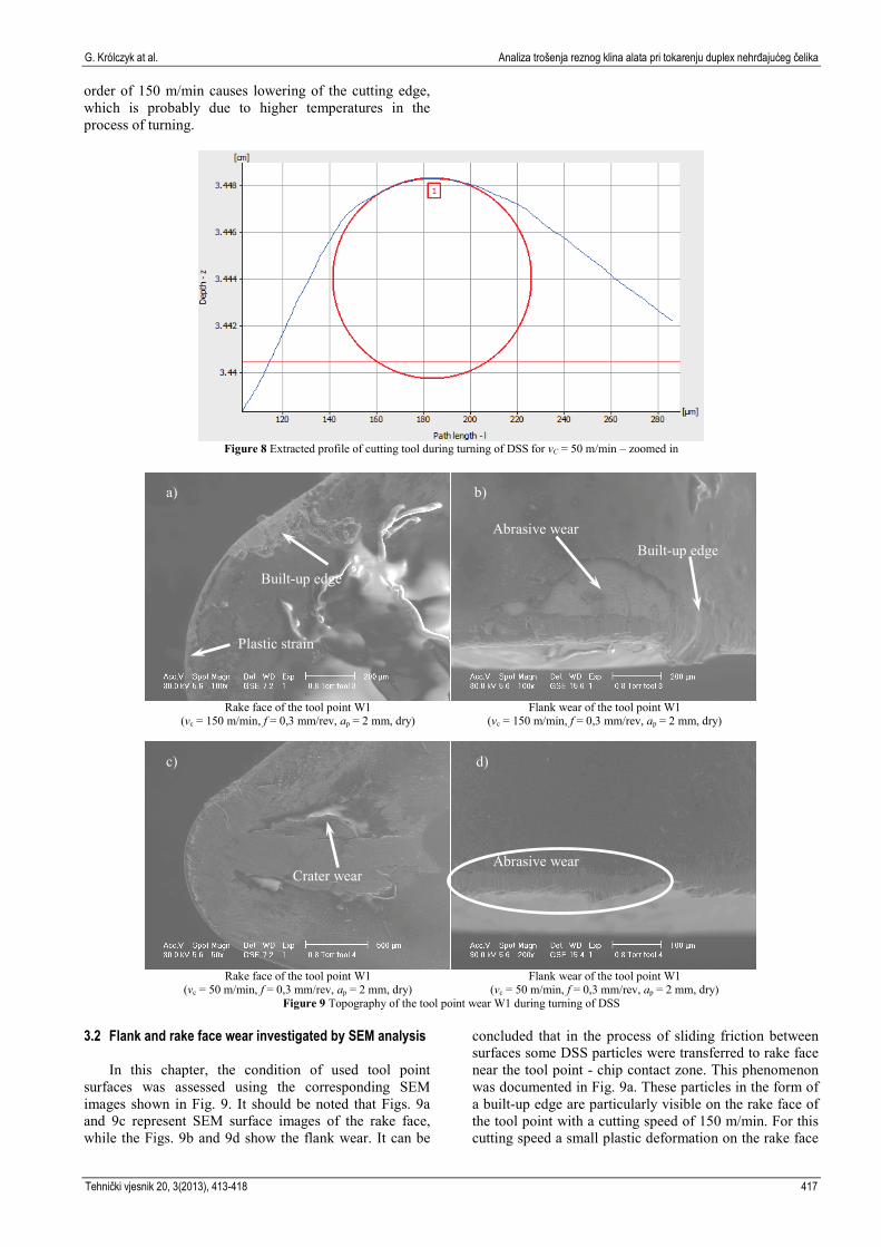
order of 150 m/min causes lowering of the cutting edge, which is probably due to higher temperatures in the process of turning.
Figure 8 Extracted profile of cutting tool during turning of DSS for vC = 50 m/min – zoomed in
Rake face of the tool point W1
(vc = 150 m/min, f = 0,3 mm/rev, ap = 2 mm, dry)
Flank wear of the tool point W1
(vc = 150 m/min, f = 0,3 mm/rev, ap = 2 mm, dry)
Rake face of the tool point W1
(vc = 50 m/min, f = 0,3 mm/rev, ap = 2 mm, dry)
Flank wear of the tool point W1
(vc = 50 m/min, f = 0,3 mm/rev, ap = 2 mm, dry) Figure 9 Topography of the tool point wear W1 during turning of DSS
3.2 Flank and rake face wear investigated by SEM analysis In this chapter, the condition of used tool point surfaces was assessed using the corresponding SEM images shown in Fig. 9. It should be noted that Figs. 9a and 9c represent SEM surface images of the rake face, while the Figs. 9b and 9d show the flank wear. It can be
concluded that in the process of sliding friction between surfaces some DSS particles were transferred to rake face near the tool point - chip contact zone. This phenomenon was documented in Fig. 9a. These particles in the form of a built-up edge are particularly visible on the rake face of the tool point with a cutting speed of 150 m/min. For this cutting speed a small plastic deformation on the rake face
Plastic strain
Built-up edge
Abrasive wear
Built-up edge
Crater wear
Abrasive wear
a) b)
c) d)
Tehnički vjesnik 20, 3(2013), 413-418 417

Cutting wedge wear examination during turning of duplex stainless steel G. Królczyk et al.
and the built-up edge with the clash of the major flank can be observed (Fig. 9b). Reducing the cutting speed to 50 m/min resulted in crater wear appearing on the rake face (Fig. 9c) and the abrasive wear of the major flank (Fig. 9d).
4 Conclusions
Based on the experimental testing of DSS machining using coated carbide tools, the following conclusions are drawn: 1) Increase of the cutting speed increases the intensity of
wear of the cutting edge.2) Flank wear was the predominant failure mode of
carbide coated tool performance and the major reasonof tool life reduction.
3) Adhesive interaction between machined and materialof wedge was observed at the rake face of the tool.
4) Wear deviations on the cutting tool coated with aceramic intermediate layer for parameters vc = 150m/min, f = 0,3 mm/rev, ap = 2 mm after a time ofcutting corresponding to 30 % of the tool life periodin dry turning were between –135 µm and 70 µm,however for cutting speed vc = 50 m/min the weardeviations range was smaller and their value wasbetween –5 µm and –117 µm.
5) The proposed method of measuring the topography ofthe tool point wear allows to accurately determine thewear on the rake face of the wedge.
5 References
[1] Cabrera, J. M.; Mateo, A.; Llanes, L.; Prado, J. M.; Anglada, M. Hot deformation of duplex stainless steels. // J. Mater. Process. Technol, 143–144(2003), pp. 321–325.
[2] Park, Y.H.; Lee, Z.H. // Mater. Sci. Eng. A297 (2001), pp. 78–84.
[3] Krolczyk, G.; Gajek, M.; Legutko, S. Predicting the tool life in the dry machining of duplex stainless steel. Eksploatacja i Niezawodnosc – Maintenance and Reliability, 15, 1(2013), pp. 62–65.
[4] Kupczyk, M. J. Manufacturing and exploitation of cutting tools with anti-wear coatings. Poznan University of Technology, Poznan, 2003 (in polish).
[5] Astakhov, V. P. // International Journal of Machine Tools and Manufacture, 44, 6 (2004), pp. 637–647.
[6] O’Sullivan, D.; Cotterell, M. // Journal of Materials Processing Technology, 124, 1–2 (2002), pp. 153–159.
[7] Alicona Imaging GMBH. InfiniteFocus® version 3.2. www.alicona.com
[8] PN-ISO 1832:1998. Indexable inserts for cutting tools. Designation.
[9] Krolczyk, G.; Legutko, S.; Gajek, M. Predicting the surface roughness in the dry machining of duplex stainless steel. // Metalurgija, 52, (2)(2013), pp. 259-262.
Symbols and abbreviations
ap – depth of cut in mm f – feed rate in mm/rev rn – rounding of the cutting edge in µm vc – cutting speed in m/min T – tool life in min VBB – width of flank wear in mm DSS – Duplex Stainless Steel.
Authors’ addresses
Grzegorz Królczyk, PhD. Eng. Faculty of Production Engineering and Logistics Opole University of Technology 76 Prószkowska Street, 45-758 Opole, Poland E-mail: [email protected]
Stanislaw Legutko, Prof. DSc. PhD. Eng., Prof. h. c. Faculty of Mechanical Engineering and Management Poznan University of Technology 3 Piotrowo Street, 60-965 Poznan, Poland E-mail: [email protected]
Pero Raos, Prof. dr. sc. J. J. Strossmayer University of Osijek Mechanical Engineering Faculty in Slavonski Brod Trg Ivane Brlić-Mažuranić 2 35000 Slavonski Brod, Croatia E-mail: [email protected]
418 Technical Gazette 20, 3(2013), 413-418